EP2013055B1 - Permanent magnet elevator disk brake - Google Patents
Permanent magnet elevator disk brake Download PDFInfo
- Publication number
- EP2013055B1 EP2013055B1 EP06750377.1A EP06750377A EP2013055B1 EP 2013055 B1 EP2013055 B1 EP 2013055B1 EP 06750377 A EP06750377 A EP 06750377A EP 2013055 B1 EP2013055 B1 EP 2013055B1
- Authority
- EP
- European Patent Office
- Prior art keywords
- permanent magnet
- housing
- magnetic field
- electromagnet
- braking member
- Prior art date
- Legal status (The legal status is an assumption and is not a legal conclusion. Google has not performed a legal analysis and makes no representation as to the accuracy of the status listed.)
- Not-in-force
Links
Images


Classifications
-
- B—PERFORMING OPERATIONS; TRANSPORTING
- B66—HOISTING; LIFTING; HAULING
- B66D—CAPSTANS; WINCHES; TACKLES, e.g. PULLEY BLOCKS; HOISTS
- B66D5/00—Braking or detent devices characterised by application to lifting or hoisting gear, e.g. for controlling the lowering of loads
- B66D5/02—Crane, lift hoist, or winch brakes operating on drums, barrels, or ropes
- B66D5/12—Crane, lift hoist, or winch brakes operating on drums, barrels, or ropes with axial effect
- B66D5/14—Crane, lift hoist, or winch brakes operating on drums, barrels, or ropes with axial effect embodying discs
-
- B—PERFORMING OPERATIONS; TRANSPORTING
- B66—HOISTING; LIFTING; HAULING
- B66D—CAPSTANS; WINCHES; TACKLES, e.g. PULLEY BLOCKS; HOISTS
- B66D5/00—Braking or detent devices characterised by application to lifting or hoisting gear, e.g. for controlling the lowering of loads
- B66D5/02—Crane, lift hoist, or winch brakes operating on drums, barrels, or ropes
- B66D5/24—Operating devices
- B66D5/30—Operating devices electrical
-
- F—MECHANICAL ENGINEERING; LIGHTING; HEATING; WEAPONS; BLASTING
- F16—ENGINEERING ELEMENTS AND UNITS; GENERAL MEASURES FOR PRODUCING AND MAINTAINING EFFECTIVE FUNCTIONING OF MACHINES OR INSTALLATIONS; THERMAL INSULATION IN GENERAL
- F16D—COUPLINGS FOR TRANSMITTING ROTATION; CLUTCHES; BRAKES
- F16D2121/00—Type of actuator operation force
- F16D2121/18—Electric or magnetic
- F16D2121/20—Electric or magnetic using electromagnets
- F16D2121/22—Electric or magnetic using electromagnets for releasing a normally applied brake
-
- F—MECHANICAL ENGINEERING; LIGHTING; HEATING; WEAPONS; BLASTING
- F16—ENGINEERING ELEMENTS AND UNITS; GENERAL MEASURES FOR PRODUCING AND MAINTAINING EFFECTIVE FUNCTIONING OF MACHINES OR INSTALLATIONS; THERMAL INSULATION IN GENERAL
- F16D—COUPLINGS FOR TRANSMITTING ROTATION; CLUTCHES; BRAKES
- F16D2129/00—Type of operation source for auxiliary mechanisms
- F16D2129/06—Electric or magnetic
- F16D2129/065—Permanent magnets
Definitions
- This invention generally relates to elevator systems. More particularly this invention relates to an elevator braking system.
- Elevator systems include a braking system to stop and hold an elevator car in a desired position.
- a braking system includes springs that force an axially moveable plate against a brake rotor having brake lining material. The resulting friction between the movable plate and the lining material stops and holds the elevator in place.
- Engagement of the moveable plate is known in the art as dropping the brake and is typically the default condition.
- the moveable plate is disengaged from the brake lining by a magnetic field generated by an electromagnet. The attractive force generated by the magnetic field overcomes the force of the springs and pulls the moveable plate away from the brake rotor. This is known in the art as lifting the brake.
- Electromagnets utilized for generating the magnetic field are inherently unstable in that attractive forces generated by the electromagnet increase as the moveable plate moves out of engagement toward a housing.
- the plate typically moves through an air gap of approximately 0.3 mm between an engaged and a disengaged position.
- the movement of the plate though this air gap and resulting contact with the brake rotor or a housing can result in objectionable noise that can be heard within the elevator car.
- Magnetic fields increase as the ferromagnetic parts come closer together, tending to create an acceleration of the movable plate on lifting that can produce objectionable noises.
- JP 2004 353684 describes an elevator system where an electromagnet is used to control the application of a brake by generating a magnetic flux equal and opposite to that of permanent magnets carrying out the braking.
- Additional devices that attempt to reduce noise generated by contact between the plate and the electromagnet housing include the use of elastomeric damping elements, such as O-rings.
- the 0-rings dampen movement to reduce the impact, and reduce noise.
- the O-rings are subject to creep, stress relaxation and aging. Over time these factors degrade the O-ring causing a noticeable increase in noise, along with a reduction in the force that engages the brake.
- the increase in noise and reduction in engagement force ultimately requires that the brake torque is re-adjusted, and O-rings be replaced in order to maintain the desired noise dampening characteristics.
- Other known devices include the use of an elastomeric bumper or pad. Such devices also suffer from the limited life span associated with the O-rings.
- this invention is a brake assembly for an elevator system that utilizes a permanent magnet and an electromagnet to stabilize application of a brake.
- an elevator brake assembly as claimed in claim 1 and a method of controlling an elevator braking system as claimed in claim 11.
- One example system designed according to this invention includes a permanent magnet that generates a first magnetic field in a direction that causes application of a clamping force on a brake disk.
- Springs disposed between a fixed electromagnet housing and the plate provide an additional biasing force and adjustment of applied forces on the plate.
- the attractive force of the permanent magnet and the biasing force of the coil springs clamp a brake disk between a fixed housing and an axially movable plate.
- the electromagnet includes a coil that is energized with current of a proper polarity to generate a second magnetic field opposite the first magnetic field.
- the rate and magnitude at which current is applied to the coil produces a controlled and variable second magnetic field.
- the second magnetic field produces a repulsive force against the first magnetic field to drive the permanent magnet housing away from the electromagnet housing. As the distance between the permanent magnet housing and the electromagnet housing increases, the difference in field strength between the two magnetic fields decreases until an equilibrium position is obtained.
- the brake can then be dropped in a controlled manner by ramping the electromagnetic current level down to regulate movement of the permanent magnet housing as it approaches the electromagnet housing.
- a controller reduces current to the coil such that the equilibrium position moves closer and closer to the fixed electromagnet housing and the dropped position.
- an example brake provides for controlled movement and application of the brake such that noise can be reduced without the use of damping bodies that wear and require replacement. Further, the example brake assembly provides a stable and durable brake assembly.
- FIG. 1 schematically shows an elevator system 10 including an elevator car 12 movable within a hoistway 14.
- a motor 16 moves the elevator car 12 in a known manner.
- a brake assembly 18 utilizes a permanent magnet in combination with an electromagnet to stabilize actuation.
- the brake assembly 18 is mounted adjacent the motor 16 for stopping and holding the elevator car 12 at a desired position within the hoistway 14.
- an example brake assembly 18 is schematically shown in an applied or dropped position.
- the motor 16 drives a shaft 28 about an axis 30.
- the shaft 28 extends from the motor 16 and into the brake assembly 18.
- the brake assembly 18 includes a fixed housing 20, an axially movable disk 22 and an axially movable plate 26.
- the disk 22 includes friction material 24 that engages both the housing 20 and the plate 26 when in the dropped position.
- the disk 22 is keyed to the shaft 28 in a known manner to allow axial movement but prevent rotational movement relative to the shaft 28.
- the keyed feature of the disk 22 is as known, and can be provided for example by a key within a keyway slot, or by mating splines on the disk 22 and shaft 28.
- the plate 26 is attached to a permanent magnet housing 34 by pins 46.
- the pins 46 extend through openings 48 within a fixed electromagnet housing 32.
- Permanent magnets 36 within the permanent magnet housing 34 generate a first magnetic field 52 providing an attractive force toward the electromagnet housing 32 in the direction indicated by the arrows.
- the permanent magnets 36 include a face 35 transverse to the direction of the first magnetic field 52.
- the face 35 includes north portions 61 and south portions 62.
- the permanent magnets 36 are configured to create the first magnetic field 52.
- the north and south portions 61, 62 are arranged about the shaft 28.
- the north and south portions 61, 62 are arranged annularly about the shaft 28 and are elliptically shaped.
- the elliptical shape maximizes the area of the north and south portions 61, 62 for the permanent magnet face 35.
- the north and south portions 61, 62 protrude from the face surface 35 a distance 39 to direct repulsive magnetic forces and prevent leakage that could degrade the strength of the magnetic field.
- the first magnetic field 52 provides an attractive force that drives the permanent magnet housing 34 toward the electromagnet housing 32 as shown by the arrows 52.
- the movement of the permanent magnet housing 34 is transferred to movement of the plate 26 through the pins 46.
- the disk 22 is in turn clamped between the housing 20 and the plate 26 to generate a braking force that prevents rotation of the shaft 28.
- the permanent magnets 36 continuously generate the first magnetic field 52 that produces an attractive force that drives the plate 26 toward the dropped or applied position as is shown by arrow 60.
- the strength of the magnetic field 52 is of a magnitude required to create a desired force to clamp the disk 22 and create the braking forces required for a specific application.
- the electromagnets 38 remain in an unpowered state with the brake assembly 18 in the dropped position.
- the electromagnet housing 32 is configured to cooperate with the permanent magnets 36 to provide the necessary mating configuration to produce the desired magnitude of the first magnetic field 52.
- the electromagnets 38 include a face 19 with a series of coils 40 wound around core members 41 and disposed annularly about the shaft 28.
- the cores 41 protrude outwardly form the face 19 a distance 45 ( Figure 2 ) to generate the desired repelling magnetic force.
- the majority of the magnetic field generated by the electromagnets 38 passes through the cores 41.
- the cores 41 are disposed in a parallel and aligned manner with the poles 61 and 62 of the face 35 of the permanent magnet 36.
- the electromagnet face 19 is configured to reduce the amount of magnetic flux that crosses the air gap therebetween. Such magnetic flux that crosses this air gap limits the ability to provide a repulsive force.
- the brake assembly 18 is shown in a released position or lifted position.
- the plate 26 is out of clamping contact with the disk 22 in the lifted position. Release of clamping contact provides for rotation of the disk 22 and thereby the shaft 28.
- the lifted position is provided by actuating the electromagnet 38 to generate a second magnetic field 54 opposing the first magnetic field 52 generated by the permanent magnets 36.
- Supplying current from a controller 50 ( Figure 6 ) to coils 40 of the electromagnets 38 generate the second magnetic field 54.
- the amount of current applied to the coils 40 governs the magnitude of strength of the second magnetic field 54.
- One example includes controlling the polarity of the current to direct the magnetic field as desired.
- the second magnetic field 54 is greater than the first magnetic field 52 generated by the permanent magnet 36.
- the combination of the first and second magnetic fields 52, 54 results in an overall repelling force that drives the permanent magnet housing 34 axial away from the electromagnet housing 32. Movement of the permanent magnet housing 34 produces corresponding axial movement of the pins 46 and the plate 26. The axial movement of the plate 26 releases the disk 22 such that no braking force is applied.
- the electromagnets 38 produce the second magnetic field 54 in strength proportional to an applied current from the controller 50. Accordingly, control of the amount and rate that current is applied provides control over movement of the permanent magnet housing 34. Current is controlled proportionally such that as a distance between the electromagnet housing 32 and the permanent magnet housing 34 changes, the forces can be accordingly adjusted to prevent uncontrolled impacts that can generate undesirable noise.
- coil springs 42 are provided between the plate 26 and the axially fixed electromagnet housing 32.
- the coil springs 42 bias the plate 26 toward the dropped position.
- coil springs 42 are illustrated other spring members, such as Belleville washers are within the contemplation of this invention.
- the coil springs 42 provide the bias force in the same direction as the permanent magnets 36.
- the coil springs 42 also provide an adjustment function for balancing the forces produced by the permanent magnets 36 against the forces produced by the electromagnets 38.
- the example coil springs 42 are partially disposed within spring pockets 43 within the plate 26.
- Adjusters 44 provided for each coil spring 42 can adjust the biasing force produced by the springs 42.
- the adjusters 44 are a known configuration such as for example a threaded plug for changing a depth of the spring pocket 43 and thereby the corresponding spring force.
- the illustrated example includes four coil springs 42, however, any number of coil springs 42 can be utilized for balancing forces and movement of the plate 26 as are desired for application specific requirements.
- the coil springs 42 are disposed within the spring pockets 43 within the plate 26. However, the springs 42 may also be mounted within the electromagnet housing 32.
- the adjusters 44 are a known configuration such as for example, a threaded plug for changing a depth of the spring pocket 43 and thereby the spring force. In this example, the strength of the magnetic field 54 is sufficient to overcome the bias of the springs 42 and the magnetic field 52 for lifting the brake.
- the permanent magnets 36 remain in a desired position relative to the fixed electromagnet housing 32.
- the equilibrium position can be adjusted by modifying the current level in the coils 40.
- the brake can then be dropped in a controlled manner by ramping the current level down to regulate movement of the permanent magnet housing 34 as it approaches the electromagnet housing 32.
- the controller 50 reduces current to the coils 40 from the equilibrium position to move the permanent magnets 36 closer and closer to the fixed electromagnet housing 32 and the dropped position.
- the example brake assembly provides for controlled movement and application of the brake to minimize noise without using damping bodies that wear and require replacement. Further, the example brake assembly provides a stable and durable brake assembly.
Description
- This invention generally relates to elevator systems. More particularly this invention relates to an elevator braking system.
- Elevator systems include a braking system to stop and hold an elevator car in a desired position. Typically, a braking system includes springs that force an axially moveable plate against a brake rotor having brake lining material. The resulting friction between the movable plate and the lining material stops and holds the elevator in place. Engagement of the moveable plate is known in the art as dropping the brake and is typically the default condition. The moveable plate is disengaged from the brake lining by a magnetic field generated by an electromagnet. The attractive force generated by the magnetic field overcomes the force of the springs and pulls the moveable plate away from the brake rotor. This is known in the art as lifting the brake.
- Electromagnets utilized for generating the magnetic field are inherently unstable in that attractive forces generated by the electromagnet increase as the moveable plate moves out of engagement toward a housing. The plate typically moves through an air gap of approximately 0.3 mm between an engaged and a disengaged position. The movement of the plate though this air gap and resulting contact with the brake rotor or a housing can result in objectionable noise that can be heard within the elevator car. Magnetic fields increase as the ferromagnetic parts come closer together, tending to create an acceleration of the movable plate on lifting that can produce objectionable noises.
JP 2004 353684 - If the magnetic field decays too quickly when dropping the brake, then the movable plate is accelerated by the springs against the brake rotor and brake housing also generating noise. The brake noise is reduced somewhat by using a diode circuit to delay the collapse of the magnetic field when dropping the brake. However, such a device can cause undesirable delays in engaging the brake, while not sufficiently reducing the noise.
- Additional devices that attempt to reduce noise generated by contact between the plate and the electromagnet housing include the use of elastomeric damping elements, such as O-rings. The 0-rings dampen movement to reduce the impact, and reduce noise. Disadvantageously, the O-rings are subject to creep, stress relaxation and aging. Over time these factors degrade the O-ring causing a noticeable increase in noise, along with a reduction in the force that engages the brake. The increase in noise and reduction in engagement force ultimately requires that the brake torque is re-adjusted, and O-rings be replaced in order to maintain the desired noise dampening characteristics. Other known devices include the use of an elastomeric bumper or pad. Such devices also suffer from the limited life span associated with the O-rings.
- Accordingly, there is a need for an improved brake system that provides the desired holding and stopping force in a stable controlled manner to prevent undesirable impacts and reduce objectionable noise, improve durability and extend operational life.
- In general terms, this invention is a brake assembly for an elevator system that utilizes a permanent magnet and an electromagnet to stabilize application of a brake.
- According to the present invention, there is provided an elevator brake assembly as claimed in claim 1 and a method of controlling an elevator braking system as claimed in claim 11.
- One example system designed according to this invention includes a permanent magnet that generates a first magnetic field in a direction that causes application of a clamping force on a brake disk. Springs disposed between a fixed electromagnet housing and the plate provide an additional biasing force and adjustment of applied forces on the plate. In one example brake assembly, when the brake is in a dropped or applied position, the attractive force of the permanent magnet and the biasing force of the coil springs clamp a brake disk between a fixed housing and an axially movable plate.
- The electromagnet includes a coil that is energized with current of a proper polarity to generate a second magnetic field opposite the first magnetic field. The rate and magnitude at which current is applied to the coil produces a controlled and variable second magnetic field. The second magnetic field produces a repulsive force against the first magnetic field to drive the permanent magnet housing away from the electromagnet housing. As the distance between the permanent magnet housing and
the electromagnet housing increases, the difference in field strength between the two magnetic fields decreases until an equilibrium position is obtained. - The brake can then be dropped in a controlled manner by ramping the electromagnetic current level down to regulate movement of the permanent magnet housing as it approaches the electromagnet housing. A controller reduces current to the coil such that the equilibrium position moves closer and closer to the fixed electromagnet housing and the dropped position.
- Accordingly, an example brake provides for controlled movement and application of the brake such that noise can be reduced without the use of damping bodies that wear and require replacement. Further, the example brake assembly provides a stable and durable brake assembly.
- The various features and advantages of this invention will become apparent to those skilled in the art from the following detailed description of the currently preferred embodiments. The drawings that accompany the detailed description can be briefly described as follows.
-
-
Figure 1 schematically illustrates an example elevator system according to this invention. -
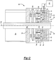
Figure 2 is a schematic representation of an example elevator brake system designed according to this invention. -
Figure 3 is a schematic view of a face of an example permanent magnet according to this invention. -
Figure 4 is a schematic view of an interface between a permanent magnet and an electromagnet in a dropped position. -
Figure 5 is a schematic view of a face of an example electromagnet according to this invention. -
Figure 6 is a schematic view of the example elevator brake system in a lifted position -
Figure 7 is a schematic view of the interface between the permanent magnet and the electromagnet in a lifted position. -
Figure 1 schematically shows anelevator system 10 including anelevator car 12 movable within ahoistway 14. Amotor 16 moves theelevator car 12 in a known manner. Abrake assembly 18 utilizes a permanent magnet in combination with an electromagnet to stabilize actuation. Thebrake assembly 18 is mounted adjacent themotor 16 for stopping and holding theelevator car 12 at a desired position within thehoistway 14. - Referring to
Figure 2 , anexample brake assembly 18 is schematically shown in an applied or dropped position. Themotor 16 drives ashaft 28 about anaxis 30. Theshaft 28 extends from themotor 16 and into thebrake assembly 18. Thebrake assembly 18 includes afixed housing 20, an axiallymovable disk 22 and an axiallymovable plate 26. Thedisk 22 includesfriction material 24 that engages both thehousing 20 and theplate 26 when in the dropped position. Further, thedisk 22 is keyed to theshaft 28 in a known manner to allow axial movement but prevent rotational movement relative to theshaft 28. The keyed feature of thedisk 22 is as known, and can be provided for example by a key within a keyway slot, or by mating splines on thedisk 22 andshaft 28. - The
plate 26 is attached to apermanent magnet housing 34 bypins 46. Thepins 46 extend throughopenings 48 within a fixedelectromagnet housing 32.Permanent magnets 36 within thepermanent magnet housing 34 generate a firstmagnetic field 52 providing an attractive force toward theelectromagnet housing 32 in the direction indicated by the arrows. Thepermanent magnets 36 include aface 35 transverse to the direction of the firstmagnetic field 52. - Referring to
Figure 3 , with continuing reference toFigure 2 , theface 35 includesnorth portions 61 andsouth portions 62. Thepermanent magnets 36 are configured to create the firstmagnetic field 52. The north andsouth portions shaft 28. The north andsouth portions shaft 28 and are elliptically shaped. The elliptical shape maximizes the area of the north andsouth portions permanent magnet face 35. The north andsouth portions distance 39 to direct repulsive magnetic forces and prevent leakage that could degrade the strength of the magnetic field. - The first
magnetic field 52 provides an attractive force that drives thepermanent magnet housing 34 toward theelectromagnet housing 32 as shown by thearrows 52. The movement of thepermanent magnet housing 34 is transferred to movement of theplate 26 through thepins 46. Thedisk 22 is in turn clamped between thehousing 20 and theplate 26 to generate a braking force that prevents rotation of theshaft 28. - Referring to
Figure 4 , thepermanent magnets 36 continuously generate the firstmagnetic field 52 that produces an attractive force that drives theplate 26 toward the dropped or applied position as is shown byarrow 60. The strength of themagnetic field 52 is of a magnitude required to create a desired force to clamp thedisk 22 and create the braking forces required for a specific application. - The
electromagnets 38 remain in an unpowered state with thebrake assembly 18 in the dropped position. Theelectromagnet housing 32 is configured to cooperate with thepermanent magnets 36 to provide the necessary mating configuration to produce the desired magnitude of the firstmagnetic field 52. - Referring to
Figure 5 , theelectromagnets 38 include aface 19 with a series ofcoils 40 wound aroundcore members 41 and disposed annularly about theshaft 28. Thecores 41 protrude outwardly form the face 19 a distance 45 (Figure 2 ) to generate the desired repelling magnetic force. The majority of the magnetic field generated by theelectromagnets 38 passes through thecores 41. Thecores 41 are disposed in a parallel and aligned manner with thepoles face 35 of thepermanent magnet 36. Theelectromagnet face 19 is configured to reduce the amount of magnetic flux that crosses the air gap therebetween. Such magnetic flux that crosses this air gap limits the ability to provide a repulsive force. - Although a specific configuration is illustrated, a worker with the benefit of this disclosure would understand that other configuration would fall within the contemplation of this invention to include features to optimize the attractive forces generated by the
permanent magnets 36. For example, such features could include a desired air gap, and mating components that improve and optimize the magnetic flux path for application specific requirements. - Referring to
Figures 6 and7 , thebrake assembly 18 is shown in a released position or lifted position. Theplate 26 is out of clamping contact with thedisk 22 in the lifted position. Release of clamping contact provides for rotation of thedisk 22 and thereby theshaft 28. The lifted position is provided by actuating theelectromagnet 38 to generate a secondmagnetic field 54 opposing the firstmagnetic field 52 generated by thepermanent magnets 36. Supplying current from a controller 50 (Figure 6 ) tocoils 40 of theelectromagnets 38 generate the secondmagnetic field 54. In one example, the amount of current applied to thecoils 40 governs the magnitude of strength of the secondmagnetic field 54. One example includes controlling the polarity of the current to direct the magnetic field as desired. - The second
magnetic field 54 is greater than the firstmagnetic field 52 generated by thepermanent magnet 36. The combination of the first and secondmagnetic fields permanent magnet housing 34 axial away from theelectromagnet housing 32. Movement of thepermanent magnet housing 34 produces corresponding axial movement of thepins 46 and theplate 26. The axial movement of theplate 26 releases thedisk 22 such that no braking force is applied. - The
electromagnets 38 produce the secondmagnetic field 54 in strength proportional to an applied current from thecontroller 50. Accordingly, control of the amount and rate that current is applied provides control over movement of thepermanent magnet housing 34. Current is controlled proportionally such that as a distance between theelectromagnet housing 32 and thepermanent magnet housing 34 changes, the forces can be accordingly adjusted to prevent uncontrolled impacts that can generate undesirable noise. - In the illustrated example, coil springs 42 are provided between the
plate 26 and the axially fixedelectromagnet housing 32. The coil springs 42 bias theplate 26 toward the dropped position. Although coil springs 42 are illustrated other spring members, such as Belleville washers are within the contemplation of this invention. - The coil springs 42 provide the bias force in the same direction as the
permanent magnets 36. The coil springs 42 also provide an adjustment function for balancing the forces produced by thepermanent magnets 36 against the forces produced by theelectromagnets 38. The example coil springs 42 are partially disposed within spring pockets 43 within theplate 26.Adjusters 44 provided for eachcoil spring 42 can adjust the biasing force produced by thesprings 42. Theadjusters 44 are a known configuration such as for example a threaded plug for changing a depth of the spring pocket 43 and thereby the corresponding spring force. The illustrated example includes fourcoil springs 42, however, any number ofcoil springs 42 can be utilized for balancing forces and movement of theplate 26 as are desired for application specific requirements. - The coil springs 42 are disposed within the spring pockets 43 within the
plate 26. However, thesprings 42 may also be mounted within theelectromagnet housing 32. Theadjusters 44 are a known configuration such as for example, a threaded plug for changing a depth of the spring pocket 43 and thereby the spring force. In this example, the strength of themagnetic field 54 is sufficient to overcome the bias of thesprings 42 and themagnetic field 52 for lifting the brake. - As the distance between the
permanent magnet housing 34 and theelectromagnet housing 32 increases, the difference in force between the two magnetic fields decreases until an equilibrium position is obtained. In the equilibrium position, thepermanent magnets 36 remain in a desired position relative to the fixedelectromagnet housing 32. The equilibrium position can be adjusted by modifying the current level in thecoils 40. - The brake can then be dropped in a controlled manner by ramping the current level down to regulate movement of the
permanent magnet housing 34 as it approaches theelectromagnet housing 32. Thecontroller 50 reduces current to thecoils 40 from the equilibrium position to move thepermanent magnets 36 closer and closer to the fixedelectromagnet housing 32 and the dropped position. - Accordingly, the example brake assembly provides for controlled movement and application of the brake to minimize noise without using damping bodies that wear and require replacement. Further, the example brake assembly provides a stable and durable brake assembly.
- The preceding description is exemplary rather than limiting in nature. Variations and modifications to the disclosed examples may become apparent to those skilled in the art that do not necessarily depart from the invention. The scope of legal protection given to this invention can only be determined by studying the following claims.
Claims (12)
- An elevator brake assembly (18) comprising:a braking member (26) movable between an engaged position and a disengaged position;a permanent magnet (36) generating a first magnetic field (52) for biasing said braking member (26) toward said engaged position; andan electromagnet (38) actuatable for generating a second magnetic field (54) opposing said first magnetic field (52) for causing movement of said braking member (26) from said engaged position toward said disengaged position;characterised in that said electromagnet (38) is disposed within a housing (32) and said permanent magnet (36) is movable relative to said housing (32), wherein said electromagnet (38) comprises a coil (40) disposed within said housing (32), and including a controller (50) that controls a current supplied to said coil (40) for generating said second magnetic field (54) in a selectively controlled manner, wherein said controller (50) varies the current in response to a position of said permanent magnet (36) relative to said housing (32).
- The assembly as recited in claim 1, wherein said braking member (26) cooperates with a fixed housing (20) to apply a braking force, said electromagnet (38) is fixed relative to movement of said housing (20) and said permanent magnet (36) such that said braking member (26) and said permanent magnet (36) move in unison.
- The assembly as recited in claim 1 or 2, wherein said housing (32) includes at least one opening (48), and said permanent magnet (36) and said braking member (26) are coupled together by at least one pin (46) extending at least partially through said at least one opening (48) in said housing (32).
- The assembly as recited in claim 1, 2, or 3, including springs (42) for adjusting movement of said braking member (26) relative to said housing (32).
- The assembly as recited in claim 4, including an adjustment device (44) for adjusting a force exerted by said springs (42) between said housing (32) and said plate (26) to balance a braking force generated by a combination of said springs (42) and said first magnetic field (52).
- The assembly as recited in any preceding claim, wherein said electromagnet (38) includes a plurality of coil assemblies (40) wound about a corresponding plurality of core members (41) that protrude from a face (19) of said permanent magnet (36).
- The assembly as recited in any preceding claim, wherein said permanent magnet (36) includes a plurality of north core portions (61) and a corresponding plurality of south core portions (62) protruding from a face surface (37).
- An elevator system (10) comprising:an elevator car (12);a motor assembly (16) for moving said elevator car (12); anda braking system (18) comprising a rotor (22) driven by said motor assembly (16) and a brake assembly (18) as recited in any preceding claim, wherein said braking member (26) is selectively movable for engaging said rotor (22), said permanent magnet (36) generates a first magnetic field (52) biasing said braking member (26) toward engagement with said rotor (22), and said electromagnet (38) generates a repulsing magnetic field (54) opposing said first magnetic field (52) for moving said permanent magnet (36) thereby controlling movement of said braking member (26).
- The system as recited in claim 8, wherein said electromagnet (38) generates said repulsive magnetic field (54) in a selective manner for controlling a relative position between said braking member (26) and said rotor (22).
- The system as recited in claim 9, wherein said electromagnet (38) is disposed within a housing (32) fixed relative to movement of said braking member (26) and said permanent magnet (36), said braking member (26) and said permanent magnet (36) are coupled by at least one pin (46) extending at least partially through openings (48) within said housing (32), and wherein said permanent magnet (36) is disposed on an opposite side of said housing (32) from said braking member (26).
- A method of controlling an elevator braking system, said method comprising the steps of:a) generating a first magnetic field (52) with a permanent magnet (36) for applying a braking force; andb) generating a second magnetic field (54) opposing said first magnetic field (52) with an electromagnet (38) for releasing the braking force;characterised in that said electromagnet (38) is disposed within a housing (32) and said permanent magnet (36) is movable relative to said housing (32) and in that the method further comprises:selectively controlling current applied to said electromagnet (38) for controlling a strength of said second magnetic field (54); andvarying the current applied to said electromagnet (38) in response to a position of said permanent magnet (36) relative to said housing (32).
- The method as recited in claim 11 including controlling a relative position between moveable members of the braking system by selectively controlling a difference between said first magnetic field (52) and said second magnetic field (54).
Applications Claiming Priority (1)
| Application Number | Priority Date | Filing Date | Title |
|---|---|---|---|
| PCT/US2006/014326 WO2007120132A1 (en) | 2006-04-17 | 2006-04-17 | Permanent magnet elevator disk brake |
Publications (3)
| Publication Number | Publication Date |
|---|---|
| EP2013055A1 EP2013055A1 (en) | 2009-01-14 |
| EP2013055A4 EP2013055A4 (en) | 2013-04-03 |
| EP2013055B1 true EP2013055B1 (en) | 2018-07-04 |
Family
ID=38609795
Family Applications (1)
| Application Number | Title | Priority Date | Filing Date |
|---|---|---|---|
| EP06750377.1A Not-in-force EP2013055B1 (en) | 2006-04-17 | 2006-04-17 | Permanent magnet elevator disk brake |
Country Status (7)
| Country | Link |
|---|---|
| US (1) | US8151950B2 (en) |
| EP (1) | EP2013055B1 (en) |
| JP (1) | JP5070280B2 (en) |
| CN (1) | CN101583511B (en) |
| ES (1) | ES2677560T3 (en) |
| HK (1) | HK1138242A1 (en) |
| WO (1) | WO2007120132A1 (en) |
Families Citing this family (25)
| Publication number | Priority date | Publication date | Assignee | Title |
|---|---|---|---|---|
| EP2234913B1 (en) * | 2007-12-10 | 2015-09-02 | Otis Elevator Company | Elevator brake device including permanent magnet bias to apply a braking force |
| US8256579B2 (en) * | 2009-12-23 | 2012-09-04 | Yanhua Jia | Elevator car brake |
| US9365392B2 (en) | 2011-01-19 | 2016-06-14 | Smart Lifts, Llc | System having multiple cabs in an elevator shaft and control method thereof |
| US8430210B2 (en) | 2011-01-19 | 2013-04-30 | Smart Lifts, Llc | System having multiple cabs in an elevator shaft |
| US8925689B2 (en) | 2011-01-19 | 2015-01-06 | Smart Lifts, Llc | System having a plurality of elevator cabs and counterweights that move independently in different sections of a hoistway |
| FI20115547A0 (en) | 2011-06-07 | 2011-06-07 | Kone Corp | Method and arrangement for adjusting the brake |
| GB2506062B (en) | 2011-06-16 | 2017-12-20 | Otis Elevator Co | Permanent magnet centering system for brake |
| KR101408092B1 (en) * | 2013-02-19 | 2014-06-19 | 주식회사 고영테크놀러지 | Magnetic brake |
| FR3007400A1 (en) * | 2013-06-24 | 2014-12-26 | Familor | BLOCKING AUTO LIFTING SYSTEM |
| US20170001616A1 (en) * | 2013-12-16 | 2017-01-05 | Miktech Co., Ltd. | Permanent magnet type electromagnetic braking cylinder |
| KR101511642B1 (en) | 2014-01-17 | 2015-04-13 | 한양대학교 에리카산학협력단 | Magnetic break |
| DE102014220414A1 (en) * | 2014-10-08 | 2016-04-14 | Brose Fahrzeugteile Gmbh & Co. Kg, Hallstadt | Permanent magnet brake for a drive device for adjusting a vehicle part |
| CN107001016A (en) * | 2014-12-10 | 2017-08-01 | 奥的斯电梯公司 | The brake assemblies of elevator device |
| US9903429B2 (en) * | 2015-02-12 | 2018-02-27 | Warner Electric Technology Llc | Brake with a reed switch for indicating an operating condition of the brake |
| CN107304022B (en) | 2016-04-21 | 2021-07-06 | 奥的斯电梯公司 | Escalator brake system and escalator brake control method |
| US10214382B2 (en) | 2017-01-11 | 2019-02-26 | Otis Elevator Company | Disk damping device |
| CN106763344B (en) * | 2017-03-28 | 2019-01-25 | 哈尔滨工业大学 | A kind of low power consumption permanent magnet brake based on force compensating in spring |
| US10612610B2 (en) * | 2018-04-12 | 2020-04-07 | Warner Electric Technology Llc | Bistable Brake |
| EP3608273B1 (en) | 2018-08-10 | 2022-09-28 | Otis Elevator Company | Elevator safety gear actuation device |
| CN110835065B (en) * | 2018-08-17 | 2022-02-01 | 奥的斯电梯公司 | Elevator braking device and elevator system |
| CN111156269B (en) * | 2018-11-08 | 2022-07-26 | 鲁班嫡系机器人(深圳)有限公司 | Brake equipment, motion subassembly and automation equipment |
| JP7217815B2 (en) * | 2019-11-13 | 2023-02-03 | 三菱電機株式会社 | electromagnetic brake |
| CN115594108A (en) * | 2021-07-09 | 2023-01-13 | 奥的斯电梯公司(Us) | Static plate assembly of brake, brake and elevator system |
| CN114455420A (en) * | 2021-12-30 | 2022-05-10 | 上海新时达电气股份有限公司 | Control method and device of electromagnetic brake, electronic equipment and storage medium |
| CN116915017B (en) * | 2023-09-11 | 2023-12-12 | 江苏恒立液压股份有限公司 | Linear actuating device, lifting equipment and control method |
Family Cites Families (22)
| Publication number | Priority date | Publication date | Assignee | Title |
|---|---|---|---|---|
| US2886149A (en) * | 1955-07-18 | 1959-05-12 | Baermann Max | Magnetic friction brake or clutch |
| US3512618A (en) * | 1968-08-22 | 1970-05-19 | Wolfgang Schafer | Electric brake with permanent magnet |
| US3642104A (en) * | 1968-08-22 | 1972-02-15 | Wolfgang Schafer | Electric couplings with permanent magnet |
| US3730317A (en) * | 1971-07-21 | 1973-05-01 | Eaton Corp | Electromagnetic coupling with permanent magnets |
| US3741353A (en) * | 1971-10-04 | 1973-06-26 | Us Navy | Bi-stable brake |
| US3866729A (en) * | 1973-06-13 | 1975-02-18 | Automatic Research Dev Co | Electromagnetic operated clutches and brakes |
| AU534147B2 (en) | 1979-01-30 | 1984-01-05 | General Electric Company | Polyester-polyarylene ester compositions |
| JPS5913385Y2 (en) * | 1979-02-08 | 1984-04-20 | 神鋼電機株式会社 | Permanent magnet actuated electromagnetic brake |
| US4811820A (en) * | 1986-01-12 | 1989-03-14 | Kone Oy | Disk brake motor |
| US5121018A (en) * | 1991-03-04 | 1992-06-09 | Lucas Aerospace Power Equipment Corporation | Latching brake using permanent magnet |
| US5202539A (en) * | 1991-08-28 | 1993-04-13 | Inventio Ag | Emergency brake apparatus for an elevator |
| SE500708C2 (en) * | 1992-12-18 | 1994-08-15 | Eg Technology Ab | Elevator machinery with friction brake |
| JPH0742775A (en) * | 1993-07-29 | 1995-02-10 | Toshiba Corp | Disk brake adjusting jig |
| JP3082565B2 (en) * | 1994-03-16 | 2000-08-28 | 神鋼電機株式会社 | Non-excitation actuated electromagnetic brake / clutch |
| JP3303656B2 (en) * | 1996-02-28 | 2002-07-22 | 神鋼電機株式会社 | Rubber damper type permanent magnet type electromagnetic brake |
| US5717174A (en) | 1996-05-08 | 1998-02-10 | Inventio Ag | Elevator brake drop silencing apparatus and method |
| JPH10184739A (en) * | 1996-12-27 | 1998-07-14 | Shinko Electric Co Ltd | Manual releasing device for unexcited operation type electromagnetic brake/clutch |
| DE19752543A1 (en) * | 1997-11-27 | 1999-06-02 | Bosch Gmbh Robert | Magnetic brake and electromechanical braking device with a magnetic brake |
| JPH11215767A (en) * | 1998-01-20 | 1999-08-06 | Victor Co Of Japan Ltd | Rotary body supporting equipment |
| JP2004353684A (en) | 2003-05-27 | 2004-12-16 | Hitachi Ltd | Braking device |
| DE102004003677A1 (en) * | 2004-01-24 | 2005-08-11 | Kendrion Binder Magnete Gmbh | Spring pressure brake to open electromagnetically for an drive mechanism rotates with a shaft, an electromagnet and a permanent magnet |
| DE102005063242B4 (en) * | 2005-12-20 | 2011-01-13 | Carl Zeiss Industrielle Messtechnik Gmbh | Magnetic coupling, in particular for locking a rotary joint in a coordinate measuring machine |
-
2006
- 2006-04-17 CN CN2006800542390A patent/CN101583511B/en not_active Expired - Fee Related
- 2006-04-17 ES ES06750377.1T patent/ES2677560T3/en active Active
- 2006-04-17 WO PCT/US2006/014326 patent/WO2007120132A1/en active Application Filing
- 2006-04-17 JP JP2009506464A patent/JP5070280B2/en not_active Expired - Fee Related
- 2006-04-17 EP EP06750377.1A patent/EP2013055B1/en not_active Not-in-force
- 2006-04-17 US US12/296,152 patent/US8151950B2/en active Active
-
2010
- 2010-05-05 HK HK10104412.0A patent/HK1138242A1/en not_active IP Right Cessation
Non-Patent Citations (1)
| Title |
|---|
| None * |
Also Published As
| Publication number | Publication date |
|---|---|
| US20090194370A1 (en) | 2009-08-06 |
| HK1138242A1 (en) | 2010-08-20 |
| CN101583511A (en) | 2009-11-18 |
| JP2009533301A (en) | 2009-09-17 |
| CN101583511B (en) | 2013-01-16 |
| EP2013055A1 (en) | 2009-01-14 |
| JP5070280B2 (en) | 2012-11-07 |
| WO2007120132A1 (en) | 2007-10-25 |
| ES2677560T3 (en) | 2018-08-03 |
| US8151950B2 (en) | 2012-04-10 |
| EP2013055A4 (en) | 2013-04-03 |
Similar Documents
| Publication | Publication Date | Title |
|---|---|---|
| EP2013055B1 (en) | Permanent magnet elevator disk brake | |
| EP2234913B1 (en) | Elevator brake device including permanent magnet bias to apply a braking force | |
| US7699145B2 (en) | Elevator disk brake with damping | |
| EP2197774B1 (en) | Elevator brake with magneto-rheological fluid | |
| EP1423626A1 (en) | Electromagnetic brake with variable spring rate damping members | |
| US5739610A (en) | Electro-magnetic device | |
| KR20210089642A (en) | Electromechanical on-off brake with integral damper structure | |
| KR20040066129A (en) | Hoist for elevator | |
| EP3628636B1 (en) | Elevator braking device and elevator system | |
| EP2607291B1 (en) | Electromagnetic actuator, brake arrangement comprising the electromagnetic actuator, and a method for reducing the energy consumption of the electromagnetic actuator | |
| EP1897835A1 (en) | Brake device for elevator | |
| EP3712025B1 (en) | Silent electromagnetic brake | |
| EP3822208A1 (en) | Electromagnetic brake configured to slow deceleration rate of an elevator during braking | |
| WO2006082646A1 (en) | Hoist of elevator | |
| JP6606456B2 (en) | Electromagnetic brake device | |
| JP2012229002A (en) | Brake system and friction pair and brake pad for brake system | |
| KR20000022507A (en) | Electromagnetically releasable friction safety brake |
Legal Events
| Date | Code | Title | Description |
|---|---|---|---|
| PUAI | Public reference made under article 153(3) epc to a published international application that has entered the european phase |
Free format text: ORIGINAL CODE: 0009012 |
|
| 17P | Request for examination filed |
Effective date: 20081114 |
|
| AK | Designated contracting states |
Kind code of ref document: A1 Designated state(s): AT BE BG CH CY CZ DE DK EE ES FI FR GB GR HU IE IS IT LI LT LU LV MC NL PL PT RO SE SI SK TR |
|
| AX | Request for extension of the european patent |
Extension state: AL BA HR MK YU |
|
| RIC1 | Information provided on ipc code assigned before grant |
Ipc: B60T 13/04 20060101ALI20090223BHEP Ipc: B60L 7/00 20060101AFI20090223BHEP Ipc: B66B 5/16 20060101ALI20090223BHEP |
|
| DAX | Request for extension of the european patent (deleted) | ||
| A4 | Supplementary search report drawn up and despatched |
Effective date: 20130305 |
|
| RIC1 | Information provided on ipc code assigned before grant |
Ipc: H02P 15/00 20060101ALI20130227BHEP Ipc: B60L 7/00 20060101AFI20130227BHEP Ipc: F16D 55/00 20060101ALI20130227BHEP Ipc: B60T 13/04 20060101ALI20130227BHEP Ipc: B66D 5/14 20060101ALI20130227BHEP Ipc: B66D 5/30 20060101ALI20130227BHEP Ipc: B66B 5/16 20060101ALI20130227BHEP |
|
| STAA | Information on the status of an ep patent application or granted ep patent |
Free format text: STATUS: EXAMINATION IS IN PROGRESS |
|
| 17Q | First examination report despatched |
Effective date: 20170127 |
|
| RAP1 | Party data changed (applicant data changed or rights of an application transferred) |
Owner name: OTIS ELEVATOR COMPANY |
|
| REG | Reference to a national code |
Ref country code: DE Ref legal event code: R079 Ref document number: 602006055750 Country of ref document: DE Free format text: PREVIOUS MAIN CLASS: B60L0007000000 Ipc: F16D0121220000 |
|
| GRAP | Despatch of communication of intention to grant a patent |
Free format text: ORIGINAL CODE: EPIDOSNIGR1 |
|
| STAA | Information on the status of an ep patent application or granted ep patent |
Free format text: STATUS: GRANT OF PATENT IS INTENDED |
|
| RIC1 | Information provided on ipc code assigned before grant |
Ipc: B66D 5/30 20060101ALI20180118BHEP Ipc: F16D 121/22 20120101AFI20180118BHEP Ipc: B66D 5/14 20060101ALI20180118BHEP Ipc: F16D 129/06 20120101ALI20180118BHEP |
|
| INTG | Intention to grant announced |
Effective date: 20180206 |
|
| GRAS | Grant fee paid |
Free format text: ORIGINAL CODE: EPIDOSNIGR3 |
|
| GRAA | (expected) grant |
Free format text: ORIGINAL CODE: 0009210 |
|
| STAA | Information on the status of an ep patent application or granted ep patent |
Free format text: STATUS: THE PATENT HAS BEEN GRANTED |
|
| AK | Designated contracting states |
Kind code of ref document: B1 Designated state(s): AT BE BG CH CY CZ DE DK EE ES FI FR GB GR HU IE IS IT LI LT LU LV MC NL PL PT RO SE SI SK TR |
|
| REG | Reference to a national code |
Ref country code: GB Ref legal event code: FG4D |
|
| REG | Reference to a national code |
Ref country code: CH Ref legal event code: EP |
|
| REG | Reference to a national code |
Ref country code: AT Ref legal event code: REF Ref document number: 1014855 Country of ref document: AT Kind code of ref document: T Effective date: 20180715 |
|
| REG | Reference to a national code |
Ref country code: IE Ref legal event code: FG4D |
|
| REG | Reference to a national code |
Ref country code: ES Ref legal event code: FG2A Ref document number: 2677560 Country of ref document: ES Kind code of ref document: T3 Effective date: 20180803 |
|
| REG | Reference to a national code |
Ref country code: DE Ref legal event code: R096 Ref document number: 602006055750 Country of ref document: DE |
|
| REG | Reference to a national code |
Ref country code: NL Ref legal event code: MP Effective date: 20180704 |
|
| REG | Reference to a national code |
Ref country code: LT Ref legal event code: MG4D |
|
| REG | Reference to a national code |
Ref country code: AT Ref legal event code: MK05 Ref document number: 1014855 Country of ref document: AT Kind code of ref document: T Effective date: 20180704 |
|
| PG25 | Lapsed in a contracting state [announced via postgrant information from national office to epo] |
Ref country code: NL Free format text: LAPSE BECAUSE OF FAILURE TO SUBMIT A TRANSLATION OF THE DESCRIPTION OR TO PAY THE FEE WITHIN THE PRESCRIBED TIME-LIMIT Effective date: 20180704 |
|
| PG25 | Lapsed in a contracting state [announced via postgrant information from national office to epo] |
Ref country code: FI Free format text: LAPSE BECAUSE OF FAILURE TO SUBMIT A TRANSLATION OF THE DESCRIPTION OR TO PAY THE FEE WITHIN THE PRESCRIBED TIME-LIMIT Effective date: 20180704 Ref country code: LT Free format text: LAPSE BECAUSE OF FAILURE TO SUBMIT A TRANSLATION OF THE DESCRIPTION OR TO PAY THE FEE WITHIN THE PRESCRIBED TIME-LIMIT Effective date: 20180704 Ref country code: CZ Free format text: LAPSE BECAUSE OF FAILURE TO SUBMIT A TRANSLATION OF THE DESCRIPTION OR TO PAY THE FEE WITHIN THE PRESCRIBED TIME-LIMIT Effective date: 20180704 Ref country code: BG Free format text: LAPSE BECAUSE OF FAILURE TO SUBMIT A TRANSLATION OF THE DESCRIPTION OR TO PAY THE FEE WITHIN THE PRESCRIBED TIME-LIMIT Effective date: 20181004 Ref country code: AT Free format text: LAPSE BECAUSE OF FAILURE TO SUBMIT A TRANSLATION OF THE DESCRIPTION OR TO PAY THE FEE WITHIN THE PRESCRIBED TIME-LIMIT Effective date: 20180704 Ref country code: IS Free format text: LAPSE BECAUSE OF FAILURE TO SUBMIT A TRANSLATION OF THE DESCRIPTION OR TO PAY THE FEE WITHIN THE PRESCRIBED TIME-LIMIT Effective date: 20181104 Ref country code: GR Free format text: LAPSE BECAUSE OF FAILURE TO SUBMIT A TRANSLATION OF THE DESCRIPTION OR TO PAY THE FEE WITHIN THE PRESCRIBED TIME-LIMIT Effective date: 20181005 Ref country code: PL Free format text: LAPSE BECAUSE OF FAILURE TO SUBMIT A TRANSLATION OF THE DESCRIPTION OR TO PAY THE FEE WITHIN THE PRESCRIBED TIME-LIMIT Effective date: 20180704 Ref country code: SE Free format text: LAPSE BECAUSE OF FAILURE TO SUBMIT A TRANSLATION OF THE DESCRIPTION OR TO PAY THE FEE WITHIN THE PRESCRIBED TIME-LIMIT Effective date: 20180704 |
|
| REG | Reference to a national code |
Ref country code: CH Ref legal event code: PK Free format text: BERICHTIGUNGEN |
|
| RIC2 | Information provided on ipc code assigned after grant |
Ipc: B66D 5/14 20060101ALI20180118BHEP Ipc: B66D 5/30 20060101ALI20180118BHEP Ipc: F16D 121/22 20120101AFI20180118BHEP Ipc: F16D 129/06 20120101ALI20180118BHEP |
|
| PG25 | Lapsed in a contracting state [announced via postgrant information from national office to epo] |
Ref country code: LV Free format text: LAPSE BECAUSE OF FAILURE TO SUBMIT A TRANSLATION OF THE DESCRIPTION OR TO PAY THE FEE WITHIN THE PRESCRIBED TIME-LIMIT Effective date: 20180704 |
|
| REG | Reference to a national code |
Ref country code: DE Ref legal event code: R097 Ref document number: 602006055750 Country of ref document: DE |
|
| PG25 | Lapsed in a contracting state [announced via postgrant information from national office to epo] |
Ref country code: EE Free format text: LAPSE BECAUSE OF FAILURE TO SUBMIT A TRANSLATION OF THE DESCRIPTION OR TO PAY THE FEE WITHIN THE PRESCRIBED TIME-LIMIT Effective date: 20180704 Ref country code: IT Free format text: LAPSE BECAUSE OF FAILURE TO SUBMIT A TRANSLATION OF THE DESCRIPTION OR TO PAY THE FEE WITHIN THE PRESCRIBED TIME-LIMIT Effective date: 20180704 Ref country code: RO Free format text: LAPSE BECAUSE OF FAILURE TO SUBMIT A TRANSLATION OF THE DESCRIPTION OR TO PAY THE FEE WITHIN THE PRESCRIBED TIME-LIMIT Effective date: 20180704 |
|
| PLBE | No opposition filed within time limit |
Free format text: ORIGINAL CODE: 0009261 |
|
| STAA | Information on the status of an ep patent application or granted ep patent |
Free format text: STATUS: NO OPPOSITION FILED WITHIN TIME LIMIT |
|
| PG25 | Lapsed in a contracting state [announced via postgrant information from national office to epo] |
Ref country code: DK Free format text: LAPSE BECAUSE OF FAILURE TO SUBMIT A TRANSLATION OF THE DESCRIPTION OR TO PAY THE FEE WITHIN THE PRESCRIBED TIME-LIMIT Effective date: 20180704 Ref country code: SK Free format text: LAPSE BECAUSE OF FAILURE TO SUBMIT A TRANSLATION OF THE DESCRIPTION OR TO PAY THE FEE WITHIN THE PRESCRIBED TIME-LIMIT Effective date: 20180704 |
|
| 26N | No opposition filed |
Effective date: 20190405 |
|
| PG25 | Lapsed in a contracting state [announced via postgrant information from national office to epo] |
Ref country code: SI Free format text: LAPSE BECAUSE OF FAILURE TO SUBMIT A TRANSLATION OF THE DESCRIPTION OR TO PAY THE FEE WITHIN THE PRESCRIBED TIME-LIMIT Effective date: 20180704 |
|
| REG | Reference to a national code |
Ref country code: CH Ref legal event code: PL |
|
| REG | Reference to a national code |
Ref country code: BE Ref legal event code: MM Effective date: 20190430 |
|
| GBPC | Gb: european patent ceased through non-payment of renewal fee |
Effective date: 20190417 |
|
| PG25 | Lapsed in a contracting state [announced via postgrant information from national office to epo] |
Ref country code: LU Free format text: LAPSE BECAUSE OF NON-PAYMENT OF DUE FEES Effective date: 20190417 Ref country code: MC Free format text: LAPSE BECAUSE OF FAILURE TO SUBMIT A TRANSLATION OF THE DESCRIPTION OR TO PAY THE FEE WITHIN THE PRESCRIBED TIME-LIMIT Effective date: 20180704 |
|
| PG25 | Lapsed in a contracting state [announced via postgrant information from national office to epo] |
Ref country code: GB Free format text: LAPSE BECAUSE OF NON-PAYMENT OF DUE FEES Effective date: 20190417 Ref country code: LI Free format text: LAPSE BECAUSE OF NON-PAYMENT OF DUE FEES Effective date: 20190430 Ref country code: CH Free format text: LAPSE BECAUSE OF NON-PAYMENT OF DUE FEES Effective date: 20190430 |
|
| PG25 | Lapsed in a contracting state [announced via postgrant information from national office to epo] |
Ref country code: BE Free format text: LAPSE BECAUSE OF NON-PAYMENT OF DUE FEES Effective date: 20190430 |
|
| PG25 | Lapsed in a contracting state [announced via postgrant information from national office to epo] |
Ref country code: TR Free format text: LAPSE BECAUSE OF FAILURE TO SUBMIT A TRANSLATION OF THE DESCRIPTION OR TO PAY THE FEE WITHIN THE PRESCRIBED TIME-LIMIT Effective date: 20180704 |
|
| PG25 | Lapsed in a contracting state [announced via postgrant information from national office to epo] |
Ref country code: IE Free format text: LAPSE BECAUSE OF NON-PAYMENT OF DUE FEES Effective date: 20190417 |
|
| PG25 | Lapsed in a contracting state [announced via postgrant information from national office to epo] |
Ref country code: PT Free format text: LAPSE BECAUSE OF FAILURE TO SUBMIT A TRANSLATION OF THE DESCRIPTION OR TO PAY THE FEE WITHIN THE PRESCRIBED TIME-LIMIT Effective date: 20181105 |
|
| PGFP | Annual fee paid to national office [announced via postgrant information from national office to epo] |
Ref country code: FR Payment date: 20200319 Year of fee payment: 15 |
|
| PGFP | Annual fee paid to national office [announced via postgrant information from national office to epo] |
Ref country code: DE Payment date: 20200319 Year of fee payment: 15 |
|
| REG | Reference to a national code |
Ref country code: ES Ref legal event code: FD2A Effective date: 20200831 |
|
| PG25 | Lapsed in a contracting state [announced via postgrant information from national office to epo] |
Ref country code: ES Free format text: LAPSE BECAUSE OF NON-PAYMENT OF DUE FEES Effective date: 20190418 |
|
| PG25 | Lapsed in a contracting state [announced via postgrant information from national office to epo] |
Ref country code: CY Free format text: LAPSE BECAUSE OF FAILURE TO SUBMIT A TRANSLATION OF THE DESCRIPTION OR TO PAY THE FEE WITHIN THE PRESCRIBED TIME-LIMIT Effective date: 20180704 |
|
| PG25 | Lapsed in a contracting state [announced via postgrant information from national office to epo] |
Ref country code: HU Free format text: LAPSE BECAUSE OF FAILURE TO SUBMIT A TRANSLATION OF THE DESCRIPTION OR TO PAY THE FEE WITHIN THE PRESCRIBED TIME-LIMIT; INVALID AB INITIO Effective date: 20060417 |
|
| REG | Reference to a national code |
Ref country code: DE Ref legal event code: R119 Ref document number: 602006055750 Country of ref document: DE |
|
| PG25 | Lapsed in a contracting state [announced via postgrant information from national office to epo] |
Ref country code: FR Free format text: LAPSE BECAUSE OF NON-PAYMENT OF DUE FEES Effective date: 20210430 Ref country code: DE Free format text: LAPSE BECAUSE OF NON-PAYMENT OF DUE FEES Effective date: 20211103 |