EP2012855B1 - Dispositif d'injection à aiguille rétractable - Google Patents
Dispositif d'injection à aiguille rétractable Download PDFInfo
- Publication number
- EP2012855B1 EP2012855B1 EP07734992.6A EP07734992A EP2012855B1 EP 2012855 B1 EP2012855 B1 EP 2012855B1 EP 07734992 A EP07734992 A EP 07734992A EP 2012855 B1 EP2012855 B1 EP 2012855B1
- Authority
- EP
- European Patent Office
- Prior art keywords
- needle
- injection device
- bearing portion
- barrel
- product
- Prior art date
- Legal status (The legal status is an assumption and is not a legal conclusion. Google has not performed a legal analysis and makes no representation as to the accuracy of the status listed.)
- Active
Links
- 239000007924 injection Substances 0.000 title claims description 86
- 238000002347 injection Methods 0.000 title claims description 86
- 239000000463 material Substances 0.000 claims description 55
- 238000007789 sealing Methods 0.000 claims description 49
- 238000005520 cutting process Methods 0.000 claims description 14
- 238000000034 method Methods 0.000 claims description 14
- XLYOFNOQVPJJNP-UHFFFAOYSA-N water Substances O XLYOFNOQVPJJNP-UHFFFAOYSA-N 0.000 claims description 13
- -1 polypropylene Polymers 0.000 claims description 11
- 229920001971 elastomer Polymers 0.000 claims description 10
- 239000005060 rubber Substances 0.000 claims description 10
- 238000006073 displacement reaction Methods 0.000 claims description 9
- 239000004743 Polypropylene Substances 0.000 claims description 8
- 229920001155 polypropylene Polymers 0.000 claims description 8
- 230000004913 activation Effects 0.000 claims description 7
- 229920002725 thermoplastic elastomer Polymers 0.000 claims description 6
- 239000004698 Polyethylene Substances 0.000 claims description 3
- 150000001336 alkenes Chemical class 0.000 claims description 3
- JRZJOMJEPLMPRA-UHFFFAOYSA-N olefin Natural products CCCCCCCC=C JRZJOMJEPLMPRA-UHFFFAOYSA-N 0.000 claims description 3
- 229920000573 polyethylene Polymers 0.000 claims description 3
- 229920001169 thermoplastic Polymers 0.000 claims description 3
- 229940025708 injectable product Drugs 0.000 claims description 2
- 239000000047 product Substances 0.000 description 56
- 238000003860 storage Methods 0.000 description 10
- 239000003814 drug Substances 0.000 description 7
- 229940079593 drug Drugs 0.000 description 5
- 230000007774 longterm Effects 0.000 description 5
- 239000002274 desiccant Substances 0.000 description 4
- 230000000694 effects Effects 0.000 description 4
- 238000004519 manufacturing process Methods 0.000 description 3
- 230000002028 premature Effects 0.000 description 3
- 230000005540 biological transmission Effects 0.000 description 2
- 238000011109 contamination Methods 0.000 description 2
- 238000005429 filling process Methods 0.000 description 2
- 229920005555 halobutyl Polymers 0.000 description 2
- 125000004968 halobutyl group Chemical group 0.000 description 2
- 230000036512 infertility Effects 0.000 description 2
- 229920003050 poly-cycloolefin Polymers 0.000 description 2
- 230000004075 alteration Effects 0.000 description 1
- 239000008280 blood Substances 0.000 description 1
- 210000004369 blood Anatomy 0.000 description 1
- 238000004320 controlled atmosphere Methods 0.000 description 1
- 238000013016 damping Methods 0.000 description 1
- 230000006866 deterioration Effects 0.000 description 1
- 238000011156 evaluation Methods 0.000 description 1
- 230000003203 everyday effect Effects 0.000 description 1
- 239000012467 final product Substances 0.000 description 1
- 239000011521 glass Substances 0.000 description 1
- 230000000737 periodic effect Effects 0.000 description 1
- 238000009516 primary packaging Methods 0.000 description 1
- 230000000717 retained effect Effects 0.000 description 1
- 230000000007 visual effect Effects 0.000 description 1
Images


Classifications
-
- A—HUMAN NECESSITIES
- A61—MEDICAL OR VETERINARY SCIENCE; HYGIENE
- A61M—DEVICES FOR INTRODUCING MEDIA INTO, OR ONTO, THE BODY; DEVICES FOR TRANSDUCING BODY MEDIA OR FOR TAKING MEDIA FROM THE BODY; DEVICES FOR PRODUCING OR ENDING SLEEP OR STUPOR
- A61M5/00—Devices for bringing media into the body in a subcutaneous, intra-vascular or intramuscular way; Accessories therefor, e.g. filling or cleaning devices, arm-rests
- A61M5/178—Syringes
- A61M5/31—Details
- A61M5/32—Needles; Details of needles pertaining to their connection with syringe or hub; Accessories for bringing the needle into, or holding the needle on, the body; Devices for protection of needles
- A61M5/3205—Apparatus for removing or disposing of used needles or syringes, e.g. containers; Means for protection against accidental injuries from used needles
- A61M5/321—Means for protection against accidental injuries by used needles
- A61M5/322—Retractable needles, i.e. disconnected from and withdrawn into the syringe barrel by the piston
- A61M5/3234—Fully automatic needle retraction, i.e. in which triggering of the needle does not require a deliberate action by the user
-
- A—HUMAN NECESSITIES
- A61—MEDICAL OR VETERINARY SCIENCE; HYGIENE
- A61M—DEVICES FOR INTRODUCING MEDIA INTO, OR ONTO, THE BODY; DEVICES FOR TRANSDUCING BODY MEDIA OR FOR TAKING MEDIA FROM THE BODY; DEVICES FOR PRODUCING OR ENDING SLEEP OR STUPOR
- A61M5/00—Devices for bringing media into the body in a subcutaneous, intra-vascular or intramuscular way; Accessories therefor, e.g. filling or cleaning devices, arm-rests
- A61M5/50—Devices for bringing media into the body in a subcutaneous, intra-vascular or intramuscular way; Accessories therefor, e.g. filling or cleaning devices, arm-rests having means for preventing re-use, or for indicating if defective, used, tampered with or unsterile
- A61M5/508—Means for preventing re-use by disrupting the piston seal, e.g. by puncturing
Definitions
- the present invention relates to a needle assembly for use in combination with a storing device, to an injection device comprising the needle assembly and a storing device, for example a syringe, and in particular a prefillable syringe, wherein the needle is retractable after use in order to avoid inadvertent exposure.
- distal end of a component or of a device is to be understood as meaning the end furthest from the user's hand and the proximal end is to be understood as meaning the end closest to the user's hand.
- distal direction is to be understood as meaning the direction of injection
- proximal direction is to be understood as meaning the opposite direction to the direction of injection.
- syringes with different forms of safety devices have already been described and are present on the market.
- Syringes with separate safety devices are useful but they are bulky and may be difficult to handle.
- Syringes with retractable needles are particularly useful because they are compact and easy to manipulate.
- Such syringes are described in US 6,689,106 .
- the syringe described in this document comprises a needle hub, a piston and a hollow plunger rod in which the needle withdraws after some cutting surfaces provided in the needle hub have severed the needle from its hub and created a passage through the piston and in the hollow plunger rod.
- the integrated safety device of the syringe of US 6,689,106 does not allow the prefilling of the syringe.
- the seal between the needle hub and the barrel is adapted to short-term storage between filling from a vial and injection. It is not adapted to long-term storage with risks of leakage and loss of drug by permeation through the hub. Additionally, the stopper is co-injected with the plunger rod, making it not adapted to conventional stopping process on automatic filling lines.
- the present invention meets this need by providing a needle assembly usable in combination with a storing device and suitable as :
- a self standing piston is a piston capable of standing still on its own within the barrel of an injection device for instance, by friction of its side walls against the inner walls of said barrel, when no outside force is exerted on said piston.
- a self standing piston is compatible with conventional stoppering process on drug filling lines. It can be radially compressed and inserted in the syringe via a vent tube.
- the plunger rod can be mounted right after stoppering or in a later process step.
- the present invention relates to a needle assembly intended to be used in combination with a storing device of a product, said storing device comprising at least:
- breakable portion that the portion may be separated, severed, broken, or cut or shread or split.
- the needle assembly of the invention allows the providing of safe and compact injection devices.
- it is possible to manufacture prefillable injection devices and to store therein drugs or injection products for a significant time, for instance up to three years, without deterioration of said drug and/or product.
- the injection device of the invention can therefore be used as a primary packaging for drug over long shelf life.
- the stored product does not leak outside the storing device, the possible product permeation is reduced, and the product is not affected by water permeating through the needle assembly.
- the stored product is very stable over time.
- the injection device of the invention is safe: the needle is retracted within the barrel after use. Reuse of the injection device, as well as accidental pricking, are therefore prevented.
- the device of the invention is also easier to process for the pharmaceutical companies for example, during the filling and/or stoppering steps of standard processes.
- the sealing means comprise at least a plug at least partially made of a rubbery material.
- the rubbery material is selected from the group comprising rubbers, thermoplastic elastomers, and any combination and analogs thereof. More preferably, the rubbery material is an olefin based thermoplastic elastomer. Such a material ensures an effective sealing between the chamber and the needle-bearing portion of the needle hub. In particular, the permeation of the product from the chamber to the outside is avoided.
- the sealing means are deformable.
- the needle hub and the needle-bearing portion are made of a rigid material, for example a material having a hardness equal or more than 50 Shore D, and more preferably equal or more than 60 Shore D...
- the needle hub and the needle-bearing portion are at least partially made of a material selected from the group comprising rubbers, thermoplastic polymers such as polypropylene, polyethylene and any combination and analogs thereof.
- the needle-hub and the needle bearing portion are made of polypropylene.
- the material constituting the needle hub and the needle-bearing portion is more rigid than the material constituting the sealing means.
- the first material, constituting the needle hub and the needle bearing portion shows preferably a hardness equal or more than 50 Shore D, and more preferably equal or more than 60 Shore D.
- the second material, constituting the sealing means shows preferably a hardness ranging from 30 to 80 Shore A, and more preferably from 45 to 70 Shore A.
- each function to be performed by each material namely handling the needle on one side by the first material, and ensuring the sealing on the other side by the second material, is optimally performed by a material that has optimal characteristics to fulfil this function.
- the sealing means and the needle hub, including the needle-bearing portion are physically linked to each other so as to avoid any leakage of product in-between their respective interfaces.
- the sealing means and the needle hub, including the needle-bearing portion are coinjected parts, preferably unitarily formed by coinjection. In such a case, product leakage and/or permeation are strongly avoided.
- breakable portion and the sealing means are combined.
- the engaging means and the sealing means are combined.
- said sealing means are made of a material with a water permeation rate inferior or equal to 3 g.mm/m 2 .day at room temperature, preferably inferior or equal to 1 g.mm/m 2 .day at room temperature and more preferably inferior or equal to 0.5 g.mm/m 2 .day at room temperature, measured according to the procedure "A" of the ASTM norm designation E 96-93.
- the water permeation rate is characterized by the water vapour transmission rate that is measured according to the designation E96-93 and more particularly the Procedure "A" corresponding to the desiccant method.
- the test specimen is sealed to the open mouth of a test dish containing a desiccant.
- the assembly is placed in a controlled atmosphere where the temperature is chosen between 21 and 32°C (standard at 23°C) and maintained constant within 0.6°C, and where the relative humidity is maintained at 50+/- 2.
- Periodic weightings determine the rate of water vapour movement through the specimen into the desiccant.
- the engaging means comprise a radial wall portion designed to be snapped in an annular groove at least partly formed on said barrel, in the exposed position.
- the barrel may comprise a radial wall portion designed to be snapped in an annular groove of the engaging means.
- said radial wall portion is made of a deformable material.
- the radial wall portion is a flange defined on the needle hub.
- said radial wall portion is a plurality of radial projections defined on the needle hub.
- the radial projections may form the distal and/or the proximal ends of a plurality of longitudinal flexible legs extending respectively in the distal and/or the proximal, direction.
- said sealing means comprise a longitudinal skirt extending in the distal, respectively the proximal, direction, said skirt receiving part of the proximal region of said needle hub and being fixedly received in said distal end of said barrel.
- said skirt is able to fold back on itself from the exposed position to an activation position.
- the skirt by creating a soft resistance to the distal movement of the breakable portion, allows the control of the cut of said breakable portion by the severing means.
- the necessary force to cut the breakable portion must be high enough to prevent premature activation of the severing means.
- the severing means comprise at least cutting surfaces designed at the proximal end of a sleeve receiving part of the needle-bearing portion of said needle hub.
- the needle assembly of the invention may comprise urging means placed between said engaging means and said needle-bearing portion and designed to tend to move said needle-bearing portion apart from said engaging means in the proximal direction.
- said urging means may be a helical spring.
- the needle assembly of the invention may further comprises a nose designed to be adapted at the distal end of the barrel and to receive, at least in the exposed position, said needle-bearing portion, said breakable portion and said sealing means.
- the needle assembly further comprises a needle.
- the needle assembly of the invention may further comprise a needle cover.
- the needle cover preferably comprises a rubber plug that maintains the sterility of the needle and prevents product leakage from the chamber and through the passage way defined by the needle.
- the present invention also relates to an injection device of a product, comprising at least a storing device and characterized in that it comprises a needle assembly as described above.
- said storing device comprises at least:
- said piston is a self standing piston.
- the device of the invention may then be used as a storage device for the product.
- a piston is compatible with conventional stoppering process on product filling lines at pharmaceutical companies.
- the self standing piston can be radially compressed and inserted in the barrel via a vent tube.
- a plunger rod may be added right after this stoppering step or later.
- the barrel comprises an annular groove defining on its inner wall an abutment designed to receive said radial wall portion of the needle-bearing portion at least in the exposed position.
- the abutment is an annular ridge.
- the barrel may comprise an annular groove defining on its inner wall an abutment designed to receive a radial wall portion designed on the needle-bearing portion, at least in the exposed position.
- the abutment is for example an annular ridge.
- said barrel is made of a material selected from the group comprising polypropylene, polycycloolefins, and combinations thereof.
- the barrel can also be made of glass or any other suitable material.
- the injection device comprises a storing device and driven means for causing said piston to move toward the distal end of said needle assembly and realize the injection of the product.
- said driven means comprise a hollow plunger rod designed to receive at least said needle in its retracted position.
- the distal end of said plunger rod is at least partially open.
- the distal end of said plunger rod comprises supporting means, designed to form a radial bearing surface for the piston to prevent said piston from deforming itself in said plunger rod as the severing means cut said piston under the effect of the distal force exerted on said plunger rod at the end of injection.
- the supporting means also provide a clean cut of the piston and therefore a good passage through for the needle.
- the supporting means comprise a radial wall portion.
- the radial wall portion may define a plurality of radial extensions.
- said piston is made of a rubbery material.
- said piston is made of a material with a water permeation rate inferior or equal to 3 g.mm/m 2 .day at room temperature, preferably inferior or equal to 1 g.mm/m 2 .day at room temperature and more preferably inferior or equal to 0.5 g.mm/m 2 .day at room temperature, measured according to the procedure "A" of the ASTM norm designation E 96-93.
- Such a piston prevents leakage of the injection product to the outside and contamination of the stored injection product.
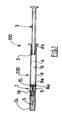
- an injection device 100 comprising a storing device 200 and a needle assembly 1 according to the invention.
- the storing device 200 comprises a barrel 8 having a substantially tubular shape.
- the barrel 8 may be made of a material selected from the group comprising polypropylene, polycycloolefins and/or combinations thereof. Such materials are preferred since they are compatible with long term product storage. Moreover, they usually are transparent and therefore allow a good visual evaluation of the quantity and quality of product stored.
- the barrel 8 has a distal end 8a and a proximal end 8b and it defines a chamber 9 which receives a product 4.
- the product 4 may be any product that is suitable for an injection to a patient, such as a medicine.
- the product 4 is stored within the storing device 200 before it is injected.
- the injection device 100 of figure 1 also comprises a piston 2 which is intended to expel the product 4 through the distal end 8a of the barrel 8 under a distal force exerted on said piston 2 and movement of the piston 2 along an injection stroke, for example in order to inject the product 4.
- the piston 2 of the injection device 100 of figure 1 is fixed, for instance by screwing, to the distal end of a hollow plunger rod 3 which can be manually driven for causing said piston 2 to move in the distal direction in order to inject the product 4.
- the piston 2 could be snapped on the distal end of the plunger rod 3.
- the storing device 200 may be prefilled with the product 4 and the piston 2 seals the proximal end 8b of the barrel 8.
- the piston 2 is a self standing piston.
- the piston 2 is on its own and is not linked to any driven means such as a plunger rod.
- the self standing piston 2 is deformable and it may be inserted in the barrel 8 by means of a vent tube (not shown), that radially compresses it. Once it is introduced in the barrel 8 and exits the vent tube, the radial pressure is released and the self standing piston 2 expands until it stands naturally still by friction of its side faces against the inner walls of the barrel 8. In such a position, the self standing piston 2 seals the proximal end 8b of the barrel 8 and the product 4 may be stored this way for some time.
- the piston 2 whether it be self standing or not, be made from a material with a low water permeation rate expressed and characterized by the water vapour transmission rate that is measured according to the ASTM norm designation E96-93.
- the material can be a rubbery material and is preferably selected from the halobutyl rubbers.
- Halobutyl rubbers are rubbery materials which present a low water permeation rate and they contribute to a better stability of the stored product over time.
- the piston 2 be made of a material with a water permeation rate inferior or equal to 3 g.mm/m 2 .day at room temperature, preferably inferior or equal to 1 g.mm/m 2 .day at room temperature and more preferably inferior or equal to 0.5 g.mm/m 2 .day at room temperature.
- the piston 2 therefore prevents the permeation of water vapour outside.
- Such a piston 2 made of such a material is also very effective in preventing any leakage of product 4 outside the barrel 8.
- the needle assembly 1 comprises a needle hub 6.
- this needle hub 6 has a needle-bearing portion 7, under the form of a tube receiving the needle 5, and a radial wall portion, under the form of a flange 10, linked to the proximal end of the tube receiving the needle 5 by means of a breakable portion 7a, the use of which will be explained later.
- the flange 10 of the needle hub 6 of figures 1-5 appears more clearly on figure 14 which is a perspective view of said needle hub 6 together with the sealings means 15 described hereinbelow.
- the radial wall portion of the needle hub 6 may be under the form of a plurality, four on the example shown on figure 15 , of radial projections 19.
- the needle hub 6 is at least partially made of a rigid material.
- the needle hub 6 is made of a material selected from the group comprising rubbers, thermoplastic polymers such as polypropylene, polyethylene and analogs thereof.
- the needle hub 6, as well as the needle-bearing portion 7, are made of polypropylene and show a hardness equal or more than 50 Shore D.
- the needle assembly 1 also comprises a sealing means, under the form of a plug 15 in the example shown, designed for tightly sealing the distal end 9a of the chamber 9 to the needle-bearing portion 7 of the needle-hub 6.
- the plug 15 is deformable and made of a rubbery material, and more preferably said rubbery material is selected from the group comprising rubbers, thermoplastic elastomers, any combination and analogs thereof.
- the plug 15 is made of an olefin based thermoplastic elastomer and it shows a hardness ranging from 30 to 80 Shore A.
- the needle hub 6, including the needle-bearing portion 7, and the plug 15 are therefore made of two different materials having different hardness and rigidity characteristics.
- the hardness and rigidity of the first material, constituting the needle hub 6 and the needle-bearing portion 7, is higher than the hardness and rigidity of the second material, constituting the plug 15. This difference of hardness and rigidity characteristics allows each element, the needle bearing portion 7 on one side and the plug 15 on the other side to perform its own function in an optimal way.
- the sealing means 15 of needle assembly of the invention allows to avoid the leakage of the injection product 4 from the distal end 9a of the chamber 9 in which said product 4 is stored in the exposed position, as shown on figures 2 , to the needle-bearing portion 7. This sealing means 15 therefore reduces product 4 permeation. Additionally, the sealing means 15 allows to prevent contamination from the outside to the product 4 in the chamber 9.
- the sealing means 15 is made of a material with a water permeation rate inferior or equal to 3 g.mm/m 2 .day at room temperature, preferably inferior or equal to 1 g.mm/m 2 .day at room temperature and more preferably inferior or equal to 0.5 g.mm/m 2 .day at room temperature.
- a sealing means 15 allows therefore the long term storage of the product 4.
- the product 4 may be stored for a long term with an excellent stability.
- the sealing means 15 and the needle hub 6 are physically linked to each other so as to avoid any leakage of product 4 in-between their respective interfaces.
- the plug 15 and the needle hub 6 are coinjected parts. The leakage of the product 4 at the interfaces of the two parts, that is to say the plug 15 on one hand, and the needle hub 6 on the other hand is therefore avoided.
- the needle assembly 1 also comprises a nose 18 which is adapted at the distal end 8a of the barrel 8.
- This nose 18 receives, in the exposed position of the needle 5 as shown on figures 2 to 4 , the needle-bearing portion 7, the breakable portion 7a and the sealing means 15.
- the nose 18 comprises, on its inner wall, an annular ridge 11 forming an abutment.
- This annular ridge 11 forms, together with the distal end 8a of the barrel 8, an annular groove 14 in which the flange 10 of the needle hub 6 is snapped, in the exposed position as shown on figures 2 and 3 .
- the distal end 8a of the barrel 8, the flange 10 of the needle hub 6, the nose 18 and its annular ridge 11 therefore form altogether engaging means designed for securing the needle hub 6 to the distal end 8a of the barrel 8 in the exposed position.
- the barrel 8 may comprise a radial wall portion designed to be snapped in an annular groove of the engaging means.
- the needle hub 6 may comprise an annular groove defining on its inner wall an abutment designed to receive a radial wall portion designed on the inner wall of the barrel 8. Such an embodiment also ensures the securing of the needle hub 6 to the distal end 8a of the barrel 8 in the exposed position.
- the breakable portion 7a of the needle hub 6 is located between the engaging means 8a, 10, 11, 18 and the needle-bearing portion 7.
- This needle-bearing portion 7 is movable between the exposed position of the needle 5, shown on figures 2 and 3 and the retracted position, shown on figure 5 , in which said needle 5 is hidden in the barrel 8.
- the breakable portion 7a is arranged to, when broken, allow independent proximal displacement of said needle-bearing portion 7 relative to said engaging means 8a, 10, 11, 18 between said exposed and said retracted positions of the needle 5.
- the breakable portion 7a and the sealing means 15 are combined, ie they form one single element, yet having different hardness and rigidity characteristics.
- the needle assembly 1 of figures 2-5 further comprises a sleeve 17 which receives the tube receiving the needle 5 of the needle-bearing portion 7 of the needle hub 6.
- This sleeve 17 comprises at its proximal end cutting surfaces 16 which are oriented toward the breakable portion 7a and designed to be fixedly positioned compared to said needle-bearing portion 7 in the exposed position. These cutting surfaces 16 form severing means of the breakable portion 7a.
- a helical spring 12 is located between the sleeve 17 and the needle-bearing portion 7, the proximal end of said spring 12 bearing on the breakable portion 7a and the distal end of said spring 12 bearing on a radial stop 13 defined on the inner wall of the distal region of the nose 18.
- the needle assembly 1 of the invention described above comprises a needle 5 which is in the exposed position.
- the needle assembly 1 further comprises a needle cover 24 in order to protect the needle 5.
- the needle cover 24 preferably comprises a rubber plug that maintains the sterility of the needle 5 and prevents product 4 leakage from the chamber 9 and through the passage way defined by the needle 5.
- the spring 12 In this position, the spring 12 is in a compressed state and it therefore constitutes urging means placed between the engaging means 8a, 10, 11, 18 and the needle-bearing portion 7 and designed to tend to move said needle-bearing portion 7 apart from said engaging means 8a, 10, 11, 18 in the proximal direction: in the position shown on figures 1 and 2 though, this urging means is not activated.
- the user removes the needle cover 24 and proceeds to the injection phase by exerting a distal force on the plunger rod 3 so as to cause the piston 2 to move toward the distal end of the nedle assembly 1 and realize the injection of the product 4.
- the breakable portion 7a is designed to be distally movable by the piston 2 at the end of injection, in particular under the effect of an additional distal force exerted on said piston 2 at the end of injection. This additional force is necessary for disengaging the flange 10 of the needle hub 6 from the engaging means 8a, 11 and allowing the distal displacement of the breakable portion 7a. This additional force is high enough to prevent premature activation of the severing means 16. It is to be noted that the engaging means 8a, 10, 11, 18 are designed to prevent any premature activation of the system upon pressure build up inside the chamber 9. They are also set to provide acceptable, ie sufficient enough but not too high, force to activate the safety system described herein.
- the user therefore pushes further on the plunger rod 3, causing the piston 2 to move distally the breakable portion 7a until said breakable portion 7a comes in contact with the cutting surfaces 16 of the sleeve 17.
- the cutting surfaces 16 act as severing means which break the breakable portion 7a as said breakable portion 7a moves distally, as shown on figure 4 .
- the sealing means, ie the plug 15, and then the piston 2 itself are successively cut by the cutting surfaces 16 as shown on figure 4 . Therefore, once broken, the breakable portion 7a allows the independent proximal displacement of the barrel 8.
- the proximal end of the spring 12 is by way of consequence no more retained by the breakable portion 7a and said spring 12 then aims at returning to its rest position: it expands in the proximal direction, drawing with him the needle-bearing portion 7 and the needle 5.
- the needle 5 is therefore drawn together with the needle-bearing portion 7 inside the plunger rod 3 as shown on figure 5 .
- the needle 5 is eventually in the retracted position. In this position, the device 100 is safe.
- the needle 5 is no more exposed and accidental pricking is prevented.
- the injection device 100 may be disposed.
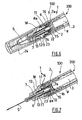
- FIG. 6 and 7 is shown a variant of the needle assembly 1 shown on figures 1 to 5 , in which the sealing means 15 comprise a longitudinal skirt 22 extending in the distal direction.
- the references designating the same elements as in figures 1-5 have been maintained.
- the skirt 22 receives part of the proximal region of the needle hub 6 and it is designed to fixedly being received in the distal end 8a of the barrel 8.
- the skirt 22 comprises at its distal end a radial wall portion 23 which, in the exposed position shown on figure 6 , is snapped in an annular groove 14 formed by the distal end 8a of the barrel and an annular ridge 11 defined on the inner wall of the nose 18.
- the radial wall portion 23, the distal end 8a of the barrel 8, the annular ridge 11 and the nose 18 therefore form engaging means that secure the needle hub 6 to the distal end 8a of the barrel 8 in the exposed position.
- part of the engaging means and the sealing means are combined.
- the skirt 22 and its radial wall portion 23 are made of a deformable material.
- the skirt 22 is therefore able to fold back on itself from the exposed position shown on figure 6 to an activation position, or cutting position, shown on figure 7 .
- the piston 2 under the effect of a distal force exerted on the plunger rod 3, has moved distally the breakable portion 7a of the needle hub 6 until it is in contact with the cutting surfaces 16 of the sleeve 17.
- the skirt 22 has started to fold back on itself, providing a soft friction force for the user to overcome while exerting a distal force on the plunger rod 3 and in consequence providing a damping of said distal force allowing a better control of the displacement of the piston 2.
- the cutting surfaces 16 sever the breakable portion 7a, then cut the sealing means 15 and finally the piston 2, while the skirt 22 completely folds back on itself as shown on figure 7 .
- the final position following the one shown on figure 7 is not shown. It corresponds to the retracted position, where the needle 5 is hidden within the plunger rod 3 after the spring 12 has returned to its rest position, drawing with him the needle-bearing portion 7 and the needle 5 in the proximal direction.
- the skirt 22 may extend in the proximal direction.
- FIG. 10 and 11 is shown a variant of the embodiment of figures 6 and 7 , wherein the skirt 22 does not fold back on itself but is provided, on its outer wall, with an annular projection 27 which, in the exposed position, as shown on figure 10 , is snapped between the proximal end of the nose 18 and an abutment 28 defined on the inner wall of the barrel 8.
- the references designating the same elements as in figures 1-7 have been maintained
- FIGS 8 and 9 is shown a variant of the needle assembly 1 of the invention, wherein the engaging means comprise a radial wall portion designed to be snapped in an annular groove 14 at least partly defined by the barrel 8, in the exposed position, said radial wall portion being a plurality of radial projections defined on the needle hub 6 and where the radial projections form the distal ends 20 of a plurality of longitudinal flexible legs 21 extending in the distal direction.
- the references designating the same elements as in figures 1-5 have been maintained.
- the radial projections form the proximal ends of a plurality of longitudinal flexible legs extending in the proximal direction.
- the ends 20 are made of a deformable material.
- the ends 20 are snapped in an annular groove 14 formed by an annular ridge 11 defined on said nose 18 and the distal end 8a of the barrel 8.
- the ends 20, the annular ridge 11, the distal end 8a of the barrel 8 and the nose 18 therefore form engaging means that secure the needle hub 6 to the distal end 8a of the barrel 8 in the exposed position.
- the figure 9 shows the embodiment of figure 8 in the cutting position, once the ends 20 of the longitudinal flexible legs 21 have overcome the annular ridge 11 under the distal pressure of the piston 2 pushed distally by the distal force exerted by the user on the plunger rod 3.
- the cutting surfaces 16 of the sleeve 17 then break the breakable portion 7a, cut the sealing means 15 and the piston 2.
- the needle 5 is then drawn within the plunger rod 3 by action of the spring 12 which returns to its rest position, as described in the previous embodiments above.
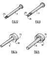
- a plunger rod 3 suitable as a driven means for causing the piston 2 of the injection devices 100 of figures 1-11 to move toward the distal end of the needle assembly 1 of said injection device 100 and inject the product 4.
- the plunger rod 3 is hollow and designed to receive the needle 5 in the retracted position, as already shown for instance on figure 5 .
- the distal end 25 of said plunger rod 3 is open.
- FIG 13 is shown a variant of the hollow plunger rod 3 of figure 12 , wherein the distal end 25 of said plunger rod 3 comprises supporting means designed to form a radial bearing surface for the piston 2 to prevent said piston 2 from deforming itself in said plunger rod 3 as the severing means 16 cut said piston 2 under the effect of the distal force exerted on said plunger rod 3 at the end of injection.
- the supporting means also help providing a clean cut of the piston 2 and therefore a good passage through for the needle 5.
- the supporting means comprise a radial wall portion 26, which, on this example, defines a plurality of radial extensions forming a cross. After having cut the breakable portion 7a, the sealing means 15 and the piston 2, the cutting surfaces 16 of the severing means also cut these radial extensions and the needle 5 is allowed to withdraw within the plunger rod 3.
- the needle assembly 1 of the invention allows the manufacture of prefillable injection devices 100 with an integrated safety system.
- the injection devices 100 of the invention are therefore safe, compact and easy to handle, both as a final product by the end-users, such as nurses, and as a manufacturing product by the pharmaceutical companies for instance, during the filling and/or stoppering processes.
Claims (27)
- Dispositif d'injection (100) d'un produit (4) comprenant un dispositif de stockage (200) et un ensemble d'aiguille (1) devant être utilisé en combinaison avec le dispositif de stockage (200), ledit dispositif de stockage (200) comprenant au moins :- un cylindre (8) de forme essentiellement tubulaire ayant une extrémité distale (8a) et une extrémité proximale (8b), ledit cylindre (8) définissant une chambre (9) pour recevoir ledit produit (4),- un piston (2) destiné à expulser ledit produit (4) à travers l'extrémité distale (8a) sous une force distale exercée sur ledit piston (2), ledit dispositif de stockage (200) pouvant être prérempli avec ledit produit (4) et ledit piston (2) scellant l'extrémité proximale (8b) dudit cylindre (8),ledit ensemble d'aiguille (1) comprenant au moins :- une partie de support d'aiguille (7), conçue pour recevoir une aiguille (5) et pouvant se déplacer entre une position exposée dans laquelle ladite aiguille (5) est exposée et une position rétractée dans laquelle l'aiguille (5) est cachée dans ledit cylindre (8), ladite partie de support d'aiguille (7) étant supportée par un raccord d'aiguille (6), ledit raccord d'aiguille (6) et la partie de support d'aiguille (7) étant réalisés en un premier matériau,- un moyen d'engagement (8a, 10, 11, 18, 19, 20, 23), conçu pour fixer ladite partie de support d'aiguille (7) à ladite extrémité distale (8a) dudit cylindre (8), au moins dans la position exposée,caractérisé en ce que :ledit ensemble d'aiguille comprend :- un moyen d'étanchéité (15) conçu pour sceller de manière étanche l'extrémité distale (9a) de ladite chambre (9) à ladite partie de support d'aiguille (7) de manière à éviter toute fuite dudit produit injectable (4) à partir de l'extrémité distale (9a) de ladite chambre (9) à la partie de support d'aiguille (7), au moins dans la position exposée, et réduire la perméation de produit, ledit moyen d'étanchéité (15) étant réalisé en un deuxième matériau ;- une partie cassable (7a) située entre ledit moyen d'engagement (8a, 10, 11, 18, 19, 20, 23) et ladite partie de support d'aiguille (7), ladite partie cassable (7a) étant agencée pour, lorsqu'elle est cassée, permettre le déplacement proximal indépendant de ladite partie de support d'aiguille (7) par rapport audit moyen d'engagement (8a, 10, 11, 18, 19, 20, 23) entre lesdites positions exposée et rétractée,- ledit premier matériau étant plus rigide que ledit deuxième matériau, et- ledit dispositif d'injection comprend en outre un moyen entraîné (3) pour amener ledit piston (2) à se déplacer vers l'extrémité distale dudit ensemble d'aiguille (1) et réaliser l'injection du produit (4), ledit moyen entraîné comprenant une tige de plongeur creuse (3) conçue pour recevoir au moins ladite aiguille (5) dans sa position rétractée.
- Dispositif d'injection (100) selon la revendication 1, dans lequel ledit premier matériau présente une dureté supérieure ou égale à 50 Shore D.
- Dispositif d'injection (100) selon la revendication 2, dans laquelle ladite dureté est supérieure ou égale à 60 Shore D.
- Dispositif d'injection (100) selon la revendication 1, dans lequel ledit deuxième matériau présente une dureté se trouvant dans une plage allant de 30 à 80 Shore A.
- Dispositif d'injection (100) selon la revendication 4, dans lequel ladite dureté se trouve dans une plage allant de 45 à 70 Shore A.
- Dispositif d'injection (100) selon la revendication 1, dans lequel le moyen d'étanchéité comprend au moins un bouchon (15) réalisé au moins partiellement en un matériau caoutchouteux choisi dans le groupe comprenant les caoutchoucs, les élastomères thermoplastiques, et toute combinaison et analogues de ceux-ci.
- Dispositif d'injection (100) selon la revendication précédente, dans lequel le matériau caoutchouteux est un élastomère thermoplastique à base d'oléfine.
- Dispositif d'injection (100) selon la revendication 1, dans lequel le raccord d'aiguille (6) et la partie de support d'aiguille (7) sont réalisés au moins partiellement en un matériau choisi dans le groupe comprenant les caoutchoucs, les polymères thermoplastiques tels que le polypropylène, le polyéthylène, et toute combinaison et analogues de ceux-ci.
- Dispositif d'injection (100) selon la revendication 8, dans lequel le raccord d'aiguille (6) et la partie de support d'aiguille (7) sont réalisés en polypropylène.
- Dispositif d'injection (100) selon l'une des revendications précédentes, dans lequel le moyen d'étanchéité (15) et le raccord d'aiguille (6), comportant la partie de support d'aiguille (7), sont physiquement reliés l'un à l'autre de manière à éviter toute fuite de produit (4) entre leurs interfaces respectives.
- Dispositif d'injection (100) selon la revendication précédente, dans lequel le moyen d'étanchéité (15) et le raccord d'aiguille (6), comportant la partie de support d'aiguille (7), sont des parties co-injectées.
- Dispositif d'injection (100) selon la revendication 1, dans lequel ladite partie cassable (7a) et ledit moyen d'étanchéité (15) sont combinés.
- Dispositif d'injection (100) selon la revendication 1, dans lequel ledit moyen d'engagement et ledit moyen d'étanchéité (15) sont combinés.
- Dispositif d'injection (100) selon l'une des revendications 1 à 9, dans lequel ledit moyen d'étanchéité (15) est réalisé en un matériau avec une vitesse de perméation d'eau inférieure ou égale à 3 g.mm/m2.jour à température ambiante, de préférence inférieure ou égale à 1 g.mm/m2.jour à température ambiante et plus préférablement inférieure ou égale à 0,5 g.mm/m2.jour à température ambiante, mesurée selon la procédure « A » de la norme E 96-93 de l'ASTM.
- Dispositif d'injection (100) selon la revendication 1, dans lequel :- au moins ladite partie cassable (7a) est conçue pour pouvoir se déplacer de manière distale par ledit piston (2) à la fin d'une course d'injection, et- ledit ensemble d'aiguille (1) comprend un moyen de rupture (16) orienté vers ladite partie cassable (7a) et conçu pour être positionné de manière fixe par rapport à ladite partie de support d'aiguille (7) dans la position exposée, et agencé pour rompre ladite partie cassable (7a) lorsqu'elle se déplace de manière distale et ensuite pour permettre un déplacement proximal de la partie de support d'aiguille (7).
- Dispositif d'injection (100) selon l'une des revendications précédentes, dans lequel ledit moyen d'engagement comprend une partie de paroi radiale (10, 19, 20, 23) conçue pour être encliquetée dans une rainure annulaire (14) au moins partiellement formée sur ledit cylindre (8), dans la position exposée.
- Dispositif d'injection (100) selon la revendication précédente, dans lequel ladite partie de paroi radiale (19, 20, 23) est réalisée en un matériau déformable.
- Dispositif d'injection (100) selon la revendication 16, dans lequel ladite partie de paroi radiale est une bride (10) définie sur le raccord d'aiguille (6).
- Dispositif d'injection (100) selon la revendication 17, dans lequel ladite partie de paroi radiale est une pluralité de saillies radiales (19, 20) définies sur le raccord d'aiguille (6).
- Dispositif d'injection (100) selon la revendication précédente, dans lequel les saillies radiales forment les extrémités distales et/ou proximales (20) d'une pluralité de pattes flexibles longitudinales (21) s'étendant respectivement dans la direction distale et/ou la direction proximale.
- Dispositif d'injection (100) selon la revendication 1, dans lequel ledit moyen d'étanchéité comprend une jupe longitudinale (22) s'étendant dans la direction distale, respectivement, proximale, ladite jupe (22) recevant une partie de la région proximale dudit raccord d'aiguille (6) et étant reçue de manière fixe dans ladite extrémité distale (8a) dudit cylindre (8).
- Dispositif d'injection (100) selon la revendication précédente, dans lequel ladite jupe (22) est capable de se replier sur elle-même à partir de la position exposée à une position d'activation.
- Dispositif d'injection (100) selon la revendication 15, dans lequel le moyen de rupture comprend au moins des surfaces de coupe (16) conçues au niveau de l'extrémité proximale d'un manchon (17) recevant une partie de la partie de support d'aiguille (7) dudit raccord d'aiguille (6).
- Dispositif d'injection (100) selon la revendication 1, comprenant un moyen de sollicitation (12) placé entre ledit moyen d'engagement (8a, 10, 11, 18, 19, 20, 23) et ladite partie de support d'aiguille (7) et conçu de manière à avoir tendance à éloigner ladite partie de support d'aiguille (7) dudit moyen d'engagement (8a, 10, 11, 18, 19, 20, 23) dans la direction proximale.
- Dispositif d'injection (100) selon l'une des revendications précédentes, comprenant en outre un nez (18) conçu pour être adapté au niveau de l'extrémité distale (8a) du cylindre (8) et pour recevoir, au moins dans la position exposée, ladite partie de support d'aiguille (7), ladite partie cassable (7a) et ledit moyen d'étanchéité (15).
- Dispositif d'injection (100) selon l'une des revendications précédentes, comprenant en outre une aiguille (5).
- Dispositif d'injection (100) selon l'une des revendications précédentes, comprenant en outre un étui protecteur d'aiguille (24).
Applications Claiming Priority (2)
| Application Number | Priority Date | Filing Date | Title |
|---|---|---|---|
| FR0603720A FR2900344B1 (fr) | 2006-04-26 | 2006-04-26 | Dispositif d'injection avec aiguille retractable |
| PCT/IB2007/001980 WO2007125419A2 (fr) | 2006-04-26 | 2007-04-26 | Dispositif d'injection à aiguille rétractable |
Publications (2)
| Publication Number | Publication Date |
|---|---|
| EP2012855A2 EP2012855A2 (fr) | 2009-01-14 |
| EP2012855B1 true EP2012855B1 (fr) | 2015-11-11 |
Family
ID=37695898
Family Applications (1)
| Application Number | Title | Priority Date | Filing Date |
|---|---|---|---|
| EP07734992.6A Active EP2012855B1 (fr) | 2006-04-26 | 2007-04-26 | Dispositif d'injection à aiguille rétractable |
Country Status (7)
| Country | Link |
|---|---|
| US (1) | US9259537B2 (fr) |
| EP (1) | EP2012855B1 (fr) |
| JP (1) | JP5373600B2 (fr) |
| CN (1) | CN101466425B (fr) |
| ES (1) | ES2560640T3 (fr) |
| FR (1) | FR2900344B1 (fr) |
| WO (1) | WO2007125419A2 (fr) |
Families Citing this family (21)
| Publication number | Priority date | Publication date | Assignee | Title |
|---|---|---|---|---|
| US8808246B2 (en) | 2009-07-21 | 2014-08-19 | The General Hospital Corporation | Peripheral blood sampling methods and devices |
| US8323249B2 (en) | 2009-08-14 | 2012-12-04 | The Regents Of The University Of Michigan | Integrated vascular delivery system |
| WO2011146772A1 (fr) | 2010-05-19 | 2011-11-24 | Tangent Medical Technologies Llc | Système d'aiguille de sécurité utilisable avec dispositif médical |
| WO2011146769A2 (fr) | 2010-05-19 | 2011-11-24 | Tangent Medical Technologies Llc | Système intégré d'administration vasculaire |
| US9186100B2 (en) | 2011-04-26 | 2015-11-17 | Velano Vascular, Inc. | Systems and methods for phlebotomy through a peripheral IV catheter |
| US10076272B2 (en) | 2011-04-26 | 2018-09-18 | Velano Vascular, Inc. | Systems and methods for phlebotomy through a peripheral IV catheter |
| US8366685B2 (en) | 2011-04-26 | 2013-02-05 | Creative Vascular, Llc | Systems and methods for phlebotomy through a peripheral IV catheter |
| ITMI20120016A1 (it) * | 2012-01-09 | 2013-07-10 | Biosynth Srl | Siringa per iniezioni o prelievi |
| WO2015065942A1 (fr) * | 2013-10-28 | 2015-05-07 | Becton, Dickinson And Company | Bouchon étanche pour ensemble seringue à faibles forces de décollement et de retenue |
| WO2015119940A1 (fr) | 2014-02-04 | 2015-08-13 | Icu Medical, Inc. | Systèmes et procédés d'auto-amorçage |
| US10232110B2 (en) * | 2014-07-08 | 2019-03-19 | Becton, Dickinson And Company | Fluid transfer device or set with retractable needle and septum |
| US20180133375A1 (en) * | 2014-10-30 | 2018-05-17 | Chugai Seiyaku Kabushiki Kaisha | Pre-Filled Syringe Formulation With Needle, Which Is Equipped With Syringe Cap |
| EP3275485A4 (fr) * | 2015-03-26 | 2018-06-27 | Terumo Kabushiki Kaisha | Obturateur de seringue, ensemble seringue, et seringue pré-remplie |
| US10369292B2 (en) * | 2016-01-15 | 2019-08-06 | W. L. Gore & Associates, Inc. | Syringe plunger assemblies |
| US10300247B2 (en) | 2016-02-03 | 2019-05-28 | Velano Vascular, Inc. | Devices and methods for fluid transfer through a placed peripheral intravenous catheter |
| FR3052690B1 (fr) * | 2016-06-20 | 2018-06-22 | Aptar France Sas | Dispositif de distribution de produit fluide. |
| US9744344B1 (en) | 2016-06-30 | 2017-08-29 | Velano Vascular, Inc. | Devices and methods for catheter placement within a vein |
| EP3600516A4 (fr) | 2017-03-21 | 2021-01-20 | Velano Vascular, Inc. | Dispositifs et procédés de transfert de fluide à travers un cathéter intraveineux périphérique posé |
| US10773056B2 (en) | 2017-03-21 | 2020-09-15 | Velano Vascular, Inc. | Systems and methods for controlling catheter device size |
| CN114599419A (zh) | 2019-08-20 | 2022-06-07 | 威蓝诺血管股份有限公司 | 具有延长导管的流体输送装置及其使用方法 |
| CA3197752A1 (fr) | 2020-11-26 | 2022-06-02 | Avia Vascular, Llc | Dispositifs, systemes et procedes de prelevement sanguin |
Family Cites Families (9)
| Publication number | Priority date | Publication date | Assignee | Title |
|---|---|---|---|---|
| US5578011A (en) * | 1995-05-11 | 1996-11-26 | Shaw; Thomas J. | Tamperproof retractable syringe |
| US5632733A (en) * | 1995-05-11 | 1997-05-27 | Shaw; Thomas J. | Tamperproof retractable syringe |
| JP3835882B2 (ja) * | 1997-03-31 | 2006-10-18 | テルモ株式会社 | 留置針組立体 |
| AU723060B3 (en) * | 2000-02-22 | 2000-08-17 | Occupational & Medical Innovations Ltd | A single use syringe |
| US6689106B2 (en) * | 2000-07-31 | 2004-02-10 | Becton Dickinson And Company | Retracting needle assembly for a syringe |
| FR2839892B1 (fr) * | 2002-05-27 | 2005-03-18 | Mb Innovation | Dispositif d'injection a usage unique destine a etre pre-rempli |
| CA2412409C (fr) * | 2002-11-20 | 2007-01-23 | Ming-Jeng Shue | Seringue jetable |
| US7604613B2 (en) * | 2004-01-20 | 2009-10-20 | Beckton, Dickinson And Company | Syringe having a retractable needle |
| CA2584106C (fr) * | 2004-10-14 | 2011-09-06 | Safety Medical International, Incorporated | Seringue medicale de securite a aiguille retractable |
-
2006
- 2006-04-26 FR FR0603720A patent/FR2900344B1/fr active Active
-
2007
- 2007-04-26 JP JP2009507194A patent/JP5373600B2/ja active Active
- 2007-04-26 WO PCT/IB2007/001980 patent/WO2007125419A2/fr active Application Filing
- 2007-04-26 ES ES07734992.6T patent/ES2560640T3/es active Active
- 2007-04-26 US US12/298,647 patent/US9259537B2/en active Active
- 2007-04-26 CN CN200780021670XA patent/CN101466425B/zh active Active
- 2007-04-26 EP EP07734992.6A patent/EP2012855B1/fr active Active
Also Published As
| Publication number | Publication date |
|---|---|
| JP5373600B2 (ja) | 2013-12-18 |
| US9259537B2 (en) | 2016-02-16 |
| WO2007125419A2 (fr) | 2007-11-08 |
| EP2012855A2 (fr) | 2009-01-14 |
| CN101466425A (zh) | 2009-06-24 |
| US20110015577A1 (en) | 2011-01-20 |
| FR2900344B1 (fr) | 2009-02-27 |
| CN101466425B (zh) | 2013-01-23 |
| JP2009534152A (ja) | 2009-09-24 |
| FR2900344A1 (fr) | 2007-11-02 |
| WO2007125419A3 (fr) | 2008-01-24 |
| ES2560640T3 (es) | 2016-02-22 |
Similar Documents
| Publication | Publication Date | Title |
|---|---|---|
| EP2012855B1 (fr) | Dispositif d'injection à aiguille rétractable | |
| JP6731999B2 (ja) | 針交換装置 | |
| US10286160B2 (en) | Dual chamber passive retraction needle syringe | |
| US7976510B2 (en) | Syringe with adjustable two piece plunger rod | |
| CA2315898C (fr) | Technique de fabrication d'une seringue a aiguille retractable | |
| DK2734255T3 (en) | Auto-injector for returnable syringe filled beforehand | |
| TWI587887B (zh) | 回縮針安全性注射器 | |
| EP2453957B1 (fr) | Dispositif d'injection à raccord luer étanche | |
| US20080183140A1 (en) | Syringe cartridge system | |
| US20010053886A1 (en) | Retracting needle syringe | |
| US20140171901A1 (en) | Device for retaining and storing liquid media and method of expelling the liquid media | |
| CN111617342A (zh) | 具有滚动膜片的注射器 | |
| CN105939742A (zh) | 组合式药筒和针组件 | |
| US8632519B2 (en) | Syringe having a collapsible plunger rod | |
| EP1218046B1 (fr) | Seringue a aiguille retractable |
Legal Events
| Date | Code | Title | Description |
|---|---|---|---|
| PUAI | Public reference made under article 153(3) epc to a published international application that has entered the european phase |
Free format text: ORIGINAL CODE: 0009012 |
|
| 17P | Request for examination filed |
Effective date: 20081113 |
|
| AK | Designated contracting states |
Kind code of ref document: A2 Designated state(s): AT BE BG CH CY CZ DE DK EE ES FI FR GB GR HU IE IS IT LI LT LU LV MC MT NL PL PT RO SE SI SK TR |
|
| AX | Request for extension of the european patent |
Extension state: AL BA HR MK RS |
|
| RIN1 | Information on inventor provided before grant (corrected) |
Inventor name: NEALE, KEVIN DAVID Inventor name: PEROT, FREDERIC Inventor name: BANEY, BRUNO |
|
| DAX | Request for extension of the european patent (deleted) | ||
| GRAP | Despatch of communication of intention to grant a patent |
Free format text: ORIGINAL CODE: EPIDOSNIGR1 |
|
| INTG | Intention to grant announced |
Effective date: 20150603 |
|
| GRAS | Grant fee paid |
Free format text: ORIGINAL CODE: EPIDOSNIGR3 |
|
| GRAA | (expected) grant |
Free format text: ORIGINAL CODE: 0009210 |
|
| AK | Designated contracting states |
Kind code of ref document: B1 Designated state(s): AT BE BG CH CY CZ DE DK EE ES FI FR GB GR HU IE IS IT LI LT LU LV MC MT NL PL PT RO SE SI SK TR |
|
| REG | Reference to a national code |
Ref country code: GB Ref legal event code: FG4D |
|
| REG | Reference to a national code |
Ref country code: CH Ref legal event code: EP |
|
| REG | Reference to a national code |
Ref country code: IE Ref legal event code: FG4D |
|
| REG | Reference to a national code |
Ref country code: AT Ref legal event code: REF Ref document number: 760140 Country of ref document: AT Kind code of ref document: T Effective date: 20151215 |
|
| REG | Reference to a national code |
Ref country code: DE Ref legal event code: R096 Ref document number: 602007043859 Country of ref document: DE |
|
| REG | Reference to a national code |
Ref country code: ES Ref legal event code: FG2A Ref document number: 2560640 Country of ref document: ES Kind code of ref document: T3 Effective date: 20160222 |
|
| REG | Reference to a national code |
Ref country code: LT Ref legal event code: MG4D |
|
| REG | Reference to a national code |
Ref country code: NL Ref legal event code: MP Effective date: 20160211 |
|
| REG | Reference to a national code |
Ref country code: FR Ref legal event code: PLFP Year of fee payment: 10 |
|
| REG | Reference to a national code |
Ref country code: AT Ref legal event code: MK05 Ref document number: 760140 Country of ref document: AT Kind code of ref document: T Effective date: 20151111 |
|
| PG25 | Lapsed in a contracting state [announced via postgrant information from national office to epo] |
Ref country code: NL Free format text: LAPSE BECAUSE OF FAILURE TO SUBMIT A TRANSLATION OF THE DESCRIPTION OR TO PAY THE FEE WITHIN THE PRESCRIBED TIME-LIMIT Effective date: 20151111 Ref country code: LT Free format text: LAPSE BECAUSE OF FAILURE TO SUBMIT A TRANSLATION OF THE DESCRIPTION OR TO PAY THE FEE WITHIN THE PRESCRIBED TIME-LIMIT Effective date: 20151111 Ref country code: IS Free format text: LAPSE BECAUSE OF FAILURE TO SUBMIT A TRANSLATION OF THE DESCRIPTION OR TO PAY THE FEE WITHIN THE PRESCRIBED TIME-LIMIT Effective date: 20160311 |
|
| PG25 | Lapsed in a contracting state [announced via postgrant information from national office to epo] |
Ref country code: PT Free format text: LAPSE BECAUSE OF FAILURE TO SUBMIT A TRANSLATION OF THE DESCRIPTION OR TO PAY THE FEE WITHIN THE PRESCRIBED TIME-LIMIT Effective date: 20160311 Ref country code: PL Free format text: LAPSE BECAUSE OF FAILURE TO SUBMIT A TRANSLATION OF THE DESCRIPTION OR TO PAY THE FEE WITHIN THE PRESCRIBED TIME-LIMIT Effective date: 20151111 Ref country code: LV Free format text: LAPSE BECAUSE OF FAILURE TO SUBMIT A TRANSLATION OF THE DESCRIPTION OR TO PAY THE FEE WITHIN THE PRESCRIBED TIME-LIMIT Effective date: 20151111 Ref country code: AT Free format text: LAPSE BECAUSE OF FAILURE TO SUBMIT A TRANSLATION OF THE DESCRIPTION OR TO PAY THE FEE WITHIN THE PRESCRIBED TIME-LIMIT Effective date: 20151111 Ref country code: SE Free format text: LAPSE BECAUSE OF FAILURE TO SUBMIT A TRANSLATION OF THE DESCRIPTION OR TO PAY THE FEE WITHIN THE PRESCRIBED TIME-LIMIT Effective date: 20151111 Ref country code: FI Free format text: LAPSE BECAUSE OF FAILURE TO SUBMIT A TRANSLATION OF THE DESCRIPTION OR TO PAY THE FEE WITHIN THE PRESCRIBED TIME-LIMIT Effective date: 20151111 Ref country code: GR Free format text: LAPSE BECAUSE OF FAILURE TO SUBMIT A TRANSLATION OF THE DESCRIPTION OR TO PAY THE FEE WITHIN THE PRESCRIBED TIME-LIMIT Effective date: 20160212 |
|
| PG25 | Lapsed in a contracting state [announced via postgrant information from national office to epo] |
Ref country code: CZ Free format text: LAPSE BECAUSE OF FAILURE TO SUBMIT A TRANSLATION OF THE DESCRIPTION OR TO PAY THE FEE WITHIN THE PRESCRIBED TIME-LIMIT Effective date: 20151111 |
|
| REG | Reference to a national code |
Ref country code: DE Ref legal event code: R097 Ref document number: 602007043859 Country of ref document: DE |
|
| PG25 | Lapsed in a contracting state [announced via postgrant information from national office to epo] |
Ref country code: RO Free format text: LAPSE BECAUSE OF FAILURE TO SUBMIT A TRANSLATION OF THE DESCRIPTION OR TO PAY THE FEE WITHIN THE PRESCRIBED TIME-LIMIT Effective date: 20151111 Ref country code: EE Free format text: LAPSE BECAUSE OF FAILURE TO SUBMIT A TRANSLATION OF THE DESCRIPTION OR TO PAY THE FEE WITHIN THE PRESCRIBED TIME-LIMIT Effective date: 20151111 Ref country code: SK Free format text: LAPSE BECAUSE OF FAILURE TO SUBMIT A TRANSLATION OF THE DESCRIPTION OR TO PAY THE FEE WITHIN THE PRESCRIBED TIME-LIMIT Effective date: 20151111 Ref country code: BE Free format text: LAPSE BECAUSE OF NON-PAYMENT OF DUE FEES Effective date: 20160430 Ref country code: DK Free format text: LAPSE BECAUSE OF FAILURE TO SUBMIT A TRANSLATION OF THE DESCRIPTION OR TO PAY THE FEE WITHIN THE PRESCRIBED TIME-LIMIT Effective date: 20151111 |
|
| PLBE | No opposition filed within time limit |
Free format text: ORIGINAL CODE: 0009261 |
|
| STAA | Information on the status of an ep patent application or granted ep patent |
Free format text: STATUS: NO OPPOSITION FILED WITHIN TIME LIMIT |
|
| 26N | No opposition filed |
Effective date: 20160812 |
|
| PG25 | Lapsed in a contracting state [announced via postgrant information from national office to epo] |
Ref country code: SI Free format text: LAPSE BECAUSE OF FAILURE TO SUBMIT A TRANSLATION OF THE DESCRIPTION OR TO PAY THE FEE WITHIN THE PRESCRIBED TIME-LIMIT Effective date: 20151111 |
|
| REG | Reference to a national code |
Ref country code: CH Ref legal event code: PL |
|
| PG25 | Lapsed in a contracting state [announced via postgrant information from national office to epo] |
Ref country code: BE Free format text: LAPSE BECAUSE OF FAILURE TO SUBMIT A TRANSLATION OF THE DESCRIPTION OR TO PAY THE FEE WITHIN THE PRESCRIBED TIME-LIMIT Effective date: 20151111 Ref country code: LU Free format text: LAPSE BECAUSE OF FAILURE TO SUBMIT A TRANSLATION OF THE DESCRIPTION OR TO PAY THE FEE WITHIN THE PRESCRIBED TIME-LIMIT Effective date: 20160426 |
|
| REG | Reference to a national code |
Ref country code: IE Ref legal event code: MM4A |
|
| PG25 | Lapsed in a contracting state [announced via postgrant information from national office to epo] |
Ref country code: LI Free format text: LAPSE BECAUSE OF NON-PAYMENT OF DUE FEES Effective date: 20160430 Ref country code: CH Free format text: LAPSE BECAUSE OF NON-PAYMENT OF DUE FEES Effective date: 20160430 |
|
| REG | Reference to a national code |
Ref country code: FR Ref legal event code: PLFP Year of fee payment: 11 |
|
| PG25 | Lapsed in a contracting state [announced via postgrant information from national office to epo] |
Ref country code: IE Free format text: LAPSE BECAUSE OF NON-PAYMENT OF DUE FEES Effective date: 20160426 |
|
| REG | Reference to a national code |
Ref country code: FR Ref legal event code: PLFP Year of fee payment: 12 |
|
| PG25 | Lapsed in a contracting state [announced via postgrant information from national office to epo] |
Ref country code: HU Free format text: LAPSE BECAUSE OF FAILURE TO SUBMIT A TRANSLATION OF THE DESCRIPTION OR TO PAY THE FEE WITHIN THE PRESCRIBED TIME-LIMIT; INVALID AB INITIO Effective date: 20070426 Ref country code: CY Free format text: LAPSE BECAUSE OF FAILURE TO SUBMIT A TRANSLATION OF THE DESCRIPTION OR TO PAY THE FEE WITHIN THE PRESCRIBED TIME-LIMIT Effective date: 20151111 |
|
| PG25 | Lapsed in a contracting state [announced via postgrant information from national office to epo] |
Ref country code: MT Free format text: LAPSE BECAUSE OF NON-PAYMENT OF DUE FEES Effective date: 20160430 Ref country code: MC Free format text: LAPSE BECAUSE OF FAILURE TO SUBMIT A TRANSLATION OF THE DESCRIPTION OR TO PAY THE FEE WITHIN THE PRESCRIBED TIME-LIMIT Effective date: 20151111 Ref country code: TR Free format text: LAPSE BECAUSE OF FAILURE TO SUBMIT A TRANSLATION OF THE DESCRIPTION OR TO PAY THE FEE WITHIN THE PRESCRIBED TIME-LIMIT Effective date: 20151111 |
|
| PG25 | Lapsed in a contracting state [announced via postgrant information from national office to epo] |
Ref country code: BG Free format text: LAPSE BECAUSE OF FAILURE TO SUBMIT A TRANSLATION OF THE DESCRIPTION OR TO PAY THE FEE WITHIN THE PRESCRIBED TIME-LIMIT Effective date: 20151111 |
|
| PGFP | Annual fee paid to national office [announced via postgrant information from national office to epo] |
Ref country code: FR Payment date: 20230321 Year of fee payment: 17 |
|
| PGFP | Annual fee paid to national office [announced via postgrant information from national office to epo] |
Ref country code: IT Payment date: 20230322 Year of fee payment: 17 |
|
| PGFP | Annual fee paid to national office [announced via postgrant information from national office to epo] |
Ref country code: ES Payment date: 20230502 Year of fee payment: 17 Ref country code: DE Payment date: 20230321 Year of fee payment: 17 |
|
| PGFP | Annual fee paid to national office [announced via postgrant information from national office to epo] |
Ref country code: GB Payment date: 20240320 Year of fee payment: 18 |