EP2012677B1 - Device for inserting securing anchors into human or animal tissue - Google Patents
Device for inserting securing anchors into human or animal tissue Download PDFInfo
- Publication number
- EP2012677B1 EP2012677B1 EP07701322A EP07701322A EP2012677B1 EP 2012677 B1 EP2012677 B1 EP 2012677B1 EP 07701322 A EP07701322 A EP 07701322A EP 07701322 A EP07701322 A EP 07701322A EP 2012677 B1 EP2012677 B1 EP 2012677B1
- Authority
- EP
- European Patent Office
- Prior art keywords
- needle
- securing
- anchor
- securing anchor
- anchors
- Prior art date
- Legal status (The legal status is an assumption and is not a legal conclusion. Google has not performed a legal analysis and makes no representation as to the accuracy of the status listed.)
- Active
Links
Images


Classifications
-
- A—HUMAN NECESSITIES
- A61—MEDICAL OR VETERINARY SCIENCE; HYGIENE
- A61B—DIAGNOSIS; SURGERY; IDENTIFICATION
- A61B17/00—Surgical instruments, devices or methods, e.g. tourniquets
- A61B17/068—Surgical staplers, e.g. containing multiple staples or clamps
- A61B17/0682—Surgical staplers, e.g. containing multiple staples or clamps for applying U-shaped staples or clamps, e.g. without a forming anvil
-
- A—HUMAN NECESSITIES
- A61—MEDICAL OR VETERINARY SCIENCE; HYGIENE
- A61B—DIAGNOSIS; SURGERY; IDENTIFICATION
- A61B17/00—Surgical instruments, devices or methods, e.g. tourniquets
- A61B17/064—Surgical staples, i.e. penetrating the tissue
-
- A—HUMAN NECESSITIES
- A61—MEDICAL OR VETERINARY SCIENCE; HYGIENE
- A61B—DIAGNOSIS; SURGERY; IDENTIFICATION
- A61B17/00—Surgical instruments, devices or methods, e.g. tourniquets
- A61B17/00234—Surgical instruments, devices or methods, e.g. tourniquets for minimally invasive surgery
-
- A—HUMAN NECESSITIES
- A61—MEDICAL OR VETERINARY SCIENCE; HYGIENE
- A61B—DIAGNOSIS; SURGERY; IDENTIFICATION
- A61B17/00—Surgical instruments, devices or methods, e.g. tourniquets
- A61B17/064—Surgical staples, i.e. penetrating the tissue
- A61B2017/0647—Surgical staples, i.e. penetrating the tissue having one single leg, e.g. tacks
Definitions
- the invention relates to a set for fastening anchors in the human or animal tissue, in particular for the attachment of plastic nets, with an actuating member which is reset for a setting process from a starting position to a feed position in a feed direction and counter to the feed direction to its initial position, one advanced from the operating part at its feed from the starting position to the feed position and in its return from the feed position to the starting position retracted needle having a needle tip on relative to the feed direction front end, a plurality of mounting anchors, each one claimed subjectden in the tissue shaft, at least one opposite the shaft projecting portion having a rear end remote from the front end of the needle and a fastening channel passing through the passage channel and passing through the through channels Needle are arranged, one for advancing the operating part from its initial position to the feed position advanced Einberichteil for pressing in each case with respect to the feed direction foremost, in a standby position in the needle point located fastening anchor into the tissue and a tracking mechanism directed towards the needle tip displacement of the behind the fixing anchor to be
- Plastic nets are used, for example, in fracture operations and must be attached to human tissue.
- various fasteners have become known, for example fastening anchors, which have a shaft to be pressed into the human tissue and a protruding over the shaft plate-shaped part for holding the plastic net.
- fastening anchors which have a shaft to be pressed into the human tissue and a protruding over the shaft plate-shaped part for holding the plastic net.
- fastening anchors For setting or driving of such mounting anchors various devices have become known.
- a device of the type mentioned is from the DE 103 00 787 A1 known.
- the push-in part here has a perforated disk arranged on the needle behind the last fastening anchor. At opposite edges of this perforated disc opposite to the feed direction extending first and second spring tabs are mounted, the ends of which cooperate with locking ribs of a holder for the needle. Furthermore, opposing third and fourth spring tabs are attached to the perforated disc, which are formed shorter than the first and second spring tabs, also extend opposite to the feed direction and cooperate with detent openings in an outer sleeve of the device.
- the actuating part is coupled to the holder for the needle and at a feed of the operating part of the needle holder and with it the indenting member, the longer spring tabs engage the locking ribs of the holder, advanced.
- the push-in part thus also advances the fastening anchors arranged displaceably on the needle, wherein the foremost fastening anchor is pressed into the fabric.
- the longer spring tabs of the press-in part engage with the next-ahead locking rib of the holder of the needle.
- This process is repeated at each setting operation, with the indenting member and the remaining fastening anchors moving further and further towards the tip of the needle until the last fastening anchor has been set.
- a disadvantage of this device is that the maximum number of fastening anchors, which can be initially placed on the needle, is relatively small, for example 10 to 20 pieces, because with a higher number of fastening anchors due to the elasticity of the parts proper functioning of the tracking mechanism for the fastening anchor is no longer given.
- the entire length of the device is relatively large, since at least once again the same length must be provided for the tracking mechanism, which occupy the initially arranged on the needle mounting anchor.
- the DE 199 35 904 C1 describes a device for setting clips having compressible tips or claws, for example to connect a stabilizing mesh to the tissue.
- the clips are contained in a magazine.
- a push wire is used to set a clip, with a punch engaging the foremost clip and pivoting it to the distal end of the applicator tip. From this position, the punch is decoupled by a spring connection with the pusher wire from a further forward movement of the pusher wire.
- the clip is now positioned at the intended location in the tissue.
- the tips or claws of the clip are closed by cooperation of the punch with a knee joint in the penetrated tissue and a clip retention clip is released so that the applicator tip can be withdrawn.
- the clips following the set clip are tracked by spring force to the distal end of the magazine. It is a non-generic device without a central guide for fastening anchor by a needle to ensure an axial impressions of a mounting anchor.
- Another non-generic device without a central guide for a fixing anchor is from the US 6,277,131 B1 known.
- a distal finger of a feed member carries the foremost clip to insert it between jaws of the instrument.
- a proximal finger is initially displaced in a recess of a conductor in order then to bring about an advancement of the conductors and thus a tracking of the following clips. Tolerances of the clips arranged in the magazine should be compensated in this way.
- the object of the invention is to provide an improved device of the type mentioned, which has a relatively small length and can also be designed for a higher number of mounting anchors. According to the invention, this is achieved by a device having the features of claim 1.
- the push-in part thus does not engage with the last fastening anchor arranged on the needle, but with a fastening anchor located further forward, preferably at the front, of the needle.
- the abutment elements of the engaging part are brought into engagement with the next-closest fastening anchor arranged on the needle and thus engage in the next setting process on this.
- the function of the adjusting mechanism may be independent of the number of fastening anchors behind the fastening anchor on which the pressing-in part engages, so that the device is also suitable for a larger number of fastening anchors arranged on the needle.
- a relatively short length of the device is made possible by the inventive construction in which the indenting is brought into each setting process with the next rear, on the needle in the direction of the tip nachschenden fastening anchor engaged.
- the tracking mechanism comprises a spring which acts on the needle at the rearmost point and acts on this fastening anchor in the feed direction.
- the push-in part preferably has at least one spring-elastic retaining tongue which, in the initial position of the actuating part, cooperates with at least one projecting part of the fastening anchor which follows the fastening anchor against which the engagement elements of the push-in part engage.
- the at least one resilient retaining tongue can retain this subsequent fastening anchor against the spring force of the spring of the tracking mechanism.
- the indenting part is sleeve-shaped and the resilient retaining tongues extend obliquely inward and forward (relative to the feed direction).
- An advantageous embodiment of the invention provides that the indenting is slidably disposed in an outer sleeve having at least one resilient retaining tongue which cooperates in the initial position of the actuating part with at least one projecting part of the frontmost on the needle mounting anchor, to this against displacement to restrain in the feed direction.
- the outer sleeve further has at least one blocking element, is blocked by the return of the actuating element from its feed position to its initial position, a displacement of the next rear mounting anchor against the feed direction, wherein a transfer of the engagement elements of the indenting over or around at least one projecting part of the next rear attachment anchor he follows.
- blocking the fastening anchor in the provision of the operating part further carried over a transfer of the at least one resilient retaining tongue of the pressing over or around the at least one projecting part of the fastening anchor.
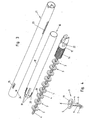
- FIG. 1 An embodiment of a device or a medical instrument according to the invention is in the Fig. 1 to 18 shown.
- the Fig. 1 and 2 show overall views of the device or the medical instrument, which could also be referred to as an applicator.
- Fig. 1 the medical instrument is shown assembled and in Fig. 2 is an end piece 1, which contains fastening anchors, which are provided for setting or application in human or animal tissue, shown decoupled from a control panel 2.
- the fastening anchor 3 also referred to as pin, used in this exemplary embodiment is shown in FIG Fig. 4 and comprises a shaft 4 to be pushed into the human tissue and at the end of the shaft 4, a part projecting outwards relative to the shaft 4, in particular a plate-shaped part, which serves to bear against the part to be fastened to the tissue by the fastening anchor 3, in particular a plastic net to be attached during an operation.
- the shaft 4 has barb-like projections 6, 7.
- the fastening anchor 3 further has a passing through this through-channel 8, with which it can be pushed onto a needle.
- an opening 9 is formed in the shell of the shaft 4, whereby the support of the fastening anchor 3 in the tissue is improved (since tissue can enter the opening 9).
- the fastening anchor 3 could also have a modified design with a differently designed plate-shaped outwardly projecting part or more of such outwardly projecting parts.
- the device comprises an actuating part 10, which between one in the Fig. 2 and 7 to 9 illustrated starting position and one in the 10 to 12 shown feed position is displaceable, in a feed direction 11 and against the same.
- the actuating part 10 is connected immovably to a needle holder 12 with respect to the feed direction.
- this connection between the actuating part 10 and the needle holder 12 is positively, for example in the form of a latching connection.
- the needle 13 is rigidly attached. During the displacement in and against the feed direction 11, the actuating part 10 thus takes the needle holder 12 and the needle 13 with.
- the needle 13 has at its front with respect to the feed direction 11 a tip. This can be formed as shown in the form of a piercing tip or in the form of a cutting tip.
- the central longitudinal axis of the device passes through the needle 13.
- the passage channels 8 are penetrated by the needle 13, wherein the individual on the needle 13 successively arranged fastening anchor 3 abut each other.
- the front end of the shaft 4 projects in each case over a short distance, which is shorter than 1/4 of the length of the entire fastening anchor, in an enlarged section of the Passage channel 8 at the rear end of the next front attachment anchor.
- a spring 14 which acts on this and thus also before this attachment anchor 3 in the feed direction 11.
- the spring formed in the embodiment shown in the form of a helical spring 14 is supported on the needle holder 12 at its rear end.
- the spring 14 is provided with a plurality of support discs 15 which are penetrated by the needle 13 through a bore.
- a sleeve-shaped in the embodiment shown Ein practiceil 16 in and against the feed direction 11 is fixed immovably.
- the push-in part 16 is rigidly connected to the needle holder 12 and thus also to the needle 13, for example by gluing to the needle holder 12.
- the sleeve-shaped indenting member 16 has a portion 17 which extends in the fully filled with mounting anchors 3 state of the device at least over some of the fastening anchors towards the front end of the needle 13 and at its front end attacking elements 18 to attack on the back side 19 of the projecting Part 5 of a mounting anchor 3 are arranged.
- the fastening anchor 3, on which the engagement elements 18 engage during the advance of the actuating part 10 is the foremost fastening anchor 3 arranged on the needle 13, which is preferred.
- the engagement elements 18 are tongue-shaped and are preferably formed by the front end of the sleeve-shaped indenting 16 outgoing, extending in the axial direction incisions are introduced. These tongues extend forward with respect to the feed direction 11, wherein they have an obliquely inward (ie in the direction of the needle 13) extending portion to abut with its front end on the plate-shaped, projecting part 5 of the fastening anchor 3.
- the tongue-shaped engagement elements 18 are resilient to the outside, ie in the direction of the needle 13 away deflected. Instead of an obliquely inwardly extending portion of these tongue-shaped engagement elements 18 could also be formed extending obliquely inwardly overall.
- the holding tongues 20 thus cooperate with the second frontmost fastening anchor 3 arranged on the needle 13.
- the retaining tongues 20 have at least one portion which extends obliquely forward and inward or run obliquely in total forward and inward.
- the indenting 16 is slidably disposed in an outer sleeve 21.
- the needle 13 and the needle holder 12 existing unit in the outer sleeve 21 12 opposite guide pins 22 are provided in the embodiment shown on the needle holder, which engage in extending in the longitudinal direction of the outer sleeve 21 guide slots 23.
- the outer sleeve 21 surrounds all arranged on the needle 13 mounting anchor.
- the outer sleeve 21 has opposite resilient retaining tongues 24, which in the starting position of the actuating member 10 with the projecting Part 5 of the foremost on the needle 13 arranged mounting anchor 3 cooperate and prevent its displacement in the feed direction 11.
- the retaining tongues 24 have at least one portion which extends obliquely forward and inward or extend obliquely forward and inward as a whole.
- the outer sleeve 21 opposite locking elements 25. Their front ends are located further back than the retaining tongues 24.
- the locking elements 25 are formed in the form of spring tongues, which extend forward and an obliquely inward, i. the needle 13 have approximate end portion. They could also be formed overall (over their entire length) obliquely forward and inward running.
- the actuating part 10 is, for example, via a latching mechanism with the needle holder 12 connected.
- the guide slots 23 constrictions. The force to guide the guide pins 22 through these constrictions is greater than the force required to lock the operating member 10 to the needle holder 12.
- the arranged at the front end of a transmission shaft 26 of the operating piece 2 operating part 10 can by means of a handle 27 of the operating piece 2, which is adjustable against the force of a spring, not shown in the figures in the feed direction 11 and the spring against the feed direction is reset, between its initial position and its feed position are moved.
- the actuating part 10 is displaced in the direction of advance, starting from its starting position, the needle 13 and the push-in part 16 are likewise displaced in the feed direction 11 with this.
- the engagement elements 18, which preferably act directly on the foremost fastening anchor 3 the foremost fastening anchor 3 located in its ready position in the area of the needle tip is guided past the retaining tongues 21, which are deflected outwards, and together with the front end portion of the needle 13 pushed out of the front end of the outer sleeve 21.
- the tip of the needle 13 in this case preferably runs somewhat forward of the front end of the shaft 4 (cf. Fig. 16 to 18 ).
- the outer sleeve 21 is placed in the setting process on the tissue into which the fastening anchor 3 is to be pressed, in this case the tissue from the tip of the needle 13 is pre-cut or pre-cut and the shaft 4 of the fastening anchor 3 pressed into the tissue.
- the retaining tongues 20 are provided for safety, so that the foremost fixing anchor 3 is not completely pushed out of the outer sleeve 21, if this during the Setting process is not always put on the fabric.
- the holding tongues 20 are so rigid that they can hold a fastening anchor 3 against the force of the spring 14. Due to the force of the spring 14, the fastening anchors 3 located behind the fastening anchor 3 acted upon by the engagement elements 18 move in the direction of advance, with the next-closest fastening anchor 3 being guided past the blocking elements 25.
- the fully advanced position of the needle 13 and the foremost fastening anchor 3 is reached, which has been pressed into its projection up to its projecting part 5, which is located at the front end of the outer sleeve 21.
- the retaining tongue 20 can be lifted from the projecting part 5 of the underlying behind the applied fastening anchor 3 mounting anchor 3, as is apparent from the 10 to 12 or 16 to 18 can be seen.
- the retaining tongues 24 then hold this fastening anchor 3 back against the force of the spring 14 and are designed to be correspondingly strong.
- the actuating member 10 is retracted against the feed direction 11, for example by acting on the handle 27 spring.
- the needle 13 is withdrawn from the passage 8 of the anchoring anchor 3 pressed into the tissue.
- a shift against the feed direction 11 is blocked when it comes to rest on the locking elements 25.
- the holding tongues 20 which are preferably provided are deflected outwards when the pressing-in part 16 is retracted and transferred over the projecting part 5 of the fastening anchor 3.
- the tongue-shaped engagement elements 18 are deflected outwards and transferred via the projecting part 5 of the fastening anchor 3.
- the actuating member 10 has again reached its initial position, the now foremost fastening anchor 3 has been moved on the needle 13 in the direction of the needle tip to the ready position for the next setting process.
- the other fastening anchors 3 are this nachgeschoben by the force of the spring 14 (see. Fig. 7 to 9 and 13 to 15 ).
- the spring 14 has compared to the in the Fig. 7 to 9 shown state after the setting process by the length of a fixing anchor 3 expands and a further such expansion takes place each time a fixing anchor.
- the free buckling length of the needle 13 would acquire a large value without the support plates 15.
- the free buckling length of the needle 13 is thereby reduced.
- the adjusting mechanism could also be formed without a spring 14.
- a claw member 28, as shown in the Fig. 19 is shown to be arranged on the needle 13.
- the claw part 28 has in at least one plane a plurality of spring tabs 30 projecting inwardly from an outer part.
- the opening 31 between these spring tabs 30 is slightly smaller than the diameter of the needle 13.
- several successively arranged planes or layers of such spring tabs 30 are present. like this in Fig. 19 is shown. If the claw part 28 is pushed axially from the side opposite the needle point on the needle 13, so the voltage applied to the needle 13 spring tabs 30 are bent to the back of the needle 13 out. As a result, the claw part 28 can be displaced in the direction of the tip of the needle 13 along this with little force, but a displacement in the opposite direction is blocked.
- This claw part 28 is arranged behind the rearmost fastening anchor 3 on the needle 13. Furthermore, a number of locking elements for the claw part 28 are provided in the outer sleeve 21, for example in the form of obliquely projecting in the feed direction inwardly projecting retaining tongues.
- the retaining tongues 20 and locking elements 25 can be omitted in this embodiment, while the retaining tongues 24 are preferably still present (but may be made weaker).
- the claw part 28 Upon advancement of the operating part 10 and with it the needle 13 and the indenting part 16, the claw part 28 is also advanced in the advancing direction 11, since a displacement of the claw part 28 with respect to the needle 13 in the direction of the rear end of the needle 13 is blocked.
- the claw part 28 thus displaces the fastening anchor 3 lying behind the fixing anchor 3 with which the engagement elements 18 of the push-in part 16 cooperate (preferably the foremost fastening anchor 3) also in the feed direction 11.
- the claw member 28 comes to a locking element of the outer sleeve 21 to the plant, so that its displacement against the feed direction 11 is blocked. It thereby shifts together with the remaining on the needle 13 mounting anchors 3 toward the tip of the needle. In this case, the engagement elements 18 of the press-in part 16 are transferred via the projecting part 5 of the next rear attachment anchor 3 in the provision of the pressing-16.
- the engagement elements 18 of the pressing-16 cooperate with the foremost on the needle 13 arranged fastening anchor 3. It would also be conceivable and possible, however, for the engagement elements 18 to interact with the second frontmost or even further fastening anchor 3 located further back. However, the portion 17 of the pressing member 16 extends, in the state of the device completely filled with fastening anchors 3, at least over some of the fastening anchors 3 towards the front end of the needle.
- this section in the form of two or more bolts, between which the fastening anchor 3 are.
- the operating piece 2 is reusable and serving as a magazine end piece 1 can be exchanged for exhaustion of the fastening anchor contained therein 3 against a new end piece 1, which is filled with mounting anchors 3 (this is the delivery state of the end pieces. 1 ).
- the device could also be designed as a disposable instrument.
- the operating piece 2 and end piece 1 could be integrally formed in this case, wherein the actuating member 10 may be formed integrally with the needle holder 12. In the delivery state, the disposable instrument is in turn completely filled with fastening anchors 3.
Abstract
Description
Die Erfindung betrifft eine zum Setzen von Befestigungsankern in das menschliche oder tierische Gewebe, insbesondere zur Befestigung von Kunststoffnetzen, mit einem Betätigungsteil, das für einen Setzvorgang von einer Ausgangsstellung zu einer Vorschubstellung in eine Vorschubrichtung vorschiebbar und entgegen der Vorschubrichtung zu seiner Ausgangsstellung rückstellbar ist, einer vom Betätigungsteil bei dessen Vorschub von der Ausgangsstellung zur Vorschubstellung vorgeschobenen und bei dessen Rückstellung von der Vorschubstellung zur Ausgangsstellung zurückgezogenen Nadel, die am bezogen auf die Vorschubrichtung vorderen Ende eine Nadelspitze besitzt, mehreren Befestigungsankern, die jeweils einen in das Gewebe einzudrückenden Schaft, mindestens einen gegenüber dem Schaft vorspringenden Teil mit einer dem vorderen Ende der Nadel abgewandten Rückseite und einen den Befestigungsanker durchsetzenden Durchgangskanal aufweisen und die auf der ihre Durchgangskanäle durchsetzenden Nadel angeordnet sind, einem beim Vorschub des Betätigungsteils von dessen Ausgangsstellung zur Vorschubstellung vorgeschobenen Eindrückteil zum Eindrücken des jeweils bezogen auf die Vorschubrichtung vordersten, in einer Bereitschaftsposition im Bereich der Nadelspitze sich befindenden Befestigungsankers ins Gewebe und einem Nachführmechanismus zum in Richtung zur Nadelspitze gerichteten Verschieben der hinter dem ins Gewebe einzudrückenden Befestigungsanker sich befindenden Befestigungsanker beim Setzvorgang.The invention relates to a set for fastening anchors in the human or animal tissue, in particular for the attachment of plastic nets, with an actuating member which is reset for a setting process from a starting position to a feed position in a feed direction and counter to the feed direction to its initial position, one advanced from the operating part at its feed from the starting position to the feed position and in its return from the feed position to the starting position retracted needle having a needle tip on relative to the feed direction front end, a plurality of mounting anchors, each one einzudrückenden in the tissue shaft, at least one opposite the shaft projecting portion having a rear end remote from the front end of the needle and a fastening channel passing through the passage channel and passing through the through channels Needle are arranged, one for advancing the operating part from its initial position to the feed position advanced Eindrückteil for pressing in each case with respect to the feed direction foremost, in a standby position in the needle point located fastening anchor into the tissue and a tracking mechanism directed towards the needle tip displacement of the behind the fixing anchor to be pressed into the tissue during the setting process.
Kunststoffnetze werden beispielsweise bei Bruchoperationen eingesetzt und müssen hierbei am menschlichen Gewebe befestigt werden. Außer Befestigungen durch Vernähen sind verschiedene Befestigungselemente bekannt geworden, beispielsweise Befestigungsanker, die einen in das menschliche Gewebe einzudrückenden Schaft und einen über den Schaft vorspringenden tellerförmigen Teil zur Halterung des Kunststoffnetzes aufweisen. Zum Setzen bzw. Eintreiben von solchen Befestigungsankern sind verschiedene Vorrichtungen bekannt geworden.Plastic nets are used, for example, in fracture operations and must be attached to human tissue. In addition to fastenings by sewing various fasteners have become known, for example fastening anchors, which have a shaft to be pressed into the human tissue and a protruding over the shaft plate-shaped part for holding the plastic net. For setting or driving of such mounting anchors various devices have become known.
Eine Vorrichtung der eingangs genannten Art ist aus der
Die
Eine weitere nicht gattungsgemäße Einrichtung ohne eine zentrale Führung für einen Befestigungsanker ist aus der
Aufgabe der Erfindung ist es, eine verbesserte Vorrichtung der eingangs genannten Art bereitzustellen, die eine relativ geringe Baulänge aufweist und auch für eine höhere Anzahl an Befestigungsankern ausgelegt werden kann. Erfindungsgemäß gelingt dies durch eine Vorrichtung mit den Merkmalen des Anspruchs 1.The object of the invention is to provide an improved device of the type mentioned, which has a relatively small length and can also be designed for a higher number of mounting anchors. According to the invention, this is achieved by a device having the features of claim 1.
Gemäß der Erfindung greift das Eindrückteil somit nicht am letzten auf der Nadel angeordneten Befestigungsanker, sondern an einem weiter vorne liegenden, vorzugsweise am vordersten, der auf der Nadel angeordneten Befestigungsanker an. Bei der Rückstellung des Betätigungsteils nach dem Setzen des vordersten Befestigungsankers werden die Anlageelemente des Eingriffsteils mit dem nächsthinteren auf der Nadel angeordneten Befestigungsanker in Eingriff gebracht und greifen somit beim nächsten Setzvorgang an diesem an. Die Funktion des Nachstellmechanismus kann hierbei von der Anzahl der hinter dem Befestigungsanker, an welchem das Eindrückteil angreift, liegenden Befestigungsanker unabhängig sein, so dass sich die Vorrichtung auch für eine größere Anzahl von auf der Nadel angeordneten Befestigungsankern eignet. Weiters wird durch die erfindungsgemäße Ausbildung, bei der das Eindrückteil bei jedem Setzvorgang mit dem nächsthinteren, auf der Nadel in Richtung zu deren Spitze nachrückenden Befestigungsanker in Eingriff gebracht wird, eine relativ kurze Baulänge der Vorrichtung ermöglicht.According to the invention, the push-in part thus does not engage with the last fastening anchor arranged on the needle, but with a fastening anchor located further forward, preferably at the front, of the needle. Upon return of the operating part after setting the foremost fixing anchor, the abutment elements of the engaging part are brought into engagement with the next-closest fastening anchor arranged on the needle and thus engage in the next setting process on this. The function of the adjusting mechanism may be independent of the number of fastening anchors behind the fastening anchor on which the pressing-in part engages, so that the device is also suitable for a larger number of fastening anchors arranged on the needle. Furthermore, a relatively short length of the device is made possible by the inventive construction in which the indenting is brought into each setting process with the next rear, on the needle in the direction of the tip nachrückenden fastening anchor engaged.
Erfindungsgemäß kann weiters eine sehr direkte Kraftübertragung auf den zu setzenden Befestigungsanker erreicht werden, die das Setzen erleichtert.According to the invention, furthermore, a very direct transmission of force to the fastening anchor to be set can be achieved, which facilitates setting.
In einer vorteilhaften Ausführungsform der Erfindung umfasst der Nachführmechanismus eine am hintersten auf der Nadel angeordneten Befestigungsanker angreifende Feder, welche diesen Befestigungsanker in die Vorschubrichtung beaufschlagt. Das Eindrückteil weist hierbei bevorzugterweise mindestens eine federelastische Haltezunge auf, welche in der Ausgangsstellung des Betätigungsteils mit mindestens einem vorspringenden Teil desjenigen Befestigungsankers zusammenwirkt, der dem Befestigungsanker nachfolgt, an dem die Angriffselemente des Eindrückteils angreifen. Die mindestens eine federelastische Haltezunge kann diesen nachfolgenden Befestigungsanker gegen die Federkraft der Feder des Nachführmechanismus zurückhalten.In an advantageous embodiment of the invention, the tracking mechanism comprises a spring which acts on the needle at the rearmost point and acts on this fastening anchor in the feed direction. In this case, the push-in part preferably has at least one spring-elastic retaining tongue which, in the initial position of the actuating part, cooperates with at least one projecting part of the fastening anchor which follows the fastening anchor against which the engagement elements of the push-in part engage. The at least one resilient retaining tongue can retain this subsequent fastening anchor against the spring force of the spring of the tracking mechanism.
Vorzugsweise ist das Eindrückteil hülsenförmig ausgebildet und die federelastischen Haltezungen erstrecken sich schräg nach innen und vorne (bezogen auf die Vorschubrichtung).Preferably, the indenting part is sleeve-shaped and the resilient retaining tongues extend obliquely inward and forward (relative to the feed direction).
Eine vorteilhafte Ausführungsform der Erfindung sieht vor, dass das Eindrückteil verschiebbar in einer Außenhülse angeordnet ist, welche mindestens eine federelastische Haltezunge aufweist, die in der Ausgangsstellung des Betätigungsteils mit mindestens einem vorspringenden Teil des vordersten auf der Nadel angeordneten Befestigungsankers zusammenwirkt, um diesen gegen eine Verschiebung in die Vorschubrichtung zurückzuhalten.An advantageous embodiment of the invention provides that the indenting is slidably disposed in an outer sleeve having at least one resilient retaining tongue which cooperates in the initial position of the actuating part with at least one projecting part of the frontmost on the needle mounting anchor, to this against displacement to restrain in the feed direction.
Vorzugsweise besitzt die Außenhülse weiters mindestens ein Sperrelement, von dem bei der Rückstellung des Betätigungselements von seiner Vorschubstellung zu seiner Ausgangsstellung eine Verschiebung des nächsthinteren Befestigungsankers entgegen der Vorschubrichtung blockiert wird, wobei eine Überführung der Angriffselemente des Eindrückteils über oder um mindestens eine vorspringenden Teil des nächsthinteren Befestigungsankers erfolgt. Durch die Blockierung des Befestigungsankers bei der Rückstellung des Betätigungsteils erfolgt weiters eine Überführung der mindestens einen federelastischen Haltezunge des Eindrückteils über oder um den mindestens einen vorspringenden Teil des Befestigungsankers.Preferably, the outer sleeve further has at least one blocking element, is blocked by the return of the actuating element from its feed position to its initial position, a displacement of the next rear mounting anchor against the feed direction, wherein a transfer of the engagement elements of the indenting over or around at least one projecting part of the next rear attachment anchor he follows. By blocking the fastening anchor in the provision of the operating part further carried over a transfer of the at least one resilient retaining tongue of the pressing over or around the at least one projecting part of the fastening anchor.
Wenn in dieser Schrift von "vorne" und "hinten" die Rede ist, so ist dies auf die Vorschubrichtung des Betätigungsteils bzw. auf die Richtung bezogen, in welche der Befestigungsanker gesetzt wird. Die Angaben "außen" und "innen" sind auf die zentrale Längsachse der Vorrichtung bezogen, d.h. ein weiter außen liegendes Teil besitzt einen größeren Abstand von der zentralen Längsachse als ein weiter innen liegendes Teil.If this document is referred to as "front" and "rear", this is based on the feed direction of the actuating part or on the direction in which the fastening anchor is set. The terms "outside" and "inside" refer to the central longitudinal axis of the device, i. a further outward portion has a greater distance from the central longitudinal axis than a further inward portion.
Weitere Vorteile und Einzelheiten der Erfindung werden im Folgenden anhand der beiliegenden Zeichnung erläutert. In dieser zeigen:
- Fig. 1
- eine Schrägsicht eines Ausführungsbeispiels einer erfindungsgemäßen Vorrichtung;
- Fig. 2
- die Vorrichtung im abgenommenen Zustand eines vorderen Endstücks;
- Fig. 3
- das Endstück im auseinandergezogen dargestellten Zustand von Teilen desselben, in Schrägsicht;
- Fig. 4
- einen Befestigungsanker in Schrägsicht;
- Fig. 5
- eine Seitenansicht der auf der Nadel anzuordnenden Feder;
- Fig. 6
- eine Schrägsicht der Nadel und des Nadelhalters;
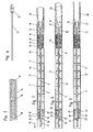
- Fig. 7 bis Fig. 9
- Längsschnitte durch das Endstück in der Ausgangsstellung des Betätigungsteils, wobei die Schnittebene jeweils um 120° gedreht ist;
- Fig. 10 bis Fig. 12
- Längsschnitte entsprechend den
Fig. 7 bis 9 , aber in der Vorschubstellung des Betätigungsteils; - Fig. 13 bis Fig. 15
- vergrößerte Ausschnitte der
Fig. 7 bis 9 ; - Fig. 16 bis Fig. 18
- vergrößerte Ausschnitte der
Fig. 10 bis 12 ; - Fig. 19
- ein Krallteil eines Nachstellmechanismus gemäß einer weiteren Ausführungsform der Erfindung.
- Fig. 1
- an oblique view of an embodiment of a device according to the invention;
- Fig. 2
- the device in the detached state of a front end piece;
- Fig. 3
- the tail in the exploded state of parts thereof, in oblique view;
- Fig. 4
- a fastening anchor in oblique view;
- Fig. 5
- a side view of the needle to be arranged on the spring;
- Fig. 6
- an oblique view of the needle and the needle holder;
- FIGS. 7 to 9
- Longitudinal sections through the tail in the starting position of the operating part, wherein the cutting plane is rotated in each case by 120 °;
- 10 to FIG. 12
- Longitudinal sections corresponding to
Fig. 7 to 9 but in the advancing position of the operating part; - FIGS. 13 to 15
- enlarged sections of the
Fig. 7 to 9 ; - FIGS. 16 to 18
- enlarged sections of the
10 to 12 ; - Fig. 19
- a claw part of an adjusting mechanism according to another embodiment of the invention.
Ein Ausführungsbeispiel einer Vorrichtung bzw. eines medizinischen Instruments gemäß der Erfindung ist in den
Der bei diesem Ausführungsbeispiel verwendete Befestigungsanker 3, auch Pin genannt, ist in
Die Vorrichtung umfasst ein Betätigungsteil 10, welches zwischen einer in den
Die Nadel 13 besitzt an ihrem bezogen auf die Vorschubrichtung 11 vorderen Ende eine Spitze. Diese kann wie gezeigt in Form einer Stechspitze oder auch in Form einer Schneidspitze ausgebildet sein. Die zentrale Längsachse der Vorrichtung läuft durch die Nadel 13.The
Auf der Nadel 13 sind eine Mehrzahl von Befestigungsankern 3 angeordnet, deren Durchgangskanäle 8 von der Nadel 13 durchsetzt werden, wobei die einzelnen auf der Nadel 13 hintereinander angeordneten Befestigungsanker 3 aneinander anliegen. Die Durchgangskanäle 8 der auf der Nadel 13 angeordneten Befestigungsanker 3 liegen somit parallel zur Nadel 13. Im gezeigten Ausführungsbeispiel ragt das vordere Ende des Schaftes 4 jeweils über ein kurzes Stück, welches kürzer als ¼ der Länge des gesamten Befestigungsankers ist, in einen vergrößerten Abschnitt des Durchgangskanals 8 am hinteren Ende des nächstvorderen Befestigungsankers 3.On the
Am hintersten Befestigungsanker 3 greift eine Feder 14 an, welche diesen und somit auch vor diesem liegende Befestigungsanker 3 in die Vorschubrichtung 11 beaufschlagt. Die im gezeigten Ausführungsbeispiel in Form einer Schraubenfeder 14 ausgebildete Feder stützt sich an ihrem hinteren Ende am Nadelhalter 12 ab.At the
Die Feder 14 ist mit mehreren Stützscheiben 15 versehen, die von der Nadel 13 durch eine Bohrung durchsetzt werden.The
Am Nadelhalter 12 ist ein im gezeigten Ausführungsbeispiel hülsenförmig ausgebildetes Eindrückteil 16 in und entgegen der Vorschubrichtung 11 unverschiebbar festgelegt. Vorzugsweise ist das Eindrückteil 16 mit dem Nadelhalter 12 und somit auch mit der Nadel 13 starr verbunden, beispielsweise durch Verklebung mit dem Nadelhalter 12.At the
Das hülsenförmige Eindrückteil 16 weist einen Abschnitt 17 auf, der sich im vollständig mit Befestigungsankern 3 gefüllten Zustand der Vorrichtung zumindest über einige der Befestigungsanker in Richtung zum vorderen Ende der Nadel 13 erstreckt und an dessen vorderem Ende Angriffselemente 18 zum Angriff an der Rückseite 19 des vorspringenden Teils 5 eines Befestigungsankers 3 angeordnet sind. Im gezeigten Ausführungsbeispiel ist der Befestigungsanker 3, an dem die Angriffselemente 18 beim Vorschub des Betätigungsteils 10 angreifen, der vorderste auf der Nadel 13 angeordnete Befestigungsanker 3, was bevorzugt ist.The sleeve-shaped indenting
Die Angriffselemente 18 sind zungenförmig und werden bevorzugterweise gebildet, indem vom vorderen Ende des hülsenförmigen Eindrückteils 16 ausgehende, in achsialer Richtung verlaufende Einschnitte eingebracht werden. Diese Zungen erstrecken sich bezogen auf die Vorschubrichtung 11 nach vorne, wobei sie einen schräg nach innen (also in Richtung zur Nadel 13) verlaufenden Abschnitt aufweisen, um mit ihrem vorderen Ende am tellerförmigen, vorspringenden Teil 5 des Befestigungsankers 3 anzuliegen. Die zungenförmigen Angriffselemente 18 sind federelastisch nach außen, also in Richtung von der Nadel 13 weg auslenkbar. Anstelle eines schräg nach innen verlaufenden Abschnitts könnten diese zungenförmigen Angriffselemente 18 auch insgesamt schräg nach innen verlaufend ausgebildet sein.The
Im Bereich des vorderen Endes des Eindrückteils 16 besitzt dieses weiters zwei gegenüberliegende federelastische Haltezungen 20. Diese wirken mit dem vorspringenden Teil 5 desjenigen Befestigungsankers 3 zusammen, der dem Befestigungsanker 3 nachfolgt, an dem die Angriffselemente 18 des Eindrückteils 16 angreifen. Im gezeigten Ausführungsbeispiel wirken die Haltezungen 20 also mit dem zweitvordersten auf der Nadel 13 angeordneten Befestigungsanker 3 zusammen. Die Haltezungen 20 weisen zumindest einen Abschnitt auf, der schräg nach vorne und innen verläuft oder verlaufen insgesamt schräg nach vorne und innen.In the region of the front end of the pressing-16 this further has two opposing resilient retaining
Das Eindrückteil 16 ist verschiebbar in einer Außenhülse 21 angeordnet. Zur verschiebbaren Lagerung der aus dem Eindrückteil 16, der Nadel 13 und dem Nadelhalter 12 bestehenden Einheit in der Außenhülse 21 sind im gezeigten Ausführungsbeispiel am Nadelhalter 12 gegenüberliegende Führungszapfen 22 vorgesehen, die in in Längsrichtung der Außenhülse 21 verlaufende Führungsschlitze 23 eingreifen.The indenting 16 is slidably disposed in an
In der Ausgangsstellung des Betätigungsteils 10 umgibt die Außenhülse 21 alle auf der Nadel 13 angeordnete Befestigungsanker 3.In the initial position of the
In ihrem vorderen Endbereich besitzt die Außenhülse 21 gegenüberliegende federelastische Haltezungen 24, die in der Ausgangsstellung des Betätigungsteils 10 mit dem vorspringenden Teil 5 des vordersten auf der Nadel 13 angeordneten Befestigungsankers 3 zusammenwirken und dessen Verschiebung in die Vorschubrichtung 11 verhindern. Die Haltezungen 24 weisen zumindest einen Abschnitt auf, der sich schräg nach vorne und innen erstreckt oder strecken sich insgesamt schräg nach vorne und innen.In its front end portion, the
Weiters weist die Außenhülse 21 gegenüberliegende Sperrelemente 25 auf. Deren vordere Enden befinden sich weiter hinten als die Haltezungen 24. Im gezeigten Ausführungsbeispiel sind die Sperrelemente 25 in Form von Federzungen ausgebildet, die sich nach vorne erstrecken und einen schräg nach innen, d.h. der Nadel 13 sich annähernden Endabschnitt aufweisen. Sie könnten auch insgesamt (über ihre gesamte Länge) schräg nach vorne und innen verlaufend ausgebildet sein.Furthermore, the
Bei der gezeigten Ausführungsform, bei der das vordere Endstück 1 an- und abkoppelbar mit dem Bedienstück 2 verbunden ist, um eine Auswechslung des vorderen Endstücks 1 nach dem Aufbrauch der Befestigungsanker 3 zu ermöglichen, ist das Betätigungsteil 10 beispielsweise über einen Rastmechanismus mit dem Nadelhalter 12 verbunden. Damit sich beim Aufstecken des Endstücks 1 auf das Bedienstück 2, bei welchem die Verrastung des Nadelhalters 12 mit dem Betätigungsteil 10 erfolgt, die Nadel 13 und das Eindrückteil 16 nicht nach vorne verschieben, weisen die Führungsschlitze 23 Verengungen auf. Die Kraft, um die Führungszapfen 22 durch diese Verengungen zu führen, ist größer als die zum Verrasten des Betätigungsteils 10 mit dem Nadelhalter 12 erforderliche Kraft.In the embodiment shown, in which the front end piece 1 is connected to and detachable from the
Das am vorderen Ende eines Übertragungsschafts 26 des Bedienstücks 2 angeordnete Betätigungsteil 10 kann mittels einer Handhabe 27 des Bedienstücks 2, die gegen die Kraft einer in den Figuren nicht dargestellten Feder in die Vorschubrichtung 11 verstellbar ist und von der Feder entgegen der Vorschubrichtung rückstellbar ist, zwischen seiner Ausgangsstellung und seiner Vorschubstellung verschoben werden.The arranged at the front end of a
Wird zum Setzen eines Befestigungsankers 3 das Betätigungsteil 10 ausgehend von seiner Ausgangsstellung in die Vorschubrichtung verschoben, so werden mit diesem die Nadel 13 und das Eindrückteil 16 ebenfalls in die Vorschubrichtung 11 verschoben. Mittels der Eingriffselemente 18, die vorzugsweise direkt am vordersten Befestigungsanker 3 angreifen, wird der sich in seiner Bereitschaftsposition im Bereich der Nadelspitze befindende vorderste Befestigungsanker 3 an den Haltezungen 21 vorbeigeführt, wobei diese nach außen ausgelenkt werden, und zusammen mit dem vorderen Endabschnitt der Nadel 13 aus dem vorderen Ende der Außenhülse 21 hinausgeschoben. Die Spitze der Nadel 13 läuft hierbei dem vorderen Ende des Schafts 4 bevorzugterweise etwas vor (vgl.
Die Haltezungen 20 sind zur Sicherheit vorgesehen, damit der vorderste Befestigungsanker 3 nicht gleich vollständig aus der Außenhülse 21 herausgedrückt wird, wenn diese während des Setzvorgangs nicht immer auf das Gewebe aufgesetzt ist. Die Haltezungen 20 sind hierfür so starr, dass sie einen Befestigungsanker 3 gegen die Kraft der Feder 14 halten können. Durch die Kraft der Feder 14 rücken die hinter dem von den Angriffselementen 18 beaufschlagten Befestigungsanker 3 liegenden Befestigungsanker 3 in die Vorschubrichtung nach, wobei der nächsthintere Befestigungsanker 3 unter Auslenkung der Sperrelemente 25 an diesen vorbeigeführt wird.The retaining
In der Vorschubstellung des Betätigungsteils 10 ist die vollständig vorgeschobene Stellung der Nadel 13 und des vordersten Befestigungsankers 3 erreicht, der bis zu seinem vorspringenden Teil 5, welches sich am vorderen Ende der Außenhülse 21 befindet, in das Gewebe eingedrückt worden ist. In dieser vollständig vorgeschobenen Stellung kann die Haltezunge 20 vom vorspringenden Teil 5 des hinter dem beaufschlagten Befestigungsanker 3 liegenden Befestigungsankers 3 abgehoben sein, wie dies aus den
Nachdem die vollständig vorgeschobene Stellung der Nadel 13 und des vordersten Befestigungsankers 3 erreicht ist, wobei sich das Betätigungsteil 10 in seiner Vorschubstellung befindet (vgl.
Weiters werden beim Zurückziehen des Eindrückteils 16 die zungenförmigen Angriffselemente 18 nach außen ausgelenkt und über den vorspringenden Teil 5 des Befestigungsankers 3 überführt. Wenn das Betätigungsteil 10 wiederum seine Ausgangsstellung erreicht hat, so ist der nunmehr vorderste Befestigungsanker 3 auf der Nadel 13 in Richtung zur Nadelspitze bis zur Bereitschaftsposition für den nächsten Setzvorgang verschoben worden. Die anderen Befestigungsanker 3 sind diesem durch die Kraft der Feder 14 nachgeschoben worden (vgl.
Die Feder 14 hat sich gegenüber dem in den
Bei zunehmender Expansion der Feder 14 würde ohne die Stützscheiben 15 die freie Knicklänge der Nadel 13 einen großen Wert erlangen. Durch die Stützscheiben 15, insbesondere die mindestens eine im Bereich der Mitte der Nadel angeordnete Stützscheibe 15 wird die Nadel 13 bei diesen Stützscheiben abgestützt, welche ihrerseits von der Außenhülse 21 abgestützt sind. Die freie Knicklänge der Nadel 13 wird dadurch verringert.With increasing expansion of the
Der Nachstellmechanismus könnte auch ohne eine Feder 14 ausgebildet sein. Zu diesem Zweck könnte beispielsweise ein Krallteil 28, wie es in der
Dieses Krallteil 28 wird hinter dem hintersten Befestigungsanker 3 auf der Nadel 13 angeordnet. Weiters werden in der Außenhülse 21 eine Reihe von Sperrelementen für das Krallteil 28 vorgesehen, beispielsweise in Form von schräg in der Vorschubrichtung nach innen abstehenden Haltezungen. Die Haltezungen 20 und Sperrelemente 25 können in diesem Ausführungsbeispiel entfallen, während die Haltezungen 24 vorzugsweise nach wie vor vorhanden sind (aber schwächer ausgebildet sein können).This
Bei einem Vorschub des Betätigungsteils 10 und mit ihm der Nadel 13 und des Eindrückteils 16 wird das Krallteil 28 ebenfalls in die Vorschubrichtung 11 vorgeschoben, da eine Verschiebung des Krallteils 28 gegenüber der Nadel 13 in Richtung zum hinteren Ende der Nadel 13 blockiert ist. Das Krallteil 28 verschiebt somit die hinter demjenigen Befestigungsanker 3, mit dem die Angriffselemente 18 des Eindrückteils 16 zusammenwirken (vorzugsweise dem vordersten Befestigungsanker 3), liegenden Befestigungsanker 3 ebenfalls in die Vorschubrichtung 11.Upon advancement of the operating
Bei einer Rückstellung des Betätigungsteils 10 und mit ihm der Nadel 13 und des Eindrückteils 16 entgegen der Vorschubrichtung 11 kommt das Krallteil 28 an einem Sperrelement der Außenhülse 21 zur Anlage, so dass dessen Verschiebung entgegen der Vorschubrichtung 11 blockiert ist. Es verschiebt sich dadurch zusammen mit den auf der Nadel 13 verbliebenen Befestigungsankern 3 in Richtung zur Spitze der Nadel. Hierbei werden bei der Rückstellung des Eindrückteils 16 die Angriffselemente 18 des Eindrückteils 16 über den vorspringenden Teil 5 des nächsthinteren Befestigungsankers 3 überführt.Upon a return of the
Unterschiedliche Modifikationen der gezeigten Ausführungsbeispiele sind denkbar und möglich, ohne den Bereich der Erfindung zu verlassen. So wäre es prinzipiell beispielsweise denkbar und möglich, anstelle eines umfänglich vorspringenden Teils 5 einen jeweiligen Befestigungsanker 3 mit zwei oder mehr einzelnen, um den Umfang verteilten vorspringenden Teilen zu versehen. Die Angriffselemente 18 des Eindrückteils 16 könnten in diesem Fall bei der Rückstellung des Betätigungsteils 10 auch in Umfangsrichtung auslenkbar ausgebildet sein und somit um die vorspringenden Teile 5 des betreffenden Befestigungsankers 3 überführt werden.Various modifications of the embodiments shown are conceivable and possible without departing from the scope of the invention. So it would be possible in principle, for example and it is possible to provide, instead of a peripheral
Zwar ist es bevorzugt, dass die Angriffselemente 18 des Eindrückteils 16 mit dem vordersten auf der Nadel 13 angeordneten Befestigungsanker 3 zusammenwirken. Denkbar und möglich wäre es aber auch, dass die Angriffselemente 18 mit dem zweitvordersten oder einem noch weiter hinten liegenden Befestigungsanker 3 zusammenwirken. Der Abschnitt 17 des Eindrückteils 16 erstreckt sich aber, im mit Befestigungsankern 3 vollständig befüllten Zustand der Vorrichtung, zumindest über einige der Befestigungsanker 3 in Richtung zum vorderen Ende der Nadel.Although it is preferred that the
Anstelle einer hülsenförmigen Ausbildung des Abschnitts 17 des Eindrückteils 16, an dessen vorderem Ende die Angriffselemente 18 angeordnet sind, wäre es beispielsweise auch denkbar und möglich, diesen Abschnitt in Form von zwei oder mehreren Bolzen auszubilden, zwischen denen die Befestigungsanker 3 liegen.Instead of a sleeve-shaped design of the portion 17 of the
Bei dem in den Figuren dargestellten Ausführungsbeispiel ist das Bedienstück 2 mehrfach verwendbar und das als Magazin dienende Endstück 1 kann nach Aufbrauch der darin enthaltenen Befestigungsanker 3 gegen ein neues Endstück 1 ausgetauscht werden, welches mit Befestigungsankern 3 befüllt ist (dies ist der Auslieferungszustand der Endstücke 1). Stattdessen könnte die Vorrichtung auch als Einweginstrument ausgebildet sein. Das Bedienstück 2 und Endstück 1 könnten in diesem Falle einstückig ausgebildet sein, wobei das Betätigungsteil 10 mit dem Nadelhalter 12 einstückig ausgebildet sein könnte. Im Auslieferungszustand ist das Einweginstrument wiederum mit Befestigungsankern 3 vollständig befüllt.In the embodiment shown in the figures, the
- 11
- Endstücktail
- 22
- Bedienstückoperating piece
- 33
- Befestigungsankerfastening anchor
- 44
- Schaftshaft
- 55
- vorspringender Teilprojecting part
- 66
- Vorsprunghead Start
- 77
- Vorsprunghead Start
- 88th
- DurchgangskanalThrough channel
- 99
- Öffnungopening
- 1010
- Betätigungsteilactuating member
- 1111
- Vorschubrichtungfeed direction
- 1212
- Nadelhalterneedle holder
- 1313
- Nadelneedle
- 1414
- Federfeather
- 1515
- Stützscheibesupport disc
- 1616
- EindrückteilEindrückteil
- 1717
- Abschnittsection
- 1818
- Angriffselementengaging member
- 1919
- Rückseiteback
- 2020
- Haltezungeholding tongue
- 2121
- Außenhülseouter sleeve
- 2222
- Führungszapfenspigot
- 2323
- Führungsschlitzguide slot
- 2424
- Haltezungeholding tongue
- 2525
- Sperrelementblocking element
- 2626
- Übertragungsschafttransmission shaft
- 2727
- Handhabehandle
- 2828
- KrallteilKrall part
- 2929
- Außenteilouter part
- 3030
- Federlappenspring tabs
- 3131
- Öffnungopening
Claims (13)
- A device for the placing of securing anchors into human or animal tissue, in particular for the securing of plastics meshes, having an actuating part (10) which for a placing procedure can be advanced from an initial position to a feed position in a feed direction (11) and can be restored contrary to the feed direction (11) to its initial position, a needle (13) which is advanced by the actuating part (10) upon advancing of the latter from the initial position to the feed position and is retracted upon restoration of the actuating part (10) from the feed position to the initial position and which has a needle point at the front end related to the feed direction (11), a plurality of securing anchors which each have a shaft (4), to be pushed into the tissue, at least one part (5), projecting with respect to the shaft (4) and having a rear side remote from the front end of the needle (13), and a through channel (8), passing through the securing anchor (3), and which are arranged on the needle (13) passing through their through channels (8), a pushing part (16), advanced upon advancing of the actuating part (10) from its initial position to the feed position, to push the securing anchor (3), foremost in each case related to the feed direction and located in a ready position in the region of the needle point, into the tissue, and a movement-following mechanism for the displacement, directed in the direction of the needle point, during the placement procedure of the securing anchors (3) located behind the securing anchor to be pushed into the tissue, characterised in that the pushing part (16) has a portion (17) which, when the device is in the state in which it is completely filled with securing anchors (3), extends over a plurality of the securing anchors (3), in the direction of the front end of the needle (13), and at the front end of which there are arranged contact elements (18) to contact the rear side of at least one projecting part (5) of a securing anchor (3), and in that upon restoration of the actuating part (10) from its feed position to its initial position, the contact elements (18) of the pushing part (16) can be conveyed over or around at least one projecting part (5) of the next-behind securing anchor (3) and can be brought into contact with the rear side of at least one projecting part (5) of this next-behind securing anchor (3).
- A device according to claim 1, characterised in that the portion (17), at the front end of which the contact elements (18) are arranged, of the pushing part (16) is sleeve-shaped.
- A device according to claim 1 or claim 2, characterised in that the pushing part (16) and the needle (13) are nondisplaceably connected to one another in and contrary to the feed direction (11).
- A device according to any one of claims 1 to 3, characterised in that the contact elements (18) are in the form of tongues which are resiliently deflectable for conveying over or around the at least one projecting part (5) of the next-behind securing anchor (3).
- A device according to any one of claims 1 to 4, characterised in that the contact elements (18) of the pushing part (16) contact the securing anchor (3) located foremost on the needle (13) in each case.
- A device according to any one of claims 1 to 5, characterised in that the pushing part (16) is displaceably arranged in an outer sleeve (21).
- A device according to claim 6, characterised in that at least in the initial position of the actuating part (10), the outer sleeve (21) surrounds all securing anchors (3) arranged on the needle (13).
- A device according to claim 6 or claim 7, characterised in that the outer sleeve (21) has at last one resilient holding tongue (24) which, in the initial position of the actuating part (10), cooperates with at least one projecting part (5) of the foremost securing anchor (3), in order to restrain the foremost securing anchor (3) against displacement in the feed direction (11).
- A device according to any one of claims 1 to 8, characterised in that the movement-following mechanism has a spring (14) which contacts the last securing anchor (3) related to the advance direction (11) and which acts thereupon in the feed direction (11).
- A device according to claim 9, characterised in that the spring (14) has at least one supporting disc (15) arranged in a middle region of the spring (14), the needle (13) passing through the supporting disc (15) through a bore.
- A device according to claim 9 or claim 10, characterised in that the pushing part (16) has at least one resilient holding tongue (20) which, in the initial position of the actuating part (10), cooperates with at least one projecting part (5) of that securing anchor (3) which comes after the securing anchor (3) on which the contact elements (18) of the pushing part (16) contact, in order to restrain this securing anchor (3) against displacement taking place in the feed direction (11) by the spring (14).
- A device according to any one of claims 6 to 11, characterised in that the outer sleeve (21) has at least one locking elements (25) by which, upon restoration of the actuating part (10) from its feed position to its initial position, displacement of the next-behind securing anchor (3) contrary to the feed direction (11) is blocked, wherein conveying of the contact elements (18) of the pushing part (16) over or around at least one projecting part (5) of the next-behind securing anchor (3) takes place.
- A device according to claim 12, characterised in that through the blocking of the securing anchor (3), upon restoration of the actuating part (10) there also takes place a conveying of the at least one resilient holding tongue (20) of the pushing part (16), accompanied by resilient deflection thereof, over or around the at least one projecting part of the securing anchor (3).
Applications Claiming Priority (2)
| Application Number | Priority Date | Filing Date | Title |
|---|---|---|---|
| AT3332006 | 2006-02-28 | ||
| PCT/AT2007/000078 WO2007098512A1 (en) | 2006-02-28 | 2007-02-14 | Device for inserting securing anchors into human or animal tissue |
Publications (2)
| Publication Number | Publication Date |
|---|---|
| EP2012677A1 EP2012677A1 (en) | 2009-01-14 |
| EP2012677B1 true EP2012677B1 (en) | 2011-11-16 |
Family
ID=38110394
Family Applications (1)
| Application Number | Title | Priority Date | Filing Date |
|---|---|---|---|
| EP07701322A Active EP2012677B1 (en) | 2006-02-28 | 2007-02-14 | Device for inserting securing anchors into human or animal tissue |
Country Status (4)
| Country | Link |
|---|---|
| EP (1) | EP2012677B1 (en) |
| AT (1) | ATE533410T1 (en) |
| ES (1) | ES2377011T3 (en) |
| WO (1) | WO2007098512A1 (en) |
Cited By (2)
| Publication number | Priority date | Publication date | Assignee | Title |
|---|---|---|---|---|
| US10251642B2 (en) | 2013-03-14 | 2019-04-09 | C.R. Bard, Inc. | Handling of fasteners within a surgical instrument |
| US10327775B2 (en) | 2013-03-14 | 2019-06-25 | C.R. Bard, Inc. | Handling of fasteners within a surgical instrument |
Families Citing this family (20)
| Publication number | Priority date | Publication date | Assignee | Title |
|---|---|---|---|---|
| US8911494B2 (en) | 2009-05-04 | 2014-12-16 | Valtech Cardio, Ltd. | Deployment techniques for annuloplasty ring |
| US8715342B2 (en) * | 2009-05-07 | 2014-05-06 | Valtech Cardio, Ltd. | Annuloplasty ring with intra-ring anchoring |
| US10517719B2 (en) | 2008-12-22 | 2019-12-31 | Valtech Cardio, Ltd. | Implantation of repair devices in the heart |
| DE102009054005A1 (en) * | 2009-11-19 | 2011-05-26 | A. Raymond Et Cie | Fixing anchor, fixing anchor band and setting tool |
| FR2977471B1 (en) | 2011-07-07 | 2013-07-05 | Aspide Medical | DEVICE COMPRISING A PLURALITY OF IMPLANTS FOR FIXING PROTHETIC EQUIPMENT |
| EP2775896B1 (en) | 2011-11-08 | 2020-01-01 | Valtech Cardio, Ltd. | Controlled steering functionality for implant-delivery tool |
| WO2014064694A2 (en) | 2012-10-23 | 2014-05-01 | Valtech Cardio, Ltd. | Controlled steering functionality for implant-delivery tool |
| US9724084B2 (en) | 2013-02-26 | 2017-08-08 | Mitralign, Inc. | Devices and methods for percutaneous tricuspid valve repair |
| CN105283214B (en) | 2013-03-15 | 2018-10-16 | 北京泰德制药股份有限公司 | Translate conduit, system and its application method |
| US10070857B2 (en) | 2013-08-31 | 2018-09-11 | Mitralign, Inc. | Devices and methods for locating and implanting tissue anchors at mitral valve commissure |
| US10299793B2 (en) | 2013-10-23 | 2019-05-28 | Valtech Cardio, Ltd. | Anchor magazine |
| US10285697B2 (en) * | 2013-11-08 | 2019-05-14 | C.R. Bard, Inc. | Methods and apparatus for surgical fastening |
| EP3397207A4 (en) | 2015-12-30 | 2019-09-11 | Mitralign, Inc. | System and method for reducing tricuspid regurgitation |
| JP6965249B2 (en) * | 2016-01-13 | 2021-11-10 | シャープ フリューディクス エルエルシー | Fixed device delivery system |
| US11045627B2 (en) | 2017-04-18 | 2021-06-29 | Edwards Lifesciences Corporation | Catheter system with linear actuation control mechanism |
| US10835221B2 (en) | 2017-11-02 | 2020-11-17 | Valtech Cardio, Ltd. | Implant-cinching devices and systems |
| US10932776B2 (en) | 2018-01-10 | 2021-03-02 | C.R. Bard, Inc. | Surgical fasteners for articulating surgical instruments |
| EP3743015A1 (en) | 2018-01-24 | 2020-12-02 | Valtech Cardio, Ltd. | Contraction of an annuloplasty structure |
| WO2020012481A2 (en) | 2018-07-12 | 2020-01-16 | Valtech Cardio, Ltd. | Annuloplasty systems and locking tools therefor |
| EP4051182A1 (en) | 2019-10-29 | 2022-09-07 | Edwards Lifesciences Innovation (Israel) Ltd. | Annuloplasty and tissue anchor technologies |
Family Cites Families (2)
| Publication number | Priority date | Publication date | Assignee | Title |
|---|---|---|---|---|
| DE10300787B4 (en) * | 2003-01-13 | 2016-06-09 | A.M.I (Agency for Medical Innovations GmbH) | Device for attaching a mesh to human or animal tissue |
| US7758612B2 (en) * | 2004-04-27 | 2010-07-20 | Tyco Healthcare Group Lp | Surgery delivery device and mesh anchor |
-
2007
- 2007-02-14 AT AT07701322T patent/ATE533410T1/en active
- 2007-02-14 WO PCT/AT2007/000078 patent/WO2007098512A1/en active Application Filing
- 2007-02-14 ES ES07701322T patent/ES2377011T3/en active Active
- 2007-02-14 EP EP07701322A patent/EP2012677B1/en active Active
Cited By (2)
| Publication number | Priority date | Publication date | Assignee | Title |
|---|---|---|---|---|
| US10251642B2 (en) | 2013-03-14 | 2019-04-09 | C.R. Bard, Inc. | Handling of fasteners within a surgical instrument |
| US10327775B2 (en) | 2013-03-14 | 2019-06-25 | C.R. Bard, Inc. | Handling of fasteners within a surgical instrument |
Also Published As
| Publication number | Publication date |
|---|---|
| ATE533410T1 (en) | 2011-12-15 |
| WO2007098512A8 (en) | 2009-01-22 |
| ES2377011T3 (en) | 2012-03-21 |
| EP2012677A1 (en) | 2009-01-14 |
| WO2007098512A1 (en) | 2007-09-07 |
Similar Documents
| Publication | Publication Date | Title |
|---|---|---|
| EP2012677B1 (en) | Device for inserting securing anchors into human or animal tissue | |
| DE69738199T2 (en) | sewing system | |
| DE19603889C2 (en) | Surgical application device | |
| DE69531746T2 (en) | Surgical helical wound clip with an attachment device | |
| DE19711288B4 (en) | Applicator to hold and close a surgical clip | |
| DE69531966T2 (en) | Circular anastomosis device | |
| DE69922963T2 (en) | DEVICE AND METHOD FOR ATTACHING SURGICAL CLAMPS | |
| EP1648313B1 (en) | Device for the endoscopic application of self-closing medical clips | |
| EP3210637B1 (en) | Infusion set | |
| DE69722540T2 (en) | Surgical clamping mechanism | |
| EP1970016B1 (en) | Device for securing a surgical thread to a bone | |
| DE102008027455A1 (en) | Stapler for an endoscope | |
| EP2296561A1 (en) | Endoscope cap | |
| DE3109657A1 (en) | SURGICAL CLAMPING DEVICE | |
| DE10207276A1 (en) | Needle insertion device with a transversely movable holding element | |
| DE102009050829A1 (en) | resection | |
| DE10300787A1 (en) | Nailing device for attaching a net to animal or human tissue, has magazine manually pressed to release and drive tissue nails towards marked points on surface of tissue, and needle or meter used to determine depth of driven tissue nails | |
| DE19537299A1 (en) | Applicator for surgical clips | |
| EP1242140A1 (en) | Implant syringe | |
| DE112016006869T5 (en) | Injection needle for an endoscope | |
| EP3525686B1 (en) | Device for connecting body tissues | |
| EP3672680A1 (en) | Device for implanting objects under the skin | |
| AT518989B1 (en) | DEVICE FOR CONNECTING BODY TISSUE | |
| DE102017120111B4 (en) | Extension device for a bone anchor and release instrument | |
| DE102023104945A1 (en) | CLIP SYSTEM, APPLICATOR AND METHOD OF OPERATING A CLIP SYSTEM |
Legal Events
| Date | Code | Title | Description |
|---|---|---|---|
| PUAI | Public reference made under article 153(3) epc to a published international application that has entered the european phase |
Free format text: ORIGINAL CODE: 0009012 |
|
| 17P | Request for examination filed |
Effective date: 20080926 |
|
| AK | Designated contracting states |
Kind code of ref document: A1 Designated state(s): AT BE BG CH CY CZ DE DK EE ES FI FR GB GR HU IE IS IT LI LT LU LV MC NL PL PT RO SE SI SK TR |
|
| AX | Request for extension of the european patent |
Extension state: AL BA HR MK RS |
|
| GRAP | Despatch of communication of intention to grant a patent |
Free format text: ORIGINAL CODE: EPIDOSNIGR1 |
|
| DAX | Request for extension of the european patent (deleted) | ||
| GRAS | Grant fee paid |
Free format text: ORIGINAL CODE: EPIDOSNIGR3 |
|
| GRAA | (expected) grant |
Free format text: ORIGINAL CODE: 0009210 |
|
| AK | Designated contracting states |
Kind code of ref document: B1 Designated state(s): AT BE BG CH CY CZ DE DK EE ES FI FR GB GR HU IE IS IT LI LT LU LV MC NL PL PT RO SE SI SK TR |
|
| REG | Reference to a national code |
Ref country code: GB Ref legal event code: FG4D Free format text: NOT ENGLISH |
|
| REG | Reference to a national code |
Ref country code: CH Ref legal event code: EP |
|
| REG | Reference to a national code |
Ref country code: IE Ref legal event code: FG4D Free format text: LANGUAGE OF EP DOCUMENT: GERMAN |
|
| REG | Reference to a national code |
Ref country code: DE Ref legal event code: R096 Ref document number: 502007008687 Country of ref document: DE Effective date: 20120126 |
|
| REG | Reference to a national code |
Ref country code: NL Ref legal event code: VDEP Effective date: 20111116 |
|
| REG | Reference to a national code |
Ref country code: ES Ref legal event code: FG2A Ref document number: 2377011 Country of ref document: ES Kind code of ref document: T3 Effective date: 20120321 |
|
| LTIE | Lt: invalidation of european patent or patent extension |
Effective date: 20111116 |
|
| PG25 | Lapsed in a contracting state [announced via postgrant information from national office to epo] |
Ref country code: LT Free format text: LAPSE BECAUSE OF FAILURE TO SUBMIT A TRANSLATION OF THE DESCRIPTION OR TO PAY THE FEE WITHIN THE PRESCRIBED TIME-LIMIT Effective date: 20111116 Ref country code: IS Free format text: LAPSE BECAUSE OF FAILURE TO SUBMIT A TRANSLATION OF THE DESCRIPTION OR TO PAY THE FEE WITHIN THE PRESCRIBED TIME-LIMIT Effective date: 20120316 |
|
| PG25 | Lapsed in a contracting state [announced via postgrant information from national office to epo] |
Ref country code: SE Free format text: LAPSE BECAUSE OF FAILURE TO SUBMIT A TRANSLATION OF THE DESCRIPTION OR TO PAY THE FEE WITHIN THE PRESCRIBED TIME-LIMIT Effective date: 20111116 Ref country code: PL Free format text: LAPSE BECAUSE OF FAILURE TO SUBMIT A TRANSLATION OF THE DESCRIPTION OR TO PAY THE FEE WITHIN THE PRESCRIBED TIME-LIMIT Effective date: 20111116 Ref country code: GR Free format text: LAPSE BECAUSE OF FAILURE TO SUBMIT A TRANSLATION OF THE DESCRIPTION OR TO PAY THE FEE WITHIN THE PRESCRIBED TIME-LIMIT Effective date: 20120217 Ref country code: PT Free format text: LAPSE BECAUSE OF FAILURE TO SUBMIT A TRANSLATION OF THE DESCRIPTION OR TO PAY THE FEE WITHIN THE PRESCRIBED TIME-LIMIT Effective date: 20120316 Ref country code: LV Free format text: LAPSE BECAUSE OF FAILURE TO SUBMIT A TRANSLATION OF THE DESCRIPTION OR TO PAY THE FEE WITHIN THE PRESCRIBED TIME-LIMIT Effective date: 20111116 Ref country code: NL Free format text: LAPSE BECAUSE OF FAILURE TO SUBMIT A TRANSLATION OF THE DESCRIPTION OR TO PAY THE FEE WITHIN THE PRESCRIBED TIME-LIMIT Effective date: 20111116 Ref country code: SI Free format text: LAPSE BECAUSE OF FAILURE TO SUBMIT A TRANSLATION OF THE DESCRIPTION OR TO PAY THE FEE WITHIN THE PRESCRIBED TIME-LIMIT Effective date: 20111116 |
|
| REG | Reference to a national code |
Ref country code: IE Ref legal event code: FD4D |
|
| PG25 | Lapsed in a contracting state [announced via postgrant information from national office to epo] |
Ref country code: CY Free format text: LAPSE BECAUSE OF FAILURE TO SUBMIT A TRANSLATION OF THE DESCRIPTION OR TO PAY THE FEE WITHIN THE PRESCRIBED TIME-LIMIT Effective date: 20111116 |
|
| PG25 | Lapsed in a contracting state [announced via postgrant information from national office to epo] |
Ref country code: IE Free format text: LAPSE BECAUSE OF FAILURE TO SUBMIT A TRANSLATION OF THE DESCRIPTION OR TO PAY THE FEE WITHIN THE PRESCRIBED TIME-LIMIT Effective date: 20111116 Ref country code: EE Free format text: LAPSE BECAUSE OF FAILURE TO SUBMIT A TRANSLATION OF THE DESCRIPTION OR TO PAY THE FEE WITHIN THE PRESCRIBED TIME-LIMIT Effective date: 20111116 Ref country code: BG Free format text: LAPSE BECAUSE OF FAILURE TO SUBMIT A TRANSLATION OF THE DESCRIPTION OR TO PAY THE FEE WITHIN THE PRESCRIBED TIME-LIMIT Effective date: 20120216 Ref country code: CZ Free format text: LAPSE BECAUSE OF FAILURE TO SUBMIT A TRANSLATION OF THE DESCRIPTION OR TO PAY THE FEE WITHIN THE PRESCRIBED TIME-LIMIT Effective date: 20111116 Ref country code: DK Free format text: LAPSE BECAUSE OF FAILURE TO SUBMIT A TRANSLATION OF THE DESCRIPTION OR TO PAY THE FEE WITHIN THE PRESCRIBED TIME-LIMIT Effective date: 20111116 Ref country code: SK Free format text: LAPSE BECAUSE OF FAILURE TO SUBMIT A TRANSLATION OF THE DESCRIPTION OR TO PAY THE FEE WITHIN THE PRESCRIBED TIME-LIMIT Effective date: 20111116 |
|
| BERE | Be: lapsed |
Owner name: BARD SHANNON LIMITED Effective date: 20120228 |
|
| PG25 | Lapsed in a contracting state [announced via postgrant information from national office to epo] |
Ref country code: RO Free format text: LAPSE BECAUSE OF FAILURE TO SUBMIT A TRANSLATION OF THE DESCRIPTION OR TO PAY THE FEE WITHIN THE PRESCRIBED TIME-LIMIT Effective date: 20111116 |
|
| PLBE | No opposition filed within time limit |
Free format text: ORIGINAL CODE: 0009261 |
|
| STAA | Information on the status of an ep patent application or granted ep patent |
Free format text: STATUS: NO OPPOSITION FILED WITHIN TIME LIMIT |
|
| PG25 | Lapsed in a contracting state [announced via postgrant information from national office to epo] |
Ref country code: MC Free format text: LAPSE BECAUSE OF NON-PAYMENT OF DUE FEES Effective date: 20120229 |
|
| REG | Reference to a national code |
Ref country code: CH Ref legal event code: PL |
|
| 26N | No opposition filed |
Effective date: 20120817 |
|
| PG25 | Lapsed in a contracting state [announced via postgrant information from national office to epo] |
Ref country code: LI Free format text: LAPSE BECAUSE OF NON-PAYMENT OF DUE FEES Effective date: 20120229 Ref country code: CH Free format text: LAPSE BECAUSE OF NON-PAYMENT OF DUE FEES Effective date: 20120229 |
|
| REG | Reference to a national code |
Ref country code: DE Ref legal event code: R097 Ref document number: 502007008687 Country of ref document: DE Effective date: 20120817 |
|
| PG25 | Lapsed in a contracting state [announced via postgrant information from national office to epo] |
Ref country code: BE Free format text: LAPSE BECAUSE OF NON-PAYMENT OF DUE FEES Effective date: 20120228 |
|
| REG | Reference to a national code |
Ref country code: AT Ref legal event code: MM01 Ref document number: 533410 Country of ref document: AT Kind code of ref document: T Effective date: 20120214 |
|
| PG25 | Lapsed in a contracting state [announced via postgrant information from national office to epo] |
Ref country code: AT Free format text: LAPSE BECAUSE OF NON-PAYMENT OF DUE FEES Effective date: 20120214 Ref country code: FI Free format text: LAPSE BECAUSE OF FAILURE TO SUBMIT A TRANSLATION OF THE DESCRIPTION OR TO PAY THE FEE WITHIN THE PRESCRIBED TIME-LIMIT Effective date: 20111116 |
|
| PG25 | Lapsed in a contracting state [announced via postgrant information from national office to epo] |
Ref country code: TR Free format text: LAPSE BECAUSE OF FAILURE TO SUBMIT A TRANSLATION OF THE DESCRIPTION OR TO PAY THE FEE WITHIN THE PRESCRIBED TIME-LIMIT Effective date: 20111116 |
|
| PG25 | Lapsed in a contracting state [announced via postgrant information from national office to epo] |
Ref country code: LU Free format text: LAPSE BECAUSE OF NON-PAYMENT OF DUE FEES Effective date: 20120214 |
|
| PG25 | Lapsed in a contracting state [announced via postgrant information from national office to epo] |
Ref country code: HU Free format text: LAPSE BECAUSE OF FAILURE TO SUBMIT A TRANSLATION OF THE DESCRIPTION OR TO PAY THE FEE WITHIN THE PRESCRIBED TIME-LIMIT Effective date: 20070214 |
|
| REG | Reference to a national code |
Ref country code: FR Ref legal event code: PLFP Year of fee payment: 10 |
|
| REG | Reference to a national code |
Ref country code: FR Ref legal event code: PLFP Year of fee payment: 11 |
|
| REG | Reference to a national code |
Ref country code: FR Ref legal event code: PLFP Year of fee payment: 12 |
|
| PGFP | Annual fee paid to national office [announced via postgrant information from national office to epo] |
Ref country code: FR Payment date: 20230119 Year of fee payment: 17 Ref country code: ES Payment date: 20230301 Year of fee payment: 17 |
|
| PGFP | Annual fee paid to national office [announced via postgrant information from national office to epo] |
Ref country code: IT Payment date: 20230120 Year of fee payment: 17 Ref country code: GB Payment date: 20230121 Year of fee payment: 17 Ref country code: DE Payment date: 20230119 Year of fee payment: 17 |