EP2012649B1 - Endoscope rotational and positioning apparatus - Google Patents
Endoscope rotational and positioning apparatus Download PDFInfo
- Publication number
- EP2012649B1 EP2012649B1 EP07776403.3A EP07776403A EP2012649B1 EP 2012649 B1 EP2012649 B1 EP 2012649B1 EP 07776403 A EP07776403 A EP 07776403A EP 2012649 B1 EP2012649 B1 EP 2012649B1
- Authority
- EP
- European Patent Office
- Prior art keywords
- endoscope
- elongated tubular
- tubular body
- tubular portion
- positioning device
- Prior art date
- Legal status (The legal status is an assumption and is not a legal conclusion. Google has not performed a legal analysis and makes no representation as to the accuracy of the status listed.)
- Not-in-force
Links
- 239000000463 material Substances 0.000 description 37
- -1 but not limited to Substances 0.000 description 25
- 210000000214 mouth Anatomy 0.000 description 17
- 229920000642 polymer Polymers 0.000 description 17
- 229920001343 polytetrafluoroethylene Polymers 0.000 description 17
- 239000004810 polytetrafluoroethylene Substances 0.000 description 17
- 229920002635 polyurethane Polymers 0.000 description 17
- 239000004814 polyurethane Substances 0.000 description 17
- 230000008878 coupling Effects 0.000 description 9
- 238000010168 coupling process Methods 0.000 description 9
- 238000005859 coupling reaction Methods 0.000 description 9
- 229920001971 elastomer Polymers 0.000 description 9
- 229910001220 stainless steel Inorganic materials 0.000 description 8
- 239000010935 stainless steel Substances 0.000 description 7
- 239000012530 fluid Substances 0.000 description 6
- 238000000034 method Methods 0.000 description 6
- 230000007246 mechanism Effects 0.000 description 5
- 238000003825 pressing Methods 0.000 description 4
- 229910052782 aluminium Inorganic materials 0.000 description 2
- XAGFODPZIPBFFR-UHFFFAOYSA-N aluminium Chemical compound [Al] XAGFODPZIPBFFR-UHFFFAOYSA-N 0.000 description 2
- 210000003238 esophagus Anatomy 0.000 description 2
- 230000000087 stabilizing effect Effects 0.000 description 2
- 230000003245 working effect Effects 0.000 description 2
- 239000004641 Diallyl-phthalate Substances 0.000 description 1
- 239000004593 Epoxy Substances 0.000 description 1
- 210000001015 abdomen Anatomy 0.000 description 1
- XECAHXYUAAWDEL-UHFFFAOYSA-N acrylonitrile butadiene styrene Chemical compound C=CC=C.C=CC#N.C=CC1=CC=CC=C1 XECAHXYUAAWDEL-UHFFFAOYSA-N 0.000 description 1
- 229920000122 acrylonitrile butadiene styrene Polymers 0.000 description 1
- 239000004676 acrylonitrile butadiene styrene Substances 0.000 description 1
- 239000000853 adhesive Substances 0.000 description 1
- 230000001070 adhesive effect Effects 0.000 description 1
- 230000008901 benefit Effects 0.000 description 1
- QUDWYFHPNIMBFC-UHFFFAOYSA-N bis(prop-2-enyl) benzene-1,2-dicarboxylate Chemical compound C=CCOC(=O)C1=CC=CC=C1C(=O)OCC=C QUDWYFHPNIMBFC-UHFFFAOYSA-N 0.000 description 1
- 210000001072 colon Anatomy 0.000 description 1
- 238000010276 construction Methods 0.000 description 1
- 238000000502 dialysis Methods 0.000 description 1
- 125000003700 epoxy group Chemical group 0.000 description 1
- 239000004744 fabric Substances 0.000 description 1
- 238000003780 insertion Methods 0.000 description 1
- 230000037431 insertion Effects 0.000 description 1
- 210000000936 intestine Anatomy 0.000 description 1
- 229910052751 metal Inorganic materials 0.000 description 1
- 239000002184 metal Substances 0.000 description 1
- 238000012986 modification Methods 0.000 description 1
- 230000004048 modification Effects 0.000 description 1
- 229920003023 plastic Polymers 0.000 description 1
- 239000004033 plastic Substances 0.000 description 1
- 239000004417 polycarbonate Substances 0.000 description 1
- 229920000515 polycarbonate Polymers 0.000 description 1
- 229920000647 polyepoxide Polymers 0.000 description 1
- 210000002784 stomach Anatomy 0.000 description 1
- 238000006467 substitution reaction Methods 0.000 description 1
- 230000000007 visual effect Effects 0.000 description 1
- 210000000707 wrist Anatomy 0.000 description 1
Images


Classifications
-
- A—HUMAN NECESSITIES
- A61—MEDICAL OR VETERINARY SCIENCE; HYGIENE
- A61B—DIAGNOSIS; SURGERY; IDENTIFICATION
- A61B1/00—Instruments for performing medical examinations of the interior of cavities or tubes of the body by visual or photographical inspection, e.g. endoscopes; Illuminating arrangements therefor
- A61B1/00131—Accessories for endoscopes
- A61B1/0014—Fastening element for attaching accessories to the outside of an endoscope, e.g. clips, clamps or bands
-
- A—HUMAN NECESSITIES
- A61—MEDICAL OR VETERINARY SCIENCE; HYGIENE
- A61B—DIAGNOSIS; SURGERY; IDENTIFICATION
- A61B1/00—Instruments for performing medical examinations of the interior of cavities or tubes of the body by visual or photographical inspection, e.g. endoscopes; Illuminating arrangements therefor
- A61B1/00002—Operational features of endoscopes
- A61B1/00039—Operational features of endoscopes provided with input arrangements for the user
- A61B1/00042—Operational features of endoscopes provided with input arrangements for the user for mechanical operation
-
- A—HUMAN NECESSITIES
- A61—MEDICAL OR VETERINARY SCIENCE; HYGIENE
- A61B—DIAGNOSIS; SURGERY; IDENTIFICATION
- A61B1/00—Instruments for performing medical examinations of the interior of cavities or tubes of the body by visual or photographical inspection, e.g. endoscopes; Illuminating arrangements therefor
- A61B1/00147—Holding or positioning arrangements
- A61B1/00149—Holding or positioning arrangements using articulated arms
-
- A—HUMAN NECESSITIES
- A61—MEDICAL OR VETERINARY SCIENCE; HYGIENE
- A61B—DIAGNOSIS; SURGERY; IDENTIFICATION
- A61B1/00—Instruments for performing medical examinations of the interior of cavities or tubes of the body by visual or photographical inspection, e.g. endoscopes; Illuminating arrangements therefor
- A61B1/00147—Holding or positioning arrangements
- A61B1/00154—Holding or positioning arrangements using guiding arrangements for insertion
-
- A—HUMAN NECESSITIES
- A61—MEDICAL OR VETERINARY SCIENCE; HYGIENE
- A61B—DIAGNOSIS; SURGERY; IDENTIFICATION
- A61B1/00—Instruments for performing medical examinations of the interior of cavities or tubes of the body by visual or photographical inspection, e.g. endoscopes; Illuminating arrangements therefor
- A61B1/24—Instruments for performing medical examinations of the interior of cavities or tubes of the body by visual or photographical inspection, e.g. endoscopes; Illuminating arrangements therefor for the mouth, i.e. stomatoscopes, e.g. with tongue depressors; Instruments for opening or keeping open the mouth
-
- A—HUMAN NECESSITIES
- A61—MEDICAL OR VETERINARY SCIENCE; HYGIENE
- A61B—DIAGNOSIS; SURGERY; IDENTIFICATION
- A61B90/00—Instruments, implements or accessories specially adapted for surgery or diagnosis and not covered by any of the groups A61B1/00 - A61B50/00, e.g. for luxation treatment or for protecting wound edges
- A61B90/50—Supports for surgical instruments, e.g. articulated arms
-
- A—HUMAN NECESSITIES
- A61—MEDICAL OR VETERINARY SCIENCE; HYGIENE
- A61B—DIAGNOSIS; SURGERY; IDENTIFICATION
- A61B17/00—Surgical instruments, devices or methods, e.g. tourniquets
- A61B17/34—Trocars; Puncturing needles
- A61B2017/347—Locking means, e.g. for locking instrument in cannula
-
- A—HUMAN NECESSITIES
- A61—MEDICAL OR VETERINARY SCIENCE; HYGIENE
- A61M—DEVICES FOR INTRODUCING MEDIA INTO, OR ONTO, THE BODY; DEVICES FOR TRANSDUCING BODY MEDIA OR FOR TAKING MEDIA FROM THE BODY; DEVICES FOR PRODUCING OR ENDING SLEEP OR STUPOR
- A61M25/00—Catheters; Hollow probes
- A61M25/01—Introducing, guiding, advancing, emplacing or holding catheters
- A61M25/02—Holding devices, e.g. on the body
- A61M2025/0213—Holding devices, e.g. on the body where the catheter is attached by means specifically adapted to a part of the human body
- A61M2025/022—Holding devices, e.g. on the body where the catheter is attached by means specifically adapted to a part of the human body specifically adapted for the mouth
Definitions
- This invention relates to endoscopes used generally for visual examination of a body.
- Endoscopes are primarily used to visually examine parts of the body including the stomach, colon, intestine, and esophagus. In order to view an inner portion of the body, the medical professional will insert the endoscope into a patient through an orifice.
- At the handle portion of the endoscope are a number of controls for deflecting the tip of the endoscope that is within the patient. Such deflection allows the medical professional to better view the bodily interior.
- the medical professional normally manipulates the control features of the endoscope by holding the handle at chest level with his/her right hand.
- the medical professional In addition to deflecting the tip of the endoscope by using the control handle, the medical professional also rotates the endoscope in order to move to and better view an area of the bodily interior. For example, when used orally, the medical professional rotates the device by having his/her free hand hold a portion of the endoscope just outside the patient's mouth and turning his/her hand from side-to-side. It is difficult for the medical professional to turn the endoscope to any great degree because the medical professional is limited by the degree of rotation that his/her wrist can turn. Once the medical professional reaches that limit, the medical professional must stop and re-grip the endoscope in order to further rotate the device.
- a medical professional can also rotate the device by fully extending the potion of the endoscope that remains outside the patient and then turning the device by twisting the hand that is holding the handle of the endoscope.
- the medical professional has less precision when rotating the device in this manner.
- the medical professional cannot maintain the rotated position of the endoscope without using his/her hand (or another person's hand) to hold the endoscope in place. This results in the medical professional losing the ability to perform other functions with that hand.
- WO 2005/099558 relates to a system and method for orienting an endoscope shaft and operator control module.
- the operator control module includes an engaging mechanism that allows the operator control module to be disengaged from the endoscope shaft. This allows the operator control module to remain in the operator's preferred orientation and then be re-engaged to the endoscope shaft.
- Remotely powered tip articulation cables are also provided, thus allowing the operator control module the freedom of not having to remain mechanically attached to the endoscope shaft in a fixed position.
- US 5, 496,282 which relates to a belt for stabilizing an implanted peritoneal dialysis catheter exiting from the abdomen of a user and having a valve at one end.
- the belt includes a body of elasticized fabric designed to encircle the patient, two fasteners with hook and pile features, and a receptacle.
- a relatively small adhesive-backed member having adhesive on its inner surface and having a pile member on its outer surface, surrounds a portion of the catheter tubing at a point near where the tubing exits the user.
- One of the two fasteners secures and stabilizes the tubing to the belt body by pressing against the pile outer surface of the adhesive-backed member and subsequently is secured to itself.
- the second fastener is used to further secure the tubing against the belt body at a distance from the one fastener.
- the receptacle, or envelope, integral to the belt body is used to securely hold the valve end of the catheter against the belt body.
- a medical device for use with an endoscope having a handle and an elongated tubular portion extending from the handle is provided.
- the medical device includes an attachment portion adapted for attachment to the elongated tubular portion of the endoscope, the attachment portion including one of means for adjusting and means for securing the rotational position of the elongated tubular portion of the endoscope.
- a medical device for use with an endoscope having a handle and an elongated tubular portion extending from the handle.
- the medical device includes an attachment portion adapted for attaching to the - elongated tubular portion of the endoscope.
- the attachment portion includes means for rotating the elongated tubular portion of the endoscope.
- a medical device for use with an endoscope having a handle and an elongated tubular portion extending from the handle.
- the medical device includes a bite block having a proximal portion, a distal portion, an inner portion, and an outer portion.
- the inner portion contains a lumen.
- the lumen has an inner diameter that is greater than the outer diameter of the elongated tubular portion of the endoscope.
- the lumen is adapted to laterally receive the elongated tubular portion of an endoscope.
- a medical device for use with an endoscope having a handle and an elongated tubular portion extending from the handle.
- the medical device includes a belt and a clamp connected to the belt.
- the clamp is adapted to movably secure the elongated tubular portion of the endoscope.
- a medical device for use with an endoscope having a handle and an elongated tubular portion extending from the handle.
- the medical device includes a cable having a proximal portion and a distal portion. The distal portion is attached to the elongated tubular portion of the endoscope.
- the medical device also includes a control device. The proximal portion of the cable is attached to the control device. The control device is adapted to control movement of the cable. The cable is adapted to control the movement of the elongated tubular portion of the endoscope.
- a medical device for use with an endoscope having a handle and an elongated tubular portion extending from the handle.
- the medical device includes a proximal portion configured to laterally receive and adjustably maintain a position of the elongated tubular portion of the endoscope and a distal portion configured to attach to a stable object.
- a medical device for maintaining the torque of an endoscope includes an endoscope having a handle, a proximal elongated tubular portion extending from the handle, and a distal elongated tubular portion being rotatable relative to the proximal elongated tubular portion.
- the medical device further includes a coupling; wherein the coupling is fixedly connected to one of the proximal elongated tubular portion of the endoscope and the distal elongated tubular portion of the endoscope; and wherein the coupling is releasably connected to the other of the proximal elongated tubular portion of the endoscope and the distal elongated tubular portion of the endoscope.
- a medical device for use with an endoscope having a handle and an elongated tubular portion extending from the handle.
- the medical device includes a cuff adapted to fit around a portion of the elongated tubular portion extending from the handle and a locking mechanism adapted to retain the position of the cuff with respect to the elongated tubular portion of the endoscope.
- a method of maintaining the torque of an endoscope includes providing a device for maintaining the torque of an endoscope.
- the device includes a position engagement device adapted to maintain the position of an endoscope and a position disengagement device adapted to release the position of an endoscope.
- the method also includes positioning the endoscope within a patient and engaging the position engagement device.
- the exemplary embodiments disclosed herein allow a medical professional to rotate an endoscope and/or maintain the rotated position of the endoscope.
- Figs. 1A and 1B depict an endoscope positioning device 100 that aids in positioning and twisting an endoscope by giving the medical professional more leverage.
- Endoscope positioning device 100 includes an arm 102 that is pulled, pushed, or otherwise manipulated in order to rotate the endoscope.
- Endoscope positioning device 100 is attached to elongated tubular body EB (show in fig. 1A ) of endoscope via removable cuff 103 that slips over elongated tubular body EB of endoscope.
- Adjustable screw 101 is used to secure cuff 103 to elongated tubular body EB of endoscope.
- Adjustable screw 101 has a pad 104 (shown in fig.
- Screw 101, arm 102, and cuff 103 can made from a variety of materials, including but not limited to, stainless steel, polyurethane, polytetrafluoroethylene, other suitable polymers, and other suitable materials.
- endoscope positioning device 100 To use endoscope positioning device 100, the medical professional places cuff 103 around elongated tubular body EB of endoscope. Screw 101 is tightened such that pad 104 (shown in fig. 1B ) applies sufficient pressure to elongated tubular body EB of endoscope to prevent movement of cuff 103 with respect to elongated tubular body EB of endoscope. To rotate the endoscope, the medical professional pulls or pushes arm 102 . Use of endoscope positioning device 100 is not limited to those endoscopes that enter through the mouth.
- Fig. 2 is a side-view of a patient depicting a use of endoscope securing and positioning device 10 .
- Endoscope securing and positioning device 10 is placed into mouth M of patient P and has a proximal portion 10A and a distal portion 10B.
- Endoscope securing and positioning device 10 maintains the rotation of an endoscope and also provides protection to elongated tubular body EB of the endoscope from teeth T of patient P .
- Patient P bites upon the outer portion 13 of endoscope securing and positioning device.
- Outer portion 13 of endoscope securing and positioning device 10 can be made from any medically acceptable material that is resistant to being damaged by pressure exerted from the mouth M of patient P using teeth T .
- Such materials include, but are not limited to polyurethane, polytetrafluoroethylene, other suitable polymers, and other suitable materials.
- endoscope securing and positioning device 10 contains a lumen 11 having a diameter that is slightly larger than the outer diameter of elongated tubular body EB of the endoscope in order to allow elongated tubular body EB of the endoscope to pass there through.
- Endoscope securing and positioning device 10 also includes air holes 12 so that patient P can breathe through mouth M .
- endoscope securing and positioning device 10 To use endoscope securing and positioning device 10 , the medical professional places endoscope securing and positioning device 10 into mouth M of patient P such that distal portion 10B is nearest to the esophagus of patient P .
- Cuff 14 is placed around elongated tubular body EB of endoscope.
- Cuff 14 is a machined thermal plastic wedge-shaped attachment, however, it may also be made from a variety of other materials, including but not limited to, metal, polycarbonate, ABS, epoxies, and diallyl phthalate.
- Cuff 14 is 4"-5" long; however, other dimensions are also contemplated.
- elongated tubular body EB of the endoscope having cuff 14 is threaded through lumen 11 of endoscope securing and positioning device 10 at proximal portion 10A and is positioned as needed.
- Cuff 14 is engaged with the sides of lumen 11 so as to create a frictional force upon cuff 14 resulting in the position of elongated tubular body EB being maintained.
- cuff 14 In order to reposition elongated tubular body EB, cuff 14 is pulled in the proximal direction of lumen 11 in order to cause lumen 11 not to engage cuff 14 . Without the frictional force, cuff 14 no longer maintains the position of elongated tubular body EB ; cuff 14 looses from around elongated tubular body EB thereby allowing cuff 14 to be repositioned along elongated tubular body EB; and elongated tubular body EB is able to be repositioned with respect to patient P . Once elongated tubular body EB is repositioned, cuff 14 is wedged back into lumen 11 to secure and maintain the position of elongated tubular body EB .
- Lumen 11 is lined with a rubber (polyurethane, polytetrafluoroethylene, other suitable polymers, and other suitable materials may also be used) in order to prevent damage to elongated tubular body EB of endoscope as well as to increase friction there between.
- a rubber polyurethane, polytetrafluoroethylene, other suitable polymers, and other suitable materials may also be used
- Fig. 3 depicts another endoscope securing and positioning device 20 similar to the one depicted in fig. 2 .
- endoscope securing and positioning device 20 has a proximal portion 20A and a distal portion 20B .
- Endoscope securing and positioning device 20 maintains the rotation of elongated tubular body EB of the endoscope and also protects elongated tubular body EB of the endoscope from damage due to teeth T of patient P .
- Air holes 24 are provided so that patient P can breath through mouth M .
- Endoscope securing and positioning device 20 can be made from any medically acceptable material that is resistant to being damaged by pressure exerted from the mouth M of patient P using teeth T ; polyurethane, polytetrafluoroethylene, other suitable polymers, and other suitable materials may be used.
- Endoscope securing and positioning device 20 has a lumen 23 having a diameter that is slightly larger than the outer diameter of elongated tubular body EB of the endoscope in order to allow elongated tubular body EB of the endoscope to pass there through.
- a spring loaded depressor 21, containing a spring 22, is used to maintain the position of elongated tubular body EB of the endoscope by applying pressure to the exterior of elongated tubular body EB of the endoscope so as to prevent lateral and rotational movement thereof.
- Depressor 21 can be made from any sturdy material, including, but not limited to, polyurethane, polytetrafluoroethylene, other suitable polymers, and other suitable materials.
- Spring 22 can be made from materials including, but not limited to, stainless steel.
- Tip of depressor 26 is contoured and lined with rubber (polyurethane, polytetrafluoroethylene, other suitable polymers, and other suitable materials may also be used) in order to prevent damage to elongated tubular body EB of endoscope as well as to increase friction there between.
- rubber polyurethane, polytetrafluoroethylene, other suitable polymers, and other suitable materials may also be used
- the medical professional pulls depressor 21 upward which releases elongated tubular body EB of endoscope.
- the medical professional releases depressor 21 causing depressor 21 to apply pressure to the outer service of elongated tubular body EB .
- Fig. 4 depicts another endoscope securing and positioning device 30 that is similar to those depicted in figs. 2 and 3 .
- endoscope securing and positioning device 30 has a proximal portion 30A and a distal portion 30B .
- Endoscope securing and positioning device 30 maintains the rotation of elongated tubular body EB of the endoscope and also protects elongated tubular body EB of the endoscope from damage due to teeth T of patient P .
- Air holes 33 are provided so that patient P can breath through mouth M .
- Outer portion 34 of endoscope securing and positioning device 30 can be made from any medically acceptable material that is resistant to being damaged by pressure exerted from the mouth M of patient P using teeth T ; polyurethane, polytetrafluoroethylene, other suitable polymers, and other suitable materials may also be used.
- Endoscope securing and positioning device 30 contains a lumen 32 having a diameter that is larger than the outer diameter of elongated tubular body EB of the endoscope in order to allow elongated tubular body EB of the endoscope to pass there through.
- a screw 31 is used to maintain the position of elongated tubular body EB of the endoscope by applying pressure on the exterior of elongated tubular body EB of the endoscope so as to prevent the lateral and rotational movement thereof.
- Screw 31 can be made from any sturdy material, including but not limited to, stainless steel.
- Screw 31 has a handle portion that is adapted to allow screw 31 to be rotated without having to use a screwdriver.
- Tip of screw 35 is contoured and lined with rubber (polyurethane, polytetrafluoroethylene, other suitable polymers, and other suitable materials may also be used) in order to prevent damage to elongated tubular body EB of endoscope as well as to increase friction there between.
- screw 31 When screw 31 is engaged, screw 31 holds elongated tubular body EB of the endoscope and prevents lateral and rotational movement of elongated tubular body EB of the endoscope. Therefore, because disengagement of screw 31 is necessary to adjust the position of elongated tubular body EB of the endoscope, the medical professional can maintain the position of elongated tubular body EB of the endoscope without needing to use a hand to hold elongated tubular body EB of the endoscope in the required position.
- the medical professional disengages screw 31 by turning screw 31 counterclockwise until it releases the hold on elongated tubular body EB of the turning it clockwise until it engages and holds elongated tubular body EB of the endoscope in place.
- Fig. 5 depicts another endoscope securing and positioning device 40 similar to those depicted in figs. 2-4 .
- Endoscope securing and positioning device 40 has a proximal portion 40A and a distal portion 40B .
- Endoscope securing and positioning device 40 maintains the rotation of elongated tubular body EB of the endoscope and also protects elongated tubular body EB of the endoscope from damage due to teeth T of patient P .
- Air holes 43 are provided so that patient P can breath through mouth M .
- Endoscope securing and positioning device 40 can be made from any medically acceptable material that is resistant to being damaged by pressure exerted from the mouth M of patient P using teeth T ; polyurethane, polytetrafluoroethylene, other suitable polymers, and other suitable materials may also be used.
- Endoscope securing and positioning device 40 contains a lumen 42 having a diameter that is larger than the outer diameter of elongated tubular body EB of the endoscope in order to allow elongated tubular body EB of the endoscope to pass there through.
- Endoscope securing and positioning device 40 includes a clamp 41 that is used to maintain the position of elongated tubular body EB of the endoscope.
- Clamp 41 can be made from materials including, but not limited to, stainless steel.
- Spring 46 biases handles together to close clamp 41 , such that clamp compresses elongated tubular body EB in order to maintain the position of the endoscope.
- the medical professional pulls apart clamp handles 41A, 41B . This releases clamp and allows the medical professional to reposition elongated tubular body EB .
- Clamp 41 is lined 45 with a rubber material (polyurethane, polytetrafluoroethylene, other suitable polymers, and other suitable materials may also be used) in order to prevent damage to elongated tubular body EB of endoscope as well as to increase friction there between.
- a rubber material polyurethane, polytetrafluoroethylene, other suitable polymers, and other suitable materials may also be used
- Figs. 6A and 6C depict another endoscope securing and positioning device 70 having a proximal portion 70A and a distal portion 70B .
- Endoscope securing and positioning device 70 maintains the position of elongated tubular body 71 .
- elongated tubular body 71 of endoscope is modified such that it contains locking grooves 74 as depicted in figs. 6A and 6B .
- grooves 74 engage with the locking teeth 75 (shown in fig. 6C ) of endoscope securing and positioning device 70 .
- Grooves 74 engage with locking teeth 75 to prevent the rotational movement of elongated tubular body 71 but still allow for independent axial movement.
- Patient P bites with teeth T upon outer portion 76 of endoscope securing and positioning device 70 in order to prevent elongated tubular body 71 from damage due to teeth T . It is also contemplated that this device can contain air holes so that patient P can breath through the mouth M .
- the medical professional To rotate elongated tubular body 71, the medical professional releases button 73 and rotates race 77 until the desired position of elongated tubular body 71 is reached. Once the desired position is reached, the medical professional reengages locking button 73 by rocking it so that button 73 locks race 77 into place by having protrusion 73A engage with one of the multiple grooves 73B (as shown in fig. 6C ).
- the dimension of grooves 73B is approximately .002" deep by .002" wide; however, other dimensions are contemplated. Because endoscope securing and positioning device 70 maintains the position of endoscope tube 71 , the medical professional does not need to hold elongated tubular body 71 in the rotated position.
- a sleeve having a grooved outer service could be disposed about the endoscope as opposed to modifying the outer surface thereof.
- Fig. 7 depicts a modified endoscope.
- Distal portion 80B of positionable endoscope 80 is rotatable relative to proximal portion 80A .
- Proximal portion 80A of positionable endoscope 80 is fixedly attached to coupling 81 .
- Inside coupling 81 is a ball bearing 83 , a spring 84 and bearing locks 82 .
- the medical professional rotates distal portion 80B of positionable endoscope 80 which causes spring 84 to decompress as ball bearing 83 rotates into one of the bearing locks 82 .
- the rotated position of distal portion 80B of positionable endoscope 80 will be maintained until sufficient rotational force is applied to distal portion 80B of positionable endoscope 80 to cause spring 84 to decompress and ball bearing 83 to rotate around into the next adjacent bearing lock 82 .
- Fig. 8 depicts another positionable endoscope 90 like that depicted in fig. 7 .
- Distal portion 90B of positionable endoscope 90 is rotatable relative to proximal portion 90A .
- Proximal portion 90A of positionable endoscope 90 is fixedly attached to coupling 93 .
- Coupling 93 contains locking ridges 91 which engage with locking peg 94 which is attached to spring-loaded knob 92 .
- distal portion 90B of positionable endoscope 90 To rotate distal portion 90B of positionable endoscope 90 , the medical professional pulls spring-loaded knob 92 to disengage it and rotates distal portion 90B of positionable endoscope 90 . Once distal portion 90B is rotated into position, spring-loaded knob 92 is reengaged causing locking peg 94 to engage with locking ridge 91 . In order to avoid breaking the inner workings 90C of the endoscope (which may include traditional control devices for controlling a camera and for deflecting the tip of the endoscope), care should be taken not to rotate coupling 93 more than 180 degrees.
- Fig. 9 depicts a modified endoscope that is able to deflect and rotate elongated tubular body 143 .
- Positionable endoscope 140 is equipped with cables 142A, 142B that are located along the interior portion of the endoscope starting at wheel 141 through elongated tubular body 143 where they become spirally attached to elongated tubular body 143 .
- Cables 142A, 142B are braided and made from stainless steel, although other configurations and materials are contemplated.
- the medical device inserts distal end 140B of positionable endoscope 140 into the patient.
- the medical professional rotates wheel 141 counter-clockwise causing cable 142A to retract, thereby causing distal end 140B of elongated tubular body 143 to deflect and rotate in the direction that cable 142A pulls it.
- the medical professional rotates wheel 141 in the opposite direction until cable 142A is unwound causing elongated tubular body 143 to relax and straighten.
- the medical professional rotates wheel 141 clockwise causing cable 142B to retract, thereby causing distal end 140B of elongated tubular body 143 to deflect and rotate in the direction that cable 142B pulls it.
- the medical professional rotates wheel 141 in the opposite direction until cable 142B is unwound causing elongated tubular body 143 to relax and straighten.
- Fig. 10 is a front-view of endoscope securing belt 50 .
- Endoscope securing belt 50 includes a clamp 51 having clamp arms 51A, 51B .
- Clamp 51 maintains the position of elongated tubular body EB of the endoscope.
- the medical professional positions belt strap 52 around his/her waist and connects clasp 55 .
- Belt strap 52 maintains the position of endoscope securing belt 50 onto medical professional when clasp 55 is engaged.
- clamp release bulb 53 that is connected to clamp 51 via a clamp release line 54 .
- Clamp release bulb 53 and clamp release line 54 contain a fluid such as air. Compressing clamp release bulb 53 compresses the fluid inside. As it does so, a pneumatic force is created such that it causes clamp arms 51A, 51B to overcome the opposing force of a spring (not shown) and separate apart.
- a mechanical drive cable could also be used to actuate/open clamp arms 51A, 51B .
- elongated tubular body EB of the endoscope may be freely positioned into an orifice of a patient.
- the medical professional reengages clamp 51 by releasing clamp release bulb 53 causing clamp arms 51A, 51B to come together and hold elongated tubular body EB of the endoscope in place.
- Figs. 11A and 11B depict another endoscope securing and positioning device 60 .
- endoscope securing and positioning device 60 is shown having a proximal portion 60A and a distal portion 60B .
- Endoscope securing and positioning device 60 maintains the position of elongated tubular body EB of endoscope.
- bed clamp 69 Located at distal end 60B of endoscope securing and positioning device 60 is bed clamp 69 that clamps to abed, table, or any other stable item near patient.
- Engaging and disengaging bed clamp 69 is controlled by pulling trigger 68 that is attached to handle 67 .
- Handle 67 is attached to arm 66 by lockable ball joint 65B to allow for rotation, lateral, and longitudinal movement of arm 66 .
- Arm 66 is attached to arm 64 via lockable ball joint 65A to allow for the rotational, lateral, and longitudinal movement of arm 64 .
- arms 64, 66 could also be a spring-loaded four-bar mechanism.
- Clamp 62 is attached to arm 64 via lockable ball joint 65C to allow for rotational movement of clamp 62 .
- Clamp 62 is lined with a rubber material 63 (polyurethane, polytetrafluoroethylene, other suitable polymers, and other suitable materials may also be used) in order to prevent damage to elongated tubular body EB of endoscope as well as to increase friction there between.
- Clamp lock 61 locks clamp 62 around elongated tubular body EB of endoscope.
- Fig. 11B depicts a use of the device depicted in fig. 11A .
- clamp lock 61 is engaged, thus causing locking clamp 62 to maintain the position of elongated tubular body EB within patient P .
- the medical professional moves arms 64 or 66 into the proper position.
- clamp lock 61 is disengaged causing clamp 62 to open and release its hold on elongated tubular body EB .
- clamp lock 61 is reengaged.
- Use of endoscope securing and positioning device 60 is not limited to those endoscope that enter through the mouth.
- Fig. 12A depicts an endoscope securing and positioning device 110 that is shown in use in fig. 12B .
- Endoscope securing and positioning device 110 includes a board 113 on which patent P rests.
- Board 113 is connected to a cuff 112 for securing and positioning elongated tubular body EB of endoscope.
- Cuff 112 is lined with a rubber material 114 (polyurethane, polytetrafluoroethylene, other suitable polymers, and other suitable materials may also be used) in order to protect the outside service of elongated tubular body EB from damage.
- a rubber material 114 polyurethane, polytetrafluoroethylene, other suitable polymers, and other suitable materials may also be used
- cuff When locking hinge 111B is disengaged, cuff opens at hinge 111A and allows elongated tubular body EB to be repositioned.
- Board 113, cuff 112, hinge 111A, and locking hinge 111B can be made from a variety of materials including, but not limited to, polyurethane, polytetrafluoroethylene, other suitable polymers, stainless steal, and other suitable materials.
- Use of endoscope securing and positioning device 110 is not limited to those endoscopes that enter through the mouth.
- Fig. 13 depicts another embodiment of the endoscope securing and positioning device depicted in figs. 12A and 12B .
- Endoscope securing and positioning device 120 has a locking band 115 that removably attaches at 111C and 111D in order to prevent rotational and axial movement of elongated tubular body EB .
- Locking band 115 can be made from a variety of materials, including, but not limited to, rubber.
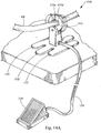
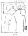
- Fig. 14A depicts an endoscope securing and positioning device 130 that is shown in use in fig. 14B .
- Use of endoscope securing and positioning device 130 is not limited to those endoscopes that enter through the mouth.
- Endoscope securing and positioning device 130 is placed near patient P .
- Endoscope securing and positioning device 130 has a clamp 131A, 131B that opens when foot pedal 134 is pressed, and closes when foot pedal 134 is released. Foot pedal 134 is connected via clamp release line 133 .
- Foot petal 134 and clamp release line 133 contain a fluid such as air. Compressing foot petal 134 compresses the fluid inside. As it does so, a pneumatic force is created such that it causes clamp 131A, 131B to overcome the opposing force of a spring (not shown) and separate apart.
- a mechanical drive cable could also be used to actuate/open clamp 131A, 131B .
- clamps 135 are lined with a rubber material (polyurethane, polytetrafluoroethylene, other suitable polymers, and other suitable materials may also be used) in order to prevent damage to elongated tubular body EB of endoscope as well as to increase friction there between.
- Feet 132 provide stability to endoscope securing and positioning device 130 to prevent it from tipping.
- Endoscope securing and positioning device 130 can be made out of many materials, including but not limited to, aluminum, stainless steel, polyurethane, polytetrafluoroethylene, other suitable polymers, and other suitable materials. Endoscope securing and positioning device 130 should be sufficiently heavy in order to maintain the position of elongated tubular body EB of endoscope. Thus, a weight of five pounds is generally sufficient although heavier or lighter devices are contemplated.
- Fig. 15 depicts another embodiment of an endoscope securing and positioning device 150 that is attached to a bed or table via bolts 151 .
- endoscope securing and positioning device 150 can be attached in a variety of different ways, including but not limited to, clamps.
- the gap at line A-A is about 10mm whereas the gap at line B-B is about 20mm. Greater or lesser gap distances can be used, however, the gap distance should be such that it holds elongated tubular body EB of endoscope in place.
- Endoscope securing and positioning device 150 can be made out of many materials, including but not limited to, aluminum, stainless steel, polyurethane, polytetrafluoroethylene, other suitable polymers, and other suitable materials.
- endoscope securing and positioning device 150 To use endoscope securing and positioning device 150 , the medical professional threads elongated tubular body EB of endoscope under arm 152 .
- Arm 152 is shaped in such a way that as elongated tubular body EB of endoscope attempts to un-rotate itself, the arm 152 tightens and maintains the position of elongated tubular body EB of endoscope.
- Arm 152 is lined 153 with rubber (polyurethane, polytetrafluoroethylene, other suitable polymers, and other suitable materials may also be used) in order to prevent damage to elongated tubular body EB of endoscope as well as to increase friction there between.
- Endoscope securing and positioning device 150 may also include a threaded portion so that the gap distances (A-A, B-B) can be adjusted.
Description
- The present patent document claims the benefit of the filing date under 35 U.S.C. § 119(e) of Provisional U.S. Patent Application Serial No.
60/797,123, filed May 3, 2006 - This invention relates to endoscopes used generally for visual examination of a body.
- Endoscopes are primarily used to visually examine parts of the body including the stomach, colon, intestine, and esophagus. In order to view an inner portion of the body, the medical professional will insert the endoscope into a patient through an orifice.
- At the handle portion of the endoscope are a number of controls for deflecting the tip of the endoscope that is within the patient. Such deflection allows the medical professional to better view the bodily interior. The medical professional normally manipulates the control features of the endoscope by holding the handle at chest level with his/her right hand.
- In addition to deflecting the tip of the endoscope by using the control handle, the medical professional also rotates the endoscope in order to move to and better view an area of the bodily interior. For example, when used orally, the medical professional rotates the device by having his/her free hand hold a portion of the endoscope just outside the patient's mouth and turning his/her hand from side-to-side. It is difficult for the medical professional to turn the endoscope to any great degree because the medical professional is limited by the degree of rotation that his/her wrist can turn. Once the medical professional reaches that limit, the medical professional must stop and re-grip the endoscope in order to further rotate the device.
- A medical professional can also rotate the device by fully extending the potion of the endoscope that remains outside the patient and then turning the device by twisting the hand that is holding the handle of the endoscope. However, the medical professional has less precision when rotating the device in this manner.
- The medical professional cannot maintain the rotated position of the endoscope without using his/her hand (or another person's hand) to hold the endoscope in place. This results in the medical professional losing the ability to perform other functions with that hand.
- Reference is directed to
WO 2005/099558 which relates to a system and method for orienting an endoscope shaft and operator control module. The operator control module includes an engaging mechanism that allows the operator control module to be disengaged from the endoscope shaft. This allows the operator control module to remain in the operator's preferred orientation and then be re-engaged to the endoscope shaft. Remotely powered tip articulation cables are also provided, thus allowing the operator control module the freedom of not having to remain mechanically attached to the endoscope shaft in a fixed position. When the operator wants to rotate the endoscope shaft axially and does not want the position of the operator control module to be changed, the operator control module engaging mechanism is disengaged, after which the endoscope shaft is rotated to the desired position, and the engaging mechanism is then re-engaged to the endoscope shaft or to a fixed feature on the shaft. Reference is also directed toWO 02/076541 US 5, 496,282 which relates to a belt for stabilizing an implanted peritoneal dialysis catheter exiting from the abdomen of a user and having a valve at one end. The belt includes a body of elasticized fabric designed to encircle the patient, two fasteners with hook and pile features, and a receptacle. In addition, a relatively small adhesive-backed member, having adhesive on its inner surface and having a pile member on its outer surface, surrounds a portion of the catheter tubing at a point near where the tubing exits the user. One of the two fasteners secures and stabilizes the tubing to the belt body by pressing against the pile outer surface of the adhesive-backed member and subsequently is secured to itself. The second fastener is used to further secure the tubing against the belt body at a distance from the one fastener. The receptacle, or envelope, integral to the belt body, is used to securely hold the valve end of the catheter against the belt body. - The scope of the present invention is set forth in the appended claims.
- A medical device for use with an endoscope having a handle and an elongated tubular portion extending from the handle is provided. The medical device includes an attachment portion adapted for attachment to the elongated tubular portion of the endoscope, the attachment portion including one of means for adjusting and means for securing the rotational position of the elongated tubular portion of the endoscope.
- Additionally, a medical device for use with an endoscope having a handle and an elongated tubular portion extending from the handle is provided. The medical device includes an attachment portion adapted for attaching to the - elongated tubular portion of the endoscope. The attachment portion includes means for rotating the elongated tubular portion of the endoscope.
- Further, a medical device for use with an endoscope having a handle and an elongated tubular portion extending from the handle is provided. The medical device includes a bite block having a proximal portion, a distal portion, an inner portion, and an outer portion. The inner portion contains a lumen. The lumen has an inner diameter that is greater than the outer diameter of the elongated tubular portion of the endoscope. The lumen is adapted to laterally receive the elongated tubular portion of an endoscope.
- Additionally, a medical device for use with an endoscope having a handle and an elongated tubular portion extending from the handle is provided. The medical device includes a belt and a clamp connected to the belt. The clamp is adapted to movably secure the elongated tubular portion of the endoscope.
- Furthermore, a medical device for use with an endoscope having a handle and an elongated tubular portion extending from the handle is provided. The medical device includes a cable having a proximal portion and a distal portion. The distal portion is attached to the elongated tubular portion of the endoscope. The medical device also includes a control device. The proximal portion of the cable is attached to the control device. The control device is adapted to control movement of the cable. The cable is adapted to control the movement of the elongated tubular portion of the endoscope.
- Additionally, a medical device for use with an endoscope having a handle and an elongated tubular portion extending from the handle is provided. The medical device includes a proximal portion configured to laterally receive and adjustably maintain a position of the elongated tubular portion of the endoscope and a distal portion configured to attach to a stable object.
- Furthermore, a medical device for maintaining the torque of an endoscope is provided. The medical device includes an endoscope having a handle, a proximal elongated tubular portion extending from the handle, and a distal elongated tubular portion being rotatable relative to the proximal elongated tubular portion. The medical device further includes a coupling; wherein the coupling is fixedly connected to one of the proximal elongated tubular portion of the endoscope and the distal elongated tubular portion of the endoscope; and wherein the coupling is releasably connected to the other of the proximal elongated tubular portion of the endoscope and the distal elongated tubular portion of the endoscope.
- In addition, a medical device for use with an endoscope having a handle and an elongated tubular portion extending from the handle is provided. The medical device includes a cuff adapted to fit around a portion of the elongated tubular portion extending from the handle and a locking mechanism adapted to retain the position of the cuff with respect to the elongated tubular portion of the endoscope.
- Furthermore, a method of maintaining the torque of an endoscope is provided. The method includes providing a device for maintaining the torque of an endoscope. The device includes a position engagement device adapted to maintain the position of an endoscope and a position disengagement device adapted to release the position of an endoscope. The method also includes positioning the endoscope within a patient and engaging the position engagement device.
- The embodiments will be further described in connection with the attached drawing figures. It is intended that the drawings included as a part of this specification be illustrative of the embodiments and should in no way be considered as a limitation on the scope of the invention.
-
Fig. 1A is a side-view of a patient depicting a use of an endoscope positioning device; -
Fig. 1B is a perspective view of an endoscope positioning device; -
Fig. 2 is a side-view of a patient depicting a use of an endoscope securing and positioning device; -
Fig. 3 is a side-view of a patient depicting a use of an endoscope securing and positioning device; -
Fig. 4 is a side-view of a patient depicting a use of an endoscope securing and positioning device; -
Fig. 5 is a side-view of a patient depicting a use of an endoscope securing and positioning device; -
Fig. 6A is a side-view of a patient depicting a use of an endoscope securing and positioning device; -
Fig. 6B is perspective view of a modified endoscope tube; -
Fig. 6C is a front-view of an endoscope securing and positioning device; -
Fig. 7 is a front view of a modified endoscope; -
Fig. 8 is a front view of a modified endoscope; -
Fig. 9 is a perspective view of a modified endoscope; and -
Fig. 10 is a front-view of an endoscope securing belt; -
Fig. 11A is a side-view of an endoscope securing and positioning device; -
Fig. 11B is a side view of a patient depicting a use of the endoscope securing and positioning device; -
Fig. 12A is a perspective view of an endoscope securing and positioning device; -
Fig. 12B is a side-view of a patient depicting a use of an endoscope securing and positioning device; -
Fig. 13 is a perspective view of an endoscope securing and positioning device; -
Fig. 14A is a perspective view of an endoscope securing and positioning device; -
Fig. 14B is a side-view of a patient depicting a use of an endoscope securing and positioning device; and -
Fig. 15 is a perspective view of an endoscope securing and positioning device. - The exemplary embodiments disclosed herein allow a medical professional to rotate an endoscope and/or maintain the rotated position of the endoscope.
- A more detailed description of the embodiments will now be given with reference to
figs. 1A-15 . Throughout the disclosure, like reference numerals and letters refer to like elements. The present invention is not limited to the embodiments illustrated; to the contrary, the present invention specifically contemplates other embodiments not illustrated but intended to be included in the claims. -
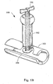
Figs. 1A and1B depict anendoscope positioning device 100 that aids in positioning and twisting an endoscope by giving the medical professional more leverage.Endoscope positioning device 100 includes anarm 102 that is pulled, pushed, or otherwise manipulated in order to rotate the endoscope.Endoscope positioning device 100 is attached to elongated tubular body EB (show infig. 1A ) of endoscope viaremovable cuff 103 that slips over elongated tubular body EB of endoscope.Adjustable screw 101 is used to securecuff 103 to elongated tubular body EB of endoscope.Adjustable screw 101 has a pad 104 (shown infig. 1B ) that frictionally engages endoscope without damaging the outer service of elongated tubular body EB of endoscope. Devices other than anadjustable screw 101 are also contemplated, including, but not limited to, a spring-loaded peg.Screw 101,arm 102, andcuff 103 can made from a variety of materials, including but not limited to, stainless steel, polyurethane, polytetrafluoroethylene, other suitable polymers, and other suitable materials. - To use
endoscope positioning device 100, the medicalprofessional places cuff 103 around elongated tubular body EB of endoscope.Screw 101 is tightened such that pad 104 (shown infig. 1B ) applies sufficient pressure to elongated tubular body EB of endoscope to prevent movement ofcuff 103 with respect to elongated tubular body EB of endoscope. To rotate the endoscope, the medical professional pulls or pushesarm 102. Use ofendoscope positioning device 100 is not limited to those endoscopes that enter through the mouth. -
Fig. 2 is a side-view of a patient depicting a use of endoscope securing andpositioning device 10. Endoscope securing andpositioning device 10 is placed into mouth M of patient P and has a proximal portion 10A and a distal portion 10B. Endoscope securing andpositioning device 10 maintains the rotation of an endoscope and also provides protection to elongated tubular body EB of the endoscope from teeth T of patient P. Patient P bites upon theouter portion 13 of endoscope securing and positioning device.Outer portion 13 of endoscope securing andpositioning device 10 can be made from any medically acceptable material that is resistant to being damaged by pressure exerted from the mouth M of patient P using teeth T. Such materials include, but are not limited to polyurethane, polytetrafluoroethylene, other suitable polymers, and other suitable materials. - The inside of endoscope securing and
positioning device 10 contains alumen 11 having a diameter that is slightly larger than the outer diameter of elongated tubular body EB of the endoscope in order to allow elongated tubular body EB of the endoscope to pass there through. Endoscope securing andpositioning device 10 also includes air holes 12 so that patient P can breathe through mouth M. - To use endoscope securing and
positioning device 10, the medical professional places endoscope securing andpositioning device 10 into mouth M of patient P such that distal portion 10B is nearest to the esophagus ofpatient P. Cuff 14 is placed around elongated tubular body EB of endoscope.Cuff 14 is a machined thermal plastic wedge-shaped attachment, however, it may also be made from a variety of other materials, including but not limited to, metal, polycarbonate, ABS, epoxies, and diallyl phthalate.Cuff 14 is 4"-5" long; however, other dimensions are also contemplated. The portion of elongated tubular body EB of theendoscope having cuff 14 is threaded throughlumen 11 of endoscope securing andpositioning device 10 at proximal portion 10A and is positioned as needed.Cuff 14 is engaged with the sides oflumen 11 so as to create a frictional force uponcuff 14 resulting in the position of elongated tubular body EB being maintained. - In order to reposition elongated tubular body EB,
cuff 14 is pulled in the proximal direction oflumen 11 in order to causelumen 11 not to engagecuff 14. Without the frictional force,cuff 14 no longer maintains the position of elongated tubular body EB;cuff 14 looses from around elongated tubular body EB thereby allowingcuff 14 to be repositioned along elongated tubular body EB; and elongated tubular body EB is able to be repositioned with respect to patient P. Once elongated tubular body EB is repositioned,cuff 14 is wedged back intolumen 11 to secure and maintain the position of elongated tubular body EB.Lumen 11 is lined with a rubber (polyurethane, polytetrafluoroethylene, other suitable polymers, and other suitable materials may also be used) in order to prevent damage to elongated tubular body EB of endoscope as well as to increase friction there between. -
Fig. 3 depicts another endoscope securing andpositioning device 20 similar to the one depicted infig. 2 . Infig. 3 , endoscope securing andpositioning device 20 has a proximal portion 20A and a distal portion 20B. Endoscope securing andpositioning device 20 maintains the rotation of elongated tubular body EB of the endoscope and also protects elongated tubular body EB of the endoscope from damage due to teeth T of patient P. Air holes 24 are provided so that patient P can breath through mouth M. - Patient P bites down on
outer portion 25 of endoscope securing andpositioning device 20.Outer portion 25 of endoscope securing andpositioning device 20 can be made from any medically acceptable material that is resistant to being damaged by pressure exerted from the mouth M of patient P using teeth T; polyurethane, polytetrafluoroethylene, other suitable polymers, and other suitable materials may be used. Endoscope securing andpositioning device 20 has alumen 23 having a diameter that is slightly larger than the outer diameter of elongated tubular body EB of the endoscope in order to allow elongated tubular body EB of the endoscope to pass there through. A spring loaded depressor 21, containing a spring 22, is used to maintain the position of elongated tubular body EB of the endoscope by applying pressure to the exterior of elongated tubular body EB of the endoscope so as to prevent lateral and rotational movement thereof. Depressor 21 can be made from any sturdy material, including, but not limited to, polyurethane, polytetrafluoroethylene, other suitable polymers, and other suitable materials. Spring 22 can be made from materials including, but not limited to, stainless steel. Tip ofdepressor 26 is contoured and lined with rubber (polyurethane, polytetrafluoroethylene, other suitable polymers, and other suitable materials may also be used) in order to prevent damage to elongated tubular body EB of endoscope as well as to increase friction there between. To disengage depressor 21, the medical professional pulls depressor 21 upward which releases elongated tubular body EB of endoscope. To engage depressor 21, the medical professional releases depressor 21 causing depressor 21 to apply pressure to the outer service of elongated tubular body EB. -
Fig. 4 depicts another endoscope securing andpositioning device 30 that is similar to those depicted infigs. 2 and3 . Infig. 4 , endoscope securing andpositioning device 30 has a proximal portion 30A and a distal portion 30B. Endoscope securing andpositioning device 30 maintains the rotation of elongated tubular body EB of the endoscope and also protects elongated tubular body EB of the endoscope from damage due to teeth T of patient P. Air holes 33 are provided so that patient P can breath through mouth M. - Patient P bites down on
outer portion 34 of endoscope securing andpositioning device 30.Outer portion 34 of endoscope securing andpositioning device 30 can be made from any medically acceptable material that is resistant to being damaged by pressure exerted from the mouth M of patient P using teeth T; polyurethane, polytetrafluoroethylene, other suitable polymers, and other suitable materials may also be used. Endoscope securing andpositioning device 30 contains alumen 32 having a diameter that is larger than the outer diameter of elongated tubular body EB of the endoscope in order to allow elongated tubular body EB of the endoscope to pass there through. Ascrew 31 is used to maintain the position of elongated tubular body EB of the endoscope by applying pressure on the exterior of elongated tubular body EB of the endoscope so as to prevent the lateral and rotational movement thereof.Screw 31 can be made from any sturdy material, including but not limited to, stainless steel.Screw 31 has a handle portion that is adapted to allowscrew 31 to be rotated without having to use a screwdriver. Tip ofscrew 35 is contoured and lined with rubber (polyurethane, polytetrafluoroethylene, other suitable polymers, and other suitable materials may also be used) in order to prevent damage to elongated tubular body EB of endoscope as well as to increase friction there between. - When
screw 31 is engaged,screw 31 holds elongated tubular body EB of the endoscope and prevents lateral and rotational movement of elongated tubular body EB of the endoscope. Therefore, because disengagement ofscrew 31 is necessary to adjust the position of elongated tubular body EB of the endoscope, the medical professional can maintain the position of elongated tubular body EB of the endoscope without needing to use a hand to hold elongated tubular body EB of the endoscope in the required position. To reposition elongated tubular body EB of the endoscope horizontally or rotationally, the medical professional disengages screw 31 by turningscrew 31 counterclockwise until it releases the hold on elongated tubular body EB of the turning it clockwise until it engages and holds elongated tubular body EB of the endoscope in place. -
Fig. 5 depicts another endoscope securing andpositioning device 40 similar to those depicted infigs. 2-4 . Endoscope securing andpositioning device 40 has a proximal portion 40A and a distal portion 40B. Endoscope securing andpositioning device 40 maintains the rotation of elongated tubular body EB of the endoscope and also protects elongated tubular body EB of the endoscope from damage due to teeth T of patient P. Air holes 43 are provided so that patient P can breath through mouth M. - Patient P bites down on
outer portion 44 of endoscope securing andpositioning device 40.Outer portion 44 of endoscope securing andpositioning device 40 can be made from any medically acceptable material that is resistant to being damaged by pressure exerted from the mouth M of patient P using teeth T; polyurethane, polytetrafluoroethylene, other suitable polymers, and other suitable materials may also be used. Endoscope securing andpositioning device 40 contains alumen 42 having a diameter that is larger than the outer diameter of elongated tubular body EB of the endoscope in order to allow elongated tubular body EB of the endoscope to pass there through. - Endoscope securing and
positioning device 40 includes aclamp 41 that is used to maintain the position of elongated tubular body EB of the endoscope.Clamp 41 can be made from materials including, but not limited to, stainless steel.Spring 46 biases handles together to closeclamp 41, such that clamp compresses elongated tubular body EB in order to maintain the position of the endoscope. To disengage clamps, the medical professional pulls apart clamp handles 41A, 41B. This releases clamp and allows the medical professional to reposition elongated tubular body EB.Clamp 41 is lined 45 with a rubber material (polyurethane, polytetrafluoroethylene, other suitable polymers, and other suitable materials may also be used) in order to prevent damage to elongated tubular body EB of endoscope as well as to increase friction there between. -
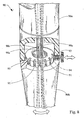
Figs. 6A and6C depict another endoscope securing andpositioning device 70 having a proximal portion 70A and a distal portion 70B. Endoscope securing andpositioning device 70 maintains the position of elongatedtubular body 71. In this embodiment, elongatedtubular body 71 of endoscope is modified such that it contains lockinggrooves 74 as depicted infigs. 6A and6B . Thus, when elongatedtubular body 71 is inserted throughlumen 72,grooves 74 engage with the locking teeth 75 (shown infig. 6C ) of endoscope securing andpositioning device 70.Grooves 74 engage with lockingteeth 75 to prevent the rotational movement of elongatedtubular body 71 but still allow for independent axial movement. Patient P bites with teeth T uponouter portion 76 of endoscope securing andpositioning device 70 in order to prevent elongatedtubular body 71 from damage due to teeth T. It is also contemplated that this device can contain air holes so that patient P can breath through the mouth M. - To rotate elongated
tubular body 71, the medicalprofessional releases button 73 and rotatesrace 77 until the desired position of elongatedtubular body 71 is reached. Once the desired position is reached, the medical professionalreengages locking button 73 by rocking it so thatbutton 73locks race 77 into place by having protrusion 73A engage with one of the multiple grooves 73B (as shown infig. 6C ). The dimension of grooves 73B is approximately .002" deep by .002" wide; however, other dimensions are contemplated. Because endoscope securing andpositioning device 70 maintains the position ofendoscope tube 71, the medical professional does not need to hold elongatedtubular body 71 in the rotated position. A sleeve having a grooved outer service could be disposed about the endoscope as opposed to modifying the outer surface thereof. -
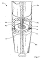
Fig. 7 depicts a modified endoscope. Distal portion 80B ofpositionable endoscope 80 is rotatable relative to proximal portion 80A. Proximal portion 80A ofpositionable endoscope 80 is fixedly attached tocoupling 81. Insidecoupling 81 is aball bearing 83, aspring 84 and bearing locks 82. - The medical professional rotates distal portion 80B of
positionable endoscope 80 which causesspring 84 to decompress asball bearing 83 rotates into one of the bearing locks 82. Onceball bearing 83 is secure in one of the bearing locks 82, the rotated position of distal portion 80B ofpositionable endoscope 80 will be maintained until sufficient rotational force is applied to distal portion 80B ofpositionable endoscope 80 to causespring 84 to decompress andball bearing 83 to rotate around into the nextadjacent bearing lock 82. In order to avoid breaking the inner workings 80C of the endoscope (which may include traditional control devices for controlling a camera and for deflecting the tip of the endoscope), care should be taken not to rotatecoupling 81 more than 180 degrees. -
Fig. 8 depicts anotherpositionable endoscope 90 like that depicted infig. 7 . Distal portion 90B ofpositionable endoscope 90 is rotatable relative to proximal portion 90A. Proximal portion 90A ofpositionable endoscope 90 is fixedly attached tocoupling 93.Coupling 93 contains lockingridges 91 which engage with lockingpeg 94 which is attached to spring-loadedknob 92. - To rotate distal portion 90B of
positionable endoscope 90, the medical professional pulls spring-loadedknob 92 to disengage it and rotates distal portion 90B ofpositionable endoscope 90. Once distal portion 90B is rotated into position, spring-loadedknob 92 is reengaged causing lockingpeg 94 to engage with lockingridge 91. In order to avoid breaking the inner workings 90C of the endoscope (which may include traditional control devices for controlling a camera and for deflecting the tip of the endoscope), care should be taken not to rotatecoupling 93 more than 180 degrees. -
Fig. 9 depicts a modified endoscope that is able to deflect and rotate elongatedtubular body 143. Positionable endoscope 140 is equipped with cables 142A, 142B that are located along the interior portion of the endoscope starting atwheel 141 through elongatedtubular body 143 where they become spirally attached to elongatedtubular body 143. Cables 142A, 142B are braided and made from stainless steel, although other configurations and materials are contemplated. - To use positionable endoscope 140, the medical device inserts distal end 140B of positionable endoscope 140 into the patient. To help position the device, the medical professional rotates
wheel 141 counter-clockwise causing cable 142A to retract, thereby causing distal end 140B of elongatedtubular body 143 to deflect and rotate in the direction that cable 142A pulls it. To un-deflect and un-rotate elongatedtubular body 143, the medical professional rotateswheel 141 in the opposite direction until cable 142A is unwound causing elongatedtubular body 143 to relax and straighten. To deflect the tip in the opposite direction, the medical professional rotateswheel 141 clockwise causing cable 142B to retract, thereby causing distal end 140B of elongatedtubular body 143 to deflect and rotate in the direction that cable 142B pulls it. To un-deflect and un-rotate elongatedtubular body 143, the medical professional rotateswheel 141 in the opposite direction until cable 142B is unwound causing elongatedtubular body 143 to relax and straighten. -
Fig. 10 is a front-view ofendoscope securing belt 50.Endoscope securing belt 50 includes aclamp 51 having clamp arms 51A, 51B.Clamp 51 maintains the position of elongated tubular body EB of the endoscope. To useendoscope securing belt 50, the medical professionalpositions belt strap 52 around his/her waist and connectsclasp 55.Belt strap 52 maintains the position ofendoscope securing belt 50 onto medical professional whenclasp 55 is engaged. - The medical professional disengages clamp 51 by pressing on
clamp release bulb 53 that is connected to clamp 51 via aclamp release line 54.Clamp release bulb 53 andclamp release line 54 contain a fluid such as air. Compressingclamp release bulb 53 compresses the fluid inside. As it does so, a pneumatic force is created such that it causes clamp arms 51A, 51B to overcome the opposing force of a spring (not shown) and separate apart. Alternatively, instead of using a fluid, a mechanical drive cable could also be used to actuate/open clamp arms 51A, 51B. - When clamp arms 51A, 51B are disengaged, elongated tubular body EB of the endoscope may be freely positioned into an orifice of a patient. Once elongated tubular body EB of the endoscope is in position, the medical professional reengages clamp 51 by releasing
clamp release bulb 53 causing clamp arms 51A, 51B to come together and hold elongated tubular body EB of the endoscope in place. -
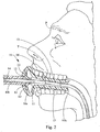
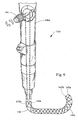
Figs. 11A and11B depict another endoscope securing andpositioning device 60. Infig. 11A , endoscope securing andpositioning device 60 is shown having a proximal portion 60A and a distal portion 60B. Endoscope securing andpositioning device 60 maintains the position of elongated tubular body EB of endoscope. Located at distal end 60B of endoscope securing andpositioning device 60 isbed clamp 69 that clamps to abed, table, or any other stable item near patient. Engaging and disengagingbed clamp 69 is controlled by pullingtrigger 68 that is attached to handle 67.Handle 67 is attached toarm 66 by lockable ball joint 65B to allow for rotation, lateral, and longitudinal movement ofarm 66.Arm 66 is attached toarm 64 via lockable ball joint 65A to allow for the rotational, lateral, and longitudinal movement ofarm 64. Alternatively,arms -
Clamp 62 is attached toarm 64 via lockable ball joint 65C to allow for rotational movement ofclamp 62.Clamp 62 is lined with a rubber material 63 (polyurethane, polytetrafluoroethylene, other suitable polymers, and other suitable materials may also be used) in order to prevent damage to elongated tubular body EB of endoscope as well as to increase friction there between.Clamp lock 61 locks clamp 62 around elongated tubular body EB of endoscope. -
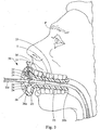
Fig. 11B depicts a use of the device depicted infig. 11A . Here,clamp lock 61 is engaged, thus causing lockingclamp 62 to maintain the position of elongated tubular body EB within patient P. To adjust elongated tubular body EB, the medicalprofessional moves arms lock 61 is disengaged causingclamp 62 to open and release its hold on elongated tubular body EB. Once elongated tubular body EB is positioned EB, clamplock 61 is reengaged. Use of endoscope securing andpositioning device 60 is not limited to those endoscope that enter through the mouth. -
Fig. 12A depicts an endoscope securing andpositioning device 110 that is shown in use infig. 12B . Endoscope securing andpositioning device 110 includes aboard 113 on which patent P rests.Board 113 is connected to acuff 112 for securing and positioning elongated tubular body EB of endoscope.Cuff 112 is lined with a rubber material 114 (polyurethane, polytetrafluoroethylene, other suitable polymers, and other suitable materials may also be used) in order to protect the outside service of elongated tubular body EB from damage. When locked using locking hinge 111B, cuff presses against elongated tubular body EB preventing lateral and rotational movement. When locking hinge 111B is disengaged, cuff opens at hinge 111A and allows elongated tubular body EB to be repositioned.Board 113,cuff 112, hinge 111A, and locking hinge 111B can be made from a variety of materials including, but not limited to, polyurethane, polytetrafluoroethylene, other suitable polymers, stainless steal, and other suitable materials. Use of endoscope securing andpositioning device 110 is not limited to those endoscopes that enter through the mouth. -
Fig. 13 depicts another embodiment of the endoscope securing and positioning device depicted infigs. 12A and12B . Endoscope securing andpositioning device 120 has alocking band 115 that removably attaches at 111C and 111D in order to prevent rotational and axial movement of elongated tubular body EB. Lockingband 115 can be made from a variety of materials, including, but not limited to, rubber. -
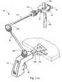
Fig. 14A depicts an endoscope securing andpositioning device 130 that is shown in use infig. 14B . Use of endoscope securing andpositioning device 130 is not limited to those endoscopes that enter through the mouth. Endoscope securing andpositioning device 130 is placed near patient P. Endoscope securing andpositioning device 130 has a clamp 131A, 131B that opens whenfoot pedal 134 is pressed, and closes whenfoot pedal 134 is released.Foot pedal 134 is connected viaclamp release line 133. -
Foot petal 134 andclamp release line 133 contain a fluid such as air. Compressingfoot petal 134 compresses the fluid inside. As it does so, a pneumatic force is created such that it causes clamp 131A, 131B to overcome the opposing force of a spring (not shown) and separate apart. Alternatively, instead of using a fluid, a mechanical drive cable could also be used to actuate/open clamp 131A, 131B. - While
foot pedal 134 pressed, elongated tubular body EB of endoscope is thread through clamp 131A, 131B and positioned. Once positioned,foot pedal 134 is released causing clamp 131A, 131B to close and maintain the position of elongated tubular body EB of endoscope. The interior surface ofclamps 135 is lined with a rubber material (polyurethane, polytetrafluoroethylene, other suitable polymers, and other suitable materials may also be used) in order to prevent damage to elongated tubular body EB of endoscope as well as to increase friction there between.Feet 132 provide stability to endoscope securing andpositioning device 130 to prevent it from tipping. Endoscope securing andpositioning device 130 can be made out of many materials, including but not limited to, aluminum, stainless steel, polyurethane, polytetrafluoroethylene, other suitable polymers, and other suitable materials. Endoscope securing andpositioning device 130 should be sufficiently heavy in order to maintain the position of elongated tubular body EB of endoscope. Thus, a weight of five pounds is generally sufficient although heavier or lighter devices are contemplated. -
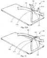
Fig. 15 depicts another embodiment of an endoscope securing andpositioning device 150 that is attached to a bed or table viabolts 151. Although bolted in this embodiment, endoscope securing andpositioning device 150 can be attached in a variety of different ways, including but not limited to, clamps. The gap at line A-A is about 10mm whereas the gap at line B-B is about 20mm. Greater or lesser gap distances can be used, however, the gap distance should be such that it holds elongated tubular body EB of endoscope in place. Endoscope securing andpositioning device 150 can be made out of many materials, including but not limited to, aluminum, stainless steel, polyurethane, polytetrafluoroethylene, other suitable polymers, and other suitable materials. - To use endoscope securing and
positioning device 150, the medical professional threads elongated tubular body EB of endoscope underarm 152.Arm 152 is shaped in such a way that as elongated tubular body EB of endoscope attempts to un-rotate itself, thearm 152 tightens and maintains the position of elongated tubular body EB of endoscope.Arm 152 is lined 153 with rubber (polyurethane, polytetrafluoroethylene, other suitable polymers, and other suitable materials may also be used) in order to prevent damage to elongated tubular body EB of endoscope as well as to increase friction there between. Endoscope securing andpositioning device 150 may also include a threaded portion so that the gap distances (A-A, B-B) can be adjusted. - The foregoing description and drawings are provided for illustrative purposes only and are not intended to limit the scope of the invention described herein or with regard to the details of its construction and manner of operation. It will be evident to one skilled in the art that modifications and variations may be made without departing from the scope of the invention. Changes in form and in the proportion of parts, as well as the substitution of equivalence, are contemplated as circumstances may suggest and render expedience; although specific terms have been employed, they are intended in a generic and descriptive sense only and not for the purpose of limiting the scope of the invention set forth in the following claims.
Claims (5)
- Apparatus for rotating an endoscope and maintaining the rotated position of the endoscope, comprising:an endoscope having a handle and an elongated tubular portion (71) extending from the haridle; anda medical device (70) for use with said endoscope, the medical device comprising:an outer part (76) having a proximal portion, a distal portion, an inner portion, and an outer portion, the inner portion containing a lumen, which has an inner diameter that is greater than the outer diameter of the elongated tubular portion of the endoscope andwhich is adapted to laterally receive the elongated tubular portion of an endoscope;an attachment portion adapted for attachment to the elongated tubular portion of the endoscope, the attachment portion including means for adjusting the rotational position of the elongated tubular portion of the endoscope; characterised in that the means for adjusting the rotational position of the elongated tubular portion of the endoscope comprises teeth (75) and the elongated tubular portion of the endoscope further comprises grooves (74) adapted for receiving the teeth.
- Apparatus according to Claim 1, wherein when elongated tubular body is inserted through said lumen, said grooves (74) engage with said teeth (75).
- Apparatus according to Claim 1 or Claim 2, wherein said grooves (74) engage with said teeth (75) to prevent the rotational movement of said elongated tubular portion (71), while still allowing for independent axial movement.
- Apparatus according to any one of claims 1 to 3, the means for adjusting the rotational position of the elongated tubular portion (71) of the endoscope further comprises a button (73).
- Apparatus according to Claim 4, wherein the means for adjusting the rotational position of the elongated tubular portion of the endoscope further comprises a race (77) having a plurality of grooves (73B) provided thereupon and said button (73) comprises a protrusion (73A);
wherein, to adjust the rotational position of the elongated tubular portion (71) of the endoscope, the user releases said button (73) and rotates said race (77) until the desired position of the elongated tubular portion (71) of the endoscope is reached; and wherein, to secure the rotational position of the elongated tubular portion (71) of the endoscope once said desired position is reached, the user reengages said button (73) by rocking it so that button (73) locks race (77) into place by having said protrusion (73A) engage with one of said plurality of grooves (73B) provided on the race (77).
Applications Claiming Priority (2)
| Application Number | Priority Date | Filing Date | Title |
|---|---|---|---|
| US79712306P | 2006-05-03 | 2006-05-03 | |
| PCT/US2007/010314 WO2007130311A2 (en) | 2006-05-03 | 2007-04-27 | Endoscope rotational and positioning apparatus and method |
Publications (2)
| Publication Number | Publication Date |
|---|---|
| EP2012649A2 EP2012649A2 (en) | 2009-01-14 |
| EP2012649B1 true EP2012649B1 (en) | 2017-07-12 |
Family
ID=38577551
Family Applications (1)
| Application Number | Title | Priority Date | Filing Date |
|---|---|---|---|
| EP07776403.3A Not-in-force EP2012649B1 (en) | 2006-05-03 | 2007-04-27 | Endoscope rotational and positioning apparatus |
Country Status (6)
| Country | Link |
|---|---|
| US (1) | US9307891B2 (en) |
| EP (1) | EP2012649B1 (en) |
| JP (1) | JP2009535158A (en) |
| AU (1) | AU2007248793B2 (en) |
| CA (1) | CA2651081A1 (en) |
| WO (1) | WO2007130311A2 (en) |
Families Citing this family (16)
| Publication number | Priority date | Publication date | Assignee | Title |
|---|---|---|---|---|
| US8333689B2 (en) * | 2008-05-13 | 2012-12-18 | Olympus Medical Systems Corp. | Medical operation device |
| US8939894B2 (en) * | 2009-03-31 | 2015-01-27 | Intuitive Surgical Operations, Inc. | Three-dimensional target devices, assemblies and methods for calibrating an endoscopic camera |
| JP5692728B2 (en) * | 2010-02-24 | 2015-04-01 | 国立大学法人 香川大学 | Endoscope insertion aid |
| US8764632B2 (en) * | 2010-04-08 | 2014-07-01 | Eric James Kezirian | Endoscopic device and system |
| US9717485B1 (en) | 2013-10-09 | 2017-08-01 | Daniel Glenn Doerr | Ergonomic multi-functional handle for use with a medical instrument |
| US10058311B1 (en) | 2013-10-09 | 2018-08-28 | Rogelio A. Insignares | Ergonomic multi-functional handle for use with a medical instrument |
| US9788856B2 (en) | 2014-03-11 | 2017-10-17 | Stryker European Holdings I, Llc | Endoscopic surgical systems and methods |
| JP2018517507A (en) | 2015-06-11 | 2018-07-05 | ハウメディカ・オステオニクス・コーポレイション | Spinal fixation targeting system and method for posterior spine surgery |
| EP3437540B1 (en) * | 2016-03-31 | 2021-11-03 | Keio University | Endoscope holder with gripping members and with elastic members |
| US10827910B2 (en) * | 2016-04-19 | 2020-11-10 | Druiden Lakartjänst Ab | Bite block for endoscopic examination with expanding means |
| IT201700090466A1 (en) * | 2017-08-04 | 2019-02-04 | Giuseppe Lijoi | SUPPORT DEVICE FOR MEDICAL INSTRUMENTS |
| US11224337B2 (en) | 2018-07-25 | 2022-01-18 | Skillhead Llc | Orophrangeal glove for use with a rigid bronchscope and a method |
| GB2589132B (en) * | 2019-11-22 | 2021-11-17 | Leo Garner Justin | A clamp for a bronchoscope or the like |
| US11964114B2 (en) | 2020-05-22 | 2024-04-23 | Acclarent, Inc. | Shaft deflection control assembly for ENT guide instrument |
| WO2023052243A1 (en) | 2021-09-28 | 2023-04-06 | Ambu A/S | An endoscope |
| DK181390B1 (en) * | 2022-01-28 | 2023-09-27 | Olesen Jeppe | A device for supporting probe and/or endoscope parts of medical devices introduced through the mouth of a patient |
Citations (2)
| Publication number | Priority date | Publication date | Assignee | Title |
|---|---|---|---|---|
| US4530354A (en) * | 1983-02-07 | 1985-07-23 | Froilan Faustino C | Endotrachael tube and holder |
| US6029668A (en) * | 1993-09-13 | 2000-02-29 | Freed; M. Simon | Endotracheal tube holder having both a safety clamp and a securing clamp |
Family Cites Families (35)
| Publication number | Priority date | Publication date | Assignee | Title |
|---|---|---|---|---|
| US4024858A (en) | 1975-01-30 | 1977-05-24 | Machida Endoscope Co., Ltd. | Endoscope |
| US4112936A (en) | 1976-09-27 | 1978-09-12 | Blachly Paul H | Bite block assembly adapted for adjustable mounting and holding of oral airways and method of using same |
| JPS6120567Y2 (en) * | 1978-08-24 | 1986-06-20 | ||
| JPS5532761A (en) | 1978-08-30 | 1980-03-07 | Hitachi Chem Co Ltd | Production of silicon carbide-coated graphite seal material |
| JPS59181122A (en) * | 1983-03-31 | 1984-10-15 | オリンパス光学工業株式会社 | Advance and retraction guide apparatus of endoscope |
| JPH0613723B2 (en) | 1985-09-20 | 1994-02-23 | 川崎製鉄株式会社 | Belt-side heat-sealing device for metal powder heat treatment |
| JPS6270501U (en) * | 1985-10-24 | 1987-05-06 | ||
| JPH0773568B2 (en) | 1986-02-17 | 1995-08-09 | オリンパス光学工業株式会社 | Endoscopic insertion aid |
| JPH01148233A (en) | 1987-12-07 | 1989-06-09 | Olympus Optical Co Ltd | Mouthpiece |
| US5409453A (en) | 1992-08-12 | 1995-04-25 | Vidamed, Inc. | Steerable medical probe with stylets |
| US5279597A (en) * | 1992-01-13 | 1994-01-18 | Arrow International Investment Corp. | Catheter compression clamp |
| US5674182A (en) * | 1993-02-26 | 1997-10-07 | Olympus Optical Co., Ltd. | Endoscope system including endoscope and protection cover |
| US5513633A (en) * | 1994-04-28 | 1996-05-07 | Islava; Steven T. | Endotracheal tube holder |
| US5402776A (en) * | 1994-04-28 | 1995-04-04 | Islava; Steven T. | Endotracheal tube holder |
| US5496260A (en) | 1994-05-16 | 1996-03-05 | Welch Allyn, Inc. | Torque override knob for endoscopes, borescopes, or guide tubes |
| US5496282A (en) * | 1994-12-12 | 1996-03-05 | Militzer; George G. | Apparatus and method to stabilize a peritoneal dialysis catheter |
| US5649956A (en) | 1995-06-07 | 1997-07-22 | Sri International | System and method for releasably holding a surgical instrument |
| US5626128A (en) * | 1995-08-31 | 1997-05-06 | University Of South Carolina | Endotracheal tube fixation device and method of using the same |
| DE19748500B4 (en) | 1997-11-03 | 2006-03-30 | Stm Medizintechnik Starnberg Gmbh | Feed device for a flexible endoscope shaft |
| NL1009440C2 (en) * | 1998-06-18 | 1999-12-21 | Johannes Alphonsus Van Hegelso | Assembly for fixing a tube for medical purposes in a patient's mouth. |
| US6293908B1 (en) * | 1999-02-12 | 2001-09-25 | Fuji Photo Optical Co., Ltd. | Mouthpiece and insertion assisting device for endoscope |
| JP2001275942A (en) * | 2000-03-31 | 2001-10-09 | Olympus Optical Co Ltd | Endoscope fixing tool |
| US6673012B2 (en) | 2000-04-19 | 2004-01-06 | Pentax Corporation | Control device for an endoscope |
| DE10055293A1 (en) * | 2000-11-03 | 2002-05-29 | Storz Karl Gmbh & Co Kg | Device for holding and positioning an endoscopic instrument |
| US6579300B2 (en) | 2001-01-18 | 2003-06-17 | Scimed Life Systems, Inc. | Steerable sphincterotome and methods for cannulation, papillotomy and sphincterotomy |
| US7160270B2 (en) | 2001-03-26 | 2007-01-09 | Curon Medical, Inc. | Systems and methods employing a bite block insert for positioning and stabilizing external instruments deployed within the body |
| WO2002076541A1 (en) * | 2001-03-26 | 2002-10-03 | Curon Medical, Inc. | Sytem and methods for positioning and stabiling external instruments |
| US6517549B1 (en) * | 2001-08-24 | 2003-02-11 | Core Dynamics, Inc. | Medical mouthpiece with elliptical passageway |
| DE60309713T2 (en) | 2002-07-05 | 2007-12-06 | JIREHSA MEDICAL (PROPRIETARY), Ltd. | HOLDING DEVICE FOR A MEDICAL TUBE |
| US6851424B2 (en) | 2002-08-08 | 2005-02-08 | Scimed Life Systems, Inc. | Mouthguard having device securing tab |
| WO2004032730A1 (en) | 2002-10-11 | 2004-04-22 | Koninklijke Philips Electronics N.V. | Control mechanism for an endoscope |
| WO2005009955A1 (en) * | 2003-07-31 | 2005-02-03 | Hetero Drugs Limited | Ezetimibe polymorphs |
| JP4490697B2 (en) | 2004-01-30 | 2010-06-30 | 富士フイルム株式会社 | Endoscope |
| JP3922284B2 (en) * | 2004-03-31 | 2007-05-30 | 有限会社エスアールジェイ | Holding device |
| US7192396B2 (en) | 2004-04-08 | 2007-03-20 | Scimed Life Systems, Inc. | System and method for orienting endoscope and operator control |
-
2007
- 2007-04-27 JP JP2009509627A patent/JP2009535158A/en active Pending
- 2007-04-27 CA CA002651081A patent/CA2651081A1/en not_active Abandoned
- 2007-04-27 US US11/796,525 patent/US9307891B2/en active Active
- 2007-04-27 EP EP07776403.3A patent/EP2012649B1/en not_active Not-in-force
- 2007-04-27 WO PCT/US2007/010314 patent/WO2007130311A2/en active Application Filing
- 2007-04-27 AU AU2007248793A patent/AU2007248793B2/en not_active Ceased
Patent Citations (2)
| Publication number | Priority date | Publication date | Assignee | Title |
|---|---|---|---|---|
| US4530354A (en) * | 1983-02-07 | 1985-07-23 | Froilan Faustino C | Endotrachael tube and holder |
| US6029668A (en) * | 1993-09-13 | 2000-02-29 | Freed; M. Simon | Endotracheal tube holder having both a safety clamp and a securing clamp |
Also Published As
| Publication number | Publication date |
|---|---|
| US9307891B2 (en) | 2016-04-12 |
| WO2007130311A2 (en) | 2007-11-15 |
| EP2012649A2 (en) | 2009-01-14 |
| US20070265497A1 (en) | 2007-11-15 |
| WO2007130311A3 (en) | 2008-05-02 |
| AU2007248793B2 (en) | 2013-06-20 |
| AU2007248793A1 (en) | 2007-11-15 |
| JP2009535158A (en) | 2009-10-01 |
| CA2651081A1 (en) | 2007-11-15 |
Similar Documents
| Publication | Publication Date | Title |
|---|---|---|
| EP2012649B1 (en) | Endoscope rotational and positioning apparatus | |
| JP2009535158A5 (en) | ||
| US20220031305A1 (en) | Endoscopic suturing system having external instrument channel | |
| US8535366B2 (en) | Implantable device delivery system handle and method of use | |
| AU2007270997B2 (en) | Medico-surgical tube assemblies | |
| US20030208187A1 (en) | Apparatus for positioning a medical instrument | |
| EP2415446A2 (en) | Cricoid manipulating apparatus for anesthesia assistance and tracheal intubation | |
| JP6771961B2 (en) | Anvil assembly and delivery system | |
| US10092440B2 (en) | Compression belts for selective chest compression following thoracic and cardiothoracic surgery and for selective abdominal compression following abdominal surgery | |
| JP6695957B2 (en) | Surgical device for stabilizing or resting moving tissue | |
| EP1744657B1 (en) | Scope dock | |
| CN112261915A (en) | Attachment device for a body-mountable medical instrument | |
| JP2023002624A (en) | System, apparatus, and method for patient positioning prior to, during, and/or after medical procedures | |
| JP2007537010A5 (en) | ||
| JP2017529142A (en) | Tool for tongue operation system | |
| CN219021111U (en) | Disposable light guide beam protective sleeve | |
| WO2019145669A1 (en) | Medico-surgical tube assemblies and mounts | |
| US20100305410A1 (en) | Appliance and method for controlling a patient's tongue during a medical procedure |
Legal Events
| Date | Code | Title | Description |
|---|---|---|---|
| PUAI | Public reference made under article 153(3) epc to a published international application that has entered the european phase |
Free format text: ORIGINAL CODE: 0009012 |
|
| 17P | Request for examination filed |
Effective date: 20081031 |
|
| AK | Designated contracting states |
Kind code of ref document: A2 Designated state(s): AT BE BG CH CY CZ DE DK EE ES FI FR GB GR HU IE IS IT LI LT LU LV MC MT NL PL PT RO SE SI SK TR |
|
| AX | Request for extension of the european patent |
Extension state: AL BA HR MK RS |
|
| DAX | Request for extension of the european patent (deleted) | ||
| 17Q | First examination report despatched |
Effective date: 20100429 |
|
| RAP1 | Party data changed (applicant data changed or rights of an application transferred) |
Owner name: COOK MEDICAL TECHNOLOGIES LLC |
|
| RAP1 | Party data changed (applicant data changed or rights of an application transferred) |
Owner name: COOK MEDICAL TECHNOLOGIES LLC |
|
| GRAP | Despatch of communication of intention to grant a patent |
Free format text: ORIGINAL CODE: EPIDOSNIGR1 |
|
| INTG | Intention to grant announced |
Effective date: 20170208 |
|
| RIN1 | Information on inventor provided before grant (corrected) |
Inventor name: RUCKER, BRIAN, K. Inventor name: HARDIN, DAVID, M. JR Inventor name: CARTER, MATTHEW, P. Inventor name: SOETERMANS, MAX Inventor name: WALLER, DAVID, F. Inventor name: JONES, BRIAN, K. Inventor name: BROWN, HILBERT, D. Inventor name: KENNEDY, KENNETH, C. |
|
| RIN1 | Information on inventor provided before grant (corrected) |
Inventor name: JONES, BRIAN, K. Inventor name: BROWN, HILBERT, D. Inventor name: HARDIN, DAVID, M. JR Inventor name: SOETERMANS, MAX Inventor name: WALLER, DAVID, F. Inventor name: KENNEDY, KENNETH, C. Inventor name: CARTER, MATTHEW, P. Inventor name: RUCKER, BRIAN, K. |
|
| GRAS | Grant fee paid |
Free format text: ORIGINAL CODE: EPIDOSNIGR3 |
|
| GRAA | (expected) grant |
Free format text: ORIGINAL CODE: 0009210 |
|
| AK | Designated contracting states |
Kind code of ref document: B1 Designated state(s): AT BE BG CH CY CZ DE DK EE ES FI FR GB GR HU IE IS IT LI LT LU LV MC MT NL PL PT RO SE SI SK TR |
|
| REG | Reference to a national code |
Ref country code: GB Ref legal event code: FG4D |
|
| REG | Reference to a national code |
Ref country code: CH Ref legal event code: EP |
|
| REG | Reference to a national code |
Ref country code: AT Ref legal event code: REF Ref document number: 907553 Country of ref document: AT Kind code of ref document: T Effective date: 20170715 |
|
| REG | Reference to a national code |
Ref country code: IE Ref legal event code: FG4D |
|
| REG | Reference to a national code |
Ref country code: DE Ref legal event code: R096 Ref document number: 602007051614 Country of ref document: DE |
|
| REG | Reference to a national code |
Ref country code: NL Ref legal event code: MP Effective date: 20170712 |
|
| REG | Reference to a national code |
Ref country code: LT Ref legal event code: MG4D |
|
| REG | Reference to a national code |
Ref country code: AT Ref legal event code: MK05 Ref document number: 907553 Country of ref document: AT Kind code of ref document: T Effective date: 20170712 |
|
| PG25 | Lapsed in a contracting state [announced via postgrant information from national office to epo] |
Ref country code: NL Free format text: LAPSE BECAUSE OF FAILURE TO SUBMIT A TRANSLATION OF THE DESCRIPTION OR TO PAY THE FEE WITHIN THE PRESCRIBED TIME-LIMIT Effective date: 20170712 Ref country code: FI Free format text: LAPSE BECAUSE OF FAILURE TO SUBMIT A TRANSLATION OF THE DESCRIPTION OR TO PAY THE FEE WITHIN THE PRESCRIBED TIME-LIMIT Effective date: 20170712 Ref country code: SE Free format text: LAPSE BECAUSE OF FAILURE TO SUBMIT A TRANSLATION OF THE DESCRIPTION OR TO PAY THE FEE WITHIN THE PRESCRIBED TIME-LIMIT Effective date: 20170712 Ref country code: AT Free format text: LAPSE BECAUSE OF FAILURE TO SUBMIT A TRANSLATION OF THE DESCRIPTION OR TO PAY THE FEE WITHIN THE PRESCRIBED TIME-LIMIT Effective date: 20170712 Ref country code: LT Free format text: LAPSE BECAUSE OF FAILURE TO SUBMIT A TRANSLATION OF THE DESCRIPTION OR TO PAY THE FEE WITHIN THE PRESCRIBED TIME-LIMIT Effective date: 20170712 |
|
| PG25 | Lapsed in a contracting state [announced via postgrant information from national office to epo] |
Ref country code: IS Free format text: LAPSE BECAUSE OF FAILURE TO SUBMIT A TRANSLATION OF THE DESCRIPTION OR TO PAY THE FEE WITHIN THE PRESCRIBED TIME-LIMIT Effective date: 20171112 Ref country code: PL Free format text: LAPSE BECAUSE OF FAILURE TO SUBMIT A TRANSLATION OF THE DESCRIPTION OR TO PAY THE FEE WITHIN THE PRESCRIBED TIME-LIMIT Effective date: 20170712 Ref country code: BG Free format text: LAPSE BECAUSE OF FAILURE TO SUBMIT A TRANSLATION OF THE DESCRIPTION OR TO PAY THE FEE WITHIN THE PRESCRIBED TIME-LIMIT Effective date: 20171012 Ref country code: GR Free format text: LAPSE BECAUSE OF FAILURE TO SUBMIT A TRANSLATION OF THE DESCRIPTION OR TO PAY THE FEE WITHIN THE PRESCRIBED TIME-LIMIT Effective date: 20171013 Ref country code: LV Free format text: LAPSE BECAUSE OF FAILURE TO SUBMIT A TRANSLATION OF THE DESCRIPTION OR TO PAY THE FEE WITHIN THE PRESCRIBED TIME-LIMIT Effective date: 20170712 Ref country code: ES Free format text: LAPSE BECAUSE OF FAILURE TO SUBMIT A TRANSLATION OF THE DESCRIPTION OR TO PAY THE FEE WITHIN THE PRESCRIBED TIME-LIMIT Effective date: 20170712 |
|
| REG | Reference to a national code |
Ref country code: DE Ref legal event code: R097 Ref document number: 602007051614 Country of ref document: DE |
|
| PG25 | Lapsed in a contracting state [announced via postgrant information from national office to epo] |
Ref country code: CZ Free format text: LAPSE BECAUSE OF FAILURE TO SUBMIT A TRANSLATION OF THE DESCRIPTION OR TO PAY THE FEE WITHIN THE PRESCRIBED TIME-LIMIT Effective date: 20170712 Ref country code: DK Free format text: LAPSE BECAUSE OF FAILURE TO SUBMIT A TRANSLATION OF THE DESCRIPTION OR TO PAY THE FEE WITHIN THE PRESCRIBED TIME-LIMIT Effective date: 20170712 Ref country code: RO Free format text: LAPSE BECAUSE OF FAILURE TO SUBMIT A TRANSLATION OF THE DESCRIPTION OR TO PAY THE FEE WITHIN THE PRESCRIBED TIME-LIMIT Effective date: 20170712 |
|
| PLBE | No opposition filed within time limit |
Free format text: ORIGINAL CODE: 0009261 |
|
| STAA | Information on the status of an ep patent application or granted ep patent |
Free format text: STATUS: NO OPPOSITION FILED WITHIN TIME LIMIT |
|
| PG25 | Lapsed in a contracting state [announced via postgrant information from national office to epo] |
Ref country code: SK Free format text: LAPSE BECAUSE OF FAILURE TO SUBMIT A TRANSLATION OF THE DESCRIPTION OR TO PAY THE FEE WITHIN THE PRESCRIBED TIME-LIMIT Effective date: 20170712 Ref country code: IT Free format text: LAPSE BECAUSE OF FAILURE TO SUBMIT A TRANSLATION OF THE DESCRIPTION OR TO PAY THE FEE WITHIN THE PRESCRIBED TIME-LIMIT Effective date: 20170712 Ref country code: EE Free format text: LAPSE BECAUSE OF FAILURE TO SUBMIT A TRANSLATION OF THE DESCRIPTION OR TO PAY THE FEE WITHIN THE PRESCRIBED TIME-LIMIT Effective date: 20170712 |
|
| 26N | No opposition filed |
Effective date: 20180413 |
|
| PG25 | Lapsed in a contracting state [announced via postgrant information from national office to epo] |
Ref country code: SI Free format text: LAPSE BECAUSE OF FAILURE TO SUBMIT A TRANSLATION OF THE DESCRIPTION OR TO PAY THE FEE WITHIN THE PRESCRIBED TIME-LIMIT Effective date: 20170712 |
|
| PG25 | Lapsed in a contracting state [announced via postgrant information from national office to epo] |
Ref country code: MC Free format text: LAPSE BECAUSE OF FAILURE TO SUBMIT A TRANSLATION OF THE DESCRIPTION OR TO PAY THE FEE WITHIN THE PRESCRIBED TIME-LIMIT Effective date: 20170712 |
|
| REG | Reference to a national code |
Ref country code: CH Ref legal event code: PL |
|
| REG | Reference to a national code |
Ref country code: BE Ref legal event code: MM Effective date: 20180430 |
|
| PG25 | Lapsed in a contracting state [announced via postgrant information from national office to epo] |
Ref country code: LU Free format text: LAPSE BECAUSE OF NON-PAYMENT OF DUE FEES Effective date: 20180427 |
|
| PG25 | Lapsed in a contracting state [announced via postgrant information from national office to epo] |
Ref country code: CH Free format text: LAPSE BECAUSE OF NON-PAYMENT OF DUE FEES Effective date: 20180430 Ref country code: LI Free format text: LAPSE BECAUSE OF NON-PAYMENT OF DUE FEES Effective date: 20180430 Ref country code: BE Free format text: LAPSE BECAUSE OF NON-PAYMENT OF DUE FEES Effective date: 20180430 |
|
| PG25 | Lapsed in a contracting state [announced via postgrant information from national office to epo] |
Ref country code: FR Free format text: LAPSE BECAUSE OF NON-PAYMENT OF DUE FEES Effective date: 20180430 |
|
| PG25 | Lapsed in a contracting state [announced via postgrant information from national office to epo] |
Ref country code: MT Free format text: LAPSE BECAUSE OF NON-PAYMENT OF DUE FEES Effective date: 20180427 |
|
| PG25 | Lapsed in a contracting state [announced via postgrant information from national office to epo] |
Ref country code: TR Free format text: LAPSE BECAUSE OF FAILURE TO SUBMIT A TRANSLATION OF THE DESCRIPTION OR TO PAY THE FEE WITHIN THE PRESCRIBED TIME-LIMIT Effective date: 20170712 |
|
| PG25 | Lapsed in a contracting state [announced via postgrant information from national office to epo] |
Ref country code: HU Free format text: LAPSE BECAUSE OF FAILURE TO SUBMIT A TRANSLATION OF THE DESCRIPTION OR TO PAY THE FEE WITHIN THE PRESCRIBED TIME-LIMIT; INVALID AB INITIO Effective date: 20070427 Ref country code: PT Free format text: LAPSE BECAUSE OF FAILURE TO SUBMIT A TRANSLATION OF THE DESCRIPTION OR TO PAY THE FEE WITHIN THE PRESCRIBED TIME-LIMIT Effective date: 20170712 |
|
| PG25 | Lapsed in a contracting state [announced via postgrant information from national office to epo] |
Ref country code: CY Free format text: LAPSE BECAUSE OF FAILURE TO SUBMIT A TRANSLATION OF THE DESCRIPTION OR TO PAY THE FEE WITHIN THE PRESCRIBED TIME-LIMIT Effective date: 20170712 |
|
| PGFP | Annual fee paid to national office [announced via postgrant information from national office to epo] |
Ref country code: IE Payment date: 20220328 Year of fee payment: 16 Ref country code: GB Payment date: 20220325 Year of fee payment: 16 |
|
| PGFP | Annual fee paid to national office [announced via postgrant information from national office to epo] |
Ref country code: DE Payment date: 20220318 Year of fee payment: 16 |
|
| REG | Reference to a national code |
Ref country code: DE Ref legal event code: R119 Ref document number: 602007051614 Country of ref document: DE |
|
| GBPC | Gb: european patent ceased through non-payment of renewal fee |
Effective date: 20230427 |
|
| PG25 | Lapsed in a contracting state [announced via postgrant information from national office to epo] |
Ref country code: GB Free format text: LAPSE BECAUSE OF NON-PAYMENT OF DUE FEES Effective date: 20230427 |
|
| PG25 | Lapsed in a contracting state [announced via postgrant information from national office to epo] |
Ref country code: GB Free format text: LAPSE BECAUSE OF NON-PAYMENT OF DUE FEES Effective date: 20230427 Ref country code: DE Free format text: LAPSE BECAUSE OF NON-PAYMENT OF DUE FEES Effective date: 20231103 |
|
| REG | Reference to a national code |
Ref country code: IE Ref legal event code: MM4A |
|
| PG25 | Lapsed in a contracting state [announced via postgrant information from national office to epo] |
Ref country code: IE Free format text: LAPSE BECAUSE OF NON-PAYMENT OF DUE FEES Effective date: 20230427 |