JP2018517507A - Spinal fixation targeting system and method for posterior spine surgery - Google Patents
Spinal fixation targeting system and method for posterior spine surgery Download PDFInfo
- Publication number
- JP2018517507A JP2018517507A JP2017564102A JP2017564102A JP2018517507A JP 2018517507 A JP2018517507 A JP 2018517507A JP 2017564102 A JP2017564102 A JP 2017564102A JP 2017564102 A JP2017564102 A JP 2017564102A JP 2018517507 A JP2018517507 A JP 2018517507A
- Authority
- JP
- Japan
- Prior art keywords
- joint
- targeting system
- pedicle
- single pedicle
- connector
- Prior art date
- Legal status (The legal status is an assumption and is not a legal conclusion. Google has not performed a legal analysis and makes no representation as to the accuracy of the status listed.)
- Pending
Links
- 230000008685 targeting Effects 0.000 title claims abstract description 724
- 238000001356 surgical procedure Methods 0.000 title claims abstract description 444
- 238000000034 method Methods 0.000 title claims abstract description 186
- 210000004197 pelvis Anatomy 0.000 claims description 42
- 241000270295 Serpentes Species 0.000 claims description 41
- 230000008878 coupling Effects 0.000 claims description 33
- 238000010168 coupling process Methods 0.000 claims description 33
- 238000005859 coupling reaction Methods 0.000 claims description 33
- 230000013011 mating Effects 0.000 claims description 29
- 230000008569 process Effects 0.000 claims description 27
- 238000003780 insertion Methods 0.000 claims description 20
- 230000037431 insertion Effects 0.000 claims description 20
- 238000003825 pressing Methods 0.000 claims description 14
- 230000000087 stabilizing effect Effects 0.000 claims description 12
- 238000003384 imaging method Methods 0.000 claims description 11
- 238000007373 indentation Methods 0.000 claims description 9
- 230000006641 stabilisation Effects 0.000 claims description 6
- 238000011105 stabilization Methods 0.000 claims description 6
- 238000013519 translation Methods 0.000 claims description 4
- 238000005452 bending Methods 0.000 claims description 2
- 238000010586 diagram Methods 0.000 description 24
- 210000000115 thoracic cavity Anatomy 0.000 description 24
- 210000001519 tissue Anatomy 0.000 description 23
- 230000003447 ipsilateral effect Effects 0.000 description 13
- 238000006243 chemical reaction Methods 0.000 description 12
- 230000009977 dual effect Effects 0.000 description 10
- 210000003484 anatomy Anatomy 0.000 description 8
- 230000008859 change Effects 0.000 description 7
- 230000004927 fusion Effects 0.000 description 6
- 230000006870 function Effects 0.000 description 5
- 210000004705 lumbosacral region Anatomy 0.000 description 4
- 239000000463 material Substances 0.000 description 4
- 230000008901 benefit Effects 0.000 description 3
- 230000004313 glare Effects 0.000 description 3
- 238000003786 synthesis reaction Methods 0.000 description 3
- 208000032765 Device extrusion Diseases 0.000 description 2
- 230000002411 adverse Effects 0.000 description 2
- 239000008280 blood Substances 0.000 description 2
- 210000004369 blood Anatomy 0.000 description 2
- 210000000988 bone and bone Anatomy 0.000 description 2
- 230000000694 effects Effects 0.000 description 2
- 239000002184 metal Substances 0.000 description 2
- 238000002324 minimally invasive surgery Methods 0.000 description 2
- 230000004048 modification Effects 0.000 description 2
- 238000012986 modification Methods 0.000 description 2
- 210000003205 muscle Anatomy 0.000 description 2
- 210000005036 nerve Anatomy 0.000 description 2
- 229920000642 polymer Polymers 0.000 description 2
- 230000005855 radiation Effects 0.000 description 2
- 230000002829 reductive effect Effects 0.000 description 2
- 230000014616 translation Effects 0.000 description 2
- 238000012800 visualization Methods 0.000 description 2
- 210000002517 zygapophyseal joint Anatomy 0.000 description 2
- SCLSKEHAOFJQCH-UHFFFAOYSA-N CCCC1C23C1CCC2C3 Chemical compound CCCC1C23C1CCC2C3 SCLSKEHAOFJQCH-UHFFFAOYSA-N 0.000 description 1
- 229920004943 Delrin® Polymers 0.000 description 1
- 208000006097 Spinal Dysraphism Diseases 0.000 description 1
- 241000722921 Tulipa gesneriana Species 0.000 description 1
- 230000000903 blocking effect Effects 0.000 description 1
- 230000001010 compromised effect Effects 0.000 description 1
- 238000005516 engineering process Methods 0.000 description 1
- 238000002594 fluoroscopy Methods 0.000 description 1
- 239000007943 implant Substances 0.000 description 1
- 230000006872 improvement Effects 0.000 description 1
- 208000014674 injury Diseases 0.000 description 1
- 230000002427 irreversible effect Effects 0.000 description 1
- 230000000670 limiting effect Effects 0.000 description 1
- 238000004519 manufacturing process Methods 0.000 description 1
- 230000007246 mechanism Effects 0.000 description 1
- 230000003287 optical effect Effects 0.000 description 1
- 238000011084 recovery Methods 0.000 description 1
- 230000009467 reduction Effects 0.000 description 1
- 210000004872 soft tissue Anatomy 0.000 description 1
- 210000000278 spinal cord Anatomy 0.000 description 1
- 230000008733 trauma Effects 0.000 description 1
Images


Classifications
-
- A—HUMAN NECESSITIES
- A61—MEDICAL OR VETERINARY SCIENCE; HYGIENE
- A61B—DIAGNOSIS; SURGERY; IDENTIFICATION
- A61B17/00—Surgical instruments, devices or methods, e.g. tourniquets
- A61B17/56—Surgical instruments or methods for treatment of bones or joints; Devices specially adapted therefor
- A61B17/58—Surgical instruments or methods for treatment of bones or joints; Devices specially adapted therefor for osteosynthesis, e.g. bone plates, screws, setting implements or the like
- A61B17/68—Internal fixation devices, including fasteners and spinal fixators, even if a part thereof projects from the skin
- A61B17/70—Spinal positioners or stabilisers ; Bone stabilisers comprising fluid filler in an implant
- A61B17/7074—Tools specially adapted for spinal fixation operations other than for bone removal or filler handling
-
- A—HUMAN NECESSITIES
- A61—MEDICAL OR VETERINARY SCIENCE; HYGIENE
- A61B—DIAGNOSIS; SURGERY; IDENTIFICATION
- A61B17/00—Surgical instruments, devices or methods, e.g. tourniquets
- A61B17/56—Surgical instruments or methods for treatment of bones or joints; Devices specially adapted therefor
- A61B17/58—Surgical instruments or methods for treatment of bones or joints; Devices specially adapted therefor for osteosynthesis, e.g. bone plates, screws, setting implements or the like
- A61B17/88—Osteosynthesis instruments; Methods or means for implanting or extracting internal or external fixation devices
-
- A—HUMAN NECESSITIES
- A61—MEDICAL OR VETERINARY SCIENCE; HYGIENE
- A61B—DIAGNOSIS; SURGERY; IDENTIFICATION
- A61B90/00—Instruments, implements or accessories specially adapted for surgery or diagnosis and not covered by any of the groups A61B1/00 - A61B50/00, e.g. for luxation treatment or for protecting wound edges
- A61B90/10—Instruments, implements or accessories specially adapted for surgery or diagnosis and not covered by any of the groups A61B1/00 - A61B50/00, e.g. for luxation treatment or for protecting wound edges for stereotaxic surgery, e.g. frame-based stereotaxis
- A61B90/11—Instruments, implements or accessories specially adapted for surgery or diagnosis and not covered by any of the groups A61B1/00 - A61B50/00, e.g. for luxation treatment or for protecting wound edges for stereotaxic surgery, e.g. frame-based stereotaxis with guides for needles or instruments, e.g. arcuate slides or ball joints
-
- A—HUMAN NECESSITIES
- A61—MEDICAL OR VETERINARY SCIENCE; HYGIENE
- A61B—DIAGNOSIS; SURGERY; IDENTIFICATION
- A61B90/00—Instruments, implements or accessories specially adapted for surgery or diagnosis and not covered by any of the groups A61B1/00 - A61B50/00, e.g. for luxation treatment or for protecting wound edges
- A61B90/50—Supports for surgical instruments, e.g. articulated arms
-
- A—HUMAN NECESSITIES
- A61—MEDICAL OR VETERINARY SCIENCE; HYGIENE
- A61B—DIAGNOSIS; SURGERY; IDENTIFICATION
- A61B17/00—Surgical instruments, devices or methods, e.g. tourniquets
- A61B17/16—Bone cutting, breaking or removal means other than saws, e.g. Osteoclasts; Drills or chisels for bones; Trepans
- A61B17/17—Guides or aligning means for drills, mills, pins or wires
- A61B17/1739—Guides or aligning means for drills, mills, pins or wires specially adapted for particular parts of the body
- A61B17/1757—Guides or aligning means for drills, mills, pins or wires specially adapted for particular parts of the body for the spine
Abstract
後方脊椎手術のための単椎弓根標的化システム(100)は、第1のジョイント構成要素と、第1のジョイント構成要素を単一の椎弓根(176)に固定するためのファスナ(110)と、第1のジョイント構成要素と嵌合して3回転自由度を有する第1のジョイントを形成する第2のジョイント構成要素を有する位置決めアーム(620)と、脊椎手術装置を位置決めアーム(620)に結合するためのコネクタ(130)と、を含む。コネクタ(130)は、脊椎手術装置の第4のジョイント構成要素と嵌合して3回転自由度を有する第2のジョイントを形成する第3のジョイント構成要素を有する。後方脊椎手術のための単椎弓根標的化方法は、ファスナ(110)を単一の椎弓根(176)に固定するステップと、脊椎手術装置(150)をファスナに接続するマニピュレータ(210)のジョイントを操作することによって、椎骨の椎弓根(176)に対する後方脊椎手術装置の3並進自由度および3回転自由度を調整するステップと、を含む。
【選択図】 図1BA single pedicle targeting system (100) for posterior spine surgery includes a first joint component and a fastener (110) for securing the first joint component to a single pedicle (176). ), A positioning arm (620) having a second joint component that mates with the first joint component to form a first joint having three degrees of freedom of rotation, and a spinal surgery device positioning arm (620) ) To the connector (130). The connector (130) has a third joint component that mates with a fourth joint component of the spinal surgery apparatus to form a second joint having three rotational degrees of freedom. A single pedicle targeting method for posterior spine surgery includes securing a fastener (110) to a single pedicle (176) and a manipulator (210) for connecting a spinal surgery device (150) to the fastener. Adjusting the three translational degrees of freedom and the three degrees of freedom of rotation of the posterior spine surgical device relative to the vertebra pedicle (176).
[Selection] Figure 1B
Description
関連出願の相互参照
本出願は、2015年6月11日に出願された米国仮出願第62/174,342号、2015年10月12日に出願された米国仮出願第62/240,231号および2015年11月10日に出願された米国仮出願第62/253,280号のそれぞれの優先権の利益を主張する。上記出願のすべては、その全体が参照により本明細書に組み込まれる。
CROSS REFERENCE TO RELATED APPLICATIONS This application is based on US Provisional Application No. 62 / 174,342, filed Jun. 11, 2015, and US Provisional Application No. 62 / 240,231, filed Oct. 12, 2015. And claims the benefit of each priority of US Provisional Application No. 62 / 253,280, filed Nov. 10, 2015. All of the above applications are incorporated herein by reference in their entirety.
胸椎および腰椎の手術では、関心領域は、通常、患者の後(背中)側からアクセスされる。医師は、皮膚を切開し、筋肉および他の介在組織を後退させて、手術を必要とする脊椎部分または複数の脊椎部分にアクセスする。場合によっては、外科医は、1つまたは複数の脊椎部分から骨材料をさらに取り除き、より深い箇所にある領域へアクセスすることができる。2つの腰椎部分が一緒に融合された経椎間孔腰椎椎体間固定の例では、外科医は、脊椎を刺激して椎間関節の深部まで脊椎を通る神経根の間の開口を椎間板スペースへのより良いアクセスに使用することができるように、2つの腰椎部分間の椎間関節の一部を取り除くことができる。 In thoracic and lumbar surgery, the region of interest is usually accessed from the back (back) side of the patient. The physician incises the skin and retracts the muscles and other intervening tissues to access the spinal segment or segments that require surgery. In some cases, the surgeon may further remove bone material from one or more spine portions to access deeper areas. In the translumbar lumbar interbody fusion example where the two lumbar segments are fused together, the surgeon stimulates the spine to open the opening between the nerve roots through the spine to the depth of the facet joint to the disc space. The part of the facet joint between the two lumbar parts can be removed so that it can be used for better access.
従来の観血脊椎手術では、切開は一般に約3〜6インチの長さであり、失血および回復時間は重要である。一方、後方アクセスを伴う「低侵襲」手術は、1インチほどの小さな切開を使用して実施することができ、患者は手術の日または翌日に退院することができる。そのような低侵襲の処置は、皮膚、筋肉および他の介在組織をかたわらに保持するための引き込み装置を利用する。これらの引き込み装置は、2つ以上の椎骨、または手術台に取り付けられた固定具のような外部システムに固定される。 In conventional open spine surgery, the incision is typically about 3-6 inches long, and blood loss and recovery time are important. On the other hand, “minimally invasive” surgery with posterior access can be performed using an incision as small as one inch, and the patient can be discharged on the day of surgery or the next day. Such minimally invasive procedures utilize retraction devices to hold skin, muscle, and other intervening tissues. These retractors are secured to an external system such as two or more vertebrae or a fixture attached to the operating table.
一実施形態では、後方脊椎手術のための単椎弓根標的化システムは、第1のジョイント構成要素と、第1のジョイント構成要素を椎骨の単一の椎弓根に固定するためのファスナと、第1のジョイント構成要素と嵌合して3回転自由度を有する第1のジョイントを形成する第2のジョイント構成要素を有する位置決めアームと、脊椎手術装置を位置決めアームに結合するためのコネクタと、を含む。コネクタは、脊椎手術装置の第4のジョイント構成要素と嵌合して3回転自由度を有する第2のジョイントを形成する第3のジョイント構成要素を有する。 In one embodiment, a single pedicle targeting system for posterior spine surgery includes a first joint component and a fastener for securing the first joint component to a single pedicle of a vertebra. A positioning arm having a second joint component mating with the first joint component to form a first joint having three rotational degrees of freedom; and a connector for coupling the spinal surgery device to the positioning arm ,including. The connector has a third joint component that mates with a fourth joint component of the spinal surgery device to form a second joint having three rotational degrees of freedom.
一実施形態では、後方脊椎手術のための単椎弓根標的化方法は、ファスナを椎骨の単一の椎弓根に固定するステップと、ファスナに取り付けられたマニピュレータを介して脊椎手術装置を椎弓根に固定するステップと、マニピュレータを調整して、椎弓根に対する3並進自由度および3回転自由度を用いて脊椎手術装置の位置および向きを規定し、手術部位を後方から標的に定めるステップと、を含む。 In one embodiment, a single pedicle targeting method for posterior spine surgery includes the steps of securing a fastener to a single pedicle of a vertebra and a spinal surgery device via a manipulator attached to the fastener. Securing to the pedicle and adjusting the manipulator to define the position and orientation of the spinal surgery device using three translational and three rotational degrees of freedom relative to the pedicle, and targeting the surgical site from the posterior And including.
一実施形態では、後方脊椎手術のための単椎弓根標的化システムは、脊椎手術装置を保持し、マニピュレータの固定位置に対する脊椎手術装置の3並進自由度および3回転自由度を操作するためのマニピュレータを含む。単椎弓根標的化システムは、マニピュレータを椎骨の単一の椎弓根に固定するためのファスナをさらに含む。 In one embodiment, a single pedicle targeting system for posterior spine surgery holds the spinal surgery device and manipulates the three translational and three rotational degrees of freedom of the spinal surgery device relative to the fixed position of the manipulator. Includes manipulator. The single pedicle targeting system further includes a fastener for securing the manipulator to a single pedicle of the vertebra.
一実施形態では、後方脊椎手術のための単椎弓根標的化方法は、コネクタを介して脊椎手術装置を経皮椎弓根ねじに結合して、脊椎手術装置を椎骨の単一の椎弓根に固定するステップを含む。 In one embodiment, a single pedicle targeting method for posterior spine surgery includes coupling a spinal surgical device to a percutaneous pedicle screw via a connector to connect the spinal surgical device to a single vertebra of the vertebra. Including fixing to roots.
一実施形態では、後方脊椎手術のための脊椎固定式標的化システムは、第1のジョイント構成要素と、患者の脊椎および患者の骨盤の構造からなる群から選択される患者の一部に第1のジョイント構成要素を固定するためのファスナと、第1のジョイント構成要素と嵌合して3回転自由度を有する第1のジョイントを形成するための第2のジョイント構成要素を有する位置決めアームと、脊椎手術装置を位置決めアームに結合するためのコネクタであって、脊椎手術装置に取り付けるための第4のジョイント構成要素と嵌合して3回転自由度を有する第2のジョイントを形成する第3のジョイント構成要素を有する、コネクタと、を含む。 In one embodiment, a spinal fixation targeting system for posterior spine surgery is first applied to a first joint component and a portion of a patient selected from the group consisting of the patient's spine and the structure of the patient's pelvis. A fastener for fixing the joint component of the first positioning member, a positioning arm having a second joint component for mating with the first joint component to form a first joint having three degrees of freedom of rotation; A connector for coupling the spinal surgery device to the positioning arm, and a third joint that mates with a fourth joint component for attachment to the spinal surgery device to form a second joint having three degrees of freedom of rotation. A connector having a joint component.
一実施形態では、後方脊椎手術のための脊椎固定標的化方法は、患者の脊椎および患者の骨盤の構造からなる群から選択される患者の一部にファスナを固定するステップと、ファスナに取り付けられたマニピュレータを介して患者の一部に脊椎手術装置を固定するステップと、マニピュレータを調整して、患者の一部に対する3並進自由度および3回転自由度を用いて脊椎手術装置の位置および向きを規定し、手術部位を後方から標的に定めるステップと、を含む。 In one embodiment, a spinal fixation targeting method for posterior spine surgery includes securing a fastener to a portion of a patient selected from the group consisting of the patient's spine and the structure of the patient's pelvis, and attached to the fastener. Securing the spinal surgery device to a portion of the patient via the manipulator, and adjusting the manipulator to position and orient the spinal surgery device using three translational and three rotational degrees of freedom relative to the patient portion Defining and surgically targeting the surgical site from the rear.
一実施形態では、後方脊椎手術のための脊椎固定式標的化システムは、脊椎手術装置を保持し、マニピュレータの固定位置に対する脊椎手術装置の3並進自由度および3回転自由度を操作するためのマニピュレータと、患者の脊椎および患者の骨盤の構造からなる群から選択される患者の一部にマニピュレータを固定するためのファスナと、を含む。 In one embodiment, a spinal fixation targeting system for posterior spine surgery holds a spinal surgery device and manipulators to manipulate the spinal surgery device's 3 translational and 3 rotational degrees of freedom relative to a fixed position of the manipulator. And a fastener for securing the manipulator to a portion of the patient selected from the group consisting of the patient's spine and the structure of the patient's pelvis.
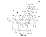
図1A、図1Bおよび図1Cは、後方脊椎手術のための1つの例示的な単椎弓根標的化システム100を示す図である。図1Aは、1つの例示的な使用シナリオにおける単椎弓根標的化システム100を示している。図1Bは、図1Aの使用シナリオで実施される単椎弓根標的化システム100を側面図でさらに詳細に示している。図1Cは、単椎弓根標的化システム100を椎弓根に固定するための例示的な位置を背面図で示している。図1A〜図1Cは一緒に見るのが最適である。
1A, 1B, and 1C illustrate one exemplary single
単椎弓根標的化システム100は、脊椎172の後側192から患者170の脊椎172の椎骨178の単一の椎弓根176に固定される。単椎弓根標的化システム100は、脊椎手術装置150を保持するように構成され、椎弓根176の近くの脊椎172での後方脊椎手術の実施において外科医180を補助する。一例では、脊椎手術装置150は、脊椎172の手術部位にアクセスするために患者170の組織を後退させるための開創器である。他の実施例では、脊椎手術装置150は、ロボット、ドリル、骨刀、キュレット、骨鉗子、やすり、器具/ケージアプライヤ、グラフトアプライヤ、または当技術分野で知られている他の脊椎手術器具などのような、介在する組織を後退させた後に脊椎172の手術の少なくとも一部を行うために使用される装置である。
The single
本明細書では、「外科医」は、1人または複数の人間、ロボットシステム、触覚技術を含むシステム、および/またはそれらの組み合わせを示し得る。 As used herein, a “surgeon” may refer to one or more humans, robotic systems, systems that include haptic technology, and / or combinations thereof.
図1Bに示すように、椎骨178(および脊椎172の他の椎骨179)は2つの椎弓根176を有する。各椎弓根176は、椎骨178の対応する椎間関節面164のほぼ前方にある。説明を明瞭にするために、図1Bおよび図1Cは、椎骨178および椎骨179のそれぞれの棘突起166、脊髄160(または髄嚢160)、神経根161および椎間板162を示す。図1Cは、横突起168をさらに示す。単椎弓根標的化システム100は、椎骨178の単一の椎弓根176にのみ固定される。椎弓根176は、脊椎手術装置150による手術を必要とする脊椎172の部分よりも下位であってもよいし上位であってもよい。本明細書の範囲から逸脱することなく、椎弓根176は、患者170の仙骨(図1Bには図示せず)の椎弓根であってもよい。
As shown in FIG. 1B, vertebra 178 (and
単椎弓根標的化システム100は、椎弓根176に固定されているので、患者の動きの悪影響は排除または低減される。これは、手術台などの外部システムに固定されるシステムに勝る大幅な改善である。単椎弓根標的化システム100は、標的手術部位が軌道の範囲に沿ってアクセスされ得るように、椎弓根176に対する脊椎手術装置150の配置のための6自由度を可能にする。特定の範囲の制限内で、単椎弓根標的化システム100は、椎弓根176に対して任意の位置および任意の向きに脊椎手術装置150を配置することができる。これにより、外科医180は、脊椎172の手術部位を標的とするための最適な軌道を選択することができる。さらに、一実施形態では、患者170の動きの存在下であっても、単椎弓根標的化システム100をロックして、この最適な軌道を維持することができる。他の実施形態では、単椎弓根標的化システム100のジョイントは、ジョイントを能動的にロックすることなく、安定した状態を維持するために動きに対する十分な抵抗を有する。概して、単椎弓根標的化システム100は、従来技術のシステムよりも嵩張りにくく、ハードウェアを少なくしながら、脊椎172の手術部位の正確かつ安定した標的設定を可能にする。
Because the single
単椎弓根標的化システム100は、例えば、腰椎または胸椎の低侵襲の後方脊椎手術によく適している。一実装形態では、約2センチメートル以下の小切開が椎弓根176に行われて単椎弓根標的化システム100を椎弓根176に固定し、例えば2〜4センチメートルのオーダーの他の小切開が脊椎172の手術部位に行われる。他の例では、椎弓根176と脊椎172の手術部位の両方にアクセスするために数センチメートルの単一切開が行われる。単椎弓根標的化システム100は、開創器を固定するために2つ以上の椎弓根を利用する従来の開腹手術および低侵襲手術の両方と比較して、危険性を少なくし、手術時間を短縮し、失血を減らし、軟組織の外傷を少なくし、患者170のより速い退院を促進することができる。
The single
単椎弓根標的化システム100は、ファスナ110を含む。使用時に、ファスナ110は、椎弓根176に固定される。ファスナ110は、ねじ、ピン、結合された錐およびタップ、経皮ねじ、椎弓根ねじ、または当該技術分野において既知の他の種類のファスナであってもよい。本明細書において、「椎弓根」ねじは、脊椎172に恒久的に(または少なくとも長期間)残され得るねじを示す。1レベル経椎間孔腰椎椎体間固定では、4つの椎弓根ねじが、脊椎部分に関連する4つのそれぞれの椎弓根に挿入される。脊椎部分を安定させるのを補助するために、2つの左椎弓根ねじを1つのロッドで接続し、2つの右椎弓根ねじを他のロッドで接続する。2レベル経椎間孔腰椎椎体間固定では、隣接する椎骨の左右の椎弓根に追加の椎弓根ねじの組が取り付けられる。2つの脊椎部分を安定させるために、3つの左椎弓根ねじを1つのロッドで接続し、3つの右椎弓根ねじを他のロッドで接続する。追加の各レベルの手術では、追加の椎骨の左右の椎弓根に追加の椎弓根ねじの組が取り付けられ、これらの追加の椎弓根ねじは、各側面のすべての椎弓根ねじを接続するために使用されるロッド構造物に含まれる。
Single
単椎弓根標的化システム100は、ジョイント構成要素122をさらに含み、ジョイント構成要素122は、脊椎手術装置150に含まれ、脊椎手術装置150に恒久的に結合されるか、または脊椎手術装置150に取り外し可能に結合されるジョイント構成要素152と嵌合するように構成される。ジョイント構成要素122および152は、3回転自由度を有するジョイントを形成するために嵌合するように構成される。一実施形態では、ジョイント構成要素122および152は、嵌合して球ジョイントを形成するように構成される。ジョイント構成要素122および152は、それぞれボールおよびソケット、またはそれぞれソケットおよびボールとすることができる。
The single
以下の図14A〜図14Cは、一実施形態を示しており、ジョイント構成要素152の実施形態が脊椎手術装置150の実施形態と取り外し可能に結合される。以下の図9は、一実施形態を示しており、ジョイント構成要素152の実施形態が、脊椎手術装置150の実施形態に含まれるか、または恒久的に結合される。ジョイント構成要素152が脊椎手術装置150とどのように結合されているか(または含まれているか)にかかわらず、ジョイント構成要素152と脊椎手術装置150の操作部との間に接続アームが存在してもよい。例えば、この接続アームは、脊椎手術装置150の位置決めのフレキシビリティを改善し、標的手術部位(例えば、図14A〜図14C、図29A〜図29C、図42Aおよび図42Bを参照)への画像化アクセスを改善するように角度が付けられている。この開示を通して、脊椎手術装置150の実施形態に恒久的に結合された(または含まれる)ジョイント構成要素152の実施形態は、脊椎手術装置150の実施形態に取り外し可能に結合されたジョイント構成要素152の実施形態に置き換えられてもよいし、その逆も同様であることが理解される。
14A-14C below illustrates one embodiment, in which an embodiment of a
本明細書では、「ジョイント構成要素」とは、2つのジョイント構成要素が接続されることによって、2つのジョイント構成要素が互いに対して移動することを可能にするジョイントを形成することができるように、ジョイントの一部を指す。例えば、2つのジョイント構成要素は、互いに嵌合して球ジョイントを形成するボールおよびソケットであってもよい。他の例では、2つのジョイント構成要素は、互いに嵌合して3回転自由度を有するジョイントを形成する突起部およびレセプタクルである。さらに他の例では、2つのジョイント構成要素は、互いに嵌合して円筒状ジョイントを形成するシリンダおよび貫通孔を有する要素である。さらなる例では、1つのジョイント構成要素が他のジョイント構成要素にフィットして入れ子式ジョイントを形成する。ジョイントを形成するための2つのジョイント構成要素間の結合は、例えば、機械的および/または磁気的であり、2つのジョイント構成要素間に摩擦を有するように構成されてもよい。さらに、「ジョイント」は、2つのジョイント構成要素を接続することによって形成される必要はない。一例では、ジョイントは、可撓性材料の2つの異なる部分に取り付けられた2つの要素が互いに対して動くことができるように、可撓性材料であってもよい。本明細書では、「球ジョイント」とは、3回転自由度を有し、製造公差に関連するものを超える並進自由度を持たないジョイントを示す。球ジョイントは、例えば、互いに嵌合する突起部およびレセプタクル、または互いに嵌合するボールとソケットであり、ボールは完全なボールである必要はないがボールの一部を含む。 As used herein, “joint component” means that the two joint components can be connected to form a joint that allows the two joint components to move relative to each other. , Refers to a part of the joint. For example, the two joint components may be a ball and a socket that fit together to form a ball joint. In another example, the two joint components are protrusions and receptacles that fit together to form a joint with three degrees of freedom of rotation. In yet another example, the two joint components are elements having a cylinder and a through hole that fit together to form a cylindrical joint. In a further example, one joint component fits into another joint component to form a nested joint. The coupling between two joint components to form a joint may be, for example, mechanical and / or magnetic and configured to have friction between the two joint components. Further, a “joint” need not be formed by connecting two joint components. In one example, the joint may be a flexible material so that two elements attached to two different portions of the flexible material can move relative to each other. As used herein, “ball joint” refers to a joint that has three rotational degrees of freedom and does not have translational degrees of freedom that exceed those associated with manufacturing tolerances. A ball joint is, for example, a protrusion and receptacle that fit together, or a ball and socket that fit together, and the ball need not be a complete ball, but includes a portion of the ball.
単椎弓根標的化システム100は、ジョイント構成要素122および152によって形成されたジョイントと協働して、ファスナ110に対する脊椎手術装置150の3並進自由度および3回転自由度を提供する複数のコネクタ130およびジョイント120を含む。したがって、ファスナ110が椎弓根176に固定され、脊椎手術装置150がジョイント構成要素122に接続されている場合には、単椎弓根標的化システム100は、椎弓根176に対する脊椎手術装置150の3並進自由度および3回転自由度を可能にしながら、脊椎手術装置150を椎弓根176に固定する。
The single
図1Bに示された例示の実施形態では、単椎弓根標的化システム100は、2つのジョイント120と2つのコネクタ130とを含む。第1のコネクタ130は、第1のジョイント120を介してファスナ110に接続するように構成され、第2のコネクタ130は、第2のジョイント120を介して第1のコネクタ130と嵌合するように構成される。この実施形態の一例では、ファスナ110と第1のコネクタ130との間のジョイント120は3回転自由度を有し、第1および第2のコネクタ130の間のジョイント120は並進自由度を有し、ジョイント構成要素122および152によって形成されるジョイントは3回転自由度を有する。
In the exemplary embodiment shown in FIG. 1B, the single
本開示は、図1Bに示す特定の実施形態に限定されないことが理解される。例えば、単椎弓根標的化システム100は、異なる数のジョイント120およびコネクタ130を含み、椎弓根176に対する3並進自由度および3回転自由度を脊椎手術装置150に提供することができる。
It is understood that the present disclosure is not limited to the specific embodiment shown in FIG. 1B. For example, the single
図2Aは、単椎弓根標的化システム100のより一般的な実施形態を示すブロック図である。単椎弓根標的化システム100は、ファスナ110およびマニピュレータ210を含む。マニピュレータ210は、ジョイント構成要素122、複数のコネクタ130のうちの1つ、および1つまたは複数の追加のジョイント構成要素222を含む。任意選択で、ファスナ110は、ジョイント構成要素222と嵌合してファスナ110とマニピュレータ210との間の結合部にジョイントを形成するように構成されたジョイント構成要素224を含む。図2Aには示されていないが、コネクタ130は、本明細書の範囲から逸脱することなく、ジョイント構成要素122および222を実装することができる。
FIG. 2A is a block diagram illustrating a more general embodiment of the single
図1A〜図1Cを参照して説明したように、ファスナ110は、椎弓根176に固定されるように構成され、ジョイント構成要素122は、脊椎手術装置150のジョイント構成要素152と接合して手術部位270を標的とするように構成される。特定の実施形態では、単椎弓根標的化システム100は、脊椎手術装置150の少なくとも一部を含む。例えば、単椎弓根標的化システム100は、ジョイント構成要素152を含むことができる。
As described with reference to FIGS. 1A-1C, the
単椎弓根標的化システム100は、組み立てられた形態で、またはユーザによって実行される少なくともいくつかの組み立てを必要とする形態で、ユーザに提供されてもよい。例えば、単椎弓根標的化システム100は、別個のファスナ110および別個のコネクタ130としてユーザに提供されてもよく、コネクタ130は、ジョイント構成要素122および222を実装する。その後、ユーザはこれらの別々の要素を組み立てる。さらに、ファスナ110は、本明細書の範囲から逸脱することなく、ファスナ110を形成するためにユーザによって組み立てられる2つ以上の別個の部品としてユーザに提供されてもよい。例えば、ファスナ110は、ねじ部材および非ねじ部材として提供されてもよく、ねじ部材は、コネクタ130と接続するように構成される。
The single
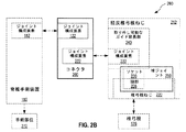
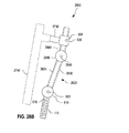
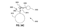
図2Bは、経皮椎弓根ねじ212と結合して1つの例示的な単椎弓根標的化システム290を形成するように構成された例示的なコネクタ200を示すブロック図である。単椎弓根標的化システム290は、単椎弓根標的化システム100の実施形態である。単椎弓根標的化システム290は、脊椎手術装置150の少なくとも一部をさらに含み得る。
FIG. 2B is a block diagram illustrating an
経皮椎弓根ねじ212は、第三者ベンダーによって製造された市販の経皮椎弓根ねじ、またはコネクタ200とともに供給されるカスタムメード品であってもよい。経皮椎弓根ねじ212として実装するのに適した経皮椎弓根ねじを供給する例示的なベンダーには、Stryker、DePuy Synthes、NuVasive、Globus、K2 Medical、Medtronic、Biomet、およびZimmer Spineが含まれるが、これらに限定されない。経皮椎弓根ねじ212は、(a)椎弓根176にねじ込むための椎弓根ねじ220と、(b)椎弓根ねじ220の頭部226を有する球ジョイント250を形成する(当該技術分野で知られている「チューリップ」のような)ソケット230と、(c)ソケット230の取り外し可能なガイド延長部240とを含む。取り外し可能なガイド延長部240は、椎弓根ねじ220が椎弓根部176に固定されたときに患者170の外側に延在し、一般にツールまたは他のハードウェアを椎弓根ねじ220、ソケット230、または椎弓根176付近の位置に案内するように働く。取り外し可能なガイド延長部240は、取り外し可能および再挿入可能の両方であってもよく、あるいは、不可逆的な方法でのみ取り外し可能であり、したがって再挿入可能でなくてもよい。必要でなくなったときに、取り外し可能なガイド延長部240は、例えば取り外し可能なガイド延長部240とソケット230との間の比較的脆弱な接続を断つことによって、取り外し可能なガイド延長部240をソケット230から外すことによって、または取り外し可能なガイド延長部240とソケット230との間の圧力嵌め接続を切り離すことによって、ソケット230から取り外すことができる。椎弓根ねじ220はファスナ110の実施形態であり、頭部226はジョイント構成要素224の実施形態であり、ソケット230はジョイント構成要素222の実施形態であり、取り外し可能なガイド延長部240はジョイント構成要素222を実装するコネクタ130の実施形態である。
The
本明細書では、「経皮椎弓根ねじ」という用語は、患者170に経皮的に挿入される装置に限定されない。本開示を通じて、「経皮椎弓根ねじ」は、例えば開腹手術で一般的に行われるように、患者170に経皮的または非経皮的に挿入され得る。
As used herein, the term “percutaneous pedicle screw” is not limited to devices that are inserted percutaneously into the
コネクタ200は、(a)ジョイント構成要素152と嵌合して3回転自由度を有するジョイントを形成するように構成されたジョイント構成要素122と、(B)取り外し可能なガイド延長部240のジョイント構成要素222と嵌合して少なくとも並進自由度を有するジョイントを形成するように構成されたジョイント構成要素222とを実装する。したがって、コネクタ200は、経皮椎弓根ねじ212が椎弓根176に固定されたときに、経皮椎弓根ねじ212およびジョイント構成要素152と協働して、椎弓根176に対する3並進自由度および3回転自由度を脊椎手術装置150に提供することができる。コネクタ200は、取り外し可能なガイド延長部240およびソケット230と協働して、マニピュレータ210の実施形態を形成する。
The
コネクタ200は、単椎弓根標的化システム290の経皮椎弓根ねじ212の多目的使用を容易にする。単椎弓根標的化システム290を利用して脊椎手術装置150を標的手術部位270に位置決めした後、外科医180は、例えば、経皮椎弓根ねじ212からコネクタ200を取り外した後に、椎弓根ねじ220を椎弓根176の所定の位置に残しながら、取り外し可能なガイド延長部240をソケット230から取り外すことができる。椎弓根ねじ220は、他の目的、例えばロッドを椎弓根ねじ220および脊椎172の同じ側に隣接する椎弓根に固定された他の椎弓根ねじに取り付けることによって脊椎部分を安定させるために使用することができる。
The
一実施形態では、コネクタ200のジョイント構成要素122は、ジョイント構成要素152と嵌合して球形ジョイントを形成する。一実施形態では、コネクタ200のジョイント構成要素222は、ソケット230から可変距離で経皮椎弓根ねじ212のジョイント構成要素222に取り付けることができる。任意選択で、コネクタ200のジョイント構成要素222と経皮椎弓根ねじ212との間に形成されたジョイントは、回転自由度をさらに有し、例えば円筒形ジョイントである。
In one embodiment, the
本明細書の範囲から逸脱することなく、コネクタ200は、コネクタ200のジョイント構成要素222が、異なるサイズまたは形状のジョイント構成要素222を有する1つまたは複数のそれぞれの経皮椎弓根ねじに結合され得るように、1つまたは複数のアダプタとともに供給され得る。
Without departing from the scope herein, the
図56〜図59を参照して以下にさらに詳細に説明するように、単椎弓根標的化システム100は、それぞれが単椎弓根標的化システム100と同じ機能性を有するが、脊椎172の異なる構造または患者170の骨盤に固定され得る、脊椎固定式標的化システムに容易に拡張される。このような脊椎固定式標的化システムは、患者170の頸椎、胸椎、および/または腰椎の後方脊椎手術において使用され得る。
As described in more detail below with reference to FIGS. 56-59, the single
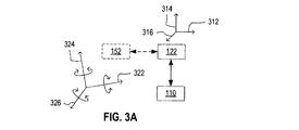
図3Aおよび3Bは、マニピュレータ210およびマニピュレータ210に接続された脊椎手術装置150の例示的な動作を示す。図3Aおよび図3Bは、一緒に見るのが最適である。マニピュレータ210は、少なくとも3つの直交する方向312、314、および316、または交互に3次元空間に広がる少なくとも3つの他の方向に、ファスナ110に対してジョイント構成要素122を並進させることができる。これらの並進自由度は、ファスナ110に対する脊椎手術装置150の位置310の3並進自由度をもたらす。図3Bにおいて脊椎手術装置150の一端に示しているが、位置310は、脊椎手術装置150の中心の位置のような脊椎手術装置150の異なる部分を基準とすることができる。
FIGS. 3A and 3B illustrate an exemplary operation of manipulator 210 and
脊椎手術装置150のジョイント構成要素152がジョイント構成要素122に接続されるとき、ジョイント構成要素152、したがって脊椎手術装置150は、少なくとも3つの直交軸322、324、326、または交互に3次元空間に広がる少なくとも3つの他の軸に対して回転させることができる。一例では、軸322、324、326はそれぞれ方向312、314、316に平行である。他の例では、軸322、324、326の少なくとも1つは、方向312、314、316のいずれか1つに平行ではない。これらの回転自由度は、ファスナ110に対する脊椎手術装置150の向き350の3回転自由度をもたらす。図3Bにおいて脊椎手術装置150の長手方向軸を示したが、向き350は、脊椎手術装置150の操作部分に関連する軸のような、脊椎手術装置150の異なる軸を基準とすることができる。
When the
本明細書の範囲から逸脱することなく、図3Aおよび図3Bの線図は、単椎弓根標的化システム290にも適用され、この場合、図3Aおよび図3Bのファスナ110およびジョイント構成要素122は、それぞれ、コネクタ200の椎弓根ねじ220およびジョイント構成要素122を示す。
Without departing from the scope herein, the diagrams of FIGS. 3A and 3B also apply to the single
図4Aは、1つまたは複数のコネクタに実装されたジョイント構成要素を有するマニピュレータ410を含む、後方脊椎手術のための1つの例示的な単椎弓根標的化システム400を示す。単椎弓根標的化システム400は単椎弓根標的化システム100の実施形態であり、マニピュレータ410はマニピュレータ210の実施形態である。
FIG. 4A shows one exemplary single
単椎弓根標的化システム400は、ファスナ110およびマニピュレータ410を含む。ファスナ110は、ジョイント構成要素224を含む。マニピュレータ410は、ジョイント構成要素422およびジョイント構成要素122を実装する1つのコネクタ440を含む。ジョイント構成要素122は、ジョイント構成要素152と嵌合するように構成され、マニピュレータ410と脊椎手術装置150との間のジョイント412を形成する。ジョイント412は、3回転自由度を有し、例えば、球ジョイントである。ジョイント構成要素422は、ジョイント構成要素222の実施形態であり、コネクタ440は、コネクタ130の実施形態である。
Single
一実施形態では、マニピュレータ410は、追加のコネクタ431を含む。追加のコネクタ431は、コネクタ130の実施形態であり、ジョイント構成要素422および224とそれぞれ嵌合するための2つのジョイント構成要素432を含み、ジョイント420および430をそれぞれ形成する。
In one embodiment, the manipulator 410 includes an
他の実施形態では、マニピュレータ410は、2つの追加のコネクタ431を含む。この実施形態では、第1の追加のコネクタ431のジョイント構成要素432は、ジョイント構成要素422と嵌合して第1のジョイント420を形成するように構成され、最後の追加のコネクタ431のジョイント構成要素432は、ジョイント構成要素224と嵌合して、ジョイント430を形成するように構成され、第1の追加のコネクタ431のジョイント構成要素432は、最後の追加のコネクタ431のジョイント構成要素432と嵌合して第2のジョイント420を形成するように構成される。なお、図4Aは、2つの追加のコネクタ431のみを示しているが、マニピュレータ410は、本明細書の範囲から逸脱することなく、複数の追加のコネクタ431のうちの3つを含むことができる。例えば、追加の中間ジョイント420を形成するために、2つを超える追加のコネクタ431を第1のコネクタ431と最後のコネクタ431との間に挿入する(それぞれコネクタ440とファスナ110に接続する)ことができる。
In other embodiments, the manipulator 410 includes two
さらに他の実施形態では、マニピュレータ410は、追加のコネクタ431を含まず、ジョイント構成要素422は、ジョイント構成要素224と嵌合してジョイント430を形成するように構成される。
In yet other embodiments, manipulator 410 does not include
任意選択で、マニピュレータ410は、所望の構成でジョイント412をロックするように係合することができるロック装置414を含む。マニピュレータ410はまた、所望の構成でジョイント430をロックするように係合することができるロック装置434も含むことができる。各ジョイント420について、マニピュレータ410は、所望の構成でそれぞれのジョイント420をロックするように係合することができるロック装置424を含むことができる。ロック装置414、424、および434のそれぞれは、例えばファスナである。本明細書の範囲から逸脱することなく、ロック装置414、424、および434のうちの1つまたは複数は、ジョイント412、420、および/または430の代わりにコネクタ440および431のうちの1つまたは複数に作用して、コネクタ440および431のうちの1つまたは複数の位置をロックするように構成されてもよい。
Optionally, manipulator 410 includes a
単椎弓根標的化システム400は、組み立てられた形態で、またはユーザによって実行される少なくともいくつかの組み立てを必要とする形態で、ユーザに提供されてもよい。例えば、単椎弓根標的化システム400は、別個のファスナ110、別個のコネクタ130、および任意選択で、ユーザによって組み立てられる別個のコネクタ431としてユーザに提供されてもよい。さらに、ファスナ110は、本明細書の範囲から逸脱することなく、ファスナ110を形成するためにユーザによって組み立てられる2つ以上の別個の部品としてユーザに提供されてもよい。例えば、ファスナ110は、ねじ部材および非ねじ部材として提供されてもよく、ねじ部材は、椎弓根176に固定されるように構成され、非ねじ部材は、ジョイント構成要素224を含む。単椎弓根標的化システム400は、脊椎手術装置150の少なくとも一部を含み得る。
The single
図56〜図59を参照して以下にさらに詳細に説明するように、単椎弓根標的化システム400は、それぞれが単椎弓根標的化システム400と同じ機能性を有するが、脊椎172の異なる構造または患者170の骨盤に固定され得る、脊椎固定式標的化システムに容易に拡張される。このような脊椎固定式標的化システムは、患者170の頸椎、胸椎、および/または腰椎の後方脊椎手術において使用され得る。
As described in more detail below with reference to FIGS. 56-59, the single
図4Bは、経皮椎弓根ねじ212も利用する1つの例示的な単椎弓根標的化システム450において実装されるコネクタ200を示す図である。単椎弓根標的化システム450は、単椎弓根標的化システム290および400の実施形態である。単椎弓根標的化システム450は、コネクタ200および経皮椎弓根ねじ212を含み、脊椎手術装置150の少なくとも一部をさらに含み得る。
FIG. 4B shows a
単椎弓根標的化システム450において、ジョイント構成要素122は、ジョイント構成要素152と嵌合してジョイント412を形成するように構成される。同様に、コネクタ200のジョイント構成要素222は、取り外し可能なガイド延長部240のジョイント構成要素222と嵌合してジョイント420を形成するように構成される。特定の実施形態では、コネクタ200は、ジョイント412および420をロックするように構成されたロック装置414および424にそれぞれ結合するように構成される。一例では、ロック装置414および424の一方または両方がコネクタ200に含まれるか、またはコネクタ200とともにユーザに供給される。
In the single
単椎弓根標的化システム450は、ロック装置414、424、およびロック装置434のうちの1つまたは複数を含むことができ、ロック装置434は、球ジョイント250をロックするように構成される。球ジョイント250は、ジョイント430の実施形態である。
The single
図4Cは、経皮椎弓根ねじ212と協働して1つの例示的な単椎弓根標的化システム490を形成するように構成された1つの例示的なコネクタ460を示す図である。コネクタ460は、少なくとも1つの追加のジョイントをさらに含むコネクタ200の実施形態である。単椎弓根標的化システム490は、単椎弓根標的化システム400および450の実施形態である。
FIG. 4C illustrates one
コネクタ460は、サブコネクタ462、464と、任意選択で1つまたは複数の追加のサブコネクタ466とを含む。説明を分かりやすくするために、ただ1つの追加のサブコネクタ466が図4Cに示されている。サブコネクタ462は、コネクタ440の実施形態である。サブコネクタ464および466のそれぞれは、コネクタ431の実施形態である。サブコネクタ462は、ジョイント構成要素122およびジョイント構成要素472を含む。サブコネクタ464は、ジョイント構成要素472と、図4Bを参照して説明したように経皮椎弓根ねじ212のジョイント構成要素222と嵌合してジョイント420を形成するように構成されたジョイント構成要素222とを含む。任意選択によるサブコネクタ466のそれぞれは、コネクタ460に含まれる2つの他のサブコネクタの2つのジョイント構成要素472と嵌合して2つのそれぞれのジョイント420を形成するように構成された2つのジョイント構成要素472を含む。ジョイント構成要素472のそれぞれは、ジョイント構成要素432の実施形態である。ジョイント420のそれぞれは、それぞれのロック装置424と結合されてもよい。コネクタ460は、そのようなロック装置424のそれぞれを含むことができ、または、このようなロック装置424のそれぞれとともにユーザに供給されてもよい。
図5Aは、後方脊椎手術のための1つの例示的な単椎弓根標的化方法500を示す図である。方法500は、患者170の椎弓根176に単椎弓根標的化システムを固定するステップと、患者170の後方脊椎手術において単椎弓根標的化システムを使用するステップとを含む。単椎弓根標的化システムは、患者170の椎弓根176に対して3並進自由度および3回転自由度を脊椎手術装置150に許容しながら、脊椎手術装置150を保持するように構成される。方法500は、単椎弓根標的化システム100を設置するために使用されてもよく、後方脊椎手術を行うために単椎弓根標的化システム100を適用してもよい。
FIG. 5A illustrates one exemplary single
ステップ510において、ファスナが脊椎部分の1つの椎弓根に固定される。ステップ510は、ドリル、タップ、ジャムシディ針、および/またはガイドワイヤなど、当該技術分野において既知の装置を利用することができる。ファスナは、カニューレ式であってもカニューレ式でなくてもよい。一例では、ステップ510は、カニューレファスナを椎弓根176内の位置に案内するためのガイドワイヤを利用する。一実施形態において、ステップ510は、単椎弓根標的化システムのための軌道テンプレートを生成するステップ512を含む。例えば、ステップ512は、軌道テンプレートを生成するために蛍光透視法および/または他のナビゲーションツールを用いて椎弓根176を配置するステップを含むことができる。この軌道テンプレートは、ステップ510において、椎弓根176へのファスナの最適軌道を選択するために使用される。軌道テンプレートは、少なくとも部分的に、脊椎手術装置150の予想される最適軌道と、ファスナの軌道を脊椎手術装置150の軌道に関連付ける単椎弓根標的化システムの幾何学的特性とに基づいて生成される。ステップ510の一例では、外科医180はファスナ110を椎弓根176に固定する。外科医180またはコンピュータシステムは、脊椎手術装置150をファスナ110に固定するために使用する際に、脊椎手術装置150の予想される最適軌道および単椎弓根標的化システム100の幾何学的特性に少なくとも部分的に基づき得るファスナ110のための軌道テンプレートを生成することができる。
At step 510, the fastener is secured to one pedicle of the spinal portion. Step 510 may utilize devices known in the art such as drills, taps, jamsidi needles, and / or guidewires. The fasteners may or may not be cannulated. In one example, step 510 utilizes a guide wire to guide the cannula fastener to a location within the
一実施形態では、ファスナ110を含む単椎弓根標的化システムは予め組み立てられ、ステップ510の前に脊椎手術装置150に接続される。他の実施形態では、方法500は、ファスナが固定される椎弓根176に対する脊椎手術装置150の3並進自由度および3回転自由度を可能にするマニピュレータを介して、脊椎手術装置150をステップ510のファスナに接続するステップ520を含む。ステップ520の一例では、外科医180は、この例ではファスナ110に予め接続されているマニピュレータ210に脊椎手術装置150を接続する。ステップ520の他の例では、外科医180はマニピュレータ210をファスナ110に接続し、脊椎手術装置150をマニピュレータ210に接続する。ステップ520のさらに他の例では、外科医180は、マニピュレータ210の一部を、ファスナ110に予め接続されたマニピュレータ210の他の部分に接続し、脊椎手術装置150をマニピュレータ210に接続する。
In one embodiment, a single pedicle targeting system that includes
ステップ530は、単椎弓根標的化システムの脊椎手術装置150およびマニピュレータを操作して、患者170の手術部位270を脊椎手術装置150により標的とし、脊椎手術装置150は、マニピュレータおよびステップ510のファスナを介して椎弓根176に固定される。一実施形態では、ステップ530は、椎弓根176に対する脊椎手術装置150の少なくとも1つの並進自由度を操作するステップ532を含む。他の実施形態では、ステップ530は、椎弓根176に対する脊椎手術装置150の少なくとも1つの回転自由度を操作するステップ534を含む。ステップ530の一例では、外科医180は、マニピュレータ210と、マニピュレータ210およびファスナ110を介して椎弓根176に固定された脊椎手術装置150とを操作して、手術部位270を脊椎手術装置150により標的に定める。外科医180は、椎弓根176に対する脊椎手術装置150の1、2、または3並進自由度および/または1、2、または3回転自由度を操作することができる。
Step 530 operates the
一実施形態では、方法500は、ステップ530で使用されるマニピュレータおよび/または脊椎手術装置150の少なくとも一部分の位置および向きをロックして、椎弓根176に対する脊椎手術装置150の動きを少なくとも制限するステップ540を含む。ステップ540の一例では、外科医180は、脊椎手術装置150の動きを少なくとも制限するように、ロック装置414、424、および434のうちの1つまたは複数を係合して、ジョイント412、420、および430のうちの1つまたは複数を所望の構成にそれぞれロックする。例えば、外科医180は、実装された各ロック装置を係合して、椎弓根176に対する脊椎手術装置150の位置および向きを完全にロックすることができる。必要に応じて、方法500は、ステップ540からステップ530に戻って、脊椎手術装置150の位置および/または向きを調整することができる。
In one embodiment, the
任意選択で、方法500は、ステップ530で位置決めされた脊椎手術装置150を使用して外科処置を行うステップ550をさらに含む。ステップ550の一例では、脊椎手術装置150は、患者170の組織を後退させて手術部位270へのアクセスを提供する開創器である。ステップ550の他の例では、脊椎手術装置150は、患者170の脊椎172に対して操作するためのツール、例えば患者170から組織を除去する、または、ハードウェアまたはインプラントを患者170に挿入するために使用されるツールである。必要に応じて、方法500は、ステップ550からステップ530に戻って、脊椎手術装置150の位置および/または向きを調整し、任意選択でステップ540を実行して脊椎手術装置150の動きを再度制限することができる。
Optionally,
任意選択によるステップ560において、方法500は、脊椎手術装置150を取り除く。ステップ560の一例では、外科医180は、単椎弓根標的化システム100から脊椎手術装置150を取り除く。必要に応じて、方法500は、異なる脊椎手術装置150を椎弓根176に固定するように、ステップ560からステップ520に戻って異なる脊椎手術装置150を単椎弓根標的化システム100に接続することができる。ステップ560は、マニピュレータまたはマニピュレータの少なくとも一部が不要になったときにそれを取り除くステップを含むこともできる。ステップ560のそのような一例では、外科医180はマニピュレータ210をファスナ110から取り外す。ステップ560の他のそのような例では、外科医180は、ファスナ110のその後の除去を可能にするのに十分なだけマニピュレータ210の一部を取り除く。さらに、ステップ560は、椎弓根176からファスナを引き出すステップを含み得る。ステップ560のこのような一例において、外科医180は、例えば脊椎手術装置150を取り外した後に、および任意選択でマニピュレータ210の少なくとも一部を取り外した後に、ファスナ110を椎弓根176から引き出す。
In
一実施形態では、ステップ560は、ファスナ、および任意選択でマニピュレータの少なくとも一部を取り除くためのガイドワイヤを利用するステップ562を含む。ステップ560がステップ562を実施するとき、ガイドワイヤがファスナのカニューレ挿入部を通してファスナに挿入され、ファスナがガイドワイヤに沿って取り除かれる。ガイドワイヤは、ファスナとマニピュレータの少なくとも一部の両方がガイドワイヤに沿って取り除かれるように、マニピュレータの少なくとも一部を通過してもよい。ステップ562とともに実施されるステップ560の一例では、外科医180は、ガイドワイヤをファスナ110のカニューレ挿入部に挿入し、ガイドワイヤに沿って椎弓根部176からファスナ110を引き出す。他の実施形態では、ステップ560は、ガイドワイヤを使用せずにファスナを取り除く。
In one embodiment,
ステップ562を含む方法500の実施形態は、ガイドワイヤに沿って椎弓根ねじを椎弓根176に挿入するステップ570をさらに含むことができる。これにより、外科医は、椎弓根ねじを挿入する際に、ステップ510で挿入されたファスナの既存の軌道、および椎弓根176内のこのファスナによって作られた穴を利用することができる。椎弓根ねじは、3.5〜7ミリメートルの範囲の直径を有することができる。一実施形態では、椎弓根ねじは、椎弓根ねじと椎弓根176との間の接触が、ステップ510で挿入されたファスナによってもたらされる椎弓根176の損傷によって損なわれないように、ステップ510で挿入されたファスナよりも大きな直径を有する。一例では、ファスナ110は、約4ミリメートルの外径を有し、一方、椎弓根ねじは、約6ミリメートルの外径を有する。他の例では、椎弓根ねじの直径は、ファスナ110の直径により約1〜3ミリメートルだけ大きい。ステップ562を含まない方法500の実施形態は、ガイドワイヤを使用せずにステップ570を実行することができる。
Embodiments of
任意選択で、方法500は、ステップ560の後またはステップ570の後に脊椎手術処置を完了するステップ580を含む。ステップ580は、当技術分野で公知の方法を利用することができる。
Optionally,
方法500の1つの実装形態は、単椎弓根標的化システム450を利用する。この実装形態では、ステップ510は、任意選択でステップ512で決定された軌道に沿って、経皮椎弓根ねじ212を椎弓根176に固定するステップを含む。ステップ520において、脊椎手術装置150は、コネクタ200を介して取り外し可能なガイド部240に取り付けられる。ステップ530は、球ジョイント250、ジョイント420、およびジョイント412の少なくともいくつかの自由度を操作して、脊椎手術装置150により手術部位270を標的にする。実施される場合には、ステップ540は、脊椎手術装置150を使用してステップ550において外科処置を実施する前に、ロック装置414、424、434のうちの1つまたは複数を利用して単椎弓根標的化システム450の少なくとも一部を所望の構成にロックする。実施される場合には、ステップ560は、経皮椎弓根ねじ212を残しながら、脊椎手術装置150およびコネクタ200を取り除くステップを含む。この実装形態は、ステップ570を必要としない。ステップ580において、経皮椎弓根ねじ212は、脊椎手術処置の他の目的を果たすことができる。例えば、ロッドは、取り外し可能なガイド部240を介して患者170に挿入され、ソケット230および脊椎172の同じ側の隣接する椎弓根に固定された経皮椎弓根ねじの同様のソケットに配置され、ソケット230および隣接する椎弓根に固定された同様のソケットに固定され得る。方法500のこの実装形態は、このファスナを椎弓根ねじに置き換えるために非椎弓根ねじファスナを取り除く必要性を排除し、したがってワークフローを単純化し、椎弓根176への起こり得る損傷を最小にする。
One implementation of the
本明細書の範囲から逸脱することなく、方法500(ステップ570なし)は、患者170の頸椎、胸椎、および/または腰椎の後方脊椎手術を行うために、椎弓根176とは異なる脊椎172の構造または患者170の骨盤に固定された脊椎固定式標的化システムを利用することができる。このような脊椎固定式標的化システムは、以下の図56〜59を参照してさらに説明される。
Without departing from the scope of the present description, the method 500 (without step 570) may be used to perform a vertebral 172 different from the
図5Bは、後方脊椎手術のための他の例示的な単椎弓根標的化方法501を示す図である。方法501は、任意選択によるステップ520およびステップ530がそれぞれステップ521および531に置き換えられている点を除いて、方法500と同様である。
FIG. 5B illustrates another exemplary single
ステップ521において、脊椎手術装置150は、ファスナに取り付けられたマニピュレータを介して椎弓根176に固定される。ステップ521の一例では、外科医180は、この例ではファスナ110に予め接続されているマニピュレータ210に脊椎手術装置150を接続する。ステップ521の他の例では、外科医180はマニピュレータ210をファスナ110に接続し、脊椎手術装置150をマニピュレータ210に接続する。ステップ521のさらに他の例では、外科医180は、マニピュレータ210の一部を、ファスナ110に予め接続されたマニピュレータ210の他の部分に接続し、脊椎手術装置150をマニピュレータ210に接続する。ステップ521のさらなる例では、外科医180はコネクタ200を使用して脊椎手術装置150を経皮椎弓根ねじ212に接続する。
In
ステップ531は、マニピュレータを調整して、椎弓根176に対する3並進自由度および3回転自由度を用いて脊椎手術装置150の位置および向きを規定し、患者170の手術部位270を脊椎手術装置150により標的に定める。ステップ531は、ステップ532および534の一方または両方を含むことができる。外科医180は、椎弓根176に対する脊椎手術装置150の1、2、または3並進自由度および/または1、2、または3回転自由度を操作することができる。ステップ531の一例では、外科医180は、マニピュレータ210およびファスナ110を介して椎弓根176に固定されたマニピュレータ210および脊椎手術装置150を操作し、手術部位270を脊椎手術装置150により標的に定める。ステップ531の他の例では、外科医180は、単椎弓根標的化システム450の球ジョイント250、ジョイント412およびジョイント420の1つまたは複数の自由度を操作し、コネクタ200および経皮椎弓根ねじ212を介して椎弓根176に固定された脊椎手術装置150により手術部位270を標的に定める。
Step 531 adjusts the manipulator to define the position and orientation of the
本明細書の範囲から逸脱することなく、方法501(ステップ570なし)は、患者170の頸椎、胸椎、および/または腰椎の後方脊椎手術を行うために、椎弓根176とは異なる脊椎172の構造または患者170の骨盤に固定された脊椎固定式標的化システムを利用することができる。このような脊椎固定式標的化システムは、以下の図56〜59を参照してさらに説明される。
Without departing from the scope herein, the method 501 (without step 570) may be used to perform a vertebral, thoracic, and / or lumbar spine posterior spine surgery on the
図5Cは、後方脊椎手術のためのさらに他の例示的な単椎弓根標的化方法502を示す図である。方法502は、ステップ521および531がステップ515および533に置き換えられている点を除いて、方法501と同様である。
FIG. 5C illustrates yet another exemplary single
ステップ515において、外科医180は、手術部位270を標的とするのに適した位置および向きに脊椎手術装置150を配置する。ステップ515は、マニピュレータを介して脊椎手術装置150を椎弓根176に固定する前に実行される。
In
ステップ533において、外科医180は、ステップ515で得られた脊椎手術装置150の位置および向きを維持または少なくともほぼ維持しながら、マニピュレータを組み立てて調整し、脊椎手術装置150を椎弓根176に固定する。ステップ533は、ステップ535および537を含むことができる。ステップ535において、外科医180は、並進自由度を有するマニピュレータの第2のジョイントを組み立てる。ステップ535の一例では、外科医180は、マニピュレータ410のジョイント420を組み立てる。ステップ535の他の例では、外科医180は、単椎弓根標的化システム450のジョイント420を組み立てる。ステップ537において、外科医180は、脊椎手術装置を椎弓根に固定するように、第3のジョイントを組み立てて脊椎手術装置をマニピュレータに結合するために、(a)第2のジョイントと椎弓根176との間に位置する第1のジョイント、および(b)第2のジョイントを操作する。第1のジョイントは、椎弓根に対して固定された位置および3回転自由度を有し、第3のジョイントは、3回転自由度を有する。
In step 533, the
本明細書の範囲から逸脱することなく、方法502は、ステップ533の後に脊椎手術装置150の位置および/または向きを調整するためのマニピュレータのさらなる操作を含むことができる。
Without departing from the scope herein, the
本明細書の範囲から逸脱することなく、方法502(ステップ570なし)は、患者170の頸椎、胸椎、および/または腰椎の後方脊椎手術を行うために、椎弓根176とは異なる脊椎172の構造または患者170の骨盤に固定された脊椎固定式標的化システムを利用することができる。このような脊椎固定式標的化システムは、以下の図56〜59を参照してさらに説明される。
Without departing from the scope of this specification, the method 502 (without step 570) may be used to perform a vertebral 172 different from the
図5Dは、経皮椎弓根ねじ212を介して脊椎手術装置150を椎弓根176に固定するためにコネクタ200を使用する、後方脊椎手術のための例示的な単椎弓根標的化方法503を示す図である。方法503は、方法500、501、および502のそれぞれの一部の実施形態である。
FIG. 5D illustrates an exemplary single pedicle targeting method for posterior spine surgery using the
任意のステップ511において、外科医180は、経皮椎弓根ねじ212を椎弓根176に固定する。ステップ511は、経皮椎弓根ねじ212用の軌道テンプレートを生成するステップ513を含むことができる。ステップ513は、経皮椎弓根ねじ212に適用されるステップ512である。ステップ511は、ステップ510の実施形態である。
In optional step 511, the
ステップ523において、外科医180は、脊椎手術装置150を経皮椎弓根ねじ212にコネクタ200を介して結合して、脊椎手術装置150を椎弓根176に固定する。ステップ523は、ステップ525および527を含む。ステップ525において、外科医180は、コネクタ200を経皮椎弓根ねじ212に結合して、それらの間にジョイント420を形成する。ステップ527において、外科医180は、コネクタ200を脊椎手術装置150に結合して、ジョイント412を形成する。ステップ523は、(a)ステップ530と任意選択で組み合わされたステップ520、(b)任意選択でステップ531と組み合わされたステップ521、および(c)ステップ515の実施形態である。
In step 523, the
一実施形態では、方法503はステップ539を含み、外科医180は、ジョイント412、ジョイント420、および/または球ジョイント250の1つまたは複数の自由度を調整して、手術部位270を脊椎手術装置150により標的に定める。ステップ539は、ステップ530および531のそれぞれの実施形態である。他の実施形態では、方法503は、ステップ539が不要であってもよいようにステップ523の前にステップ515を含む。
In one embodiment,
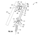
図6Aは、組み立てられたときに、(a)球ジョイント610、(b)少なくとも並進自由度を有するジョイント630、および(c)脊椎手術装置650の球ジョイント構成要素652と嵌合するように構成された球ジョイント構成要素622を形成する1つの例示的な単椎弓根標的化システム600を示す図である。脊椎手術装置650は、ジョイント構成要素152を球ジョイント構成要素として実装する脊椎手術装置150の実施形態である。単椎弓根標的化システム600は、1つのコネクタ431、ジョイント430、および1つのジョイント420を実装する単椎弓根標的化システム400の実施形態である。球ジョイント構成要素622はジョイント構成要素122の一実施形態であり、ジョイント610はジョイント430の実施形態であり、ジョイント630はジョイント420の実施形態である。単椎弓根標的化システム600は、方法500、501、502および503のいずれかを実施するために使用され得る。
6A is configured to mate with (a) a ball joint 610, (b) a joint 630 having at least translational freedom, and (c) a ball
単椎弓根標的化システム600は、ファスナ110と、球ジョイント610を介してファスナ110と接続するように構成された位置決めアーム620と、ジョイント630を介して位置決めアーム620と接続するように構成されたコネクタ640とを含む。コネクタ640は、さらに、球ジョイント構成要素622を実装する。ジョイント610は、直交回転方向612、614、および616によって示されるように、3回転自由度を有する。本明細書の範囲から逸脱することなく、ジョイント610は、図6に示されていない方向に回転することができる。ジョイント構成要素622は、ジョイント構成要素652と嵌合するように構成され、直交回転方向658、654、および656によって示されるような3回転自由度を有するジョイントを形成する。本発明の範囲から逸脱することなく、このジョイントは、図6に示されていない方向に回転することができる。
Single
ジョイント630は、方向632によって示されるように、位置決めアーム620に沿って並進自由度を有する。位置決めアーム620は、ジョイント610からジョイント630を通って延びる長手方向軸628を有する。図6に示す例示の実施形態において、位置決めアーム620は、ジョイント610のジョイント構成要素を実装する位置決めアーム620の部分を除く位置決めアームの全長に対して、長手方向軸628に直交する実質的に一定の断面を有する。コネクタ640は、この実質的に一定の断面の範囲に関連付けられた任意の位置で位置決めアームと接続することができる。したがって、球ジョイント610と、ジョイント構成要素622がジョイント構成要素652と嵌合するときに形成される球ジョイントと、の間の距離は、方向632にわたる寸法で調整され得る。
本明細書の範囲から逸脱することなく、長手方向軸628に沿った位置決めアーム620の部分のみが実質的に一定の横断面を有することができ、コネクタ640はこの部分内の位置決めアームと接続することができる。同様に、位置決めアーム620の少なくとも一部は、長手方向軸628が湾曲するように湾曲していてもよい。
Without departing from the scope herein, only the portion of the
一実施形態では、位置決めアーム620、または長手方向軸628と直交する実質的に一定の断面を有する位置決めアーム620の少なくとも一部分は円筒形である。この実施形態では、ジョイント630は、コネクタ640が長手方向軸628の周りで回転することをさらに可能にする円筒形ジョイントである。
In one embodiment, the
球ジョイント610およびジョイント630は協働して、図3Aにおいてジョイント構成要素122について図示されているように、ファスナ110に対するジョイント構成要素622の3並進自由度を提供する。ジョイント構成要素622をジョイント構成要素652と嵌合するときに形成される球形ジョイントは、図3Bに示すように、ファスナ110に対する脊椎手術装置150の3回転自由度を提供する。
一実施形態では、位置決めアーム620はカニューレ挿入され、球ジョイント610に関連する位置決めアーム620の端部から位置決めアーム620の反対側の端部まで位置決めアーム620の全長にわたって延在するカニューレ挿入部624を有する。カニューレ挿入部624は、位置決めアーム620を通ってファスナ110にアクセスすることを可能にするように機能し得る。任意選択で、ファスナ110は、カニューレ挿入部618を有する。カニューレ挿入部618は、ファスナ110がガイドワイヤに沿って椎弓根176に挿入され得るように、ガイドワイヤを適合させ得る。カニューレ挿入部624およびカニューレ挿入部618の両方を含む単椎弓根標的化システム600の実施形態では、ファスナ110をガイドワイヤに沿って椎弓根176に挿入する前に、位置決めアーム620をファスナ110に接続することができる。そのような実施形態では、単椎弓根標的化システム600は、ファスナ110をガイドワイヤに沿って椎弓根176に挿入する前に、完全に組み立てられ、任意選択で脊椎手術装置650と接続されてもよい。
In one embodiment, the
単椎弓根標的化システム600は、ジョイント610、ジョイント630、およびジョイント構成要素622および652を嵌合することによって形成されたジョイントのうちの1つまたは複数をそれぞれ所望の構成にロックするための1つまたは複数のロック装置692、694、および696を含むことができる。ロック装置692はロック装置434の実施形態であり、ロック装置694はロック装置424の実施形態であり、ロック装置696はロック装置414の実施形態である。本明細書の範囲から逸脱することなく、2つ以上のロック装置692、694、および696を単一のロック装置に実装することができる。ロック装置692、694、および696のそれぞれは、手で作動されてもよく、および/またはツールによって作動されてもよい。
The single
単椎弓根標的化システム600は、組み立てられた形態で、またはユーザによって実行される少なくともいくつかの組み立てを必要とする形態で、ユーザに提供されてもよい。例えば、単椎弓根標的化システム600は、ユーザによって組み立てられる別個のファスナ110、別個の位置決めアーム620、および別個のコネクタ640としてユーザに提供されてもよい。他の例では、単椎弓根標的化システム600は、位置決めアーム620およびファスナ110がジョイント610を介して互いに接続されているが、そこからコネクタ640が分離された状態でユーザに提供される。さらに、ファスナ110は、単椎弓根標的化システム100を参照して説明したように、ファスナ110を形成するためにユーザによって組み立てられる2つ以上の別個の部品としてユーザに提供されてもよい。
The single
図56〜図59を参照して以下にさらに詳細に説明するように、単椎弓根標的化システム600は、それぞれが単椎弓根標的化システム600と同じ機能性を有するが、脊椎172の異なる構造または患者170の骨盤に固定され得る、脊椎固定式標的化システムに容易に拡張される。このような脊椎固定式標的化システムは、患者170の頸椎、胸椎、および/または腰椎の後方脊椎手術において使用され得る。
As described in further detail below with reference to FIGS. 56-59, the single
図6Bは、経皮椎弓根ねじ670およびコネクタ660に基づく1つの例示的な単椎弓根標的化システム602を示す図である。コネクタ660は、椎弓根176に固定された経皮椎弓根ねじ670に脊椎手術装置650を接続するように構成される。単椎弓根標的化システム602は、単椎弓根標的化システム450および単椎弓根標的化システム600の実施形態である。コネクタ660は、コネクタ200の実施形態である。単椎弓根標的化システム600(図6Aに示す)と比較して、位置決めアーム620、ジョイント610、およびファスナ110は、経皮椎弓根ねじ670によって置き換えられる。
FIG. 6B illustrates one exemplary single
経皮椎弓根ねじ670は、経皮椎弓根ねじ212の実施形態であり、(a)頭部673を有する椎弓根ねじ672、(b)頭部673を有する球ジョイント680を形成するソケット674、および(c)取り外し可能なガイド延長部676を含む。椎弓根ねじ672、頭部673、ソケット674、球ジョイント680、および取り外し可能なガイド延長部676は、それぞれ、椎弓根ねじ220、頭部226、ソケット230、球ジョイント250、および取り外し可能なガイド延長部240の実施形態である。取り外し可能なガイド延長部676は、取り外し可能なガイド延長部676のソケット674から最も離れた端部から少なくとも頭部673まで延びるカニューレ挿入部624を含む。任意選択で、椎弓根ねじ672はカニューレ挿入部618を含む。球ジョイント680は、ジョイント610について説明したように3回転自由度を有する。
取り外し可能なガイド延長部676およびソケット674は、位置決めアーム620の実施形態を形成する。コネクタ660は、(a)コネクタ640、(b)ジョイント構成要素622、および(c)図6Aを参照してジョイント630および位置決めアーム620について説明したように、方向632に取り外し可能なガイド延長部676に沿ってスライドするように構成されたジョイント630のジョイント構成要素を含む。
一実施形態では、取り外し可能なガイド延長部676は、取り外し可能なガイド延長部676をソケット674に取り付けることができ、取り外し可能なガイド延長部674をソケット674から取り外すことができるように、ソケット674に結合される。一例では、取り外し可能なガイド延長部676はソケット674にねじ込まれ、ソケット674からねじを外すことによってソケット674から取り外すことができる。他の実施形態では、取り外し可能なガイド延長部676は、脆弱な接続部を介してソケット674に接続され、脆弱な接続を断つことによってソケット674から切り離され得る。一例では、取り外し可能なガイド延長部676は、ソケット674と一体的に形成される。取り外し可能なガイド部676は、実質的に円筒形であってもよい。あるいは、取り外し可能なガイド部676の少なくとも一部分は、円筒形状の一部のみを含む。このような1つの例では、取り外し可能なガイド部676は、軸628に沿って配向された1つまたは複数の(例えば2つの)ブレイクオフブレードであり、カニューレ挿入部624は、取り外し可能なガイド部676のソケット674から最も離れた端部から、および、2つのブレイクオフブレードの間の開口部を通してアクセスされ得る。
In one embodiment, the
単椎弓根標的化システム602は、カニューレ挿入部624内に適合し、ソケット674および/または取り外し可能なガイド部676と係合して頭部673に圧力を加えて球ジョイント680を所望の構成にロックするシャフトの形状のロックドライバ693として、ロック装置692を実装することができる。一実施形態では、ロックドライバ693は、取り外し可能なガイド延長部676のブレイクオフブレードを安定させるように構成され、ロック装置694を使用してコネクタ660を取り外し可能なガイド部676にロックするときに、これらのブレイクオフブレードの意図しない破損を防止する。例えば、ロックドライバ693の外径は、ロック装置694によって加えられる内向きの圧力に対抗するために、カニューレ挿入部624の内径に十分に近づけてもよい。ロックドライバ693は、手動で作動させることができ、および/またはツールによって作動させることができる。本明細書の範囲から逸脱することなく、ロックドライバ693は、ロック装置692の代替の実装形態に置き換えることができる。例えば、ロック装置692のこのような代替の実装形態は、第三者の経皮椎弓根ねじの特定の特徴に適合させることができる。
Single
本明細書の範囲から逸脱することなく、コネクタ660は、第三者の経皮椎弓根ねじ670および第三者の脊椎手術装置650と協働して手術部位270を標的に定めるように構成された独立型アイテムとして供給されてもよい。コネクタ660は、コネクタ200の実施形態である。
Without departing from the scope herein, the
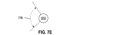
また、図7Aおよび図7Bは、単椎弓根標的化システム600および602の追加の回転自由度を示す図である。図7Aおよび図7Bは、一緒に見るのが最適である。
7A and 7B also illustrate additional rotational degrees of freedom for single
点710は、ジョイント610(またはジョイント680)の位置を示し、点722は、ジョイント構成要素622の位置を示す。固定点710および722が与えられると、ジョイント630は、ジョイント構成要素622が位置決めアーム620(または着脱可能なガイド延長部676)と反対側を向く方向が、点710および722によって規定される軸790の周りで回転することができるように、円形の軌道760に沿って動くことができる。図7Aは、ジョイント630が円形の軌道760に沿った位置730に配置されたときのジョイント構成要素622の1つの例示的な対面方向750を示す。図7Bは、ジョイント630が円形の軌道760に沿って異なる位置730’に配置されたときのジョイント構成要素622の異なる例示的な対面方向750’を示す。この追加の回転自由度は、ジョイント610(またはジョイント680)とジョイント630との間の距離715の範囲で達成され得る。
図7Aおよび図7Bに示すように、ジョイント構成要素622の対面方向を変える自由度は、脊椎手術装置650の所望の軌道を達成する能力を高める。
As shown in FIGS. 7A and 7B, the degree of freedom to change the facing direction of the
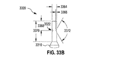
図7Cは、単椎弓根標的化システム600のジョイント610の1つの例示的な角度範囲を示す図であり、ファスナ110の長手方向軸629に直交する任意の軸の周りで回転するための同じ角度範囲を有する対称ジョイントとしてジョイント610が実装されている。図7Cは、長手方向軸629に対する位置決めアーム620の2つの異なる向きにおける、ファスナ110、ジョイント610、および位置決めアーム620の側面図である。位置決めアーム620の1つの極端な向きは、長手方向軸628(1)を有する位置決めアーム620(1)として示されている。位置決めアーム620の反対の極端な向きは、長手方向軸628(2)を有する位置決めアーム620(2)として示されている。ジョイント610は、角度範囲770を有する。一実施形態では、角度範囲770は、(ファスナ110の長手方向軸から離れる角度範囲が20度から30度の範囲にあるように)40度から60度の範囲内にある。他の実施形態では、角度範囲770は、少なくとも70度であり、椎弓根176に対する脊椎手術装置650の位置および向きについてより大きな柔軟性を提供する。そのような一例では、角度範囲770は、70度から75度の間である。
FIG. 7C is a diagram illustrating one exemplary angular range of the joint 610 of the single
図7Dおよび図7Eは、単椎弓根標的化システム600のジョイント610の1つの例示的な角度範囲を示す図であり、いくつかの方向に拡張された角度範囲を有する非対称ジョイントとしてジョイント610が実装されている。図7Dは、長手方向軸629に対する位置決めアーム620の2つの異なる向きにおける、ファスナ110、ジョイント610、および位置決めアーム620の側面図である。図7Eは、長手方向軸629に沿った観察方向におけるジョイント610の断面図である。図7Dおよび図7Eは、一緒に見るのが最適である。
7D and 7E are diagrams illustrating one exemplary angular range of the joint 610 of the single
ジョイント610は、角度部776として図7Eに示される方向範囲内の拡大された角度範囲を有する。1つの使用シナリオでは、単椎弓根標的化システム600は、手術部位270の対側を脊椎手術装置650に対する標的とするために使用され、ジョイント部610は、角度部776が脊椎172に対向するように有利に配向される。角度部776の外側では、ジョイント610は、図7Cに示す対称的な実施形態と同じ角度範囲を有する。長手方向軸628(2)を有する位置決めアーム620(2)として示される位置決めアーム620の極端な向きは、角度部774の外側にあり、長手方向軸629から離れる角度範囲774を有する。角度範囲774は角度範囲770の半分である。位置決めアーム620の他の極端な向きは、長手方向軸628(3)を有する位置決めアーム620(3)として示されている。この極端な向きは、角度部776内にある。角度部776内で、ジョイント610は、長手方向軸629から離れる角度範囲772を有する。角度範囲772は、角度範囲774より大きい。一実施形態では、角度範囲772は、角度範囲774を10度から35度の間だけ超える。一例では、角度部776は、図7Eの平面内で70度から150度の範囲の角度の広がりを有する。
本明細書では、「対側」とは脊椎172の反対側を指し、例えば、手術部位270は、脊椎172の左側の椎弓根176に固定された単椎弓根標的化システム100について脊椎172の右側から対側で標的にされる。対照的に、「同側」とは脊椎172の同じ側を指し、例えば、手術部位270は、脊椎172の左側の椎弓根176に固定された単椎弓根標的化システム100について脊椎172の左側から同側に標的にされる。
As used herein, “opposite” refers to the opposite side of the
本明細書の範囲から逸脱することなく、図7C〜7Eは、単椎弓根標的化システム602にも適用され、この場合、図7C〜7Eのファスナ110、ジョイント610、および位置決めアーム620はそれぞれ、椎弓根ねじ672、ジョイント680、および取り外し可能なガイド部676を示す。
Without departing from the scope herein, FIGS. 7C-7E also apply to the single
図8Aは、後方脊椎手術のための単椎弓根標的化システムを操作するための1つの例示的な方法800を示す図である。方法800は、方法500および501のそれぞれの一部の実施形態であり、方法500および501のいずれかまたは両方で実施することができる。方法800は、例えば、単椎弓根標的化システム600または602によって実行される。
FIG. 8A shows one
ステップ830は、椎弓根176に固定された単椎弓根標的化システムを操作し、単椎弓根標的化システム600または602などの単椎弓根標的化システムを介して、椎弓根176に固定された脊椎手術装置650を操作する。ステップ830は、ステップ530および531のそれぞれの実施形態である。ステップ830は、ステップ832、834および836を含む。
Step 830 operates a single pedicle targeting system secured to the
ステップ832は、単椎弓根標的化システムの第1のジョイントを操作する。この第1のジョイントは、3回転自由度を有し、椎弓根176に対して固定された位置を有する。ステップ832の一例では、外科医180は、単椎弓根標的化システム600の球ジョイント610を操作する。ステップ832の他の例では、外科医180は、単椎弓根標的化システム602の球ジョイント680を操作する。
Step 832 operates the first joint of the single pedicle targeting system. This first joint has three rotational degrees of freedom and has a fixed position relative to the
ステップ834は、3回転自由度を有する第2のジョイントを操作する。この第2のジョイントは、脊椎手術装置650を単椎弓根標的化システムに接続する。ステップ834の一例では、外科医180は、単椎弓根標的化システム600または602のジョイント構成要素622および652によって形成された球ジョイントを操作する。
Step 834 operates a second joint having three rotational degrees of freedom. This second joint connects the
ステップ836は、単椎弓根標的化システムの第3のジョイントの並進自由度を操作する。この第3のジョイントは、第1のジョイントと第2のジョイントとの間に結合される。ステップ836の一例では、外科医180は、単椎弓根標的化システム600または602のジョイント630を操作する。
Step 836 manipulates the translational freedom of the third joint of the single pedicle targeting system. The third joint is coupled between the first joint and the second joint. In one example of
一実施形態では、方法800は、第1のジョイントと、任意選択で第2および第3のジョイントの一方または両方をロックして、椎弓根176に対する脊椎手術装置650の動きを少なくとも制限するステップ840をさらに含む。ステップ840は、ステップ540の実施形態である。ステップ840の一例では、外科医180は、ロック装置692を係合して、球ジョイント610をロックする、またはロックドライバ693を係合して球ジョイント680をロックする。外科医180は、ロック装置694および696のうちの一方または両方を係合して、ジョイント630とジョイント構成要素622および652を嵌合することによって形成されるジョイントとをそれぞれロックする。
In one embodiment, the
図8Bは、椎弓根176に対する脊椎手術装置150の位置および向きを維持しながら、脊椎手術装置150を椎弓根176に結合するための例示的な方法850を示す図である。方法850は、方法503のステップ523または方法502のステップ533として実施することができる。
FIG. 8B illustrates an
ステップ860において、方法850は、椎弓根176に対する脊椎手術装置150の位置および向きに従ってマニピュレータを組み立てて調整する。ステップ860は、ステップ862および864を含む。ステップ862は、図8Aを参照して上述した第3のジョイントを組み立てる。ステップ862の一例では、外科医180は、単椎弓根標的化システム600または602のジョイント630を組み立てる。ステップ864は、第1のジョイント(図8Aを参照して上述した)および第3のジョイントを操作して、椎弓根176に対する脊椎手術装置150の位置および向きを維持しながら脊椎手術装置150を椎弓根176に固定するために、第2のジョイント(図8Aを参照して上述した)を組み立てる。ステップ864の一例では、外科医180は、単椎弓根標的化システム600のジョイント610と、単椎弓根標的化システム600のジョイント630とを操作して、ジョイント構成要素622および652によって形成される球ジョイントを組み立てる。ステップ864の他の例では、外科医180は、単椎弓根標的化システム602のジョイント680および単椎弓根標的化システム602のジョイント630を操作して、ジョイント構成要素622および652によって形成される球ジョイントを組み立てる。
In
任意選択で、方法850はさらにステップ840を含む。
Optionally,
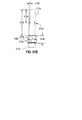
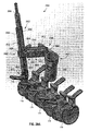
図9および図10は、単椎弓根標的化システム600の実施形態である後方脊椎手術用の1つの例示的な単椎弓根標的化システム900を示す図である。単椎弓根標的化システム900を使用して、方法500、501、および502のいずれかを実行することができる。図9は、椎弓根176に固定されたときの単椎弓根標的化システム900を斜視図で示す図である。図10は、単椎弓根標的化システム900のファスナを椎弓根176にねじ込むために使用されるドライバとともに単椎弓根標的化システム900を分解図で示す図である。図9および図10は、一緒に見るのが最適である。
9 and 10 illustrate one exemplary single
単椎弓根標的化システム900は、ファスナ1010(図9では見えない)、位置決めアーム920、およびクランプ940を含む。ファスナ1010、位置決めアーム920、およびファスナ940はそれぞれ、ファスナ110、位置決めアーム620、およびコネクタ640の実施形態である。クランプ940は、コネクタ200の一実施形態でもある。
Single
位置決めアーム920は、(a)カニューレ挿入部1022を有するシリンダ1020と、(b)ソケット1023とを含む。ソケット1023は、シリンダ1020を受け入れるように構成された開口部1018を有する。一実施形態では、シリンダ1020は、ソケット1023に恒久的に固定され、位置決めアーム920を形成する。例えば、シリンダ1020は、ソケット1023の所定位置に溶接されてもよい。他の実施形態では、シリンダ1020およびソケット1023は、シリンダ1020がソケット1023に取り外し可能に配置され得るように構成される。例えば、シリンダ1020がソケット1023にねじ込まれ得るように、シリンダ1020は雄ねじ(図示せず)を有してもよく、ソケット1023は雌ねじ(図示せず)を有してもよい。
The
ファスナ1010は、ボールの一部を含む頭部1013を有する。頭部1013は、ジョイント構成要素224の実施形態を形成し、ソケット1023は、ジョイント構成要素432の実施形態を形成する。頭部1013およびソケット1023は、嵌合してボールソケットジョイント910を形成するように構成される。ジョイント910は、ジョイント610の実施形態である。ジョイント910は、ジョイント610について図7C〜図7Eを参照して説明した角度範囲を有することができる。
The
クランプ940は、2つのクランプ部品1042および1044を含む。クランプ部品1042は溝1043を有し、クランプ部品1044は溝1045を有する。クランプ部品1042および1044は、シリンダ1020の周りで溝1043および1045を用いて一緒にされ、円筒形ジョイント930を形成するように構成される。溝1043および1045は協働してジョイント構成要素622の実施形態を形成する。円筒形ジョイント930はジョイント630の実施形態である。クランプ940は、ソケット1023内に配置されたものを除いて、シリンダ1020の長さに沿った任意の位置でシリンダ1020に取り付けられてもよい。溝1043および1045から離れたクランプ940の部分は、脊椎手術装置960の突起962と嵌合して、球ジョイント950を形成するように構成される。球ジョイント950は、ジョイント構成要素622および652によって形成される球ジョイントの実施形態である。一実装形態では、クランプ940は、シリンダ1020の長手方向軸に直交する方向に、25ミリメートル以下、例えば約18ミリメートルの全長を有する。この長さは、同側の脊椎手術処置を実施するために実用的である。
脊椎手術装置960は、脊椎手術装置650の実施形態であり、突起部962は、ジョイント構成要素652の実施形態である。図9においてボール形状の突起部962を有する管状の開創器として示されているが、脊椎手術装置960は、他のタイプの脊椎手術装置であってもよく、突起部962は、本明細書の範囲から逸脱することなく、異なる形状を有してもよい。また、本明細書の範囲から逸脱することなく、クランプ940は、溝1043および1045の代わりに突起部を有してもよく、突起部は、突起部962の代わりに脊椎手術装置960のレセプタクルと嵌合して球ジョイント950を形成する。
単椎弓根標的化システム900は、カニューレ挿入部1022を介してシリンダ1020に挿入され、ソケット1023を介して頭部1013を押すことができるシャフトの形状のロックドライバ915をさらに含む。ロックドライバ915がシリンダ1020にねじ込まれ得るように、シリンダ1020は雌ねじ1025を有し、ロックドライバ915は雄ねじ1015を有する。雌ねじ1025と雄ねじ1015との間の接触は、頭部1013とロックドライバ915との間の圧力と協働して、ジョイント910をロックする。ロックドライバ915は、ロック装置692の実施形態である。
The single
単椎弓根標的化システム900はまた、クランプ部品1042および1044のうちの1つを通して挿入され、クランプ部品1042および1044のうちの他の1つにねじ込まれ、ジョイント930および950の両方をロックするように、クランプ部品1042および1044をシリンダ1020および突起部962上でともに締め付けることができるロックファスナ945も含む。ロックファスナ945は、ロック装置694および696の両方を実装する。
Single
単椎弓根標的化システム900または脊椎手術装置960の1つまたは複数の部分は、アンチグレア表面またはグレア低減表面を有することができる。脊椎手術装置960が管状の開創器として実装される一実施形態では、管状の開創器の内側表面は、アンチグレア特性またはグレア低減特性を有し得る。例えば、管状の開創器は、陽極酸化金属であってもよい。さらに、単椎弓根標的化システム900または脊椎手術装置960の1つまたは複数の部分は、これらの部分が手術部位270の画像化に基づく視覚化を妨げないように、手術部位270の画像化に使用される放射線に対して半透明である。
One or more portions of the single
任意選択で、単椎弓根標的化システム900は、ねじ回し1080を含む。ロックドライバ915がカニューレ挿入部1022に配置されていないときに、ねじ回し1080はカニューレ挿入部1022に適合する。ねじ回し1080を用いて、位置決めアーム920を介してファスナ1010を椎弓根176にねじ込むことができる。ファスナ1010を椎弓根176にねじ込んだ後、ジョイント910が自由に回転し、ロックドライバ915がシリンダ1020に挿入されるように、ねじ回し1080をシリンダ1020から取り外すことができる。ねじ回し1080は、カニューレ挿入部1022を介して頭部1013に到達するのに十分な長さ1082を有する。一例では、長さ1082は3〜6インチの範囲である。図10には示されていないが、単椎弓根標的化システム900は、ロックドライバ915を作動させるのに適した、より短いバージョンのねじ回し1080をさらに含むことができる。
Optionally, the single
特定の実施形態において、単椎弓根標的化システム900は、脊椎手術装置960を含む。
In certain embodiments, the single
単椎弓根標的化システム900は、組み立てられた形態で、またはユーザによって実行される少なくともいくつかの組み立てを必要とする形態で、ユーザに提供されてもよい。例えば、単椎弓根標的化システム900は、図10に示されるようにユーザに提供されてもよく、任意選択で、ソケット1023に恒久的に固定されたシリンダ1020と、ソケット1023に接続されたファスナ1010とを有する。
The single
図56〜図59を参照して以下にさらに詳細に説明するように、単椎弓根標的化システム900は、それぞれが単椎弓根標的化システム900と同じ機能性を有するが、脊椎172の異なる構造または患者170の骨盤に固定され得る、脊椎固定式標的化システムに容易に拡張される。このような脊椎固定式標的化システムは、患者170の頸椎、胸椎、および/または腰椎の後方脊椎手術において使用され得る。
As described in more detail below with reference to FIGS. 56-59, the single
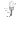
図11Aおよび11Bは、位置決めアーム920がジョイント910を介してファスナ1010に結合されたときの、位置決めアーム920およびファスナ1010の例示的な実施形態をより詳細に示す断面図である。図11Aは、位置決めアーム920およびファスナ1010のすべてを示している。図11Bは、部分1130の拡大図である。図11Aおよび図11Bは、一緒に見るのが最適である。
FIGS. 11A and 11B are cross-sectional views illustrating in more detail exemplary embodiments of
ファスナ1010は、頭部1013から最も遠い非ねじ部分1111と、非ねじ部分1111と頭部1013との間のねじ部分1112とを含む。したがって、ファスナ1010は、組み合わされた錐/タップである。非ねじ部分1111は長さ1194を有し、ねじ部分1112は長さ1192を有する。一例では、長さ1192および1194のそれぞれは、0.5インチ(12.7mm)〜1.5インチ(38.1mm)の間の範囲である。頭部1013は、ドライバ1080と一致するレセプタクル1114を含む。他の実施形態では、ファスナ1010は椎弓根ねじであり、単椎弓根標的化システム900の他のすべての部分を取り除いた後に脊椎172に残すことができる。
The
シリンダ1020は、長さ1190を有する。長さ1190は、脊椎手術装置960を有する単椎弓根標的化システム900が、椎弓根176から手術部位270に達するのに十分な距離を有するような長さである。一例では、長さ1190は3〜5インチ(76.2〜127mm)の範囲であり、これは、椎骨178に関連するまたは椎骨178に隣接する脊椎部分に到達するために実用的な長さである。他の例では、長さ1190は5インチ〜10インチ(127〜254mm)の範囲であり、これは、椎骨178に近接するが隣接しない脊椎部分に到達するために実用的な長さである。
The
シリンダ1020は、0.3〜0.7インチ(7.62〜17.78mm)の範囲の直径1182を有してもよく、ソケット1023は、0.35〜1.0インチ(8.89〜25.4mm)の範囲の直径1180を有してもよい。
The
図12Aおよび図12Bは、クランプ940の1つの例示的な実施形態を直交図でさらに詳細に示す図である。図12Aおよび図12Bは、一緒に見るのが最適である。クランプ部品1042および1044がほぼ接触しているときには、図12Bに示すように、溝1043および1045によって形成される開口部の直径1240は、クランプ940がシリンダ1020をしっかりと締め付けるように、シリンダ1020の直径1182と同様である。また、クランプ部品1042および1044がほぼ接触しているときには、図12Bに示すように、クランプ部品1042および1044は、脊椎手術装置960の突起部962と嵌合するためのレセプタクル1220を形成する。
12A and 12B are diagrams illustrating one exemplary embodiment of the
例示的な実装形態では、クランプ部品1042および1044のそれぞれは、位置決めアーム920に関連する端部から脊椎手術装置960に関連する端部までの長さ1212を、20〜50ミリメートルの範囲で有する。長さ1212のこの範囲は、溝1043および1045、レセプタクル1220およびロックファスナ945を収容するのに実用的であり、最も近い椎間板の同側のような椎弓根176の近くの手術部位270を標的にするのに適している。最も近い椎間板の対側のような、椎弓根176からさらに離れた手術部位270を標的とすることが意図される実施形態では、長さ1212は、50〜100ミリメートルの範囲であり得る。
In the exemplary implementation, each of the
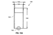
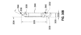
図13Aおよび図13Bは、脊椎手術装置960の実施形態である1つの例示的な管状の開創器1360を直交断面図で示す図である。管状の開創器1360は、患者170の組織を後退させて手術部位270へのアクセスを提供する。管状の開創器1360は、シリンダ1350およびボール1352を含む。ボール1352は、突起部962の実施形態である。
FIGS. 13A and 13B show one
シリンダ1350は、外径1380、内径1382、および長さ1384を有する。一例では、外径1380は15〜40ミリメートルの範囲、例えば20〜30ミリメートルまたは16〜26ミリメートルであり、内径1382は外径1380より約1〜3ミリメートル小さい。これらの直径1380および1380の値は、手術部位270にアクセスするのに十分な空間を提供しながら、典型的な手術部位270を露出させるのに適している。長さ1384は、30〜90ミリメートルの範囲、例えば50〜60ミリメートルの範囲であってもよい。この長さ1384の値は、手術部位270で作動するためにシリンダ1350を通して挿入された手術ツールの不必要な運動の制限をシリンダ1350が課すほど患者170の皮膚表面の上まで延ばすことなく、患者170の脊椎172と皮膚表面との間の組織を後退させるのに適している。
任意選択で、管状の開創器1360の外径は、ボール1352から最も離れた管状の開創器1360の端部で、患者170の組織への管状の開創器1360の挿入を容易にするためにテーパになっている。
Optionally, the outer diameter of
ボール1352は直径1386を有する。一例では、直径1386はシリンダ1020の直径と同様であり、例えば0.3〜0.7インチ(7.62〜17.78mm)の範囲である。
本明細書の範囲から逸脱することなく、シリンダ1350は、非円形の断面を有することができる。例えば、シリンダ1350の断面は、楕円形または卵形であってもよいし、または三角形、矩形、正方形、五角形、六角形、または八角形などの多角形の形状を有してもよい。さらに、シリンダ1350は、複数の分離可能な部品から構成されてもよい。このような実装形態の1つでは、複数の分離可能な部品のうちの1つは、例えば、管状の開創器1360の形状および/またはサイズを変更するために、または管状の開創器1360に窓を形成するために取り外し可能であり得る。
Without departing from the scope herein, the
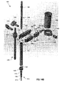
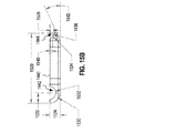
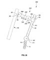
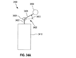
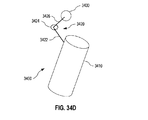
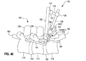
また、図14A〜図14Cは、単椎弓根標的化システム600および単椎弓根標的化システム400の実施形態である、後方脊椎手術のための他の例示的な単椎弓根標的化システム1400を示す図である。単椎弓根標的化システム1400を使用して、方法500、501、および502のいずれかを実行することができる。図14Aは、椎弓根176に固定され、対側の作業方向から手術部位270を標的とするために脊椎手術装置1493と結合された、組み立てられた形態の単椎弓根標的化システム1400を示している。図14Bは、単椎弓根標的化システム1400を分解図で示している。図14Cは、ねじ回しを分解図で示している。図14A〜図14Cは、一緒に見るのが最適である。
14A-14C also illustrate other exemplary single pedicle targeting systems for posterior spine surgery that are embodiments of the single
単椎弓根標的化システム1400は、ファスナ1410、位置決めアーム1402、およびコネクタ1404を含む。ファスナ1410、位置決めアーム1402、およびコネクタ1404は、それぞれ、ファスナ110、位置決めアーム620、およびコネクタ640の実施形態である。コネクタ1404は、コネクタ200の実施形態でもある。
Single
位置決めアーム1402は、カニューレ挿入部1432およびソケット1420を備えたシリンダ1430を含む。ソケット1420は、シリンダ1430を受け入れるように構成された開口部1421を有する。一実施形態では、シリンダ1430は、ソケット1420に恒久的に固定され、位置決めアーム1402を形成する。例えば、シリンダ1430は、ソケット1420の所定の場所に溶接されてもよい。他の実施形態では、シリンダ1430およびソケット1420は、シリンダ1430がソケット1420に取り外し可能に配置されるように構成される。例えば、シリンダ1430がソケット1420にねじ込まれ得るように、シリンダ1430は雄ねじ(図示せず)を有してもよく、ソケット1420は雌ねじ(図示せず)を有してもよい。
The
ファスナ1410は、ボールの一部を含む頭部1412を有する。頭部1412は、ジョイント構成要素224の実施形態を形成し、ソケット1420は、ジョイント構成要素432の実施形態を形成する。頭部1412およびソケット1420は、嵌合してボールソケットジョイント1406を形成するように構成される。ジョイント1406は、ジョイント610の実施形態である。ジョイント1406は、ジョイント610について図7C〜図7Eを参照して説明したような角度範囲を有することができる。ファスナ1410は、頭部1412から最も遠い非ねじ部分1414および非ねじ部分1414に隣接するねじ部分1416を有するタップ錐として図14A〜14Cに示されている。本発明の範囲から逸脱することなく、ファスナ1410は異なるタイプのファスナであってもよい。
The
コネクタ1404は、2つのクランプ部品1440および1449を含む。クランプ部品1449は、クランプサブ部品1450および1460として実装される。クランプ部品1440は溝1442を有し、クランプ部品1449は溝1462を有する。クランプ部品1440および1449は、シリンダ1430の周りで溝1442および1462を用いて一緒にされ、円筒形ジョイント1408を形成するように構成される。円筒形ジョイント1408は、ジョイント630の実施形態である。コネクタ1404は、ソケット1420内に配置されたものを除いて、シリンダ1430の長さに沿った任意の位置でシリンダ1430に取り付けられてもよい。クランプ部品1440および1449のそれぞれの(図14Aおよび図14Bでは直接見えない)レセプタクル1444および1452は、カプラ1490の突起部1496と嵌合して球ジョイント1409を形成するように構成される。カプラ1490は、脊椎手術装置1493と取り外し可能に結合するように構成される。球ジョイント1409は、ジョイント構成要素622および652によって形成される球ジョイントの実施形態である。
図14Aおよび図14Bに示されているように、コネクタ1404は、手術部位270を標的とする対側に適合する長さを有する。しかしながら、コネクタ1404は、本明細書の範囲から逸脱することなく、椎弓根176に隣接する脊椎部分で手術部位270を同側に標的するために、図14に示されるよりも短くてもよい。同様に、コネクタ1404は、より遠くの手術部位270を標的とするために、図14Aおよび図14Bに示すよりも長くてもよい。
As shown in FIGS. 14A and 14B, the
脊椎手術装置1493は脊椎手術装置650の実施形態であり、突起部1496はジョイント構成要素652の実施形態である。また、図14Aおよび図14Bは、脊椎手術装置1493を管状の開創器であるように、および突起部1496がボール形状の突起部であるように示しているが、本明細書の範囲から逸脱することなく、脊椎手術装置1493は他のタイプの脊椎手術装置であってもよく、突起部1496は異なる形状であってもよい。また、本明細書の範囲から逸脱することなく、コネクタ1404は、溝1442および1462の代わりに突起部を有し、突起部は、突起部1496の代わりにカプラ1490のレセプタクルと嵌合して球ジョイント1409を形成してもよい。
本明細書の範囲から逸脱することなく、脊椎手術装置1493は、非円形断面の管状の開創器であってもよい。例えば、断面は、楕円形または卵形であってもよいし、または三角形、矩形、正方形、五角形、六角形、または八角形などの多角形の形状を有してもよい。さらに、この管状の開創器は、複数の分離可能な部品から構成されてもよい。このような実装形態の1つでは、複数の分離可能な部品のうちの1つは、例えば、管状の開創器の形状および/またはサイズを変更するために、または管状の開創器に窓を形成するために取り外し可能であり得る。
Without departing from the scope herein,
単椎弓根標的化システム1400は、カニューレ挿入部1432を介してシリンダ1430に挿入されてソケット1420を介して頭部1412を押すロックドライバ1480をさらに含む。ロックドライバ1480がシリンダ1430にねじ込まれ得るように、シリンダ1430は雌ねじ1434を有し、ロックドライバ1480は雄ねじ1482を有する。雌ねじ1434と雄ねじ1482との間の接触は、頭部1412とロックドライバ1480との間の圧力と協働して、ジョイント1406を所望の構成にロックする。ロックドライバ1480は、ロック装置692の実施形態である。図14A〜図14Cには示していないが、単椎弓根標的化システム1400は、ロックドライバ1480を作動させるためのツールを含むことができる。
Single
単椎弓根標的化システム1400は、また、クランプ部品1440および1449のうちの1つを通して挿入され、クランプ部品1440および1449のうちの他の1つにねじ込まれ、ジョイント1408および1409の両方を所望の構成にロックするように、クランプ部品1440および1449をシリンダ1430および突起部1496上でともに締め付けることができる2つのロックファスナ1405も含む。ロックファスナ1405は、ロック装置694および696を実装する。クランプ部品1449は、2つのクランプサブ部品1450および1460を含み、その間にヒンジ1455を有する。クランプサブ部品1450は、レセプタクル1452を含む。クランプサブ部品1460は、溝1462を含む。ヒンジ1455は、ジョイント1408および1409の互いに独立したロックを容易にする。
The single
カプラ1490は、突起部1496、リング1492、突起部1496をリング1492に接続する接続アーム1494、およびリング1492を脊椎手術装置1493に固定するように構成されたロックファスナ1497を含む。接続アーム1494は、単椎弓根標的化システム1400が、外科手術部位270への前後画像化経路を遮断することなく、手術部位270を対側で標的とすることを可能にする曲げ部分1495を有する。さらに、接続アーム1494は、脊椎手術装置1493の位置決めのための追加の柔軟性を提供する。図14Aおよび図14Bに示す実施形態では、曲げ部分1495は90度の角度を有する。しかしながら、曲げ部分1495の角度は、本明細書の範囲から逸脱することなく、60度〜120度の範囲内、または45度〜135度の範囲内にあってもよい。また、本明細書の範囲から逸脱することなく、リング1492は、図14Aおよび図14Bに示す脊椎手術装置1493とは異なる脊椎手術装置と結合するように構成された異なる形状の構成要素と置き換えることができる。さらに、リング1492は、脊椎手術装置1493を包むように構成される必要はないが、他の手段を介して脊椎手術装置1493に取り付けることができる他の構成要素と置き換えることができる。例えば、リング1492は、脊椎手術装置1493にねじ込まれるか、または脊椎手術装置1493の適切なレセプタクルに圧入される構成要素と置き換えることができる。
突起部1496は、ジョイント1409における摩擦を高めるためにエッチングを有してもよい。
The
図14Aおよび図14Bでは2つの直線部分を含むように示されるが、接続アーム1494は、代替の実施形態では、直線部分を含まないか、またはただ1つの直線部分のみを含み得る。例えば、接続アーム1494は、曲げ部分1495のみで構成することができ、曲げ部分1495は、リング1492および突起部1496に直接結合される。
Although shown in FIGS. 14A and 14B as including two straight portions, the connecting
図14Aおよび図14Bでは指掛け部を有するねじとして示されているが、ロックファスナ1405および1497は、本発明の範囲から逸脱することなく、ツールによって作動するように構成することができる。例えば、ロックファスナ1405および1497のうちの1つまたは複数は、止めねじであってもよい。各固定ファスナ1405を止めねじ(またはクランプ部品1440または1449にはめ込まれた他の形態のねじ)として実装する場合には、コネクタ1404から伸びるロックファスナ1405のバルクは除去されるか、または少なくとも低減され、患者170に対するクランプ1404の配置のさらなる自由度を提供することができる。また、本明細書の範囲から逸脱することなく、ロックファスナ1405は、(a)ロックファスナ1405の指掛け部が患者170から離れる角度を付けられ、ロックファスナ1405と患者170との間の干渉のリスクを低減する、または(b)ロックファスナ1405が止めねじまたは他のはめ込みねじとして実装される場合に、ロックファスナ1405を作動させるために使用されるツールが、患者170から離れる角度を付けられ、ツールと患者170との間の干渉のリスクを低減するように、斜めの角度でコネクタ1404を介して配向される。
Although shown as screws having finger hooks in FIGS. 14A and 14B,
他の実施形態では、ロックファスナ1405は、クランプ部品1440の表面1448から、またはクランプサブ部品1450の表面1458およびクランプサブ部品1460の表面1468のそれぞれからコネクタ1404にアクセスする。表面1448、1458および1468は、一般的に患者170と反対側に向いているので、この代替の実施形態は、ロックファスナ1405へのアクセスを容易にし、ロックファスナ1405と患者170との間の干渉のリスクを低減する。この代替の実施形態では、各ロックファスナ1405は、直角ギアまたはウォームギア(または当技術分野で知られている他の同様のギア)を含み、ロックファスナ1405の作動を、クランプ部品1449を用いたクランプ部品1440の締め付けに変換することができる。
In other embodiments, the
脊椎手術装置1493の長手方向軸に対するカプラ1490の向きは、実施される外科的処置および/または外科医180の好みに従って反転されてもよい。1つの例示的な使用シナリオでは、外科医180は、手術部位270を対側で標的とするための向きを有する単椎弓根標的化システム1400を使用し、脊椎手術装置1493の長手方向軸に対するカプラ1490の向きが図14Aに示されている。この向きは、手術部位270への前後画像化経路の外側にコネクタ1404を位置決めしながら、手術部位270を標的とすることを有利に可能にする。他の例示的な使用シナリオでは、脊椎手術装置1493の長手方向軸に対するカプラ1490の向きは、図14Aに示されるものと比較して反転され、手術部位270への前後画像化経路の外側にコネクタ1404を位置決めしながら、手術部位270を同側で標的にする。さらなる使用シナリオでは、外科医180は、単椎弓根標的化システム1400が同じ椎弓根176に取り付けられ、単椎弓根標的化システム1400が関連する手術部位270への前後画像化経路を妨害することなく対側および同側の2つの処置のそれぞれを実行することができるように、脊椎手術装置1493からカプラ1490を外し、カプラ1490の向きを反転させることによって、対側および同側の処置を切り替えることができる。
The orientation of
代替の実施形態では、突起部1496は、接続アーム1494を介して脊椎手術装置1493に恒久的にかつ強固に結合され、一体化されたカプラ脊椎手術装置を形成する。1つの例示的なシナリオでは、この一体化されたカプラ脊椎手術装置の2つの異なる実施形態が外科医180に供給され、同側および対側の処置の両方が可能となる。これらの2つの異なる実施形態は、上述したカプラ1490の2つの可能な向きと同様である。
In an alternative embodiment, the
単椎弓根標的化システム1400および/または脊椎手術装置1493の1つまたは複数の部分は、単椎弓根標的化システム900および脊椎手術装置960について上述したように、アンチグレアまたはグレア低減表面を有してもよい。さらに、単椎弓根標的化システム1400または脊椎手術装置1493の1つまたは複数の部分は、これらの部分が手術部位270の画像化ベースの視覚化を妨げないように、手術部位270の画像化に使用される放射線に対して半透明であってもよい。
One or more portions of the single
任意選択で、単椎弓根標的化システム1400は、ねじ回し1470を含む。ロックドライバ1480がカニューレ挿入部1432内に配置されていない場合には、ねじ回し1470は、カニューレ挿入部1432に嵌合する。ねじ回し1470は、位置決めアーム1402を介してファスナ1410に強固に接続してファスナ1410を椎弓根176にねじ込むために使用されてもよい。ねじ回し1470は、カニューレ挿入部1432を通って頭部1412に到達するのに十分な長さ1476の部分1474を有する。一例では、長さ1476は、3〜6インチ(76.2〜152.4mm)の範囲内にある。ねじ回し1470は、ねじ回し1470をファスナ1410に強固に結合するようにフランジ1473(部分1474の上部)に圧力を加えるために、雌ねじ1434に係合するように構成された雄ねじを備えたロックボルト1472を含む。図14A〜図14Cには示されていないが、単椎弓根標的化システム1400は、ファスナ1410を椎弓根176内にねじ込むためにねじ回し1470を作動させるためのツールを含み得る。ロックボルト1472は、ファスナ1410を後退させることなくロックボルト1472を緩めてファスナ1410からドライバ1470を取り外すことができるように、部分1474とは独立に自由に回転することができる。ファスナ1410からねじ回し1470を取り外した後、ジョイント1406が自由に回転し、ロックドライバ1480がシリンダ1430に挿入され得るように、ねじ回し1470は、シリンダ1430から取り除かれ得る。
Optionally, the single
特定の実施形態において、単椎弓根標的化システム1400は、脊椎手術装置1493を含む。単椎弓根標的化システム1400は、組み立てられた形態で、またはユーザによって実行される少なくともいくつかの組み立てを必要とする形態で、ユーザに提供されてもよい。
In certain embodiments, the single
本明細書の範囲から逸脱することなく、コネクタ1404は、第三者の経皮椎弓根ねじ212および第三者の脊椎手術装置150と協働して手術部位270を標的に定めるように構成された独立型アイテムとして供給されてもよい。コネクタ1404は、コネクタ200の実施形態である。同様の方法で、脊椎手術装置1493およびカプラ1490は、第三者の脊椎手術システムと協働するように構成された独立型アイテムとして供給されてもよい。
Without departing from the scope herein, the
また、本明細書の範囲から逸脱することなく、単椎弓根標的化システム1400のコネクタ1404をクランプ940に置き換えてもよく、単椎弓根標的化システム900のクランプ940をコネクタ1404に置き換えてもよい。同様に、単椎弓根標的化システム1400は、脊椎手術装置1493およびカプラ1490の代わりに脊椎手術装置960を利用してもよく、単椎弓根脊椎標的化システム900は、脊椎手術装置960の代わりに脊椎手術装置1493およびカプラ1490を利用してもよい。
Also, the
図56〜図59を参照して以下にさらに詳細に説明するように、単椎弓根標的化システム1400は、それぞれが単椎弓根標的化システム1400と同じ機能性を有するが、脊椎172の異なる構造または患者170の骨盤に固定され得る、脊椎固定式標的化システムに容易に拡張される。このような脊椎固定式標的化システムは、患者170の頸椎、胸椎、および/または腰椎の後方脊椎手術において使用され得る。
As described in more detail below with reference to FIGS. 56-59, the single
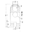
また、図15A〜図15Dは、クランプ部品1440の例示的な一実施形態をさらに詳細に示す図である。図15A〜図15Cは、クランプ部品1440の直交する側面図を示し、図15Dは、クランプ部品1440を斜視図で示している。図15A〜図15Dは、一緒に見るのが最適である。
15A-15D are diagrams illustrating an exemplary embodiment of the
クランプ部品1440は、長さ1510および断面寸法1516および1518を有する。クランプ部品1440は、ロックファスナ1405に係合するように構成されたねじ穴1562を含む。溝1442は、シリンダ軸がクランプ部品1440の断面範囲1516のわずかに外側に配置された円筒形である。これは、クランプ部品1440がシリンダ1430の周りでクランプサブ部品1460と一緒にされたときに、単にクランプ部品1440とクランプサブ部品1460との間に圧力を加えることとは対照的に、コネクタ1404がシリンダ1430に圧力を確実に加えるのを助ける。レセプタクル1444は球形である。球の中心は、クランプ部品1440が突起部1496の周りでクランプサブ部品1450と一緒にされたときに、単にクランプ部品1440とクランプサブ部品1450との間に圧力を加えることとは対照的に、コネクタ1404が突起部1496に圧力を確実に加えるのを助けるために、範囲1516のわずかに外側に配置される。
一実施形態では、ねじ穴1562は、1/4−20NCタイプであり、各ロックファスナ1405は、対応する1/4−20NC雄ねじを有する。一実施形態では、寸法1510、1512、1514、1516、1518、1520、1522、1524、および1526は、それぞれ、2.4850インチ(63.119mm)、1.9806インチ、0.7309インチ、0.3365インチ、0.5000インチ、2.3396インチ、0.3488インチ、0.3507インチ、および0.1120インチである(以下、インチの単位は、[]×2.4=[]mmの換算表に従ってミリメートルに換算することができます。)。溝1442の円筒中心からレセプタクル1444の球中心までのクランプ部品1440の長さ(図15Bにおいて寸法1520から寸法1522を差し引いた寸法として示されている)は、シリンダ1430の円筒中心と突起部1496の球中心との間の距離を定める。特定の実施形態では、この長さは、単椎弓根標的化システム1400が、椎弓根176に対して対側である方向から手術部位270を都合よく標的とすることができるように、50ミリメートル〜70ミリメートルの範囲、例えば60ミリメートルである。一実施形態では、曲率半径1530、1532、1534および1536は、それぞれ、0.3490インチ、0.2100インチ、0.1875インチおよび0.1467インチであり、角度1540および1542はそれぞれ、5度および25度である。角度1540は、レセプタクル1444内への傾斜した開口部を画定する。本明細書の範囲から逸脱することなく、クランプ部品1440の実際の寸法は、ここに列挙された寸法と異なってもよい。
In one embodiment, the threaded
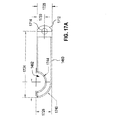
図16A〜図16Cは、クランプサブ部品1450の1つの例示的な実施形態をさらに詳細に示す図である。図16Aおよび図16Bは、クランプサブ部品1450の直交する側面図を示し、図16Cは、クランプサブ部品1450を斜視図で示している。図16A〜図16Cは、一緒に見るのが最適である。
FIGS. 16A-16C illustrate one exemplary embodiment of the
クランプサブ部品1450は、クランプサブ部品1460の整合特徴と協働してヒンジ1455を形成するスロット1610および貫通穴1614を含む。クランプサブ部品1450はさらに、ロックファスナ1405のうちの1つを受け入れるように構成された貫通孔1612を含む。レセプタクル1452は球形である。球の中心は、クランプ部品1440が突起部1496の周りでクランプサブ部品1450と一緒にされたときに、単にクランプ部品1440とクランプサブ部品1450との間に圧力を加えることとは対照的に、コネクタ1404が突起部1496に圧力を確実に加えるのを助けるために、範囲1636のわずかに外側(範囲1634によって示されている)に配置される。クランプサブ部品1450は、レセプタクル1452内への傾斜した開口部1616を有する。
一実施形態では、寸法1620、1622、1624、1626、1628、1630、1632、1634、1634、1636、および1638は、それぞれ、1.1531インチ、0.6250インチ、0.1250インチ、0.2500インチ、0.2500インチ、0.9840インチ、0.1250インチ、0.3507インチインチ、0.3382インチ、および0.1120インチである(インチの単位は、[]×2.4=[]mmの換算表に従ってミリメートルに換算することができます。)。一実施形態では、直径1640は0.1220インチである。一実施形態では、角度1642および1644はそれぞれ24.85度および5度である。レセプタクル1452は、レセプタクル1444と同様の曲率半径を有することができる。本明細書の範囲から逸脱することなく、クランプサブ部品1450の実際の寸法は、ここに列挙された寸法と異なってもよい。
In one embodiment,
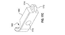
また、図17A〜図17Cは、クランプサブ部品1460の1つの例示的な実施形態をさらに詳細に示す図である。図17Aおよび17Bは、クランプサブ部品1460の直交する側面図を示し、図17Cはクランプサブ部品1460を斜視図で示している。図17A〜図17Cは、一緒に見るのが最適である。
17A-17C also illustrate one exemplary embodiment of the
クランプサブ部品1460は、スロット1610と嵌合するように構成された貫通孔1714を有するブラケット1712と、クランプサブ部品1450の貫通孔1614と貫通孔1714の両方を貫通してヒンジ1455を形成するピンとを含む。クランプサブ部品1460は、ロックファスナ1405のうちの1つを受け入れるように構成された貫通穴1716をさらに含む。溝1462は、円筒形である。シリンダの中心は、クランプ部品1440がシリンダ1430の周りでクランプサブ部品1460と一緒にされたときに、単にクランプ部品1440とクランプサブ部品1460との間に圧力を加えることとは対照的に、コネクタ1404がシリンダ1430に圧力を確実に加えるのを助けるために、範囲1728のわずかに外側(範囲1726によって示されている)に配置される。
一実施形態では、寸法1720、1722、1724、1726、1728、1730、1732、1734、および1736は、それぞれ、1.6056インチ、0.5000インチ、1.4806インチ、0.3507インチ、0.3382インチ、0.1691インチ、0.1875インチ、0.1250インチ、および0.2500であるインチである(インチの単位は、[]×2.4=[]mmの換算表に従ってミリメートルに換算することができます。)。一実施形態では、曲率半径1740および1744は、それぞれ0.3507インチおよび0.2102インチである。一実施形態では、直径1742は0.2500インチである。本明細書の範囲から逸脱することなく、クランプサブ部品1460の実際の寸法は、ここに列挙された寸法とは異なってもよい。
In one embodiment, the
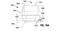
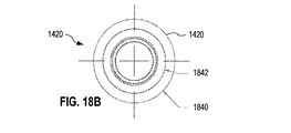
図18A〜図18Eは、位置決めアーム1402の1つの例示的な実施形態をさらに詳細に示す図である。図18A〜図18Cは、ソケット1420の直交する側面図を示し、図18Dおよび18Eは、シリンダ1430の直交する側面図を示している。図18A〜図18Eは、一緒に見るのが最適である。
18A-18E illustrate one exemplary embodiment of the
ソケット1420は、部分1810、1812、および1814を含む。部分1810および1812は、部分1810および1812が直径1860のシリンダ1430を保持することができるように、直径1822のカニューレ挿入部を含む。部分1814は、頭部1412が着座するように構成される。部分1814と頭部1412とが協働してジョイント1406を形成する。図18A〜図18Eに示された例では、ジョイント1406の角度範囲は、ファスナ1410の長手方向軸に直交する任意の方向において30度(円錐状)である。しかしながら、部分1814および/または頭部1412は、本明細書の範囲から逸脱することなく、ジョイント1406の異なる角度範囲を提供するように変更されてもよい。例えば、ジョイント1406の角度範囲は、ジョイント610について図7C〜図7Eを参照して説明した通りであってもよい。
直径1820、1822、および1824は、例えば、それぞれ0.5480インチ、0.4205インチおよび0.2929インチである。寸法1826、1828、1830、1832、1834および1836は、例えば、それぞれ0.1815インチ、0.1165インチ、0.2020インチ、0.0700インチ、0.0950インチおよび0.0370インチである。直径1840および1842は、例えば、それぞれ0.5480インチおよび0.4205インチである。曲率半径1846、1848、および1849は、例えば、それぞれ0.2349インチ、0.1465インチ、および0.0250インチである(インチの単位は、[]×2.4=[]mmの換算表に従ってミリメートルに換算することができます。)。角度1844は、例えば、19.00度である。
シリンダ1430は、長さ1850を有する。長さ1850は、シリンダ1430が不必要に長くなく、コネクタ1404と結合するために患者170の外側に十分な長さを有するように、70ミリメートルと120ミリメートルの間の範囲であり得る。一例では、長さ1850は4.0インチである。寸法1852および1854は、それぞれ3.5インチおよび0.5インチとすることができる。ねじ1434は、例えば、5/16−24NFねじである。一例では、直径1860および1862はそれぞれ0.4205インチおよび0.2529である。
The
本明細書の範囲から逸脱することなく、ソケット1420およびシリンダ1430の実際の寸法は、ここに列挙されたものとは異なっていてもよい。
Without departing from the scope of this specification, the actual dimensions of
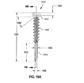
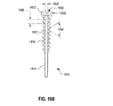
図19A〜図19Cは、ファスナ1410の例示的な実施形態をさらに詳細に示す図である。図19Aは、ファスナ1410の側面図である。図19Bは、図19Aの線19B−19Bに沿ったファスナ1410の断面図である。図19Cは、ファスナ1410の上面図である。図19A〜図19Cは、一緒に見るのが最適である。
19A-19C illustrate an exemplary embodiment of
頭部1412は、ファスナ1410を椎弓根176に固定するために使用される、ねじ回し1470などのツールを受け入れるための六角形のくぼみ1910を有する。本明細書の範囲から逸脱することなく、くぼみ1910は異なる形状を有してもよく、および/または異なるツールと係合するような突起部であってもよい。任意選択で、ファスナ1410は、例えばファスナ1410をガイドワイヤの上で挿入するため、または、ガイドワイヤが続いて椎弓根ねじの挿入のために使用され得るようにファスナ1410が椎弓根176内の所定の位置にあるときに、カニューレ挿入部1912を通じてガイドワイヤを挿入するために使用されるカニューレ挿入部1912を有する。カニューレ挿入型のファスナ1410が供給される単椎弓根標的化システム1400の実施形態は、カニューレ挿入部1912に挿入されたときにカニューレ挿入部1912に異物が入るのを防止するプラグをさらに供給され得る。
The
寸法1920、1922、1924、1926、1928、および1940は、例えば、それぞれ、1.7268インチ、0.6524インチ、0.1000インチ、0.0865インチ、0.0630インチ、および0.1024インチである。曲率半径1930は0.1465インチであってもよい(インチの単位は、[]×2.4=[]mmの換算表に従ってミリメートルに換算することができます。)。角度1942、1944、1946は、例えば、それぞれ64度、38度、1.0度である。本明細書の範囲から逸脱することなく、ファスナ1410の実際の寸法は、ここに列挙された寸法とは異なってもよい。
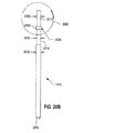
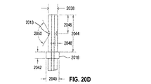
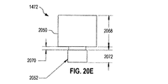
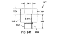
図20A〜図20Hは、ねじ回し1470の例示的な実施形態をさらに詳細に示す図である。図20A〜図20Cは、ねじ回し1470の直交する側面図である。図20Dは、図20Bに示されるねじ回し1470の一部2090の拡大図である。図20E〜図20Gは、ロックボルト1472の直交する側面図である。図20Hは、ロックボルト1472の斜視図である。図20A〜図20Hは、一緒に見るのが最適である。
20A-20H illustrate an exemplary embodiment of the
ねじ回し1470は、(a)部分1474、(b)六角形の頭部2010、(c)部分1474に隣接する小径部分2014、(d)部分2014に隣接する大径部分2018、および(e)頭部2010から最も遠いアクチュエータ部分2012を含む。部分2014は、ロックボルト1472を保持する。ロックボルト1472は、部分2014の周りで自由に回転できるが、フランジ1473を越えて摺動することはできない。部分2018は、ロックボルト1472がねじ回し1470から外れないことを保証するストッパである。アクチュエータ部分2012は、ねじ回し1470がロックボルト1472を使用してシリンダ1430にロックされたときに、ツールと係合してファスナ1410を椎弓根176に駆動するように構成された2つのへこみ2013を含む。
寸法2020、2022、1476、2026、2028、2030、2032、2034、2038、2040、2042、2044、2046、2048は、それぞれ、例えば、5.7085インチ、0.8000インチ、3.8335インチ、0.0720インチ、0.1860インチ、0.2105インチ、0.2080インチ、0.2475インチ、0.2105インチ、0.3000インチ、0.1500インチ、0.8530インチ、0.4250インチ、および0.0400インチである(以下、インチの単位は、[]×2.4=[]mmの換算表に従ってミリメートルに換算することができます。)。角度2050は、例えば、120度である。
ロックボルト1472は、部分2050および2052を含む。部分2050は、ロックボルト1472を作動させるためのハンドホールドを提供する。部分2052は、ねじ1434と係合する雄ねじを有する。ロックボルト1472は、カニューレ挿入部2054および2056を有する。カニューレ挿入部2054は、部分2018の少なくとも一部を収容するような大きさである。カニューレ挿入部2056は、部分2014を収容するような大きさである。直径2060、2062、2074、2076は、例えば、それぞれ0.6250インチ、0.3125インチ、0.3020インチ、および0.2140インチである。部分2052は、5/16−24NFねじを有してもよい。寸法2064、2066、2068、2070、および2072は、例えば、それぞれ0.2000インチ、0.5500インチ、0.5000インチ、0.0500インチ、および0.2000インチである(以下、インチの単位は、[]×2.4=[]mmの換算表に従ってミリメートルに換算することができます。)。
本明細書の範囲から逸脱することなく、ねじ回し1470の実際の寸法は、ここに列挙された寸法と異なっていてもよい。
Without departing from the scope of this specification, the actual dimensions of
図21Aおよび21Bは、ロックドライバ1480の例示的な実施形態をさらに詳細に示す図である。図21Aは、ロックドライバ2180の側面図である。図21Bは、図21Aに示されたロックドライバ2180の一部2190の拡大図である。図21Aおよび図21Bは、一緒に見るのが最適である。
21A and 21B are diagrams illustrating an exemplary embodiment of the
ロックドライバ1480は、(a)丸い頭部2140を有する部分2112、(b)部分2112に隣接する部分2110、(c)5/16−24NFねじを有してもよいねじ部分1482、および(d)作動部分2116を含む。丸い頭部2140は、ねじ1482がシリンダ1430のねじ1434内に十分にねじ込まれると、頭部1412に圧力を加えるように構成される。作動部分2116は、手で作動させることができ、またはロックドライバ1480を作動させるためのツールと係合するように構成された2つのへこみ2118を含むことができる。
The
寸法2120、2122、2124、2126、2628、2130および2138は、例えば、それぞれ5.0660インチ、3.6200インチ、0.3000インチ、0.8930インチ、0.2430インチ、0.4680インチおよび0.0400インチである。直径2132、2134および2136は、例えば、それぞれ0.2430インチ、0.3125インチおよび0.2105インチである(以下、インチの単位は、[]×2.4=[]mmの換算表に従ってミリメートルに換算することができます。)。丸い頭部2140は、0.1250インチの曲率半径を有することができる。
本明細書の範囲から逸脱することなく、ロックドライバ1480の実際の寸法は、ここに列挙したものとは異なっていてもよい。
Without departing from the scope of this specification, the actual dimensions of the
図22A〜図22Fは、カプラ1490の1つの例示的な実施形態をさらに詳細に示す図である。図22A〜図22Cは、カプラ1490の直交する側面図である。図22Dはカプラ1490の斜視図である。図22Eおよび図22Fは、ロックファスナ1497の直交する側面図である。図22A〜図22Fは、一緒に見るのが最適である。
22A-22F illustrate one exemplary embodiment of
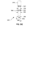
カプラ1490は、雌ねじ2230を有するレセプタクル2210を含む。ロックファスナ1497は、ねじ部分2252および作動部分2250を含む。ねじ部分2252は、レセプタクル2210内にねじ込まれて雌ねじ2230と係合するように構成される。雌ねじ2230およびねじ切りされた部分2252のねじは、1/4−20NCであってもよい。リング1492は、外径2220および内径2222を有する。直径2220および2222は、それぞれ1.1125インチおよび0.9700インチであってもよい。突起部1496は、例えば0.1875インチの半径2224のボールであってもよい。寸法2226、2228、2232、2234、および2238は、例えば、それぞれ0.3750インチ、0.2076インチ、0.4000インチ、0.4000インチ、0.1755インチである。寸法2270、2272、2274は、例えば、それぞれ0.4150インチ、0.0960インチ、および0.1400インチである。直径2260、2262、2264は、例えば、それぞれ0.3750インチ、0.2500インチ、および0.1680インチである(以下、インチの単位は、[]×2.4=[]mmの換算表に従ってミリメートルに換算することができます。)。角度2297は90度であってもよい。本明細書の範囲から逸脱することなく、カプラ1490の実際の寸法は、ここに列挙されたものと異なる場合があり、リング1492上のレセプタクル2210の位置、形状、および/またはサイズは、図22A〜図22Dに示されたものと異なっていてもよい。さらに、ロックファスナ1497は、止めねじのような異なるタイプのファスナで置き換えてもよい。
図23A〜図23Dは、1つの例示的な管状の開創器2300を示す図である。管状の開創器2300は、脊椎手術装置1493の実施形態である。一例では、管状の開創器2300は複数回使用することが意図され、使用の間に容易に洗浄できる材料、例えば金属で作られる。他の例では、管状の開創器2300は、一回の使用を意図した使い捨て装置である。この例では、管状の開創器2300は、デルリンのようなプラスチック、他の機械加工可能なポリマー、または成形可能なポリマーで作られ得る。
23A-23D illustrate one
管状の開創器2300は、カプラ1490によって受け入れられるように構成される。管状の開創器2300は、管状の開創器2300がリング1492を通って滑ることを防止するリップを形成するテーパ部分2314を含む。管状の開創器は、さらに、直線状円筒部分2310およびテーパ部分2312を含む。テーパ部分2312は、管状の開創器2300を患者170へ挿入するのを容易にする働きをする。カニューレ挿入部2316は、管状の開創器2300を通過し、外科医180が手術部位270にアクセスして手術するための経路を提供する。カニューレ挿入部2316は、患者170の組織を拡張するために使用される拡張器の形状およびサイズに適合するように構成されてもよい。この拡張器は、例えば、患者170の組織を段階的に拡張するために使用される一連の拡張器の最大拡張器である。本明細書の範囲から逸脱することなく、テーパ部分2314を省略してもよく、または直線円筒部分2310と同じ内径および外径を有する直線部分で置き換えてもよい。
寸法2330、2332、2334、および2336は、例えば、2.2940インチ、1.7317インチ、0.4250インチおよび0.1373インチである。直径2322および2320は、例えば、それぞれ1.1250インチおよび0.8661インチである(以下、インチの単位は、[]×2.4=[]mmの換算表に従ってミリメートルに換算することができます。)。テーパ角2324および2326は、例えば、60度および1度である。他の実施形態では、寸法2330は30〜90ミリメートル(例えば50〜60ミリメートル)の範囲内であり、直径2322は15〜40ミリメートル(例えば20〜30ミリメートルまたは16〜26ミリメートル)の範囲内であり、直径2320は、直径2322よりも約1〜3ミリメートル小さい。本明細書の範囲から逸脱することなく、管状の開創器2300の実際の寸法は、ここに列挙された寸法とは異なっていてもよい。
図24は、入れ子式ジョイント2420を備えたマニピュレータ2410を含む、後方脊椎手術用の1つの例示的な単椎弓根標的化システム2400を示す図である。単椎弓根標的化システム2400は単椎弓根標的化システム400の実施形態であり、マニピュレータ2410はマニピュレータ410の実施形態である。単椎弓根標的化システム2400は、単椎弓根標的化システム490の実施形態でもあり、マニピュレータ2410は、経皮椎弓根ねじ212の一実施形態であり、コネクタ460の一部である。単椎弓根標的化システム2400は、方法500、501、502および503のいずれかを実施するために使用され得る。
FIG. 24 illustrates one exemplary single
マニピュレータ2410は、少なくとも2つのコネクタ431を含む。図24には示されていないが、マニピュレータ2410は、本明細書の範囲から逸脱することなく、3つ以上のコネクタ431を実装することができる。マニピュレータ2410のコネクタ440は、ジョイント構成要素422を入れ子式ジョイント構成要素2422として実装し、コネクタ440に隣接するコネクタ431は、入れ子式ジョイント構成要素2432を実装する。入れ子式ジョイント構成要素2422および2432は、嵌合するように構成され、入れ子式ジョイント2420を形成する。単椎弓根標的化システム490の文脈において、これは、コネクタ460の他のジョイント構成要素472と嵌合して入れ子式ジョイント2420を形成するサブコネクタ462のジョイント構成要素472に対応する。入れ子式ジョイント2420は、マニピュレータ2410のリーチを変更することを可能にする。したがって、マニピュレータ2410は、柔軟なリーチおよび/または長いリーチが必要な状況において特に有用である。1つの使用シナリオでは、入れ子式ジョイントを使用して、手術部位270を対側で標的とする。
The manipulator 2410 includes at least two
比較のために、入れ子式ジョイント2420を実装していない単椎弓根標的化システム400(または490)の実施形態は、代わりに、異なるそれぞれのリーチ、および/または、異なるそれぞれのリーチを有する1つまたは複数のコネクタ431のいくつか、を有する複数のコネクタ440(または460)を含むキットとしてユーザに提供されてもよい。
For comparison, an embodiment of a single pedicle targeting system 400 (or 490) that does not implement a telescoping joint 2420 instead has a different respective reach and / or a different
図56〜図59を参照して以下にさらに詳細に説明するように、単椎弓根標的化システム2400は、それぞれが単椎弓根標的化システム2400と同じ機能性を有するが、脊椎172の異なる構造または患者170の骨盤に固定され得る、脊椎固定式標的化システムに容易に拡張される。このような脊椎固定式標的化システムは、患者170の頸椎、胸椎、および/または腰椎の後方脊椎手術において使用され得る。
As described in more detail below with reference to FIGS. 56-59, the single
図25は、組み立てられたときに、(a)球ジョイント610、(b)少なくとも並進自由度を有するジョイント630、(c)脊椎手術装置650の球ジョイント構成要素652と嵌合するように構成された球ジョイント構成要素622、および(d)入れ子式ジョイント2520を形成する単椎弓根標的化システム2500の実施形態を示す図である。入れ子式ジョイント2520は、入れ子式ジョイント2420の実施形態である。単椎弓根標的化システム2500は、単椎弓根標的化システム2400の実施形態である。単椎弓根標的化システム2500は、方法500、501、502および503のいずれかを実施するために使用され得る。単椎弓根標的化システム2500は、コネクタ640が、嵌合して入れ子式ジョイント2520を形成するように構成された2つのコネクタ2542および2544を有するコネクタ2540によって置き換えられる点を除いて、単椎弓根標的化システム600と同様である。入れ子式ジョイント2520は、方向2548に沿ったコネクタ2540の長さの変更を可能にし、それによって単椎弓根標的化システム2500のリーチの変更を容易にする。コネクタ2544はマニピュレータ2430のコネクタ440の実施形態であり、コネクタ2542はマニピュレータ2430の隣接するコネクタ431の実施形態である。
FIG. 25 is configured to mate with (a) a ball joint 610, (b) a joint 630 having at least translational freedom, and (c) a ball
任意選択で、コネクタ2540は、所望の構成で入れ子式ジョイント2520をロックするために係合され得るロック装置2546を含む。ロック装置2546は、マニピュレータ2410の入れ子式ジョイント2420をロックするように構成されたロック装置424の実施形態である。
Optionally,
本明細書の範囲から逸脱することなく、単椎弓根標的化システム2500のファスナ110、ジョイント610、および位置決めアーム620は、経皮椎弓根ねじ212または経皮椎弓根ねじ670に置き換えられてもよい。また、本明細書の範囲から逸脱することなく、コネクタ2540は、手術部位270を標的とするために、第三者の経皮椎弓根ねじおよび第三者の脊椎手術装置650と結合するように構成された独立型アイテムとして供給されてもよい。コネクタ2540は、コネクタ460の実施形態である。コネクタ2540は、コネクタ200の実施形態でもある。
The
図56〜図59を参照して以下にさらに詳細に説明するように、単椎弓根標的化システム2500は、それぞれが単椎弓根標的化システム2500と同じ機能性を有するが、脊椎172の異なる構造または患者170の骨盤に固定され得る、脊椎固定式標的化システムに容易に拡張される。このような脊椎固定式標的化システムは、患者170の頸椎、胸椎、および/または腰椎の後方脊椎手術において使用され得る。
As described in more detail below with reference to FIGS. 56-59, the single
図26は、追加の回転ジョイント2646を含む単椎弓根標的化システム2500の拡張である1つの例示的な単椎弓根標的化システム2600を示す図である。単椎弓根標的化システム2500と比較して、コネクタ2540がコネクタ2640に置き換えられている。コネクタ2640は、コネクタ2542が回転ジョイント2648を含むコネクタ2642に置き換えられていることを除いて、コネクタ2540と同様である。回転ジョイント2648は、1つ、2つ、または3つの回転自由度を有することができる。回転ジョイント2648は、コネクタ2640の角度の変更を可能にし、したがって外科医180に、所望の軌道に沿って手術部位270を標的とする追加の柔軟性を提供する。任意選択で、単椎弓根標的化システム2600は、所望の構成で回転ジョイント2646をロックするために係合され得るロック装置2648を含む。単椎弓根標的化システム2600は、方法500、501、502および503のいずれかを実施するために使用され得る。
FIG. 26 is a diagram illustrating one exemplary single
本明細書の範囲から逸脱することなく、単椎弓根標的化システム2600のファスナ110、ジョイント610、および位置決めアーム620は、経皮椎弓根ねじ212または経皮椎弓根ねじ670に置き換えてもよい。また、本明細書の範囲から逸脱することなく、コネクタ2640は、手術部位270を標的とするために、第三者の経皮椎弓根ねじおよび第三者の脊椎手術装置650と結合するように構成された独立型アイテムとして供給されてもよい。コネクタ2640は、コネクタ460およびコネクタ200の実施形態である。
The
図56〜図59を参照して以下にさらに詳細に説明するように、単椎弓根標的化システム2600は、それぞれが単椎弓根標的化システム2600と同じ機能性を有するが、脊椎172の異なる構造または患者170の骨盤に固定され得る、脊椎固定式標的化システムに容易に拡張される。このような脊椎固定式標的化システムは、患者170の頸椎、胸椎、および/または腰椎の後方脊椎手術において使用され得る。
As described in more detail below with reference to FIGS. 56-59, the single
図27は、脊椎手術装置2750と強固に結合するように構成された後方脊椎手術のための1つの例示的な単椎弓根標的化システム2700を示す図である。単椎弓根標的化システム2700は、(a)マニピュレータ2410がマニピュレータ2710に置き換えられ、(b)マニピュレータ2710が脊椎手術装置2750と強固に結合するように構成されていることを除いて、単椎弓根標的化システム2400と同様である。特定の実施形態では、単椎弓根標的化システム2700は、脊椎手術装置2750を含む。単椎弓根標的化システム2700は、方法500、501、502および503のいずれかを実施するために使用され得る。
FIG. 27 illustrates one exemplary single
マニピュレータ2710は、マニピュレータ2710と同様であり、少なくとも2つのコネクタ431を実装する。図27には示されていないが、マニピュレータ2710は、本明細書の範囲から逸脱することなく、2つ以上のコネクタ431を実装することができる。マニピュレータ2410と比較して、マニピュレータ2710は、コネクタ440をコネクタ2730で置き換える。コネクタ2730は、ジョイント構成要素122が、脊椎手術装置2750のカプラ2752と強固に結合するように構成された剛性カプラ2722によって置き換えられている点を除いて、コネクタ440と同様である。マニピュレータ2710は、2つのジョイント420を含み、ファスナ110を有するジョイント430を形成する。ジョイント420およびジョイント430は、組み立てられると、単椎弓根標的化システム2700が椎弓根176に対する脊椎手術装置2750の3並進自由度および3回転自由度を提供するように構成される。
The
一実施形態では、ジョイント430は球ジョイントであり、一方のジョイント420は球ジョイントであり、他方のジョイント420は少なくとも1つの並進自由度を有し、任意選択でさらに他の自由度を有する。 In one embodiment, joint 430 is a spherical joint, one joint 420 is a spherical joint, and the other joint 420 has at least one translational degree of freedom, and optionally has other degrees of freedom.
本明細書の範囲から逸脱することなく、ファスナ110およびファスナ110に結合されたコネクタ431は、経皮椎弓根ねじ212または経皮椎弓根ねじ670によって置き換えられてもよい。
Without departing from the scope herein,
図56〜図59を参照して以下にさらに詳細に説明するように、単椎弓根標的化システム2700は、それぞれが単椎弓根標的化システム2700と同じ機能性を有するが、脊椎172の異なる構造または患者170の骨盤に固定され得る、脊椎固定式標的化システムに容易に拡張される。このような脊椎固定式標的化システムは、患者170の頸椎、胸椎、および/または腰椎の後方脊椎手術において使用され得る。
As described in more detail below with reference to FIGS. 56-59, the single
また、図28Aおよび図28Bは、脊椎手術装置2750と強固に結合するように構成された1つの例示的な単椎弓根標的化システム2800を示す図である。単椎弓根標的化システム2800は、単椎弓根標的化システム2700の実施形態である。単椎弓根標的化システム2800は、脊椎手術装置2750を含み得る。図28Aおよび図28Bは、単椎弓根標的化システム2800の2つの異なる状態を示す。図28Aおよび図28Bは一緒に見るのが最適である。
FIGS. 28A and 28B also illustrate one exemplary single
単椎弓根標的化システム2800は、ファスナ110と、位置決めアーム2820と、コネクタ2730とを含む。ファスナ110および位置決めアーム2820は、ファスナ110および位置決めアーム620について図6Aを参照して説明したように、球ジョイント610を介して互いに結合するように構成されている。位置決めアーム2820およびコネクタ2730は、位置決めアーム620およびコネクタ640について図6Aを参照して説明したように、ジョイント630を介して互いに結合するように構成される。コネクタ2730は、図27を参照して説明したように、脊椎手術装置2750と強固に結合するように構成される。任意選択で、単椎弓根標的化システム2800は、ロック装置692および694の一方または両方を含む。
Single
位置決めアーム2820は、球ジョイント2846を介して互いに結合するように構成された2つのコネクタ2830および2840を含む。任意選択で、単椎弓根標的化システム2800は、係合して球ジョイント2846を所望の構成にロックすることができるロック装置2848を含む。球ジョイント610、球ジョイント2846、およびジョイント630は協働して、椎弓根176に対する脊椎手術装置2750の3並進自由度および3回転自由度を提供する。
The
図28Aは、平行コネクタ2830および2840を有する直線状の位置決めアーム2820を示している。図28Bは、コネクタ2830および2840が互いに対してある角度をなして曲げた状態の位置決めアーム2820を示している。
FIG. 28A shows a
一実施形態では、位置決めアーム2820は、位置決めアーム2820の全長を貫通するカニューレ挿入部2824を含み、少なくともコネクタ2830および2840が図28Aに示すように平行であるときに、ファスナ110がカニューレ挿入部2824を介して係合され得る。
In one embodiment,
図56〜図59を参照して以下にさらに詳細に説明するように、単椎弓根標的化システム2800は、それぞれが単椎弓根標的化システム2800と同じ機能性を有するが、脊椎172の異なる構造または患者170の骨盤に固定され得る、脊椎固定式標的化システムに容易に拡張される。このような脊椎固定式標的化システムは、患者170の頸椎、胸椎、および/または腰椎の後方脊椎手術において使用され得る。
As described in more detail below with reference to FIGS. 56-59, the single
図29A〜図29Cは、経皮椎弓根ねじ2902に基づく、後方脊椎手術のための1つの例示的な単椎弓根標的化システム2900を示す図である。単椎弓根標的化システム2900は、単椎弓根標的化システム602の実施形態であり、経皮椎弓根ねじ2902は、経皮椎弓根ねじ212の実施形態である。単椎弓根標的化システム2900は、方法500、501、502および503のいずれかを実施するために使用され得る。図29Aおよび図29Bのそれぞれは、組み立てられた形態で椎弓根176に挿入され、対側の作業方向から外科手術部位270を標的とするために脊椎手術装置1493と結合された単椎弓根標的化システム2900を示している。図29Cは、単椎弓根標的化システム2900を分解図で示している。図29A〜図29Cは、一緒に見るのが最適である。
FIGS. 29A-29C illustrate one exemplary single
図29A〜図29Cに示す実施形態では、経皮椎弓根ねじ2902は、StrykerによるES2(登録商標) Spinal Systemの経皮椎弓根ねじと同様である。しかしながら、本明細書の範囲から逸脱することなく、経皮椎弓根ねじ2902は、他の市販の経皮椎弓根ねじ、または特注品であってもよい。経皮椎弓根ねじ212として実装するのに適した経皮椎弓根ねじを供給する例示的なベンダーには、Stryker、DePuy Synthes、NuVasive、Globus、K2 Medical、Medtronic、Biomet、およびZimmer Spineが含まれるが、これらに限定されない。経皮椎弓根ねじ2902は、(a)椎弓根176にねじ込むための椎弓根ねじ2910、(b)椎弓根ねじ2910の頭部2912と球ジョイント2915を形成するソケット2920、(c)ソケット2920との脆弱な接続のみを有する2つのブレイクオフブレード2930、および(d)安定化クリップ2936を含む。ブレイクオフブレード2930は、取り外し可能なガイド延長部240の実施形態を形成し、ソケット2920はソケット230の実施形態であり、椎弓根ねじ2910は椎弓根ねじ220の実施形態であり、球ジョイント2915はジョイント680の実施形態である。球ジョイント2915は、ジョイント610について図7C〜図7Eを参照して説明したような角度範囲を有することができる。本明細書の範囲から逸脱することなく、安定化クリップを必要としない第三者の経皮椎弓根ねじに基づく単椎弓根標的化システム2900の実施形態に安定化クリップ2936を含める必要はない。同様に、単椎弓根標的化システム2900は、経皮椎弓根ねじと協働するように構成されてもよく、ブレイクオフブレード2930は、取り外し可能なガイド延長部240の他の実装形態に置き換えられる。
In the embodiment shown in FIGS. 29A-29C, the
ブレイクオフブレード2930は、必要でなくなったときにソケット2920から切り離されてもよい。安定化クリップ2936は、ブレイクオフブレード2930がソケット2920から不用意に取り外されるのを防止するために、ブレイクオフブレード2930のそれぞれに取り付けてブレイクオフブレード2930の相対位置を安定させるように構成されたリップを有する。クリップ2936は、ブレイクオフブレード2930から取り外し可能である。クリップ2936は、ブレイクオフブレード2930に面するバネ付勢突起部を有する。ブレイクオフブレード2930は、ソケット2920からいくつかの異なる距離に配置された整合へこみ2932を有し、クリップ2936はソケット2920からのこれらの異なる距離でブレイクオフブレード2930と安定して結合することができる。本明細書の範囲から逸脱することなく、ブレイクオフブレード2930は、図29A〜図29Cに示すものとは異なるように構成することができ、および/または、クリップ2936は、ブレイクオフブレード2930と接合するように構成された特徴を備えた他の形態の安定化クランプと置き換えて、ブレイクオフブレード2930がソケット2920から不用意に取り外されるのを防止することができる。1つのそのような例では、経皮椎弓根ねじ2902は、3つ以上のブレイクオフブレードを含み、クリップ2936は、これらのブレイクオフブレードの相対位置を安定させるクランプで置き換えられる。
Break-
経皮椎弓根ねじ2902は、少なくともブレイクオフブレード2930上に配置された雌ねじ2922を有する。椎弓根ねじ2910の頭部2912には、ブレイクオフブレード2930によって形成されたカニューレ挿入部を介してツールを用いてアクセスすることができる。一実施形態では、椎弓根ねじ2910は、例えばガイドワイヤを収容するようにカニューレ挿入される。他の実施形態では、椎弓根ねじ2910はカニューレ挿入されない。
経皮椎弓根ねじ2902に加えて、単椎弓根標的化システム2900は、コネクタ2904を含む。コネクタ2904は、コネクタ660およびコネクタ200の実施形態である。コネクタ2904は、経皮椎弓根ねじ2902と結合することを除いて、コネクタ1404と同様である。コネクタ2904は、2つのクランプ部品2940および2949を含む。クランプ部品2940は溝2942を有し、クランプ部品2949は溝2962を有する。クランプ部品2940および2949は、ブレイクオフブレード2930の周りで(図29Bに示すように)、またはクリップ2936の周りで(図29Aに示すように)、溝2942および2962を用いて一緒にされ、円筒形ジョイント2908を形成するように構成される。円筒形ジョイント2908は、ジョイント630の実施形態である。一実装形態では、コネクタ2904は、ブレイクオフブレード2930の長さに沿った任意の位置で、例えばクリップ2936よりもソケット2920に近い位置で、ブレイクオフブレード2930上に取り付けられてもよい。クランプ部品2940および2949のそれぞれのレセプタクル2944および2952は、カプラ1490の突起部1496と嵌合して球ジョイント2995を形成するように構成される。カプラ1490は、脊椎手術装置1493と取り外し可能に結合するように構成される。
In addition to the
図29A〜図29Cに示すように、コネクタ2904は、手術部位270を対側で標的とするのに適した長さを有する。しかしながら、コネクタ2904は、本明細書の範囲から逸脱することなく、椎弓根176に隣接する脊椎部分において手術部位270を同側で標的とするように、図29A〜図29Cに示すよりも短くなっていてもよい。同様に、コネクタ2904は、より遠隔の手術部位270を標的とするように、図29A〜図29Cに示すよりも長くなっていてもよい。
As shown in FIGS. 29A-29C, the
本明細書の範囲から逸脱することなく、コネクタ2904は、溝2942および2962の代わりに突起部を有し、突起部は、突起部1496の代わりにカプラ1490のレセプタクルと嵌合して球ジョイント2995を形成することができる。
Without departing from the scope of this specification,
単椎弓根標的化システム2900は、ブレイクオフブレード2930の間の経皮椎弓根ねじ2902に挿入され、雌ねじ2922と係合して、ソケット2920を介して頭部2912を押すことができるロックドライバ2980をさらに含む。ロックドライバ2980は、ロックドライバ2980が雌ねじ2922にねじ込まれ得るように、雄ねじ2982を有する。雌ねじ2922と雄ねじ2982との間の接触は、頭部2912とロックドライバ2980との間の圧力と協働して、球ジョイント2915をロックする。ロックドライバ2980は、ロック装置693の実施形態である。図29A〜図29Cには示されていないが、単椎弓根標的化システム2900は、ロックドライバ2980を作動させるためのツールを含むことができる。
A single
単椎弓根標的化システム2900はまた、クランプ部品2940および2949のうちの1つを通して挿入され、クランプ部品2940および2949のうちの他の1つにねじ込まれ、ジョイント2908および2995の両方をロックするように、クランプ部品2940および2949をブレイクオフブレード2930および突起部1496上でともに締め付けることができる2つのロックファスナ2905も含む。ロックファスナ2905は、ロック装置694および696を実装し、ロックファスナ1405と同様である。クランプ部品2949は、その間にヒンジ2955を有する2つのクランプサブ部品2950および2960を含む。クランプサブ部品2950は、レセプタクル2952を含む。クランプサブ部品2960は、溝2962を含む。ヒンジ2955は、ジョイント2908および2995の相互に独立したロックを容易にする。
Single
本明細書の範囲から逸脱することなく、ロックファスナ2905は、ロックファスナ1405についてさらに詳細に説明したように、指掛け部の使用とは対照的にツールによる作動のために構成されてもよく、および/または、ねじまたは他のくぼんだねじとしてもよい。同様に、ロックファスナ2905は、ロックファスナ1405についてさらに詳細に説明したように、斜めの角度でコネクタ2904を通るように向けられていてもよい。さらに、ロックファスナ2905は、本明細書の範囲から逸脱することなく、ロックファスナ1405についてさらに詳細に説明したように、患者170から全体的に反対側を向く面からコネクタ2904にアクセスすることができる。
Without departing from the scope herein, the
カプラ1490の接続アーム1494は、図14A〜図14Cを参照して単椎弓根標的化システム1400について説明したように、単椎弓根標的化システム2900に対して同じ利点を提供する90度の角度を有する。本明細書の範囲から逸脱することなく、リング1492は、図29A〜図29Cに示された脊椎手術装置1493とは異なる脊椎手術装置と結合するように構成された異なる形状の要素と置き換えることができる。
The connecting
単椎弓根標的化システム2900は、単椎弓根標的化システム1400について上述したように、脊椎手術装置1493の長手方向軸に対するカプラ1490の2つの異なる方向を利用して、手術部位270を対側または同側で標的とすることができる。
The single
他の実施形態では、突起部1496は、接続アーム1494を介して脊椎手術装置1493に恒久的にかつ堅固に結合され、一体化されたカプラ脊椎手術装置を形成する。1つの例示的なシナリオでは、この一体化されたカプラ脊椎手術装置の2つの異なる実施形態が外科医180に供給され、同側および対側の処置の両方が可能となる。これらの2つの異なる実施形態は、上述したカプラ1490の2つの可能な向きと同様である。
In other embodiments, the
単椎弓根標的化システム900および脊椎手術装置960について上述したように、単椎弓根標的化システム2900または脊椎手術装置1493の1つまたは複数の部分は、アンチグレアまたはグレア低減表面を有してもよい。
As described above for single
特定の実施形態では、単椎弓根標的化システム2900は、脊椎手術装置1493を含む。
In certain embodiments, the single
本明細書の範囲から逸脱することなく、コネクタ2904は、第三者の経皮椎弓根ねじ212および第三者の脊椎手術装置150と協働して手術部位270を標的とするように構成された独立型アイテムとして供給することができる。コネクタ2904は、コネクタ200の実施形態である。また、本明細書の範囲から逸脱することなく、単椎弓根標的化システム2900のコネクタ2904をクランプ940で置き換えることができ、単椎弓根標的化システム900のクランプ940をコネクタ2904で置き換えることができる。同様に、単椎弓根標的化システム2900は、脊椎手術装置1493およびカプラ1490の代わりに脊椎手術装置960を利用することができる。
Without departing from the scope herein, the
ES2(登録商標) Spinal Systemでは、経皮椎弓根ねじは、ブレイクオフブレードとクリップとの間の安定した結合のための4つの異なる位置を提供するへこみを有する。しかしながら、ブレイクオフブレード2930は、本明細書の範囲から逸脱することなく、異なる数のこのようなへこみ2932を有し、対応する数の安定した結合位置を提供することができる。例えば、ブレイクオフブレード2930は、少なくとも6個、10個、または15個のへこみ2932のような5組以上のへこみ2932を有し、5つ以上の安定した結合位置を提供することができる。
In the ES2® Spinal System, the percutaneous pedicle screw has a dent that provides four different positions for a stable bond between the break-off blade and the clip. However, the break-
図30A〜図30Cは、クランプ部品2940の例示的な実施形態をさらに詳細に示す図である。図30Aおよび図30Bは、クランプ部品2940の直交する側面図を示し、図30Cはクランプ部品2940を斜視図で示している。図30A〜図30Cは、一緒に見るのが最適である。
30A-30C are diagrams illustrating an exemplary embodiment of the
クランプ部品2940は、長さ3020、1つの断面寸法3030、および寸法3040、3042、および3044の全体である直交する断面寸法を有する。クランプ部品2940は、ロックファスナ2905に係合するように構成されたねじ穴3010を含む。溝2942は円筒形であり、円筒軸はクランプ部品2940の断面範囲3030のわずかに外側に配置される。これは、クランプ部品2940がブレイクオフブレード2930(またはクリップ2936)の周りでクランプサブ部品2960と一緒にされたときに、単にクランプ部品2940とクランプサブ部品2960との間に圧力を加えることとは対照的に、コネクタ2904がブレイクオフブレード2930(またはクリップ2936)に圧力を確実に加えるのを助ける。レセプタクル2944は球形である。球の中心は、クランプ部品2940が突起部1496の周りでクランプサブ部品2950と一緒にされたときに、単にクランプ部品2940とクランプサブ部品2950との間に圧力を加えることとは対照的に、コネクタ2904が突起部1496に圧力を確実に加えるのを助けるために、範囲3030のわずかに外側に配置される。
一実施形態では、ねじ穴3010は、1/4−20NCタイプであり、対応する各ロックファスナ2905は、対応する1/4−20NC雄ねじを有する。一実施形態では、寸法3020、3022、3024、3026、3028、3030、3040、3042、および3044は、それぞれ、2.4850インチ、1.7544インチ、0.5044インチ、2.1362インチ、0.3500インチ、0.3375インチ、0.3050インチ、0.1125インチおよび0.1125インチである。一実施形態では、曲率半径3032、3036、3038および3039は、0.2813インチ、0.1875インチ、0.1250インチ、および0.2500インチであり、角度3034は25度である。レセプタクル2944は、レセプタクル1444の開口部と同様の角度のある開口部を有してもよい。本明細書の範囲から逸脱することなく、クランプ部品2940の実際の寸法は、ここに列挙された寸法と異なっていてもよい。
In one embodiment, the threaded
本明細書の範囲から逸脱することなく、クランプ部品2940の実際の寸法は、ここに列挙された寸法と異なっていてもよい。
Without departing from the scope of this specification, the actual dimensions of the
図31A〜図31Cは、クランプサブ部品2950の1つの例示的な実施形態をさらに詳細に示す図である。図31Aおよび図31Bは、クランプサブ部品2950の直交する側面図を示し、図31Cは、クランプサブ部品2950を斜視図で示している。図31A〜図31Cは、一緒に見るのが最適である。
FIGS. 31A-31C illustrate one exemplary embodiment of the
クランプサブ部品2950は、クランプサブ部品2960の整合特徴と協働してヒンジ2955を形成するスロット3110および貫通穴3114を含む。クランプサブ部品2950はさらに、1つのロックファスナ2905を受け入れるように構成された貫通孔3112を含む。レセプタクル2952は球形である。球の中心は、クランプ部品2940が突起部1496の周りでクランプサブ部品2950と一緒にされたときに、単にクランプ部品2940とクランプサブ部品2950との間に圧力を加えることとは対照的に、コネクタ2904が突起部1496に圧力を確実に加えるのを助けるために、範囲3121のわずかに外側(範囲3122によって示されている)に配置される。クランプサブ部品2950は、レセプタクル2952内への傾斜した開口部3153を有する。
一実施形態では、寸法3120、3121、3122、3124、3126、3128、3130、3132、3134、および3146は、それぞれ、0.9746インチ、約0.34インチ、0.3500インチ、0.1130インチ、0.1156インチ、0.1350インチ、0.2500インチ、0.6156インチ、0.3000インチ、および0.1339インチである。一実施形態では、貫通孔3114の直径は0.1250インチである。一実施形態では、角度3144は25度である。曲率半径3138、3140および3142は、例えば、それぞれ0.1000インチ、0.1875インチおよび0.1250インチである(以下、インチの単位は、[]×2.4=[]mmの換算表に従ってミリメートルに換算することができます。)。本明細書の範囲から逸脱することなく、クランプサブ部品2950の実際の寸法は、ここに列挙されたものとは異なっていてもよい。
In one embodiment,
本明細書の範囲から逸脱することなく、クランプサブ部品2950の実際の寸法は、ここに列挙されたものとは異なっていてもよい。
Without departing from the scope herein, the actual dimensions of the
図32A〜図32Cは、クランプサブ部品2960の1つの例示的な実施形態をさらに詳細に示す図である。図32Aおよび図32Bは、クランプサブ部品2960の直交する側面図を示し、図32Cは、クランプサブ部品2960を斜視図で示している。図32A〜図32Cは、一緒に見るのが最適である。
FIGS. 32A-32C illustrate one exemplary embodiment of the
クランプサブ部品2960は、スロット3110と嵌合するように構成された貫通孔3211を有するブラケット3210と、クランプサブ部品2950の貫通孔3114と貫通孔3211の両方を貫通してヒンジ2955を形成するピンとを含む。クランプサブ部品2960はさらに、1つのロックファスナ2905を受け入れるように構成された貫通孔3212を含む。溝2962は、円筒形である。シリンダの中心は、クランプ部品2940がブレイクオフブレード2930(またはクリップ2936)の周りでクランプサブ部品2960と一緒にされたときに、単にクランプ部品2940とクランプサブ部品2960との間に圧力を加えることとは対照的に、コネクタ2904がブレイクオフブレード2930に圧力を確実に加えるのを助けるために、範囲3228のわずかに外側(クランプサブ部品1460について説明した)に配置され得る。
The
一実施形態では、寸法3220、3222、3224、3226、3228、3230、3232、および3234は、それぞれ、0.5300インチ、0.3050インチ、0.2500インチ、0.1250インチ、0.3375インチ、0.1688インチ、0.1294インチ、および0.7390インチである。一実施形態では、直径3236は0.1250インチである。一実施形態では、曲率半径3240および3242は、それぞれ0.2500インチおよび0.2813インチである。本明細書の範囲から逸脱することなく、クランプサブ部品2960の実際の寸法は、ここに列挙されたものとは異なっていてもよい。
In one embodiment,
本明細書の範囲から逸脱することなく、クランプサブ部品2960の実際の寸法は、ここに列挙されたものとは異なっていてもよい。
Without departing from the scope of this specification, the actual dimensions of the
図33A〜図33Cは、単椎弓根標的化システム2900の実施形態で使用するための例示的なロックドライバ3300を示しており、経皮椎弓根ねじ2902は、StrykerによるES2(登録商標) Spinal Systemの経皮椎弓根ねじである。ロックドライバ3300は、ロックドライバ2980の実施形態である。図33Aは、ロックドライバ3300の側面図を示す。図33Bは、図33Aに示されたロックドライバ3300の一部3390の拡大図である。部分3390は、作動部分2116と同様の作動部分3320を含む。図33Cは、図33Aに示されたロックドライバ3300の一部3392の拡大図である。部分3392は、結合部分3330を含む。図33A〜図33Cは、一緒に見るのが最適である。
FIGS. 33A-33C illustrate an
ロックドライバ3300は、球ジョイント2915をロックするように、ブレイクオフブレード2930の間の経皮椎弓根ねじ2902に挿入され、雌ねじ2922と係合して頭部2912に圧力を加えるように構成される。ロックドライバ3300は、ブレイクオフブレード2930の内側にぴったりと嵌合されるように構成された部分3310を含む。部分3310は、その全長3312に沿って一定の直径3352を有する。部分3310は、コネクタ2904および/または関連するロックファスナ2905によるブレイクオフブレード2930に対する圧力を妨げ、コネクタ2904をブレイクオフブレード2930(またはクリップ2936)上に締め付けるためにロックファスナ2905を使用するときに、ブレイクオフブレード2930の一方または両方の不用意な取り外しを防止する。ぴったりとした嵌合は、部分3310の直径3352が、ブレイクオフブレード2930によって形成されたカニューレ挿入部の内径に近いことによって保証される。
The
結合部分3330は、(a)頭部2912に接触するように構成された先端3332と、(b)雌ねじ2922と係合するように構成された雄ねじ2982とを含む。雄ねじ2982が雌ねじ2922内に十分にねじ込まれると、先端3332は頭部2912に圧力を加え、球ジョイント2915をロックする。
The
任意選択で、作動部分3320は、ツールと結合してロックドライバ3300を経皮椎弓根ねじ2902にねじ込むように構成された2つのへこみ3322を含む。あるいは、外科医180は、ロックドライバ3300を経皮椎弓根ねじ2902に手で締め付けることができる。
Optionally, the
寸法3312、3350、3354、3356、3358、3360、3362、3366、3368、および3370は、それぞれ、例えば、3.1795インチ、5.7070インチ、0.1250インチ、0.3450インチ、0.1500インチ、0.6360インチ、0.1432インチ、0.0400インチ、0.4250インチ、および0.9180インチである。直径3352、3364、3374、3376、3378、3380および3382は、例えば、それぞれ0.4000インチ、0.2100インチ、0.3680インチ、0.2850インチ、0.3880インチ、0.2850インチおよび0.2200インチである(以下、インチの単位は、[]×2.4=[]mmの換算表に従ってミリメートルに換算することができます。)。角度3372および3386は、それぞれ、例えば、120度および60度である。本明細書の範囲から逸脱することなく、ロックドライバ3300の実際の寸法は、ここに列挙したものとは異なっていてもよい。
本明細書の範囲から逸脱することなく、ロックドライバ3300は、Stryker、DePuy Synthes、NuVasive、Globus、K2 Medical、Medtronic、Biomet、およびZimmer Spineによって供給されるような他の経皮椎弓根ねじ2902と協働するように適合させてもよい。
Without departing from the scope of this specification, the
また、図34A〜図34Dは、角度付き接続アームを有する例示的な管状の開創器3400を示す図である。管状の開創器3400は、単椎弓根標的化システム100と結合して、ジョイント構成要素122と球ジョイントを形成するように構成される。管状の開創器3400は、管3410、角度付き接続アーム3420、および突起部3430を含む。接続アーム3420は、管3410を突起部3430に接続する。図34A〜図34Cは、管状の開創器3400の直交する側面図を示している。図34Dは、管状の開創器3400の斜視図である。図34A〜図34Cは、一緒に見るのが最適である。
FIGS. 34A-34D also illustrate an
接続アーム3420は、管3410に取り付けられた直線部分3422と、突起部3430に接続された直線部分3426と、直線部分3422と3426を接続する角度付き部分3424とを含む。
特定の実施形態では、接続アーム3420は、水平方向に対して上方へ角度を付けられており、水平方向は、管3410の長手方向軸3412に直交する平面内の方向を指す。これにより、接続アーム3420の上方へ角度を付けた実施形態は、接続アーム3420と患者170の組織との間で起こり得る干渉を低減するので、患者170に対する管3410の位置決めの柔軟性が向上する。接続アーム3420の上方角度は、角度付き部分3424および/または接続アーム3420が管3410に取り付けられる点において達成され得る。本明細書の範囲から逸脱することなく、接続アーム3420は、例えば、接続アーム3420が管3410に取り付けられる点に隣接して、1つまたは複数の追加の角度付き部分を含むことができる。
In certain embodiments, the connecting
直線部分3422は、水平方向に対して角度3470が付いており、直線部分3426は水平方向に対して角度3472が付いている。直線部分3422および3426は、長手方向軸3412に直交する平面上に投影されたときに、互いに対して角度3474が付く。一実施形態では、角度3470は、0度と90度の間の範囲にあり、例えば0度と60度の間の範囲にある。一実施形態では、角度3472は、0度と90度の間の範囲にあり、例えば、0度と60度の間の範囲である。一実施形態では、角度3474は、30度と135度との間の範囲にあり、例えば80度と100度との間の範囲にある。
The
代替的な実施形態では、接続アーム3420は、直線部分を含まないか、または1つの直線部分のみを含む。例えば、接続アーム3420は、角度付き部分3424のみによって構成されてもよく、角度付き部分3424は、(a)管3410および突起部3430に直接結合されるか、(b)さもなければ角度付き部分3424および直線状部分3422および3426の全体的におよぶ距離にまたがる。
In alternative embodiments, the connecting
管状の開創器3400は、脊椎手術装置150および650の実施形態であり、突起部3430は、ジョイント構成要素152および652の実施形態である。管状の開創器3400は、(a)図9および図10の脊椎手術装置960、(b)図14Aおよび図14Bの脊椎手術装置1490およびカプラ1409、および(C)図29A〜図29Cの脊椎手術装置1490およびカプラ1409と置き換えることができる。
本明細書の範囲から逸脱することなく、管3410は非円形の断面を有することができる。例えば、管3410の断面は、楕円形または卵形であってもよいし、または三角形、矩形、正方形、五角形、六角形、または八角形などの多角形の形状を有してもよい。さらに、管3410は、複数の分離可能な部品から構成されてもよい。このような実装形態の1つでは、複数の分離可能な部品のうちの1つは、例えば、管3410の形状および/またはサイズを変更するために、または管3410に窓を形成するために取り外し可能であり得る。図34Aおよび図34Bにはほぼ完全な球体であると示されているが、突起部3430は、本明細書の範囲から逸脱することなく、異なる形状を有してもよい。例えば、突起部3430は、球のより小さな部分であってもよい。
The
図35は、角度付き接続アームを有する他の例示的な管状の開創器3500を示す図である。管状の開創器3500は、管状の開創器3400の接続アーム3420の向きとは反対の、長手方向軸3412に対する向きで接続アーム3420を実装する以外は、管状の開創器3400と同様である。
FIG. 35 shows another
図34A〜図34Dおよび図35をまとめて参照すると、管状の開創器3400および3500のそれぞれは、マニピュレータ210と結合されると、手術部位270への画像ベースの前後画像経路の外側にマニピュレータ210および管状の開創器の両方のそれぞれの位置決めを可能にする。脊椎手術装置1490(管状の開創器として実装される)およびカプラ1409と比較すると、管状の開創器3400および3500は、リング1492およびファスナ1497がないため、患者170内で管をより柔軟に位置決めすることができる。外科医180は、所望の作業方向から手術部位270を最適な状態で標的とする2つの可能性のある方向のうちの適切な1つにカプラ1409を用いて脊椎手術装置1490(管状の開創器として実装される)を組み立てる代わりに、管状の開創器3400および3500のうちの適切な1つを選択して同じ目標を達成することができる。
Referring collectively to FIGS. 34A-34D and FIG. 35, each of the
図36は、単椎弓根標的化システム100とそれぞれ結合してジョイント構成要素122を有する球ジョイントを形成するように構成された2つのジョイント構成要素を有する例示的なデュアルモードの管状の開創器3600を示す図である。管状の開創器3600は、接続アームがデュアルモードの接続アーム3620に置き換えられている点を除いて、管状の開創器3400と同様である。デュアルモードの接続アーム3620は、管3410を、図36Aおよび図36Bに突起部3430(1)、3430(2)として示された突起部3430の2つの例に接続する。図36は、管状の開創器3600を、図34Cで用いられたものと同じ視野で示している。
FIG. 36 illustrates an exemplary dual mode tubular retractor having two joint components each configured to couple with the single
接続アーム3620は、直線部分3422と、直線部分3426(1)および3426(2)として示される直線部分3426の2つの例と、結合部3624とを含む。接続アーム3620は、管3410を(a)直線部分3426(1)を介して突起部3430(1)に接続し、(b)直線部分3426(2)を介して突起部3430(2)に接続する。直線部分3422、結合部3624の一部、および直線部分3426(1)は全体として、管状の開創器3400と同じ向きで接続アーム3420を実現する。同様に、直線部分3422、結合部3624の一部、および直線部分3426(2)は協働して、管状の開創器3500と同じ向きで接続アーム3420を実現する。したがって、接続アーム3620は、接続アーム3420のこれらの2つの向きの両方を同時に実現する。外科医180は、突起部3430(1)を利用して、管状の開創器3400の機能を達成することができ、または代わりに、突起部3430(2)を利用して、管状の開創器3500の機能を達成することができる。
管状の開創器3600は、脊椎手術装置150および650の実施形態である。管状の開創器3600は、(a)図9および図10の脊椎手術装置960、(b)図14Aおよび図14Bの脊椎手術装置1490およびカプラ1409、および(C)図29A〜図29Cの脊椎手術装置1490およびカプラ1409と置き換えることができる。
図37Aおよび37Bは、例示的な使用シナリオにおける管状の開創器3400および3500の2つの例示的な実施形態をそれぞれ示す図である。図37Aは、対側の作業方向から手術部位270を標的とするために単椎弓根標的化システム2900と結合された1つの例示的な管状の開創器3700を示している。図37Bは、対側の作業方向から手術部位270を標的とするために単椎弓根標的化システム2900と結合された1つの例示的な管状の開創器3702を示している。管状の開創器3700および3702は、それぞれ管状の開創器3500および3400の実施形態である。また、図37Aおよび図37Bは、一緒に見るのが最適である。
FIGS. 37A and 37B are diagrams illustrating two exemplary embodiments of
図37Aおよび37Bに構成されているように、管状の開創器3700および3702のそれぞれは、手術部位270への画像ベースの前後画像経路の外側にコネクタ2904および管状の開創器の両方のそれぞれの位置決めを可能にする。管状の開創器3700および3702のそれぞれにおいて、直線部分3426は、水平方向に対して上方へ角度が付けられている。これにより、接続アーム3420と患者170の組織との間で起こり得る干渉が低減され、したがって、水平接続アームを有する管状の開創器と比較して、管状の開創器3700および3702の位置決めの柔軟性が改善される。
As configured in FIGS. 37A and 37B, each of the
管状の開創器3700および3702は、脊椎手術装置150および650の実施形態である。管状の開創器3700および3702は、(a)図9および図10の脊椎手術装置960、(b)図14Aおよび図14Bの脊椎手術装置1490およびカプラ1409、および(C)図29A〜図29Cの脊椎手術装置1490およびカプラ1409と置き換えることができる。
図38A〜図38Cは、管状の開創器3702をさらに詳細に示す図である。管状の開創器3700は、図38A〜図38Cに示すものと比較して、接続アーム3420が長手方向軸3412に対して反対の向きを有することを除いて、同様の特徴を有することが理解される。図38Aは、長手方向軸3412と平行な視線方向における管状の開創器3702の上面図を示している。図38Bは、長手方向軸3412と直交する視線方向における管状の開創器3702の側面図を示している。図38Cは、図38に示される方向3802に沿った視線方向における管状の開創器3702の斜視図を示している。図38A〜図38Cは、一緒に見るのが最適である。
38A-38C illustrate the
管状の開創器3702において、直線部分3422は長手方向軸3412と直交し、直線部分3426は直線部分3422と直交する。しかしながら、直線部分3422は角度3840だけ上方へ角度を付けられている。一例では、角度3840は、15度と60度の間の範囲であり、例えば30度と45度の間の範囲である。説明を分かりやすくするために、長手方向軸3412は図38A〜図38Cには示されていない。管状の開創器3702として実装される管3410は、直線部分3812およびテーパ部分3814を含む。テーパ部分3814は、患者170の組織内への管3410の挿入を容易にし得る。
In
管3410の長さ3820は、30〜90ミリメートルの範囲、例えば50〜60ミリメートルの範囲であってもよい。この長さ3820の値は、手術部位270で作動するために管3410を通して挿入された手術ツールの不必要な運動の制限を管3410が課すほど患者170の皮膚表面の上まで延ばすことなく、患者170の脊椎172と皮膚表面との間の組織を後退させるのに適している。一例では、長さ3820は3.1496インチである。一例では、管3410の外径3830は、15〜40ミリメートル、例えば20〜30ミリメートルまたは16〜26ミリメートルの範囲内であり、管3410の内径3832は、外径3830より約1〜3ミリメートル小さい。
The
一実施形態では、寸法3822、3824、3850、3852、および3854は、それぞれ、2.6496インチ、0.1331インチ、0.5559インチ、0.4878インチ、および0.3532インチである。一実施形態では、直径3830、3832、3828、3834、および3858は、それぞれ、0.9661インチ、0.8661インチ、0.1755インチ、0.9161インチ、および0.3750インチである。角度3840は、例えば、20度である。角度付き部分3424の曲率半径3856は、0.2378インチとすることができる。テーパ角度3842は、5.7248度とすることができる。しかしながら、テーパ角度3842は、本明細書の範囲から逸脱することなく、ゼロであってもよい。
In one embodiment,
図39Aおよび図39Bは、それぞれ、2つの例示的な使用シナリオにおける1つの例示的なデュアルモードの管状の開創器3900を示す図である。図39Aは、単椎弓根標的化システム2900と結合して対側の作業方向から手術部位270を標的とする管状の開創器3900を示している。図39Bは、単椎弓根標的化システム2900と結合して同側の作業方向から手術部位270を標的とする管状の開創器3900を示している。図39Aおよび図39Bは、一緒に見るのが最適である。
FIGS. 39A and 39B are diagrams illustrating one exemplary dual
管状の開創器3900は、管状の開創器3600が管状の開創器3400の拡張であるのと同じように、管状の開創器3700の拡張である。管状の開創器3900は、デュアル方向接続アーム3920と、突起部3430(1)および3430(2)として示された2つの突起部3430とを含む。接続アーム3920は、直線部分3422と、結合部3924と、直線部分3426(1)および3426(2)として示された直線部分3426の2つの例とを含む。接続アーム3920は、(a)直線部分3426(1)を介して管3410を突起部3430(1)に接続し、(b)直線部分3426(2)を介して管3410を突起部3430(2)に接続する。したがって接続アーム3920および突起部3430(1)および3430(2)は協働して、(a)管状の開創器3700において構成された接続アーム3420と突起部3430、および(b)管状の開創器3702において構成された接続アーム3420と突起部3430の両方を実装する。したがって、管状の開創器3900は、管状の開創器3700および3702の両方の機能性を達成することができる。
管状の開創器3900は、脊椎手術装置150および650の実施形態である。管状の開創器3900は、(a)図9および図10の脊椎手術装置960、(b)図14Aおよび図14Bの脊椎手術装置1490およびカプラ1409、および(C)図29A〜図29Cの脊椎手術装置1490およびカプラ1409と置き換えることができる。
図40Aおよび図40Bは、それぞれ、例示的な使用シナリオにおける管状の開創器3400および3500の2つの例示的な実施形態をそれぞれ示す図である。図40Aは、単椎弓根標的化システム2900と結合して対側の作業方向から手術部位270を標的とする1つの例示的な管状の開創器4000を示している。図40Bは、単椎弓根標的化システム2900と結合して同側の作業方向から手術部位270を標的とする1つの例示的な管状の開創器4002を示している。管状の開創器4000および4002は、それぞれ管状の開創器3500および3400の実施形態である。図40Aおよび図40Bは、一緒に見るのが最適である。
40A and 40B are diagrams illustrating two exemplary embodiments of
図40Aおよび図40Bに構成されているように、管状の開創器4000および4002のそれぞれは、手術部位270への画像ベースの前後画像経路の外側にコネクタ2904および管状の開創器の両方のそれぞれの位置決めを可能にする。管状の開創器4000および4002のそれぞれにおいて、直線部分3422は、水平方向に対して上方へ角度が付けられている。これにより、接続アーム3420と患者170の組織との間で起こり得る干渉が低減され、したがって、水平接続アームを有する管状の開創器と比較して、管状の開創器4000および4002の位置決めの柔軟性が改善される。管状の開創器4000は、直線部分3426(近位突起部3430)が管状の開創器3700において上方へ角度を付けられているのに対して直線状部分3422(近位管3410)が管状の開創器4000において上方へ角度を付けられることを除いて、管状の開創器3700と同様である。同様に、管状の開創器4002は、直線部分3426(近位突起部3430)が管状の開創器3702において上方へ角度を付けられているのに対して直線部分3422(近位管3410)が管状の開創器4002において上方へ角度を付けられることを除いて、管状の開創器3702と同様である。
As configured in FIGS. 40A and 40B, each of the
管状の開創器4000および4002は、脊椎手術装置150および650の実施形態である。管状の開創器4000および4002は、(a)図9および図10の脊椎手術装置960、(b)図14Aおよび図14Bの脊椎手術装置1490およびカプラ1409、および(C)図29A〜図29Cの脊椎手術装置1490およびカプラ1409と置き換えることができる。
図41A〜図41Cは、管状の開創器4002をさらに詳細に示す図である。管状の開創器4002は、異なる寸法および角度で実装される接続アーム3420を除いて、管状の開創器3702と同様である。図41A〜図41Cは、管状の開創器4002の直交する側面図を示している。図41Dは、図41Bに示された線A−Aに沿った接続アーム3420および管3410の断面図である。図41A〜図41Dは、一緒に見るのが最適である。
41A-41C are views showing the
管状の開創器4002において、直線部分3422は、水平方向に対して非ゼロの角度であり、水平方向は、長手方向軸3412に直交する方向を指す。直線部分3426は水平であり、すなわち、長手方向軸3412に直交する。直線部分3426は、直線部分3422にも直交する。一実施形態では、長手方向軸3412に対する直線部分3422の角度4110は、水平方向に対する直線部分3422の角度が20度から60度の範囲内、例えば30度から50度の間になるように、110〜150度の範囲になる。
In the
一例では、寸法4120、4122、および4124は、それぞれ、1.3582インチ、0.5657インチ、および0.7874インチである。角度付き部分3424の曲率半径4130は、0.2128インチであってもよい。
In one example,
図42Aおよび図42Bは、それぞれ、2つの例示的な使用シナリオにおける1つの例示的なデュアルモードの管状の開創器4200を示す図である。図42Aは、対側作業方向から手術部位270を標的とするために単椎弓根標的化システム2900に結合された管状の開創器4200を示している。図42Bは、同側の作業方向から手術部位270を標的とするために単椎弓根標的化システム2900と結合された管状の開創器4200を示している。図42Aおよび図42Bは、一緒に見るのが最適である。
FIGS. 42A and 42B each illustrate one exemplary dual
管状の開創器4200は、管状の開創器3600が管状の開創器3400の拡張であるのと同じように、管状の開創器4000の拡張である。管状の開創器4200は、デュアル方向接続アーム4220と、突起部3430(1)および3430(2)として示された2つの突起部3430とを含む。接続アーム4220は、直線部分3422と、結合部3924と、直線部分3426(1)および3426(2)として示された直線部分3426の2つの例とを含む。接続アーム4220は、(a)直線部分3426(1)を介して管3410を突起部3430(1)に接続し、(b)直線部分3426(2)を介して管3410を突起部3430(2)に接続する。したがって接続アーム4220および突起部3430(1)および3430(2)は協働して、(a)管状の開創器4000において構成された接続アーム3420と突起部3430、および(b)管状の開創器4002において構成された接続アーム3420と突起部3430の両方を実装する。したがって、管状の開創器4200は、管状の開創器4000および4002の両方の機能性を達成することができる。
管状の開創器4200は、脊椎手術装置150および650の実施形態である。管状の開創器4200は、(a)図9および図10の脊椎手術装置960、(b)図14Aおよび図14Bの脊椎手術装置1490およびカプラ1409、および(C)図29A〜図29Cの脊椎手術装置1490およびカプラ1409と置き換えることができる。
図43A〜図43Cは、脊椎手術装置150を経皮椎弓根ねじ2902のブレイクオフブレード2930に接続するための1つの例示的なコネクタ4300を示す図である。コネクタ4300は、コネクタ660の実施形態であり、単椎弓根標的化システム2900のコネクタ2904およびクリップ2936と置き換えることができる。コネクタ4300は、ブレイクオフブレード2930を安定させてブレイクオフブレード2930がソケット2920から不用意に取り外されることを防止するための特徴を含む。コネクタ4300はまた、コネクタ4300をブレイクオフブレード2930のへこみ2932に安定して結合することを可能にする特徴も含む。したがって、コネクタ4300は、単椎弓根標的化システム2900のコネクタ2904およびクリップ2936の機能を組み合わせたものである。図43Aは、コネクタ4300の側面図であり、視野角は、ブレイクオフブレード2930の長手方向軸に直交している。図43Bおよび43Cは、図43Aのそれぞれの線43B−43Bおよび43C−43Cに沿ったコネクタ4300の断面図である。図43A〜図43Cは、一緒に見るのが最適である。
43A-43C illustrate one
コネクタ4300は、クランプ部品4310および4320を含む。クランプ部品4320は、クランプ部品4320が方向4322に沿って回転できるように、ヒンジ4360を介してクランプ部品4310に結合される。クランプ部分4310および4320は協働して、脊椎手術装置150の突起部(例えば、突起部1496)のためのレセプタクル4350を形成する。脊椎手術装置の突起部とコネクタ4300との間に形成されたジョイントは、単椎弓根標的化システム602のジョイント構成要素622と652との間に形成されたものと同様の球ジョイントである。ヒンジ4360は、脊椎手術装置の突起部をレセプタクル4350に挿入するためにコネクタ4300が開放されるのを可能にする。コネクタ4300はまた、ブレイクオフブレード2930に適合するレセプタクル4340を含む。コネクタ4300は、ブレイクオフブレード2930に沿って所望の位置にスライドすることができる。コネクタ2900とブレイクオフブレード2930との間に形成されるジョイントは、ジョイント630の実施形態である。他の実施形態では、レセプタクル4340は、コネクタ4300を他の経皮椎弓根ねじに結合するように構成されており、ブレイクオフブレード2930は、取り外し可能なガイド部240他の実装形態に置き換えられる。
レセプタクル4340は、2組のリップ4312を含む。リップ4312の各組は、対応するブレイクオフブレード2930のエッジに結合するように構成される。したがって、リップ4312は、ブレイクオフブレード2930の相対位置を安定させ、ブレイクオフブレード2930がソケット2920から不用意に取り外されることを防止するのを助ける。
クランプ部品4310は、2つのレバー4330を含む。それぞれのレバー4330は、突起部4332を有している。レバー4330は、コネクタ4300がブレイクオフブレード2930のへこみ2932に安定して結合され得るように、ブレイクオフブレード2930に対する突起部4332のバネ荷重を提供する。コネクタ4300と結合するように構成された経皮椎弓根ねじ2902の実施形態は、例えば、StrykerによるES2(登録商標) Spinal Systemの経皮椎弓根ねじに見られるより多くのくぼみ2932を有するように有利に構成することができる。より多くの数のくぼみ2932は、ソケット2920からコネクタ4300までのブレイクオフブレード2930に沿った距離をより微細に調整することを可能にし、および/またはこのような距離をより広い範囲とすることを可能にする。一例では、経皮椎弓根ねじ2902は、少なくとも6個、10個、または15個のへこみ2932を有する。
The
本明細書の範囲から逸脱することなく、クランプ部品4310および4320、ヒンジ4360、レセプタクル4340および4350、リップ4312、レバー4330、および突起部4332のそれぞれのサイズおよび形状は、図43A〜図43Cに示されたものと異なっていてもよい。さらに、本明細書の範囲から逸脱することなく、コネクタ4300は、異なる数のブレイクオフブレードおよび/または異なる形状のブレイクオフブレードに取り付けられるように適合させてもよく、その場合、リップ4312、レバー4330、および/または突起部4332は、適宜変更されてもよく、あるいは、ブレイクオフブレードへの取り付けのための他の適切な機能と置き換えられてもよい。
The respective sizes and shapes of the
図44は、マニピュレータ4410および椎弓根ねじ4412を含む後方脊椎手術のための1つの例示的な単椎弓根標的化システム4400を示しており、マニピュレータ4410の大部分が椎弓根ねじ4412から取り外し可能である。椎弓根ねじ4412は、椎弓根176内に残され、例えば、経椎間孔腰椎椎体間固定の一部として脊椎部分の安定化のために使用され得る。単椎弓根標的化システム4400は、単椎弓根標的化システム400の実施形態であり、ファスナ110は、椎弓根ねじ4412として実装される。単椎弓根標的化システム4400は、単椎弓根標的化システム490の実施形態でもある。
FIG. 44 shows one exemplary single
単椎弓根標的化システム4400において、コネクタ431(単椎弓根標的化システム400における隣接するファスナ110)は、コネクタ4431として実装される。コネクタ4431は、コネクタ4431の2つのジョイント構成要素432の間の結合部4432を含む。結合部4432は、ジョイント構成要素432を除いて、マニピュレータ4410のすべてを椎弓根ねじ4412から分離することを可能にする。さらに、マニピュレータ4410は、結合部4432が切り離された状態でユーザに供給されてもよい。結合部4432の一例が図10に示されており、位置決めアーム920はソケット1023から取り外し可能になっている。単椎弓根標的化システム900は、単椎弓根標的化システム4400の実施形態を形成することができる。結合部4432の他の例は、ソケットと経皮椎弓根ねじのブレイクオフタブとの間の切断可能な接続である。
In single
本明細書の範囲から逸脱することなく、マニピュレータ4410は、ジョイント構成要素432および椎弓根ねじ4412を含まなくてもよい。そのような場合、ジョイント構成要素432は、代わりに単椎弓根標的化システム4400とは別個の第三者の椎弓根ねじ4412に統合されてもよい。
Without departing from the scope herein, the manipulator 4410 may not include the joint component 432 and the
結合部4432は、本明細書の範囲から逸脱することなく、単椎弓根標的化システム2700に実装することができる。
The
図45は、後方脊椎手術のための例示的な単椎弓根標的化方法4500を示す図である。単椎弓根標的化方法4500は、単椎弓根標的化システムを椎弓根176に取り付けるために椎弓根ねじを使用する単椎弓根標的化方法500の実施形態である。一例では、単椎弓根標的化方法4500は、単椎弓根標的化システム4500を使用する。
FIG. 45 shows an exemplary single
ステップ4510において、図5を参照して一般的なファスナについて説明したように、椎弓根ねじが椎弓根176に固定される。ステップ4510は、ステップ510の実施形態であり、ステップ512を含むことができる。ステップ4510の一例では、椎弓根ねじ4412が椎弓根176に固定される。
In step 4510, the pedicle screw is secured to the
任意選択によるステップ4520において、脊椎手術装置は、椎弓根176に対する脊椎手術装置の3並進自由度および3回転自由度を可能にするマニピュレータを介して、ステップ4510の椎弓根ねじに接続される。ステップ4520の一例において、脊椎手術装置150は、マニピュレータ4410を介して椎弓根ねじ4412に接続される。ステップ4520は、ステップ520の実施形態である。
In
ステップ4510に続いて、ステップ4520が含まれる場合、方法4500は、図5Aを参照して説明したステップ530を実行する。一例では、ステップ4510は、脊椎手術装置150およびマニピュレータ4410を操作して手術部位270を標的とする。方法4500は、図5Aを参照して説明したステップ540を含むことができる。
If step 4510 is included subsequent to step 4510, the
ステップ530および含まれる場合のステップ540に続く任意選択によるステップ4550において、外科医180は、マニピュレータを介して椎弓根176に固定された脊椎手術装置を使用して脊椎172の椎体間固定処置を行う。ステップ540およびステップ4550のいずれかの任意の時点で、方法4500は、脊椎手術装置150の位置決めの再調整のために、ステップ530に戻る。さらに、ステップ4550の任意の時点で、方法4500は、ステップ4520に戻り、異なる脊椎手術装置をマニピュレータに接続する。ステップ4550は、ステップ550の実施形態である。
In
任意選択によるステップ4560において、脊椎手術装置および少なくともマニピュレータの大部分が椎弓根ねじから取り外される。ステップ45560の一例では、結合部4432が分離される。ステップ4560は、ステップ560の実施形態である。
In optional step 4560, the spinal surgery apparatus and at least a majority of the manipulator are removed from the pedicle screw. In one example of step 45560, the
任意選択によるステップ4580において、外科医180は、経椎間孔腰椎椎体間固定手術を完了する。ステップ4580の一例では、追加の椎弓根ねじが脊椎172に接続される。椎弓根ねじは、当該技術分野で知られているように、ロッドと相互接続されてもよい。
In
本明細書の範囲から逸脱することなく、方法501および502のそれぞれを同様の方法で修正して、椎弓根ねじを利用することができる。
Each of
本明細書の範囲から逸脱することなく、方法4500は、椎弓根176とは異なる脊椎172の構造または患者170の骨盤に固定された脊椎固定式標的化システムを利用して患者170の頸椎、胸椎、および/または腰椎の後方脊椎手術を行うことができる。このような脊椎固定式標的化システムは、図56〜図59を参照して以下にさらに詳細に説明される。
Without departing from the scope herein, the
図46は、同側の後方脊椎手術処置を行う場合の単椎弓根標的化システム100の1つの例示的な構成を示す図である。図46に示された構成は、方法500、501および502のステップ550の実施形態、および方法4500のステップ4550の実施形態に適用可能である。この構成では、脊椎手術装置150が、単椎弓根標的化システム100が固定される椎弓根176と同じ脊椎172の側から手術部位270を標的とするように、単椎弓根標的化システム100が操作される。1つのシナリオでは、単椎弓根標的化システム100は、椎弓根ねじ4412が椎弓根176に残され得るように、椎弓根ねじ4412および結合部4432を用いて実装される。他のシナリオでは、単椎弓根標的化システム100は、取り外し可能なガイド部240を取り除いた後に椎弓根ねじ220が椎弓根176に残され得るように、経皮椎弓根ねじ212を用いて実装される。
FIG. 46 is a diagram illustrating one exemplary configuration of a single
図46に示される構成は、椎弓根176に隣接する椎間板162における手術部位270を標的とする。本明細書の範囲から逸脱することなく、図46に示す構成は、椎弓根176から離れた別の椎間板162における手術位置270を標的とすることができる。特定の実施形態では、同側の後方脊椎手術処置を行うときに、単椎弓根標的化システム100は、手術部位270よりも下位の椎弓根176に固定される。
The configuration shown in FIG. 46 targets the
図46に示す構成を用いて方法500、501、502、または503を実行する場合、ファスナ110は、手術部位270にアクセスするために使用される切開を介して椎弓根176に挿入されてもよい。
When performing the
図47は、対側の後方脊椎手術処置を行う場合の単椎弓根標的化システム100の1つの例示的な構成を示す図である。図47に示す構成は、方法500、501および502のステップ550の実施形態、および方法4500のステップ4550の実施形態に適用可能である。この構成では、脊椎手術装置150が、単椎弓根標的化システム100が固定される椎弓根176と反対の脊椎172の側から手術部位270を標的とするように、単椎弓根標的化システム100が操作される。1つのシナリオでは、単椎弓根標的化システム100は、椎弓根ねじ4412が椎弓根176に残され得るように、椎弓根ねじ4412および結合部4432を用いて実装される。他のシナリオでは、単椎弓根標的化システム100は、取り外し可能なガイド部240を取り除いた後に椎弓根ねじ220が椎弓根176に残され得るように、経皮椎弓根ねじ212を用いて実装される。さらに、単椎弓根標的化システム100は、入れ子式ジョイント4730を実装することができる。入れ子式ジョイント4730は、入れ子式ジョイント2420の実施形態である。入れ子式ジョイント4730は、外科医180が、脊椎172の対側に達するのを助けることができる。さらに、図47に示すシナリオに関連するコネクタ130は、単椎弓根標的化システム100のリーチを伸ばすために図47に示すシナリオに関連するコネクタ130よりも長くてもよい。
FIG. 47 is a diagram illustrating one exemplary configuration of a single
図47の構成は、図46に示された構成と比較して、椎弓根176の近くの単椎弓根標的化システム100の要素が脊椎手術装置150の操作性を制限する可能性が低いため、単椎弓根標的化システム100および脊椎手術装置150を操作するためのより多くの作業領域を外科医180に許容し得る。同時に、外科医180は、椎弓根176に形成された穴、および任意選択による椎弓根ねじ3812を再使用することによって利点を得て、患者170への悪影響を最小限に抑えることができる。
The configuration of FIG. 47 is less likely to limit the operability of
図47に示された構成は、椎弓根176に隣接する椎間板162における手術部位270を標的とする。本明細書の範囲から逸脱することなく、図47に示された構成は、椎弓根176から離れた他の椎間板162における手術部位270を標的とすることができる。
The configuration shown in FIG. 47 targets the
図48Aおよび図48Bは、対側の後方脊椎手術に適合させた1つの例示的な単椎弓根標的化システム4800を示す図である。単椎弓根標的化システム4800は、単椎弓根標的化システム100の実施形態である。図48Aおよび図48Bは、脊椎172の対側の後方脊椎手術のために構成された単椎弓根標的化システム4800の2つの異なる斜視図を示している。図48Aおよび図48Bは一緒に見るのが最適である。
48A and 48B illustrate one exemplary single
単椎弓根標的化システム4800は、クランプ940がコネクタ4840に置き換えられている点を除いて、単椎弓根標的化システム900と同様である。コネクタ4840は、脊椎手術装置4860を用いて脊椎172の対側により容易に到達できるように、クランプ940よりも長いリーチを有する。さらに、コネクタ4840は、ジョイント930および950をそれぞれロックするために係合され得る2つのロック装置4845および4847を含む。ロック装置4845および4847は、ロックファスナ1405に関して上述したような様々な構成に従って実装することができる。
The single
図48Aおよび図48Bは、脊椎手術装置4860を管状の開創器として示しているが、脊椎手術装置4860は、本明細書の範囲から逸脱することなく、他の脊椎手術装置とすることができる。図48Aおよび図48Bに示す管状の開創器は、コネクタ4840と接続するように構成された角度付きアームを有する点を除いて、図9に示されたものと同様である。角度付きアームは、コネクタ4840と脊椎手術装置960との間のジョイントの角度範囲を改善し、手術部位270を画像化するのに使用する光路からコネクタ4840を離して配置することを可能にする。本明細書の範囲から逸脱することなく、単椎弓根標的化システム4800は、図9に示される管状の開創器または他の開創器とともに使用することができる。同様に、単椎弓根標的化システム4800は、カプラ1490のようなカプラおよびこれに取り付けられた脊椎手術装置とともに使用することができる。本明細書の範囲から逸脱することなく、管状の開創器4260は、管状の開創器3400、3500、3600、3700、3702、3900、4000、4002、および4200のいずれか1つと置き換えることができる。
48A and 48B show
図56〜図59を参照して以下にさらに詳細に説明するように、単椎弓根標的化システム4800は、それぞれが単椎弓根標的化システム4800と同じ機能性を有するが、脊椎172の異なる構造または患者170の骨盤に固定され得る、脊椎固定式標的化システムに容易に拡張される。このような脊椎固定式標的化システムは、患者170の頸椎、胸椎、および/または腰椎の後方脊椎手術において使用され得る。
As described in more detail below with reference to FIGS. 56-59, the single
図49Aは、例示的な2部品の管状の開創器4900を示す図である。管状の開創器4900は、脊椎手術装置150の実施形態であり、管状の開創器1360と同様である。管状の開創器4900は、(管状の開創器として実装される)脊椎手術装置1360または管状の開創器2300の寸法と同様の寸法を有する。
FIG. 49A shows an exemplary two-
管状の開創器4900は、2つの半円筒形ブレード4920と、半円筒形ブレード4920を保持するリング4910と、リング4910に取り付けられた球ジョイント構成要素4930とを含む。球ジョイント構成要素4930は、突起部962の実施形態である。図49A〜図49Cにはボールとして示されているが、球ジョイント構成要素4930は、異なる形状を有してもよい。例えば、球ジョイント構成要素4930は、ボールの一部として形成されてもよい。さらに、球ジョイント構成要素4930は、接続アーム1494、接続アーム3420、または接続アーム3620、3920、および4220のいずれか1つの一部のような角度付きアームを介して、リング4910に接続されてもよい。さらに、球ジョイント構成要素4930は、接続アーム1494およびリング1492のような角度付きアームおよびリングを介してリング4910に接続されてもよい。
本明細書の範囲から逸脱することなく、管状の開創器4900の断面は、半円筒形ブレード4920が必ずしも半円筒形ではないように、非円形であってもよい。例えば、各半円筒形ブレード4920は、半円筒形ブレード4920が一緒にされたときに円形断面ではなく矩形断面を有する細長い中空形状を形成するように、V形状断面を有することができる。他の例では、半円筒形ブレード4920は、一緒にされたときに、楕円形断面を有する細長い中空形状を形成する。管状の開創器4900の断面形状にかかわらず、リング4910は、本明細書の範囲から逸脱することなく、管状の開創器4900に適合するように構成されてもよい。さらに、リング4910は、管状の開創器4900を包むように構成する必要がないが、他の手段を介して管状の開創器4900に取り付けることができる他の構成要素と置き換えることができる。例えば、リング4910は、管状の開創器4900にねじ込まれるか、または管状の開創器4900の適切なリセプタクルに圧入される構成要素と置き換えることができる。
Without departing from the scope of this specification, the cross-section of the
図49Bは、半円筒形ブレード4920の1つがリング4910から取り外し可能である管状の開創器4900の1つの例示的な実装形態を示している。この実装形態は、半円筒形ブレード4920の両方を使用して組織を後退させた後で脊椎手術部位に対してより開かれたアクセスを提供するために使用され得る。
FIG. 49B shows one exemplary implementation of a
図49Cは、半円筒形ブレード4920の一方または両方がそれぞれの方向4925に沿って外側にジョイント接続され得る管状の開創器4900の他の例示的な実施形態を示している。方向4925は、図49Aにも示されている。このジョイント接続は、患者170の組織をさらに後退させるのを助けることができる。
FIG. 49C shows another exemplary embodiment of a
本明細書の範囲から逸脱することなく、管状の開創器4900は、両方ともジョイント接続され分離可能な半円筒形ブレード4920、またはジョイント接続された1つの半円筒形ブレード4920および取り外し可能な他の半円筒形ブレード4920で実装することができる。
Without departing from the scope of this specification, the
図50は、例示的な3部品の管状の開創器5000を示す図である。管状の開創器5000は、2つではなく3つのブレード5020を有することを除いて、管状の開創器4900と同様である。ブレード5020のそれぞれは、同じ円筒形状の長手方向部分である。図49Bおよび図49Cを参照して説明したように、ブレード5020の1つまたは複数は、ジョイント接続されてもよいしおよび/または取り外し可能であってもよい。さらに、図49を参照して説明したように、管状の開創器5000の断面は円形である必要はない。
FIG. 50 shows an exemplary three-
図51は、例示的な4部品の管状の開創器5100を示す図である。管状の開創器5100は、3つではなく4つのブレード5120を有することを除いて、管状の開創器5000と同様である。ブレード5120のそれぞれは、同じ円筒形状の長手方向部分である。図49Bおよび図49Cを参照して説明したように、ブレード4120の1つまたは複数は、ジョイント接続されてもよいしおよび/または取り外し可能であってもよい。管状の開創器4100は、同じ円筒形状の長手方向部分を形成する任意の数のブレード4120を含むように拡張することができる。さらに、図49を参照して説明したように、管状の開創器5100の断面は円形である必要はない。
FIG. 51 shows an exemplary four-
図52は、2つの半円筒形フック形状ブレード5220を有する1つの例示的な2部品の管状の開創器5200を示す図である。管状の開創器5200は、管状の開創器4900の実施形態である。各ブレード5220は、半円筒形ブレード4920の実施形態であり、リング4910から最も遠くにフック形状部分5222を含む。フック形状部分5222は、患者170の組織を後退させるときに、外科医180が患者170の組織をつかむのを助けることができる。各ブレード5220は、方向5225に沿ってジョイント接続される、および/またはリング4910から取り外されるように構成されてもよい。
FIG. 52 is a diagram illustrating one exemplary two-
本明細書の範囲から逸脱することなく、ブレード5220の1つは、フック形状部分5222を有せず実装されてもよい。また、本明細書の範囲から逸脱することなく、管状の開創器5000および5100は、ブレード5220として1つまたは複数のブレード5020および5120をそれぞれ実装することができる。
One of the
図53は、2つの半円筒形の歯付きブレード5320を有する1つの例示的な2部品の管状の開創器5300を示す図である。管状の開創器5300は、管状の開創器4900の実施形態である。各ブレード5320は、半円筒形ブレード4920の実施形態であり、複数の歯5322を含む。歯5322は、患者170の組織を後退させるときに、外科医180が患者170の組織をつかむのを助けることができる。説明を分かりやすくするために、すべての歯5322が図53においてラベルを付けられているわけではない。各ブレード5320は、本明細書の範囲から逸脱することなく、図53に示されているよりも多いまたは少ない歯5322を含むことができる。同様に、歯5322は、図5333に示されたものとは異なる形状および/またはサイズを有することができる。各ブレード5320は、方向4925に沿ってジョイント接続される、および/またはリング4910から取り外されるように構成されてもよい。
FIG. 53 shows one exemplary two-
本明細書の範囲から逸脱することなく、ブレード5320の1つは、歯5322を有せず実装されてもよい。また、本明細書の範囲から逸脱することなく、管状の開創器5000および5100は、ブレード5320として1つまたは複数のブレード5020および5120をそれぞれ実装することができる。
One of the
図54は、スネークアームコネクタ5410を利用して脊椎手術装置5450を経皮椎弓根ねじ212の取り外し可能なガイド部240に結合する1つの例示的な単椎弓根標的化システム5400を示す図である。単椎弓根標的化システム5400は、単椎弓根標的化システム490と同様である。以下では、単椎弓根標的化システム5400と単椎弓根標的化システム490との間の相違のみが論じられる。
54 illustrates one exemplary single
単椎弓根標的化システム5400は、コネクタ460をスネークアームコネクタ5410に置き換える。スネークアームコネクタ5410は、コネクタ460の実施形態であり、複数の要素5412が互いに接続され、各要素5412は、隣接する要素5412に対して自由にジョイント接続することができる。スネークアームコネクタ5410は、1より大きい任意の数の要素5412、例えば5個から100個の間の要素5412を含むことができる。説明を明瞭にするために、図54ではすべての要素5412がラベルを付けられているではない。実施形態では、各要素5412は、要素5412が隣接する要素5412の長手方向軸5418に直交する任意の軸の周りで回転することができるように、先行する要素5412とのジョイントを形成している。例えば、要素5412(1)は、要素5412(2)の長手方向軸5418に直交する任意の軸の周りで自由に回転する。
Single
スネークアームコネクタ5410は、コネクタ5414を介して取り外し可能なガイド延長部240に接続され、コネクタ5416を介して脊椎手術装置5450に接続される。スネークアームコネクタ5410の高い柔軟性により、コネクタ5414および5414は、取り外し可能なガイド延長部240および脊椎手術装置5450それぞれと強固な接続を形成することができる。コネクタ5414は、コネクタ4300とブレイクオフブレード2930との間のインターフェースにコネクタ4300の特徴と同様の特徴を含むことができる。
スネークアームコネクタ5410は非常に可撓性があるので、手術部位270を標的とするために、湾曲させて、椎弓根176に対して脊椎手術装置5450を3並進自由度および3回転自由度を有して配置することができる。スネークアームコネクタ5410は、椎弓根176から様々な距離で手術部位270を標的とするのに有用であり得る。特定の実施形態では、隣接する要素5412間の摩擦は、脊椎手術装置5450を所望の位置および向きに配置した後にスネークアームコネクタ5410の安定した構成を維持するのに十分である。
本明細書の範囲から逸脱することなく、経皮椎弓根ねじ212は、ファスナ110および位置決めアーム620、またはファスナ110およびコネクタ431に置き換えられてもよい。また、本明細書の範囲から逸脱することなく、球ジョイント250は、強固な接続またはより少ない自由度のジョイントに置き換えられてもよい。さらに、スネークアームコネクタ5410は、本明細書の範囲から逸脱することなく、位置決めアーム620または経皮椎弓根ねじの一部ではない位置決めアームとともに使用することができる。代替の実施形態では、スネークアームコネクタ5410は、椎弓根ねじ220に直接接続される。この実施形態では、スネークアームコネクタ5410は、(任意選択で椎弓根ねじ220とスネークアームコネクタ5410との間のジョイントと協働して)、椎弓根176に対する脊椎手術装置5450の配置のための3並進自由度および3回転自由度を提供する。
The
図56〜図59を参照して以下にさらに詳細に説明するように、単椎弓根標的化システム5400は、それぞれが単椎弓根標的化システム5400と同じ機能性を有するが、脊椎172の異なる構造または患者170の骨盤に固定され得る、脊椎固定式標的化システムに容易に拡張される。このような脊椎固定式標的化システムは、患者170の頸椎、胸椎、および/または腰椎の後方脊椎手術において使用され得る。
As described in more detail below with reference to FIGS. 56-59, the single
図55は、脊椎手術装置5450を経皮椎弓根ねじ212の取り外し可能なガイド部240に結合するためにスネークアームコネクタ5510を利用する別の例示的な単椎弓根標的化システム5500を示す図である。単椎弓根標的化システム5500は、スネークアームコネクタ5410がスネークアームコネクタ5510に置き換えられていることを除いて、単椎弓根標的化システム5400と同様である。スネークアームコネクタ5510は、コネクタ5414と5416との間の連続ジョイントを形成する2つのインターロック螺旋5512および5514を含む。
FIG. 55 illustrates another exemplary single
図56〜図59を参照して以下にさらに詳細に説明するように、単椎弓根標的化システム5500は、それぞれが単椎弓根標的化システム5500と同じ機能性を有するが、脊椎172の異なる構造または患者170の骨盤に固定され得る、脊椎固定式標的化システムに容易に拡張される。このような脊椎固定式標的化システムは、患者170の頸椎、胸椎、および/または腰椎の後方脊椎手術において使用され得る。
As described in more detail below with reference to FIGS. 56-59, the single
図56は、脊椎固定式標的化システム5600を示すブロック図である。脊椎固定式標的化システム5600は、単椎弓根標的化システム100の拡張である。単椎弓根標的化システム100と比較すると、ファスナ110は、患者170の解剖学的構造5676に固定されるように構成されるファスナ5610と置き換えられる。解剖学的構造5676は、脊椎172の構造または患者170の骨盤である。
FIG. 56 is a block diagram illustrating a spinal
一実施形態では、解剖学的構造5676は、椎骨178の単一棘突起166であり、単一棘突起166は、患者170の頸椎、胸椎、腰椎または仙椎の棘突起である。この実施形態では、ファスナ5676は、単一棘突起166に取り外し可能に固定されるクランプであり得る。同様の実施形態では、解剖学的構造5676は、脊椎172の2つの隣接する棘突起166であり、これらの隣接する棘突起166は、患者170の頸椎、胸椎、腰椎および/または仙椎に配置される。脊椎固定式標的化システム5600のこの実施形態は、頸椎、胸椎および/または腰椎または仙骨における手術部位270を標的とするために使用され得る。他の実施形態では、脊椎固定式標的化システム5600は、患者170の骨盤に固定されるように構成される。この実施形態では、解剖学的構造5676は、骨盤の腸骨稜、例えば後方上位腸骨稜であり得、ファスナ5676は、腸骨稜に固定されたねじまたはピンである。この実施形態は、腰椎の部分または脊椎172のL5−S1部分を標的にするのに有利であり得る。さらに他の実施形態では、脊椎固定式標的化システム5600は、ねじまたはピンを介して、患者170の仙骨に固定されるように構成される。この実施形態では、解剖学的構造5676は、椎弓根または仙骨翼であってもよい。さらなる実施形態では、解剖学的構造5676は、椎骨178の薄板、椎骨178のファセット、椎骨178の横突起、または脊椎172の他の構造である。この実施形態では、解剖学的構造5676は、患者170の頸椎、胸椎または腰椎、または患者170の仙骨における構造であってもよく、ファスナ5610は、例えばねじである。脊椎固定式標的化システム5600のこの実施形態は、頸椎、胸椎および/または腰椎または仙骨の手術部位270を標的にするために使用され得る。
In one embodiment,
脊椎固定式標的化システム5600は、方法501、502、503、800、850および4500のいずれか1つに利用することができる。
The spinal
本明細書の範囲から逸脱することなく、脊椎固定式標的化システム5600は、脊椎172(および/または骨盤)に固定された他の機械的ハードウェアを介して間接的に脊椎172(および/または患者170の骨盤)に固定されてもよい。このような一例では、脊椎固定式標的化システム5600は、2つの椎弓根ねじに接続されたロッドに取り付けられ、脊椎172の部分を安定させるために使用される。脊椎172(および/または患者170の骨盤)に固定された機械的ハードウェアに取り付けられるよう構成された脊椎固定式標的化システム5600の実施形態では、ファスナ5610は、マニピュレータ210をこの機械的ハードウェアに取り付けるカプラに置き換えられる。脊椎172(および/または患者170の骨盤)に固定された機械的ハードウェアが、脊椎手術装置150の位置決めのために少なくとも1つの自由度を提供する1つまたは複数のジョイントを含むシナリオでは、カプラおよびマニピュレータ210は、この機械的ハードウェアによって提供される自由度と協働して脊椎手術装置150の位置決めのための3並進自由度および3回転自由度を提供する。
Without departing from the scope herein, the spinal
図57は、脊椎172の棘突起166に固定されるように構成された1つの例示的な脊椎固定式標的化システム5700を示す図である。脊椎固定式標的化システム5700は、脊椎固定式標的化システム5600の実施形態である。脊椎固定式標的化システム5700は、単椎弓根標的化システム100の拡張であり、ファスナ110は、棘突起166上に固定するクランプ5710によって置き換えられる。
FIG. 57 illustrates one exemplary spinal
図57に示された例示の実施形態では、脊椎固定式標的化システム5700は、2つのジョイント120および2つのコネクタ130を含む。第1のコネクタ130は、第1のジョイント120を介してファスナ5710と接続するように構成され、第2のコネクタ130は、第2のジョイント120を介して第1のコネクタ130と嵌合するように構成される。この実施形態の一例では、ファスナ5710と第1のコネクタ130との間のジョイント120は3回転自由度を有し、第1と第2のコネクタ130の間のジョイント120は並進自由度を有し、ジョイント構成要素122および152によって形成されるジョイントは3回転自由度を有する。
In the exemplary embodiment shown in FIG. 57, spinal
脊椎固定式標的化システム5700は、図57に示される特定の実施形態に限定されないことが理解される。例えば、脊椎固定式標的化システム5700は、異なる数のジョイント120およびコネクタ130を含み、椎弓根176に対する脊椎手術装置150の3並進自由度および3回転自由度を提供することができる。特定の実施形態では、脊椎固定式標的化システム5700は、クランプ5710として実装されるファスナ110を備えた単椎弓根標的化システム400、600、900、1400、2400、2500、2600、2700、2800および4800のいずれか1つと同様の方法で構成される。さらに、脊椎固定式標的化システム5700は、クランプ5710および位置決めアーム620によって置き換えられた経皮椎弓根ねじ212を備えた単椎弓根標的化システム5400および5500のいずれか1つと同様の方法で構成することができる。
It will be appreciated that the spinal
図58は、脊椎固定式標的化システム5700を棘突起166に固定するための1つの例示的なクランプ5800を概略的に示す図である。クランプ5800は、クランプ5710の実施形態である。クランプ5800は、2つのクランプ部品5810、アクチュエータユニット5820、および球ジョイント構成要素5830を含む。球ジョイント構成要素5830は、ジョイント構成要素224(図56参照)の実施形態であり、クランプ5800とコネクタ130(図57参照)との間のジョイント120の一部を形成する。図58は、棘突起を上から見た図である。使用時には、外科医180は、アクチュエータユニット5820を作動させてクランプ部品5810を棘突起166の両側に押し付ける。アクチュエータユニット5820は、クランプ部品5810を動かしてクランプ5800を棘突起166に固定するための当該技術分野で公知の機構を含むことができる。クランプ部品5810の1つまたは両方は、棘突起166へのクランプ部品5810のグリップを改善するために、歯またはリブのような突起部5812を含むか、または粗い表面を有してもよい。説明を分かりやすくするために、すべての突起部5812が図58においてラベルを付けられているわけではない。
58 schematically illustrates one
本明細書の範囲から逸脱することなく、クランプ5800は、図58に示すものとは異なるサイズおよび/または形状を有することができる。また、本明細書の範囲から逸脱することなく、球ジョイント構成要素5830は、アクチュエータユニット5820の異なる部分(例えば、脊椎172に対するアクチュエータユニットの側面)に配置されてもよく、アクチュエータユニット5830に間接的に接続されてもよく、またはクランプ部品5810の1つに配置されてもよい。
Without departing from the scope herein, the
図59は、脊椎172の2つの隣接する棘突起166に固定されるように構成された1つの例示的な脊椎固定式標的化システム5900を示す図である。脊椎固定式標的化システム5900は、脊椎固定式標的化システム5600の実施形態である。脊椎固定式標的化システム5900は、クランプ5710が2つの隣接する棘突起166に固定されるように構成されたクランプ5910で置き換えられている点を除いて、脊椎固定式標的化システム5700と同様である。クランプ5910は、クランプ部品5810が2つの隣接する棘突起166と接触する大きさであることを除いて、クランプ5800と同様であり得る。
FIG. 59 is a diagram illustrating one exemplary spinal
図60は、患者170の骨盤6010および仙骨6020における脊椎固定式標的化システム5600の例示的な固定点を示す図である。
FIG. 60 is a diagram illustrating exemplary fixation points of a spinal
一実施形態では、脊椎固定式標的化システム5600は、骨盤6010の腸骨稜6012、例えば、卵形6014によって図60に示される後方上位腸骨稜6012に固定される。説明を分かりやすくするために、後方上位腸骨稜6012は、患者170の左側のみについて示されている。この実施形態の一例では、ファスナ5610は、当技術分野で知られている経皮ピンのようなピンである。このピンは、ねじ部分を含むことができる。この実施形態の他の例では、ファスナ5610はファスナ1010と同様であるが、腸骨稜に固定するようになっている。
In one embodiment, the spinal
他の実施形態では、脊椎固定式標的化システム5600は、単椎弓根標的化システム100に関して上述したように、仙骨6020の椎弓根6026に固定される。説明を分かりやすくするために、仙骨6020のすべての椎弓根6026が図60に図示されているわけではない。
In other embodiments, the spinal
さらに他の実施形態では、脊椎固定式標的化システム5600は、ねじまたはピンを介して、翼6024のような仙骨6020の他の部分に固定される。図60において、仙骨6020の翼6024は、骨盤6010によって部分的に視界から隠されている。説明を明確にするために、図60には左の翼6024のみが示されている。この実施形態は、腸骨稜への固定について説明されたものと同様のファスナ5610を実装し得るが、仙骨6020への固定にも適合させる。
In still other embodiments, spinal
さらなる実施形態では、脊椎固定式標的化システム5600は、脊椎固定式標的化システム5700または脊椎固定式標的化システム5900として実装され、(a)仙骨6020の1つまたは2つの棘突起6022または(b)L5椎骨6079の棘突起6080および棘突起6080に隣接する棘突起6022に固定される。
In a further embodiment, spinal
特徴の組み合わせ
上述の特徴および以下に請求される特徴は、本明細書の範囲から逸脱することなく様々な方法で組み合わせることができる。例えば、本明細書に記載される1つの脊椎固定式標的化システムまたは方法の態様は、本明細書に記載される他の脊椎固定式標的化システムまたは方法の特徴を組み込むか、または入れ替えることができることが理解されるであろう。以下の例は、上記の実施形態において可能性のある、非限定的な組み合わせを例示する。本発明の主旨および範囲から逸脱することなく、本明細書の方法および装置に多くの他の変更および修正を加えることができることは明らかである。
Combinations of features The features described above and those claimed below can be combined in various ways without departing from the scope of the specification. For example, one spinal targeting system or method aspect described herein may incorporate or replace features of other spinal targeting systems or methods described herein. It will be understood that it can be done. The following examples illustrate non-limiting combinations that are possible in the above embodiments. Obviously, many other changes and modifications may be made to the method and apparatus herein without departing from the spirit and scope of the invention.
(A1)後方脊椎手術のための単椎弓根標的化システムは、第1のジョイント構成要素と、第1のジョイント構成要素を椎骨の単一の椎弓根に固定するためのファスナと、第1のジョイント構成要素と嵌合して3回転自由度を有する第1のジョイントを形成する第2のジョイント構成要素を有する位置決めアームと、脊椎手術装置を前記位置決めアームに結合するためのコネクタであって、脊椎手術装置に取り付けるための第4のジョイント構成要素と嵌合して3回転自由度を有する第2のジョイントを形成する第3のジョイント構成要素を有する、コネクタと、を含むことができる。 (A1) A single pedicle targeting system for posterior spine surgery includes a first joint component, a fastener for securing the first joint component to a single pedicle of a vertebra, A positioning arm having a second joint component that mates with one joint component to form a first joint having three rotational degrees of freedom; and a connector for coupling a spinal surgery device to the positioning arm. And a connector having a third joint component that mates with a fourth joint component for attachment to the spinal surgery device to form a second joint having three degrees of freedom of rotation. .
(A2)(A1)に示される単椎弓根標的化システムにおいて、第1のジョイント構成要素は、突起部であってもよく、第2のジョイント構成要素は、位置決めアームの第1の端部に配置されたレセプタクルであってもよく、位置決めアームは、レセプタクルから第1の端部の反対側にある位置決めアームの第2の端部までのカニューレ挿入部を有することができ、突起部はカニューレ挿入部を介してアクセス可能になっている。 (A2) In the single pedicle targeting system shown in (A1), the first joint component may be a protrusion, and the second joint component is the first end of the positioning arm. And the positioning arm can have a cannula insert from the receptacle to the second end of the positioning arm opposite the first end, the protrusion being a cannula It is accessible via the insertion section.
(A3)(A2)に示される単椎弓根標的化システムは、第1のジョイントをロックするためのロックドライバをさらに含むことができ、ロックドライバは、(a)ロックドライバを位置決めアームの第2の端部からカニューレ挿入部に挿入し、(b)ロックドライバを位置決めアームに固定してレセプタクルを介して突起部を押圧することによって、第1のジョイントをロックする。 (A3) The single pedicle targeting system shown in (A2) may further include a lock driver for locking the first joint, the lock driver (a) positioning the lock driver in the first position of the positioning arm. The first joint is locked by inserting it into the cannula insertion section from the end of 2 and (b) fixing the lock driver to the positioning arm and pressing the projection through the receptacle.
(A4)(A3)に示される単椎弓根標的化システムにおいて、カニューレ挿入部は、雌ねじを有することができ、ロックドライバは、雄ねじを有することができ、雌ねじと雄ねじとの間の接触が突起部とロックドライバとの間の圧力と協働して、第1のジョイントをロックするためにロックドライバをカニューレ挿入部内に固定する。 (A4) In the single pedicle targeting system shown in (A3), the cannula insert can have an internal thread, the lock driver can have an external thread, and the contact between the internal and external threads is In cooperation with the pressure between the protrusion and the lock driver, the lock driver is secured within the cannula insert to lock the first joint.
(A5)(A2)に示される単椎弓根標的化システムにおいて、カニューレ挿入部は、位置決めアームの第2の端部に雌ねじを有することができ、単椎弓根標的化システムは、第1のジョイントをロックするためのロック装置をさらに含むことができ、ロック装置は、位置決めアームの第2の端部からカニューレ挿入部内へ挿入するためのロックドライバを含むことができ、ロックドライバは、カニューレ挿入部の雌ねじにねじ込まれて第1のジョイントをロックするために突起部に圧力を加えるように構成された雄ねじを有する。 (A5) In the single pedicle targeting system shown in (A2), the cannula insert may have an internal thread at the second end of the positioning arm, and the single pedicle targeting system is A locking device for locking the joint of the positioning arm, wherein the locking device can include a locking driver for insertion into the cannula insertion portion from the second end of the positioning arm, the locking driver comprising the cannula A male thread configured to apply pressure to the protrusion to be screwed into the female thread of the insertion section to lock the first joint;
(A6)(A1)〜(A5)のいずれか1つに示される単椎弓根標的化システムにおいて、コネクタは、位置決めアームに沿った脊椎手術装置の並進自由度を提供するために、位置決めアームに沿って移動可能であり、コネクタと第1のジョイントとの間の距離を変化させることができる。 (A6) In the single pedicle targeting system shown in any one of (A1) to (A5), the connector includes a positioning arm to provide translational freedom of the spinal surgical device along the positioning arm. The distance between the connector and the first joint can be changed.
(A7)(A6)に示される単椎弓根標的化システムにおいて、並進自由度、第1のジョイントの3回転自由度、および第2のジョイントの3回転自由度は協働して、脊椎手術装置の位置および向きのための6自由度を提供することができる。 (A7) In the single pedicle targeting system shown in (A6), the translational degrees of freedom, the first joint's three rotational degrees of freedom, and the second joint's three rotational degrees of freedom cooperate to provide spinal surgery. Six degrees of freedom for device position and orientation can be provided.
(A8)(A6)に示される単椎弓根標的化システムにおいて、並進自由度、第1のジョイントの3回転自由度、および第2のジョイントの3回転自由度は協働して、第3のジョイント構成要素の可能性がある各位置が第3のジョイント構成要素の可能性がある向きの範囲と関連するように、(a)脊椎手術装置の位置決めのための6自由度、および(b)第3のジョイント構成要素のための回転自由度を提供することができる。 (A8) In the single pedicle targeting system shown in (A6), the translational degrees of freedom, the first joint's three rotational degrees of freedom, and the second joint's three rotational degrees of freedom cooperate, (A) 6 degrees of freedom for positioning the spinal surgical device, and (b) so that each possible position of the joint component is associated with a range of possible orientations of the third joint component ) A rotational degree of freedom for the third joint component can be provided.
(A9)(A1)〜(A8)のいずれか1つに示される単椎弓根標的化システムにおいて、コネクタは、位置決めアームおよび脊椎手術装置に固定するクランプを含むことができる。 (A9) In the single pedicle targeting system shown in any one of (A1)-(A8), the connector may include a positioning arm and a clamp that secures to the spinal surgery device.
(A10)(A9)に示される単椎弓根標的化システムにおいて、コネクタは、(a)位置決めアーム上のクランプの位置と、(b)第2のジョイントとをロックするための少なくとも1つのロックファスナをさらに含むことができる。 (A10) In the single pedicle targeting system shown in (A9), the connector comprises (a) at least one lock for locking the position of the clamp on the positioning arm and (b) the second joint. A fastener can further be included.
(A11)(A10)に示される単椎弓根標的化システムにおいて、クランプは、(a)第3のジョイント構成要素の一部と、(b)位置決めアームと嵌合するための円筒形ジョイント構成要素の一部とをそれぞれ形成する第1のクランプ部品および第2のクランプ部品を含むことができ、第1のクランプ部品および第2のクランプ部分を一緒にして、第4のジョイント構成要素および位置決めアームに固定することができる。 (A11) In the single pedicle targeting system shown in (A10), the clamp comprises (a) a portion of a third joint component and (b) a cylindrical joint configuration for mating with a positioning arm. A first clamping part and a second clamping part, each forming a part of the element, the first clamping part and the second clamping part being brought together to form a fourth joint component and positioning Can be fixed to the arm.
(A12)(A11)に示される単椎弓根標的化システムにおいて、少なくとも1つのロックファスナは、位置決めアーム上のクランプの位置をロックするための第1のロックファスナと、第2のジョイントをロックするための第2のロックファスナと、を含むことができ、第1のクランプ部品および第2のクランプ部品の一方は、ヒンジを含み、第2のロックファスナによる第2のジョイントのロックから、第1のロックファスナによる位置決めアーム上のクランプのロックを分離することができる。 (A12) In the single pedicle targeting system shown in (A11), at least one lock fastener locks a first lock fastener and a second joint for locking the position of the clamp on the positioning arm. A second locking fastener, wherein one of the first clamping component and the second clamping component includes a hinge, and from the locking of the second joint by the second locking fastener, The lock of the clamp on the positioning arm by one lock fastener can be separated.
(A13)(A1)〜(A12)のいずれか1つに示される単椎弓根標的化システムにおいて、位置決めアームは、コネクタを位置決めアームに取り付けるための部分を含むことができ、部分は、第1のジョイントからある範囲の距離にわたって一定の断面を有する。 (A13) In the single pedicle targeting system shown in any one of (A1) to (A12), the positioning arm can include a portion for attaching the connector to the positioning arm, and the portion includes the first It has a constant cross section over a range of distance from one joint.
(A14)(A13)に示される単椎弓根標的化システムにおいて、コネクタが断面の平面内において任意の向きで部分に取り付けられ、部分の軸の周りのコネクタの回転自由度を提供することができるように、断面は円形であってもよい。 (A14) In the single pedicle targeting system shown in (A13), the connector can be attached to the part in any orientation in the plane of the cross section to provide rotational freedom of the connector about the axis of the part The cross section may be circular so that it can.
(A15)(A1)〜(A14)のいずれか1つに示される単椎弓根標的化システムにおいて、ファスナは、ねじ部材を含むことができる。 (A15) In the single pedicle targeting system shown in any one of (A1) to (A14), the fastener may include a screw member.
(A16)(A15)に示される単椎弓根標的化システムにおいて、ねじ部材は、第1のジョイント構成要素から最も遠くにある錐部分と、錐部分と第1のジョイント構成要素との間のタップ部分と、を含むことができる。 (A16) In the single pedicle targeting system shown in (A15), the screw member includes a cone portion furthest from the first joint component, and between the cone portion and the first joint component. And a tap portion.
(A17)(A15)および(A16)のいずれか1つまたは両方に示される単椎弓根標的化システムにおいて、第2のジョイント構成要素は、位置決めアームの第1の端部に配置されたレセプタクルであってもよく、位置決めアームは、レセプタクルから第1の端部の反対側の位置決めアームの第2の端部までのカニューレ挿入部を有することができ、ねじ部材は、カニューレ挿入部を通るドライバを受け入れる頭部を有し、ねじ部材を椎弓根にねじ込む。 (A17) In the single pedicle targeting system shown in any one or both of (A15) and (A16), the second joint component is a receptacle located at the first end of the positioning arm The positioning arm can have a cannula insert from the receptacle to the second end of the positioning arm opposite the first end, and the screw member is a driver that passes through the cannula insert. And a screw member is screwed into the pedicle.
(A18)(A1)〜(A17)のいずれか1つに示される単椎弓根標的化システムは、脊椎手術装置をさらに含むことができる。 (A18) The single pedicle targeting system shown in any one of (A1) to (A17) may further include a spinal surgery device.
(A19)(A18)に示される単椎弓根標的化システムにおいて、脊椎手術装置は、組織を後退させるための開創器を含み、脊椎手術部位へのアクセスを提供することができる。 (A19) In the single pedicle targeting system shown in (A18), the spinal surgery device can include a retractor for retracting tissue to provide access to the spinal surgery site.
(A20)(A19)に示される単椎弓根標的化システムにおいて、開創器は、管状の開創器であってもよい。 (A20) In the single pedicle targeting system shown in (A19), the retractor may be a tubular retractor.
(A21)(A1)〜(A20)のいずれか1つに示される単椎弓根標的化システムにおいて、コネクタは、単椎弓根標的化システムのリーチを調整するための入れ子式ジョイントを含むことができる。 (A21) In the single pedicle targeting system shown in any one of (A1) to (A20), the connector includes a telescoping joint for adjusting the reach of the single pedicle targeting system Can do.
(A22)(A1)〜(A21)のいずれか1つに示される単椎弓根標的化システムにおいて、コネクタは、位置決めアームに対するコネクタの角度を調整するための回転ジョイントを含むことができる。 (A22) In the single pedicle targeting system shown in any one of (A1) to (A21), the connector may include a rotational joint for adjusting the angle of the connector relative to the positioning arm.
(A23)(A1)〜(A22)のいずれか1つに示される単椎弓根標的化システムにおいて、位置決めアームは、位置決めアームを曲げるための回転ジョイントを含むことができる。 (A23) In the single pedicle targeting system shown in any one of (A1) to (A22), the positioning arm may include a rotational joint for bending the positioning arm.
(A24)(A1)〜(A23)のいずれか1つに示される単椎弓根標的化システムは、(i)第4のジョイント構成要素と、(ii)第1の端部および第2の端部を有し、第1の端部が第4のジョイント構成要素に接続されている接続アームと、(iii)第2の端部に接続され、脊椎手術装置に取り付けるように構成されたカプラと、をさらに含むことができる。 (A24) A single pedicle targeting system shown in any one of (A1)-(A23) comprises (i) a fourth joint component, (ii) a first end and a second A connection arm having an end and a first end connected to a fourth joint component; and (iii) a coupler connected to the second end and configured to attach to a spinal surgery device And can be further included.
(A25)(A24)に示される単椎弓根標的化システムにおいて、カプラは、開創器に取り付けられるように構成され、カプラを開創器に固定するためのロックファスナを含むことができる。 (A25) In the single pedicle targeting system shown in (A24), the coupler may be configured to be attached to the retractor and may include a lock fastener for securing the coupler to the retractor.
(A26)(A25)に示される単椎弓根標的化システムにおいて、開創器は、管状の開創器であってもよく、カプラは、管状の開創器の外側に取り付けられるように構成されたリングを含むことができる。 (A26) In the single pedicle targeting system shown in (A25), the retractor may be a tubular retractor and the coupler is a ring configured to be attached to the outside of the tubular retractor. Can be included.
(A27)(A24)〜(A26)のいずれか1つに示される単椎弓根標的化システムにおいて、第4のジョイント構成要素は、雄球ジョイント構成要素であってもよい。 (A27) In the single pedicle targeting system shown in any one of (A24) to (A26), the fourth joint component may be a male ball joint component.
(A28)(A24)〜(A27)のいずれか1つに示される単椎弓根標的化システムにおいて、接続アームは、椎間板スペースへの画像化経路に適応させるために、第1の端部を第2の端部に対して所定の角度で配置するように角度付けされていてもよく、前記所定の角度は、45度から135度の範囲である。 (A28) In the single pedicle targeting system shown in any one of (A24)-(A27), the connecting arm has a first end adapted to accommodate the imaging path to the disc space. The second end portion may be angled so as to be arranged at a predetermined angle, and the predetermined angle is in a range of 45 degrees to 135 degrees.
(A29)(A1)〜(A28)のいずれか1つに示される単椎弓根標的化システムにおいて、ファスナの長手方向軸から離れる方向の第1のジョイントの角度範囲は、20度〜30度の間であってもよい。 (A29) In the single pedicle targeting system shown in any one of (A1) to (A28), the angle range of the first joint in the direction away from the longitudinal axis of the fastener is 20 degrees to 30 degrees. It may be between.
(A30)(A1)〜(A29)のいずれか1つに示される単椎弓根標的化システムにおいて、第1のジョイントは、ファスナの長手方向軸から離れる方向に少なくとも35度の角度範囲を有することができる。 (A30) In the single pedicle targeting system shown in any one of (A1) to (A29), the first joint has an angular range of at least 35 degrees in a direction away from the longitudinal axis of the fastener. be able to.
(A31)(A1)〜(A30)のいずれか1つに示される単椎弓根標的化システムにおいて、第1のジョイントは、ファスナの長手方向軸に直交する方向の1つの範囲において、長手方向軸に直交する方向の他の範囲における角度範囲と比較して拡大された角度範囲を有する非対称ジョイントであってもよい。 (A31) In the single pedicle targeting system shown in any one of (A1) to (A30), the first joint is longitudinal in one range in a direction orthogonal to the longitudinal axis of the fastener It may be an asymmetric joint having an angular range that is enlarged compared to the angular range in other ranges in the direction orthogonal to the axis.
(A32)(A1)〜(A31)のいずれか1つに示される単椎弓根標的化システムにおいて、コネクタは、スネークアームを含むことができる。 (A32) In the single pedicle targeting system shown in any one of (A1) to (A31), the connector may include a snake arm.
(A33)(A32)に示される単椎弓根標的化システムにおいて、スネークアームは、直列に結合された複数のジョイントを含むことができる。 (A33) In the single pedicle targeting system shown in (A32), the snake arm may include a plurality of joints coupled in series.
(A34)(A33)に示される単椎弓根標的化システムにおいて、スネークアームは、2つのインターロック螺旋を含み、それらの間に連続ジョイントを形成することができる。 (A34) In the single pedicle targeting system shown in (A33), the snake arm can include two interlocking spirals to form a continuous joint between them.
(A35)(A1)に示される単椎弓根標的化システムは、患者の脊椎または患者の骨盤の異なる構造のような椎弓根とは異なる構造に固定するように適合させてもよい。 (A35) The single pedicle targeting system shown in (A1) may be adapted to be secured to a different structure than the pedicle, such as a different structure of the patient's spine or the patient's pelvis.
(B1)後方脊椎手術のための単椎弓根標的化方法は、ファスナを椎骨の単一の椎弓根に固定するステップと、ファスナに取り付けられたマニピュレータを介して脊椎手術装置を椎弓根に固定するステップと、マニピュレータを調整して、椎弓根に対する3並進自由度および3回転自由度を用いて脊椎手術装置の位置および向きを規定し、手術部位を後方から標的に定めるステップと、を含むことができる。 (B1) A single pedicle targeting method for posterior spine surgery includes a step of fixing a fastener to a single pedicle of a vertebra and a spine surgery device via a manipulator attached to the fastener. Securing the spinal surgical device with three translational degrees of freedom and three rotational degrees of freedom relative to the pedicle, and targeting the surgical site from the posterior; Can be included.
(B2)(B1)に示される単椎弓根標的化方法において、ファスナは、ねじ部材を含むことができ、固定するステップは、ねじ部材を椎弓根にねじ込むステップを含むことができる。 (B2) In the single pedicle targeting method shown in (B1), the fastener can include a screw member, and the fixing step can include screwing the screw member into the pedicle.
(B3)(B1)および(B2)のいずれか1つまたは両方に示される単椎弓根標的化方法において、調整するステップは、(a)ファスナと位置決めアームとの間の第1のジョイントを操作するステップであって、第1のジョイントは3回転自由度を有する、ステップと、(b)位置決めアームと脊椎手術装置を位置決めアームに接続するためのコネクタとの間に結合された第2のジョイントの並進自由度を操作するステップと、(c)脊椎手術装置とコネクタとの間の第3のジョイントを操作するステップであって、第3のジョイントは3回転自由度を有する、ステップと、を含むことができる。 (B3) In the single pedicle targeting method shown in any one or both of (B1) and (B2), the step of adjusting comprises: (a) adjusting the first joint between the fastener and the positioning arm. A second joint coupled between the step and (b) a positioning arm and a connector for connecting the spinal surgery device to the positioning arm. Manipulating the degree of freedom of translation of the joint; and (c) manipulating a third joint between the spinal surgery apparatus and the connector, the third joint having three degrees of freedom of rotation; Can be included.
(B4)(B3)に示される単椎弓根標的化方法は、椎弓根に対する脊椎手術装置の位置および向きをロックするステップをさらに含むことができる。 (B4) The single pedicle targeting method shown in (B3) may further include locking the position and orientation of the spinal surgery device relative to the pedicle.
(B5)(B4)に示される単椎弓根標的化方法において、ロックするステップは、(a)位置決めアームのカニューレ挿入部を介して挿入されたロックドライバを位置決めアームに締め付けて、位置決めアームのレセプタクルを介してファスナの突起部を押圧するステップであって、突起部およびレセプタクルは、第1のジョイントを形成する、ステップと、(b)第2のジョイントおよび第3のジョイントのそれぞれの一部を形成するクランプを締め付けるステップと、を含むことができる。 (B5) In the single pedicle targeting method shown in (B4), the locking step includes: (a) tightening the lock driver inserted through the cannula insertion portion of the positioning arm to the positioning arm, and Pressing the protrusion of the fastener through the receptacle, wherein the protrusion and the receptacle form a first joint; and (b) a portion of each of the second joint and the third joint Tightening the clamp to form a.
(B6)(B5)に示される単椎弓根標的化方法において、ロックするステップは、さらに、ファスナから離れる方向に向いている位置決めアームの端部を介して位置決めアームのカニューレ挿入部にロックドライバを挿入するステップを含むことができる。 (B6) In the single pedicle targeting method shown in (B5), the locking step further includes a lock driver on the cannula insertion portion of the positioning arm via the end of the positioning arm facing away from the fastener. Can be included.
(B7)(B3)〜(B6)のいずれか1つに示される単椎弓根標的化方法において、ファスナは、ねじ部材を含むことができ、固定するステップは、位置決めアームのカニューレ挿入部を介してねじ部材を作動させることによってねじ部材を椎弓根にねじ込むステップを含むことができる。 (B7) In the single pedicle targeting method shown in any one of (B3) to (B6), the fastener can include a screw member, and the fixing step includes the cannula insertion portion of the positioning arm. Screwing the screw member into the pedicle by actuating the screw member therethrough.
(B8)(B1)〜(B7)のいずれか1つに示される単椎弓根標的化方法は、調整するステップを完了する前に固定するステップを実行するステップを含むことができる。 (B8) The single pedicle targeting method shown in any one of (B1)-(B7) may include performing a fixing step before completing the adjusting step.
(B9)(B1)〜(B8)のいずれか1つに示される単椎弓根標的化方法は、(i)固定するステップの前に、脊椎手術装置を位置および向きに配置するステップと、(ii)配置するステップの後、脊椎手術装置の位置および向きに従って調整するステップを実行しながら固定するステップを実行するステップと、をさらに含むことができる。 (B9) The single pedicle targeting method shown in any one of (B1) to (B8) includes (i) placing the spinal surgery device in position and orientation before the fixing step; (Ii) after the placing step, performing a fixing step while performing a step of adjusting according to the position and orientation of the spinal surgery device.
(B10)(B9)に示される単椎弓根標的化方法において、固定するステップは、脊椎手術装置の位置および向きに従って、マニピュレータを組み立てて調整して脊椎手術装置を椎弓根に固定するステップを含むことができる。 (B10) In the single pedicle targeting method shown in (B9), the step of fixing includes assembling and adjusting the manipulator according to the position and orientation of the spinal surgery device to fix the spinal surgery device to the pedicle. Can be included.
(B11)(B10)に示される単椎弓根標的化方法において、組み立てて調整するステップは、並進自由度を有するマニピュレータの第2のジョイントを組み立てるステップと、脊椎手術装置を椎弓根に固定するために、(a)第2のジョイントと椎弓根との間に配置され、(i)椎弓根に対して固定された位置および(ii)3回転自由度、を有する第1のジョイントと、(b)第2のジョイントと、を操作して、3回転自由度を有する第3のジョイントを組み立て、脊椎手術装置をマニピュレータに結合するステップと、を含むことができる。 (B11) In the single pedicle targeting method shown in (B10), the steps of assembling and adjusting include assembling the second joint of the manipulator having translational freedom, and fixing the spinal surgery device to the pedicle A first joint disposed between the second joint and the pedicle and having (i) a fixed position relative to the pedicle and (ii) three rotational degrees of freedom. And (b) manipulating the second joint to assemble a third joint having three rotational degrees of freedom and coupling the spinal surgery device to the manipulator.
(B12)(B11)に示される単椎弓根標的化方法において、ファスナを固定するステップは、経皮椎弓根ねじを椎弓根に固定するステップを含むことができ、調整するステップにおいて、経皮椎弓根ねじは、経皮椎弓根ねじの取り外し可能なガイド延長部を含むことができ、第1のジョイントは、(a)経皮椎弓根ねじの第1の椎弓根ねじの頭部と、(b)取り外し可能なガイド延長部を第1の椎弓根ねじに取り付けるソケットと、の間の球ジョイントである。 (B12) In the single pedicle targeting method shown in (B11), the step of fixing the fastener may include the step of fixing a percutaneous pedicle screw to the pedicle, and in the adjusting step, The percutaneous pedicle screw can include a removable guide extension of the percutaneous pedicle screw, and the first joint is (a) a first pedicle screw of the percutaneous pedicle screw. And (b) a socket that attaches a removable guide extension to the first pedicle screw.
(B13)(B12)に示される単椎弓根標的化方法は、コネクタの第1の円筒形ジョイント構成要素を取り外し可能なガイド延長部に嵌合して第2のジョイントを形成するステップと、コネクタの第2の球ジョイント構成要素を脊椎手術装置に結合された第3の球ジョイント構成要素と嵌合して第3のジョイントを形成するステップと、をさらに含むことができる。 (B13) The single pedicle targeting method shown in (B12) includes fitting a first cylindrical joint component of a connector to a removable guide extension to form a second joint; Mating the second ball joint component of the connector with a third ball joint component coupled to the spinal surgery device to form a third joint.
(B14)(B13)に示される単椎弓根標的化方法は、第1のジョイント、第2のジョイント、および第3のジョイントを調整して、手術部位を脊椎手術装置により標的に定めるステップを含むことができる。 (B14) The single pedicle targeting method shown in (B13) includes the steps of adjusting the first joint, the second joint, and the third joint to target the surgical site with the spinal surgery device. Can be included.
(B15)(B14)に示される単椎弓根標的化方法は、ロックドライバを取り外し可能なガイド延長部にねじ込んで、頭部に圧力を加えることによって第1のジョイントをロックするステップと、コネクタの2つのクランプ部分を取り外し可能なガイド延長部に固定することによって第2のジョイントをロックするステップと、2つのクランプ部品を第3の球ジョイント構成要素にしっかりと固定することによって第3のジョイントをロックするステップと、をさらに含むことができる。 (B15) The single pedicle targeting method shown in (B14) includes the steps of locking a first joint by screwing a lock driver into a removable guide extension and applying pressure to the head; Locking the second joint by securing the two clamping parts of the to the removable guide extension, and the third joint by securely securing the two clamping parts to the third ball joint component Locking.
(B16)(B13)〜(B15)のいずれか1つに示される単椎弓根標的化方法において、第1の円筒形ジョイント構成要素を嵌合するステップは、第1の円筒形ジョイント構成要素を取り外し可能なガイド延長部のブレイクオフブレードと直接嵌合するステップを含むことができる。 (B16) In the single pedicle targeting method shown in any one of (B13) to (B15), the step of fitting the first cylindrical joint component includes the first cylindrical joint component. Directly mating with the break-off blade of the removable guide extension.
(B17)(B13)〜(B15)のいずれか1つに示される単椎弓根標的化方法において、第1の円筒形ジョイント構成要素を嵌合するステップは、第1の円筒形ジョイント構成要素を、ブレイクオフブレードがソケットから不用意に取り外されるのを防止するように構成された安定化クランプと嵌合するステップを含むことができる。 (B17) In the single pedicle targeting method shown in any one of (B13) to (B15), the step of fitting the first cylindrical joint component includes the first cylindrical joint component. Engaging a stabilizing clamp configured to prevent inadvertent removal of the break-off blade from the socket.
(B18)(B7)に示される単椎弓根標的化方法において、取り外し可能なガイド延長部は、2つのブレイクオフブレードであってもよく、安定化クランプは、ブレイクオフブレードのそれぞれに取り付けられ、ブレイクオフブレードを安定させるように構成されたリップを有するクリップであってもよい。 (B18) In the single pedicle targeting method shown in (B7), the removable guide extension may be two break-off blades, and a stabilization clamp is attached to each of the break-off blades. A clip having a lip configured to stabilize the break-off blade.
(B19)(B13)〜(B15)のいずれか1つに示される単椎弓根標的化方法において、第1の円筒形ジョイント構成要素を嵌合するステップは、第1の円筒形ジョイント構成要素を取り外し可能なガイド延長部の複数のブレイクオフブレードのそれぞれと嵌合するステップと、ブレイクオフブレードの相対位置を安定させるステップと、を含むことができる。 (B19) In the single pedicle targeting method shown in any one of (B13) to (B15), the step of fitting the first cylindrical joint component includes the first cylindrical joint component. Mating with each of a plurality of break-off blades of the removable guide extension and stabilizing the relative position of the break-off blades.
(B20)(B12)〜(B19)のいずれか1つに示される単椎弓根標的化方法は、コネクタを経皮椎弓根ねじから取り外すステップと、経皮椎弓根ねじおよび第2の経皮椎弓根ねじにロッドを接続し、脊椎部分を安定させるステップと、をさらに含むことができる。 (B20) The single pedicle targeting method shown in any one of (B12) to (B19) includes the step of removing the connector from the percutaneous pedicle screw, and the percutaneous pedicle screw and the second Connecting a rod to the percutaneous pedicle screw and stabilizing the spine portion.
(B21)(B1)〜(B20)のいずれか1つに示される単椎弓根標的化方法において、固定するステップは、ファスナに取り付けられたスネークアームを介して脊椎手術装置を椎弓根に固定するステップを含むことができ、調整するステップは、スネークアームを調整して、手術部位を後方から標的に定めるステップを含むことができる。 (B21) In the single pedicle targeting method shown in any one of (B1) to (B20), the fixing step may be configured such that the spinal surgery apparatus is attached to the pedicle via a snake arm attached to the fastener. The fixing step can include adjusting, and the adjusting step can include adjusting the snake arm to target the surgical site from the rear.
(B22)(B1)〜(B21)のいずれか1つに示される単椎弓根標的化方法は、患者の脊椎または患者の骨盤の異なる構造のような椎弓根とは異なる構造に脊椎手術装置を固定するように適合させてもよい。 (B22) The single pedicle targeting method shown in any one of (B1)-(B21) is spinal surgery to a structure different from the pedicle, such as a different structure of the patient's spine or the patient's pelvis. The device may be adapted to be secured.
(C1)後方脊椎手術のための単椎弓根標的化システムは、脊椎手術装置を保持し、マニピュレータの固定位置に対する脊椎手術装置の3並進自由度および3回転自由度を操作するためのマニピュレータと、マニピュレータを椎骨の単一の椎弓根に固定するためのファスナと、を含むことができる。 (C1) A single pedicle targeting system for posterior spine surgery includes a manipulator for holding a spinal surgery device and manipulating the 3 translational and 3 rotational degrees of freedom of the spinal surgery device relative to a fixed position of the manipulator Fasteners for securing the manipulator to a single pedicle of the vertebra.
(C2)(C1)に示される単椎弓根標的化システムにおいて、マニピュレータは、脊椎手術装置の球ジョイント構成要素と嵌合するための第1の球ジョイント構成要素を含み、マニピュレータに対する脊椎手術装置の3回転自由度を提供することができる。
(C2) In the single pedicle targeting system shown in (C1), the manipulator includes a first ball joint component for mating with the ball joint component of the spinal surgery device, and the spinal surgery device for the
(C3)(C1)および(C2)のいずれか1つまたは両方に示される単椎弓根標的化システムにおいて、マニピュレータは、ファスナの球ジョイント構成要素と嵌合するための第2の球ジョイント構成要素を含み、ファスナに対するマニピュレータの3回転自由度を提供することができる。 (C3) In the single pedicle targeting system shown in any one or both of (C1) and (C2), the manipulator is in a second ball joint configuration for mating with a fastener ball joint component An element can be included to provide three rotational degrees of freedom of the manipulator relative to the fastener.
(C4)(C1)〜(C3)のいずれか1つに示される単椎弓根標的化システムにおいて、マニピュレータおよびファスナは協働して第2の球ジョイントを形成するように構成されていてもよい。 (C4) In the single pedicle targeting system shown in any one of (C1) to (C3), the manipulator and the fastener may be configured to cooperate to form a second ball joint. Good.
(C5)(C4)に示される単椎弓根標的化システムにおいて、ファスナの長手方向軸から離れる第2の球ジョイントの角度範囲は、20度〜30度の間であってもよい。 (C5) In the single pedicle targeting system shown in (C4), the angular range of the second ball joint away from the longitudinal axis of the fastener may be between 20 degrees and 30 degrees.
(C6)(C4)に示される単椎弓根標的化システムにおいて、第2の球ジョイントは、ファスナの長手方向軸から離れる方向に少なくとも35度の角度範囲を有することができる。 (C6) In the single pedicle targeting system shown in (C4), the second ball joint may have an angular range of at least 35 degrees in a direction away from the longitudinal axis of the fastener.
(C7)(C4)〜(C6)のいずれか1つに示される単椎弓根標的化システムにおいて、第2の球ジョイントは、ファスナの長手方向軸に直交する方向の1つの範囲において、長手方向軸に直交する方向の他の範囲における角度範囲と比較して拡大された角度範囲を有する非対称ジョイントであってもよい。 (C7) In the single pedicle targeting system shown in any one of (C4) to (C6), the second ball joint is longitudinal in one range perpendicular to the longitudinal axis of the fastener. It may be an asymmetric joint having an enlarged angular range as compared to the angular range in other ranges in the direction perpendicular to the direction axis.
(C8)(C3)〜(C7)のいずれか1つに示される単椎弓根標的化システムにおいて、マニピュレータは、第1の球ジョイント構成要素と第2の球ジョイント構成要素との間の距離を調整するための並進ジョイントを含むことができる。 (C8) In the single pedicle targeting system shown in any one of (C3) to (C7), the manipulator is a distance between the first ball joint component and the second ball joint component. A translational joint for adjusting.
(C9)(C1)〜(C8)のいずれか1つに示される単椎弓根標的化システムにおいて、マニピュレータは、スネークアームを含むことができる。 (C9) In the single pedicle targeting system shown in any one of (C1) to (C8), the manipulator may include a snake arm.
(C10)(C9)に示される単椎弓根標的化システムにおいて、スネークアームは、直列に結合された複数のジョイントを含むことができる。 (C10) In the single pedicle targeting system shown in (C9), the snake arm can include a plurality of joints coupled in series.
(C11)(C9)に示される単椎弓根標的化システムにおいて、スネークアームは、2つのインターロック螺旋を含み、それらの間に連続ジョイントを形成することができる。 (C11) In the single pedicle targeting system shown in (C9), the snake arm can include two interlocking spirals and form a continuous joint between them.
(C12)(C1)〜(C11)のいずれか1つに示される単椎弓根標的化システムにおいて、マニピュレータは、脊椎手術装置の球ジョイント構成要素と嵌合するための第1の球ジョイント構成要素を含み、マニピュレータに対する脊椎手術装置の3回転自由度を提供することができる。 (C12) In the single pedicle targeting system shown in any one of (C1)-(C11), the manipulator is a first ball joint configuration for mating with a ball joint component of a spinal surgery device An element can be included to provide three rotational degrees of freedom of the spinal surgery device relative to the manipulator.
(C13)(C1)〜(C12)のいずれか1つに示される単椎弓根標的化システムは、患者の脊椎または患者の骨盤の異なる構造のような椎弓根とは異なる構造に固定するように適合させてもよい。 (C13) The single pedicle targeting system shown in any one of (C1)-(C12) secures to a different structure than the pedicle, such as a different structure of the patient's spine or the patient's pelvis. You may adapt as follows.
(D1)単椎弓根標的化システムは、経皮椎弓根ねじと協働して、後方脊椎手術のための脊椎手術装置を椎骨の単一の椎弓根に固定することができ、経皮椎弓根ねじは、(i)第1の椎弓根ねじと、(ii)第1の椎弓根ねじの頭部とともに第1の球ジョイントを形成するソケットと、(iii)ソケットに取り付けられた取り外し可能なガイド延長部とを有し、単椎弓根標的化システムは、(a)ソケットから可変距離において取り外し可能なガイド延長部と嵌合して、少なくとも並進自由度を有する第1のジョイントを形成し、(b)第1の球ジョイント構成要素と嵌合するためのコネクタであって、コネクタが前記第1の球ジョイント構成要素および経皮椎弓根ねじと協働して、椎弓根に対する脊椎手術装置の3並進自由度および3回転自由度を提供することができるように、脊椎手術装置に取り付けて第2の球ジョイントを形成するように構成された、コネクタを含む。 (D1) The single pedicle targeting system, in cooperation with the percutaneous pedicle screw, can fix a spinal surgery device for posterior spine surgery to a single pedicle of the vertebra, A cutaneous pedicle screw is attached to (i) a first pedicle screw, (ii) a socket that forms a first ball joint with the head of the first pedicle screw, and (iii) a socket. A single pedicle targeting system (a) mated with a removable guide extension at a variable distance from the socket and having at least a first degree of translational freedom. (B) a connector for mating with a first ball joint component, wherein the connector cooperates with the first ball joint component and the percutaneous pedicle screw; 3 translational degrees of freedom and 3 times of spinal surgery device for pedicle As it is possible to provide a degree of freedom, which is configured to form a second ball joint attached to spine surgery system includes a connector.
(D2)(D1)に示される単椎弓根標的化システムにおいて、コネクタは、ソケットから可変距離において取り外し可能なガイド延長部と嵌合して第1のジョイントを形成するように構成された第1のジョイント構成要素と、第1のジョイント構成要素と機械的に結合され、第1の球ジョイント構成要素と嵌合して第2の球ジョイントを形成するように構成された第2の球ジョイント構成要素と、を含むことができる。 (D2) In the single pedicle targeting system shown in (D1), the connector is configured to mate with a guide extension removable at a variable distance from the socket to form a first joint. One joint component and a second ball joint mechanically coupled to the first joint component and configured to mate with the first ball joint component to form a second ball joint Components.
(D3)(D2)に示される単椎弓根標的化システムにおいて、第1のジョイント構成要素は、取り外し可能なガイド延長部と直接嵌合し、取り外し可能なガイド延長部とともに円筒形ジョイントを形成するように構成されてもよい。 (D3) In the single pedicle targeting system shown in (D2), the first joint component mates directly with the removable guide extension and forms a cylindrical joint with the removable guide extension It may be configured to.
(D4)(D3)に示される単椎弓根標的化システムにおいて、第1のジョイント構成要素は、円筒形状であってもよく、ソケットからの連続的な距離の範囲において取り外し可能なガイド延長部に取り付けることができる。 (D4) In the single pedicle targeting system shown in (D3), the first joint component may be cylindrical and is removable in a continuous distance range from the socket. Can be attached to.
(D5)(D3)および(D4)のいずれか1つまたは両方に示される単椎弓根標的化システムにおいて、第1のジョイント構成要素は、取り外し可能なガイド延長部の複数のブレイクオフブレードの不用意な取り外しを防止するために、取り外し可能なガイド延長部の長手方向軸に対して可変の向きにおいて、安定化クランプと嵌合してコネクタとガイド延長部との間の円筒形ジョイントを形成するように構成されてもよい。 (D5) In the single pedicle targeting system shown in any one or both of (D3) and (D4), the first joint component comprises a plurality of break-off blades of the removable guide extension. To prevent inadvertent removal, mating with a stabilizing clamp in a variable orientation relative to the longitudinal axis of the removable guide extension to form a cylindrical joint between the connector and the guide extension It may be configured to.
(D6)(D3)〜(D5)のいずれか1つに示される単椎弓根標的化システムにおいて、第1のジョイント構成要素は、ブレイクオフブレードとともに並進ジョイントを形成してブレイクオフブレードがソケットから不用意に取り外されるのを防止するように、ソケットから可変距離において、取り外し可能なガイド延長部の複数のブレイクオフブレードのそれぞれに取り付けられるように構成されてもよい。 (D6) In the single pedicle targeting system shown in any one of (D3) to (D5), the first joint component forms a translational joint with the break-off blade so that the break-off blade is a socket May be configured to be attached to each of the plurality of break-off blades of the removable guide extension at a variable distance from the socket to prevent inadvertent removal from the socket.
(D7)(D6)に示される単椎弓根標的化システムにおいて、第1のジョイント構成要素は、ブレイクオフブレードにおける少なくとも1つのそれぞれのへこみのいくつかの例のそれぞれに整合する少なくとも1つのバネ付勢突起部を有し、好ましくは、第1のジョイント構成要素をソケットからのいくつかの別個の距離の1つに着座させることができる。 (D7) In the single pedicle targeting system shown in (D6), the first joint component is at least one spring that matches each of several examples of at least one respective indentation in the break-off blade. With a biasing projection, preferably the first joint component can be seated at one of several distinct distances from the socket.
(D8)(D6)および(D7)のいずれか1つまたは両方に示される単椎弓根標的化システムにおいて、複数のブレイクオフブレードは、2つのブレイクオフブレードであってもよく、第1のジョイント構成要素は、ブレイクオフブレードの相対的な位置を安定させるように、それぞれ2つのブレイクオフブレードに取り付けられる2対のリップを含む。 (D8) In the single pedicle targeting system shown in any one or both of (D6) and (D7), the plurality of break-off blades may be two break-off blades, The joint component includes two pairs of lips each attached to two break-off blades so as to stabilize the relative position of the break-off blades.
(D9)(D2)〜(D8)のいずれか1つに示される単椎弓根標的化システムにおいて、コネクタは、第1のクランプ部品および第2のクランプ部品を含むことができ、第1のクランプ部品および第2のクランプ部品が一緒になってコネクタを取り外し可能なガイド延長部および第1の球ジョイント構成要素に固定することができるように、第1のクランプ部品および第2のクランプ部品は、第1のジョイント構成要素の一部および第2の球ジョイント構成要素の一部をそれぞれ形成する。 (D9) In the single pedicle targeting system shown in any one of (D2)-(D8), the connector can include a first clamping component and a second clamping component, The first clamp part and the second clamp part are such that the clamp part and the second clamp part together can secure the connector to the removable guide extension and the first ball joint component. , Forming part of the first joint component and part of the second ball joint component, respectively.
(D10)(D9)に示される単椎弓根標的化システムにおいて、コネクタは、第1のクランプ部品と第2のクランプ部品とを結合するための少なくとも1つのロックファスナをさらに含むことができる。 (D10) In the single pedicle targeting system shown in (D9), the connector may further include at least one lock fastener for coupling the first clamp component and the second clamp component.
(D11)(D10)に示される単椎弓根標的化システムにおいて、少なくとも1つのロックファスナは、第1のジョイントおよび第2の球ジョイントをロックするように構成されていてもよい。 (D11) In the single pedicle targeting system shown in (D10), the at least one lock fastener may be configured to lock the first joint and the second ball joint.
(D12)(D11)に示される単椎弓根標的化システムは、第1の球ジョイントをロックするためのロックドライバをさらに含むことができ、ロックドライバは、(a)ロックドライバを取り外し可能なガイド部を介して経皮椎弓根ねじに挿入し、(b)ロックドライバをソケットにねじ込んで頭部に圧力を加えることによって、第1の球ジョイントをロックすることができる。 (D12) The single pedicle targeting system shown in (D11) may further include a lock driver for locking the first ball joint, the lock driver being capable of (a) removing the lock driver The first ball joint can be locked by inserting it into the percutaneous pedicle screw through the guide and (b) screwing a lock driver into the socket and applying pressure to the head.
(D13)(D12)に示される単椎弓根標的化システムにおいて、取り外し可能なガイド部は、複数のブレイクオフブレードを含むことができ、ロックドライバは、ブレイクオフブレードの間の経皮椎弓根ねじに挿入され、少なくとも1つのロックファスナを使用して第1のジョイントをロックするときにブレイクオフブレードの破損を防止するのに十分な大きさを有するように構成されてもよい。 (D13) In the single pedicle targeting system shown in (D12), the removable guide may include a plurality of break-off blades, and the lock driver may be a percutaneous vertebra between the break-off blades. It may be configured to be inserted into the root screw and to be large enough to prevent breakage of the break-off blade when locking the first joint using at least one locking fastener.
(D14)(D11)〜(D13)のいずれか1つに示される単椎弓根標的化システムにおいて、少なくとも1つのロックファスナは、第1のジョイントをロックするための第1のロックファスナと、第2の球ジョイントをロックするための第2のロックファスナと、を含むことができ、第1のクランプ部品および第2のクランプ部品のうちの一方は、第1のロックファスナによる第1のジョイントのロックを第2のロックファスナによる第2の球ジョイントのロックから分離するヒンジを含むことができる。 (D14) In the single pedicle targeting system shown in any one of (D11) to (D13), the at least one lock fastener includes a first lock fastener for locking the first joint; A second locking fastener for locking the second ball joint, wherein one of the first clamping component and the second clamping component is a first joint by the first locking fastener. A hinge that separates the lock from the lock of the second ball joint by the second lock fastener.
(D15)(D1)〜(D14)のいずれか1つに示される単椎弓根標的化システムは、第1の球ジョイント構成要素と、第1の端部および第2の端部を有し、第1の端部が第1の球ジョイント構成要素に接続されている接続アームと、第2の端部に接続され、脊椎手術装置に取り付けるように構成されたカプラと、をさらに含むことができる。 (D15) The single pedicle targeting system shown in any one of (D1) to (D14) has a first ball joint component, a first end, and a second end. A connecting arm having a first end connected to the first ball joint component and a coupler connected to the second end and configured to attach to the spinal surgery device. it can.
(D16)(D15)に示される単椎弓根標的化システムにおいて、カプラは、開創器に取り付けるように構成され、カプラを開創器に固定するためのロックファスナを含むことができる。 (D16) In the single pedicle targeting system shown in (D15), the coupler is configured to attach to the retractor and may include a lock fastener for securing the coupler to the retractor.
(D17)(D16)に示される単椎弓根標的化システムにおいて、開創器は、管状の開創器であってもよく、カプラは、管状の開創器の外側に取り付けられるように構成されたリングを含むことができる。 (D17) In the single pedicle targeting system shown in (D16), the retractor may be a tubular retractor and the coupler is a ring configured to be attached to the outside of the tubular retractor. Can be included.
(D18)(D15)〜(D17)のいずれか1つに示される単椎弓根標的化システムにおいて、第1の球ジョイント構成要素は、雄球ジョイント構成要素であってもよい。 (D18) In the single pedicle targeting system shown in any one of (D15) to (D17), the first ball joint component may be a male ball joint component.
(D19)(D15)〜(D18)のいずれか1つに示される単椎弓根標的化システムにおいて、接続アームは、椎間板スペースへの画像化経路に適応させるために、第1の端部を第2の端部に対して所定の角度で配置するように角度付けされていてもよく、所定の角度は、45度から135度の範囲であってもよい。 (D19) In the single pedicle targeting system shown in any one of (D15)-(D18), the connecting arm has a first end to adapt the imaging path to the disc space. It may be angled so as to be arranged at a predetermined angle with respect to the second end, and the predetermined angle may be in the range of 45 degrees to 135 degrees.
(D20)(D1)〜(D19)のいずれか1つに示される単椎弓根標的化システムは、経皮椎弓根ねじをさらに含むことができ、第1の球ジョイントは、第1の椎弓根ねじの軸に直交する任意の軸の周りに少なくとも70度の回転範囲を有することができる。 (D20) The single pedicle targeting system shown in any one of (D1) to (D19) can further include a percutaneous pedicle screw, wherein the first ball joint includes It can have a range of rotation of at least 70 degrees about any axis orthogonal to the axis of the pedicle screw.
(D21)(D1)〜(D20)のいずれか1つに示される単椎弓根標的化システムにおいて、コネクタは、スネークアームを含むことができる。 (D21) In the single pedicle targeting system shown in any one of (D1) to (D20), the connector may include a snake arm.
(D22)(D21)に示される単椎弓根標的化システムにおいて、スネークアームは、直列に結合された複数のジョイントを含むことができる。 (D22) In the single pedicle targeting system shown in (D21), the snake arm may include a plurality of joints coupled in series.
(D23)(D21)に示される単椎弓根標的化システムにおいて、スネークアームは、2つのインターロック螺旋を含み、それらの間に連続ジョイントを形成することができる。 (D23) In the single pedicle targeting system shown in (D21), the snake arm can include two interlocking spirals to form a continuous joint between them.
(D24)(D1)〜(D23)のいずれか1つに示される単椎弓根標的化システムは、患者の脊椎または患者の骨盤の異なる構造のような椎弓根とは異なる構造に固定するように適合させてもよい。 (D24) The single pedicle targeting system shown in any one of (D1)-(D23) secures to a different structure than the pedicle, such as a different structure of the patient's spine or the patient's pelvis. You may adapt as follows.
(E1)後方脊椎手術のための単椎弓根標的化方法は、コネクタを介して脊椎手術装置を経皮椎弓根ねじに結合して、脊椎手術装置を椎骨の単一の椎弓根に固定するステップを含むことができる。 (E1) A single pedicle targeting method for posterior spine surgery involves connecting a spinal surgery device to a percutaneous pedicle screw via a connector, and connecting the spinal surgery device to a single pedicle of a vertebra A fixing step can be included.
(E2)(E1)に示される単椎弓根標的化方法において、結合するステップは、経皮椎弓根ねじとコネクタとの間に第1のジョイントを形成するステップであって、第1のジョイントは少なくとも並進自由度を有する、ステップと、コネクタと脊椎手術装置との間に第2のジョイントを形成するステップと、を含むことができる。 (E2) In the single pedicle targeting method shown in (E1), the coupling step is a step of forming a first joint between the percutaneous pedicle screw and the connector, The joint may include at least translational freedom and forming a second joint between the connector and the spinal surgery device.
(E3)(E2)に示される単椎弓根標的化方法において、第1のジョイントを形成するステップは、経皮椎弓根ねじの取り外し可能なガイド延長部にコネクタを取り付けるステップを含むことができる。 (E3) In the single pedicle targeting method shown in (E2), forming the first joint includes attaching a connector to the removable guide extension of the percutaneous pedicle screw. it can.
(E4)(E3)に示される単椎弓根標的化方法において、取り付けるステップは、コネクタを取り外し可能なガイド延長部の周りに固定するステップを含むことができる。 (E4) In the single pedicle targeting method shown in (E3), the attaching step can include securing the connector around a removable guide extension.
(E5)(E4)に示される単椎弓根標的化方法において、取り付けるステップは、コネクタを取り外し可能なガイド延長部の複数のブレイクオフブレードの周りに固定するステップを含むことができる。 (E5) In the single pedicle targeting method shown in (E4), the attaching step can include securing the connector around a plurality of break-off blades of the removable guide extension.
(E6)(E5)に示される単椎弓根標的化方法において、取り付けるステップは、コネクタを使用してブレイクオフブレードの相対位置を安定させるステップをさらに含むことができる。 (E6) In the single pedicle targeting method shown in (E5), the attaching step may further comprise stabilizing the relative position of the break-off blade using a connector.
(E7)(E6)に示される単椎弓根標的化方法において、取り付けるステップは、取り外し可能なガイド部の複数のブレイクオフブレードの不用意な取り外しを防止するように構成された安定化クランプにコネクタを取り付けるステップを含むことができる。 (E7) In the single pedicle targeting method shown in (E6), the attaching step comprises a stabilizing clamp configured to prevent inadvertent removal of the plurality of break-off blades of the removable guide portion. A step of attaching a connector can be included.
(E8)(E2)〜(E3)のいずれか1つに示される単椎弓根標的化方法において、結合するステップは、第1のクランプ部品および第2のクランプ部品を一緒にして第1のジョイントおよび第2のジョイントを形成するステップを含むことができ、第1のクランプ部品および第2のクランプ部品のそれぞれは、第1のジョイントおよび第2のジョイントのそれぞれの一部を形成するジョイント構成要素を含む。 (E8) In the single pedicle targeting method shown in any one of (E2) to (E3), the coupling step includes combining the first clamp component and the second clamp component together with the first clamp component. Forming a joint and a second joint, each of the first clamp part and the second clamp part forming a part of each of the first joint and the second joint; Contains elements.
(E9)(E2)〜(E8)のいずれか1つに示される単椎弓根標的化方法は、コネクタの少なくとも1つのロックファスナを使用して第1のジョイントおよび第2のジョイントをロックするステップをさらに含むことができる。 (E9) The single pedicle targeting method shown in any one of (E2)-(E8) locks the first joint and the second joint using at least one locking fastener of the connector A step can further be included.
(E10)(E1)〜(E9)のいずれか1つに示される単椎弓根標的化方法は、患者の脊椎または患者の骨盤の異なる構造のような椎弓根とは異なる構造に脊椎手術装置を固定するように適合させてもよい。 (E10) The single pedicle targeting method shown in any one of (E1)-(E9) is spinal surgery to a structure different from the pedicle, such as a different structure of the patient's spine or the patient's pelvis. The device may be adapted to be secured.
本明細書の範囲から逸脱することなく、上記のシステムおよび方法に変更を加えることができる。したがって、上記の説明に含まれ、添付の図面に示される事項は、例示的なものであり限定的な意味ではないと解釈されるべきであることに留意すべきである。添付の特許請求の範囲は、本明細書に記載された一般的および特定の特徴、ならびに言語の問題として本発明の範囲内にあると言うことのできる本装置および方法の範囲のすべての記述を包含することを意図している。 Modifications can be made to the systems and methods described above without departing from the scope of the specification. Accordingly, it should be noted that the matter contained in the above description and shown in the accompanying drawings is to be construed as illustrative and not restrictive. The appended claims describe the general and specific features described in this specification, as well as all descriptions of the scope of the apparatus and method that can be said to be within the scope of the invention as a matter of language. It is intended to be included.
Claims (108)
前記第1のジョイント構成要素を椎骨の単一の椎弓根に固定するためのファスナと、
前記第1のジョイント構成要素と嵌合して3回転自由度を有する第1のジョイントを形成する第2のジョイント構成要素を有する位置決めアームと、
脊椎手術装置を前記位置決めアームに結合するためのコネクタであって、前記脊椎手術装置に取り付けるための第4のジョイント構成要素と嵌合して3回転自由度を有する第2のジョイントを形成する第3のジョイント構成要素を有する、コネクタと、
を含む、後方脊椎手術のための単椎弓根標的化システム。 A first joint component;
A fastener for securing the first joint component to a single pedicle of a vertebra;
A positioning arm having a second joint component that mates with the first joint component to form a first joint having three rotational degrees of freedom;
A connector for coupling a spinal surgery device to the positioning arm, wherein the connector is engaged with a fourth joint component for attachment to the spinal surgery device to form a second joint having three rotational degrees of freedom. A connector having three joint components;
A single pedicle targeting system for posterior spine surgery.
請求項1に記載の単椎弓根標的化システム。 The first joint component is a protrusion, the second joint component is a receptacle disposed at a first end of the positioning arm, and the positioning arm is moved from the receptacle to the first. Having a cannula insert to the second end of the positioning arm opposite the one end, the protrusion being accessible via the cannula insert,
The single pedicle targeting system of claim 1.
請求項2に記載の単椎弓根標的化システム。 A lock driver for locking the first joint, wherein the lock driver (a) inserts the lock driver into the cannula insert from the second end of the positioning arm; (b) Locking the first joint by fixing the lock driver to the positioning arm and pressing the protrusion through the receptacle;
The single pedicle targeting system of claim 2.
請求項3に記載の単椎弓根標的化システム。 The cannula insertion portion has a female screw, the lock driver has a male screw, and the contact between the female screw and the male screw cooperates with the pressure between the protrusion and the lock driver, Securing the lock driver within the cannula insert to lock the first joint;
4. A single pedicle targeting system according to claim 3.
前記位置決めアームの前記第2の端部から前記カニューレ挿入部内へ挿入するためのロックドライバであって、前記カニューレ挿入部の前記雌ねじにねじ込まれて前記第1のジョイントをロックするために前記突起部に圧力を加えるように構成された雄ねじを有するロックドライバを含む、
請求項2に記載の単椎弓根標的化システム。 The cannula insert has an internal thread at the second end of the positioning arm, and the single pedicle targeting system further includes a locking device for locking the first joint, The device
A lock driver for insertion into the cannula insert from the second end of the positioning arm, wherein the protrusion is screwed into the internal thread of the cannula insert to lock the first joint. Including a lock driver having an external thread configured to apply pressure to the
The single pedicle targeting system of claim 2.
請求項1に記載の単椎弓根標的化システム。 The connector is movable along the positioning arm to provide translational freedom of the spinal surgery device along the positioning arm, and changes the distance between the connector and the first joint. Let
The single pedicle targeting system of claim 1.
請求項6に記載の単椎弓根標的化システム。 The translational degrees of freedom, the first joint's three rotational degrees of freedom, and the second joint's three rotational degrees of freedom cooperate to provide six degrees of freedom for the position and orientation of the spinal surgery device. ,
The single pedicle targeting system of claim 6.
請求項6に記載の単椎弓根標的化システム。 The translational degrees of freedom, the first joint's three rotational degrees of freedom, and the second joint's three rotational degrees of freedom cooperate to provide each possible position of the third joint component in the first joint. (A) 6 degrees of freedom for positioning the spinal surgery device, and (b) rotation for the third joint component, as related to the range of possible orientations of the three joint components. Provide freedom,
The single pedicle targeting system of claim 6.
請求項6に記載の単椎弓根標的化システム。 The connector includes a clamp that is secured to the positioning arm and the spinal surgery device;
The single pedicle targeting system of claim 6.
請求項9に記載の単椎弓根標的化システム。 The connector further includes (a) at least one lock fastener for locking the position of the clamp on the positioning arm and (b) the second joint.
10. A single pedicle targeting system according to claim 9.
請求項10に記載の単椎弓根標的化システム。 The clamp includes: (a) a first clamp component that forms part of the third joint component; and (b) a part of a cylindrical joint component for mating with the positioning arm; Including a second clamp part, the first clamp part and the second clamp part can be secured together to the fourth joint component and the positioning arm;
11. A single pedicle targeting system according to claim 10.
前記位置決めアーム上の前記クランプの位置をロックするための第1のロックファスナと、
前記第2のジョイントをロックするための第2のロックファスナと、を含み、
前記第1のクランプ部品および前記第2のクランプ部品の一方は、ヒンジを含み、前記第2のロックファスナによる前記第2のジョイントのロックから、前記第1のロックファスナによる前記位置決めアーム上の前記クランプのロックを分離する、
請求項11に記載の単椎弓根標的化システム。 The at least one lock fastener is:
A first lock fastener for locking the position of the clamp on the positioning arm;
A second lock fastener for locking the second joint;
One of the first clamp part and the second clamp part includes a hinge, and the locking on the positioning arm by the first lock fastener from the lock of the second joint by the second lock fastener. Separating clamp lock,
The single pedicle targeting system of claim 11.
請求項6に記載の単椎弓根標的化システム。 The positioning arm includes a portion for attaching the connector to the positioning arm, the portion having a constant cross section over a range of distance from the first joint.
The single pedicle targeting system of claim 6.
請求項13に記載の単椎弓根標的化システム。 The cross section is circular so that the connector can be attached to the part in any orientation in the plane of the cross section and provide rotational freedom of the connector about the axis of the part;
14. A single pedicle targeting system according to claim 13.
請求項1に記載の単椎弓根標的化システム。 The fastener includes a screw member,
The single pedicle targeting system of claim 1.
第1のジョイント構成要素から最も遠くにある錐部分と、
前記錐部分と前記第1のジョイント構成要素との間のタップ部分と、
を含む、請求項15に記載の単椎弓根標的化システム。 The screw member is
A cone portion furthest from the first joint component;
A tap portion between the cone portion and the first joint component;
16. A single pedicle targeting system according to claim 15 comprising:
請求項15に記載の単椎弓根標的化システム。 The second joint component is a receptacle disposed at a first end of the positioning arm, the positioning arm being a second of the positioning arm opposite the first end from the receptacle. A cannula insert to the end of the cannula, the screw member having a head for receiving a driver through the cannula insert, and screwing the screw member into the pedicle.
16. A single pedicle targeting system according to claim 15.
請求項1に記載の単椎弓根標的化システム。 Further comprising the spinal surgery device,
The single pedicle targeting system of claim 1.
請求項18に記載の単椎弓根標的化システム。 The spinal surgery device includes a retractor for retracting tissue to provide access to the spinal surgery site;
19. A single pedicle targeting system according to claim 18.
請求項19に記載の単椎弓根標的化システム。 The retractor is a tubular retractor;
20. A single pedicle targeting system according to claim 19.
請求項1に記載の単椎弓根標的化システム。 The connector includes a telescoping joint for adjusting the reach of the single pedicle targeting system;
The single pedicle targeting system of claim 1.
請求項1に記載の単椎弓根標的化システム。 The connector includes a rotary joint for adjusting the angle of the connector with respect to the positioning arm,
The single pedicle targeting system of claim 1.
請求項1に記載の単椎弓根標的化システム。 The positioning arm includes a rotary joint for bending the positioning arm;
The single pedicle targeting system of claim 1.
第1の端部および第2の端部を有し、前記第1の端部が前記第4のジョイント構成要素に接続されている接続アームと、
前記第2の端部に接続され、前記脊椎手術装置に取り付けるように構成されたカプラと、をさらに含む、
請求項1に記載の単椎弓根標的化システム。 The fourth joint component;
A connecting arm having a first end and a second end, the first end being connected to the fourth joint component;
A coupler connected to the second end and configured to attach to the spinal surgery device;
The single pedicle targeting system of claim 1.
請求項24に記載の単椎弓根標的化システム。 The coupler is configured to be attached to a retractor and includes a lock fastener for securing the coupler to the retractor;
25. A single pedicle targeting system according to claim 24.
請求項25に記載の単椎弓根標的化システム。 The retractor is a tubular retractor, and the coupler includes a ring configured to be attached to the outside of the tubular retractor;
26. A single pedicle targeting system according to claim 25.
請求項25に記載の単椎弓根標的化システム。 The fourth joint component is a male ball joint component;
26. A single pedicle targeting system according to claim 25.
請求項27に記載の単椎弓根標的化システム。 The connecting arm is angled to position the first end at a predetermined angle with respect to the second end to accommodate the imaging path to the disc space, The angle is in the range of 45 degrees to 135 degrees.
28. A single pedicle targeting system according to claim 27.
請求項1に記載の単椎弓根標的化システム。 The angular range of the first joint in a direction away from the longitudinal axis of the fastener is between 20 and 30 degrees;
The single pedicle targeting system of claim 1.
請求項1に記載の単椎弓根標的化システム。 The first joint has an angular range of at least 35 degrees in a direction away from the longitudinal axis of the fastener;
The single pedicle targeting system of claim 1.
請求項1に記載の単椎弓根標的化システム。 The first joint is asymmetric having an angular range expanded in one range in a direction perpendicular to the longitudinal axis of the fastener as compared to an angular range in another range in the direction perpendicular to the longitudinal axis. Is a joint,
The single pedicle targeting system of claim 1.
請求項1に記載の単椎弓根標的化システム。 The connector includes a snake arm,
The single pedicle targeting system of claim 1.
請求項32に記載の単椎弓根標的化システム。 The snake arm includes a plurality of joints coupled in series,
34. A single pedicle targeting system according to claim 32.
請求項32に記載の単椎弓根標的化システム。 The snake arm includes two interlocking spirals, forming a continuous joint therebetween,
34. A single pedicle targeting system according to claim 32.
前記ファスナに取り付けられたマニピュレータを介して脊椎手術装置を前記椎弓根に固定するステップと、
前記マニピュレータを調整して、前記椎弓根に対する3並進自由度および3回転自由度を用いて前記脊椎手術装置の位置および向きを規定し、手術部位を後方から標的に定めるステップと、
を含む後方脊椎手術のための単椎弓根標的化方法。 Securing the fastener to a single pedicle of the vertebra;
Securing a spinal surgery device to the pedicle via a manipulator attached to the fastener;
Adjusting the manipulator to define the position and orientation of the spinal surgery device using three translational degrees of freedom and three rotational degrees of freedom relative to the pedicle, and targeting the surgical site from the back;
A single pedicle targeting method for posterior spine surgery comprising:
請求項35に記載の単椎弓根標的化方法。 The fastener includes a screw member, and the fixing includes screwing the screw member into the pedicle.
36. The single pedicle targeting method of claim 35.
前記ファスナと前記位置決めアームとの間の第1のジョイントを操作するステップであって、前記第1のジョイントは3回転自由度を有する、ステップと、
前記位置決めアームと前記脊椎手術装置を前記位置決めアームに接続するためのコネクタとの間に結合された第2のジョイントの並進自由度を操作するステップと、
前記脊椎手術装置と前記コネクタとの間の第3のジョイントを操作するステップであって、前記第3のジョイントは3回転自由度を有する、ステップと、
を含む、請求項35に記載の単椎弓根標的化方法。 The adjusting step includes
Manipulating a first joint between the fastener and the positioning arm, the first joint having three degrees of freedom;
Manipulating the degree of freedom of translation of a second joint coupled between the positioning arm and a connector for connecting the spinal surgery device to the positioning arm;
Manipulating a third joint between the spinal surgery apparatus and the connector, the third joint having three degrees of freedom;
36. The single pedicle targeting method of claim 35, comprising:
請求項37に記載の単椎弓根標的化方法。 Further comprising locking the position and orientation of the spinal surgery device relative to the pedicle.
38. A single pedicle targeting method according to claim 37.
前記位置決めアームのカニューレ挿入部を介して挿入されたロックドライバを前記位置決めアームに締め付けて、前記位置決めアームのレセプタクルを介して前記ファスナの突起部を押圧するステップであって、前記突起部および前記レセプタクルは、前記第1のジョイントを形成する、ステップと、
前記第2のジョイントおよび前記第3のジョイントのそれぞれの一部を形成するクランプを締め付けるステップと、
を含む、請求項38に記載の単椎弓根標的化方法。 The locking step includes
A step of tightening a lock driver inserted through the cannula insertion portion of the positioning arm to the positioning arm and pressing the projection of the fastener through the receptacle of the positioning arm, the projection and the receptacle Forming the first joint; and
Tightening clamps forming part of each of the second joint and the third joint;
40. The single pedicle targeting method of claim 38, comprising:
前記ファスナから離れる方向に向いている前記位置決めアームの端部を介して前記位置決めアームの前記カニューレ挿入部に前記ロックドライバを挿入するステップを含む、
請求項39に記載の単椎弓根標的化方法。 The locking step further comprises:
Inserting the lock driver into the cannula insertion portion of the positioning arm through the end of the positioning arm facing away from the fastener;
40. The single pedicle targeting method of claim 39.
請求項37に記載の単椎弓根標的化方法。 The fastener includes a screw member, and the securing step includes screwing the screw member into the pedicle by actuating the screw member via a cannula insertion portion of the positioning arm.
38. A single pedicle targeting method according to claim 37.
請求項37に記載の単椎弓根標的化方法。 Performing the fixing step before completing the adjusting step;
38. A single pedicle targeting method according to claim 37.
前記配置するステップの後、前記脊椎手術装置の前記位置および前記向きにしたがって前記調整するステップを実行しながら前記固定するステップを実行するステップと、
をさらに含む、請求項35に記載の単椎弓根標的化方法。 Prior to the securing step, placing the spinal surgery device in the position and the orientation;
After the placing step, performing the fixing step while performing the adjusting step according to the position and orientation of the spinal surgery device;
36. The single pedicle targeting method of claim 35, further comprising:
前記脊椎手術装置の前記位置および前記向きに従って、前記マニピュレータを組み立てて調整して前記脊椎手術装置を前記椎弓根に固定するステップを含む、
請求項43に記載の単椎弓根標的化方法。 The fixing step includes
Assembling and adjusting the manipulator according to the position and orientation of the spinal surgery device to secure the spinal surgery device to the pedicle;
44. The single pedicle targeting method of claim 43.
並進自由度を有する前記マニピュレータの第2のジョイントを組み立てるステップと、
前記脊椎手術装置を前記椎弓根に固定するために、(a)前記第2のジョイントと前記椎弓根との間に配置され、(i)前記椎弓根に対して固定された位置および(ii)3回転自由度、を有する第1のジョイントと、(b)前記第2のジョイントと、を操作して、3回転自由度を有する第3のジョイントを組み立て、前記脊椎手術装置を前記マニピュレータに結合するステップと、
を含む、請求項44に記載の単椎弓根標的化方法。 The step of assembling and adjusting includes
Assembling a second joint of the manipulator having translational degrees of freedom;
To secure the spinal surgery device to the pedicle, (a) disposed between the second joint and the pedicle, and (i) a fixed position relative to the pedicle. (Ii) operating a first joint having three rotational degrees of freedom; and (b) operating the second joint to assemble a third joint having three rotational degrees of freedom; Coupling to a manipulator;
45. The single pedicle targeting method of claim 44, comprising:
前記調整するステップにおいて、前記経皮椎弓根ねじは、前記経皮椎弓根ねじの取り外し可能なガイド延長部を含み、前記第1のジョイントは、(a)前記経皮椎弓根ねじの第1の椎弓根ねじの頭部と、(b)前記取り外し可能なガイド延長部を前記第1の椎弓根ねじに取り付けるソケットと、の間の球ジョイントである、
請求項45に記載の単椎弓根標的化方法。 Said securing step comprises securing a percutaneous pedicle screw to said pedicle;
In the adjusting step, the percutaneous pedicle screw includes a removable guide extension of the percutaneous pedicle screw, and the first joint includes: (a) the percutaneous pedicle screw; A ball joint between the head of the first pedicle screw and (b) a socket for attaching the removable guide extension to the first pedicle screw;
46. The single pedicle targeting method of claim 45.
前記コネクタの第2の球ジョイント構成要素を前記脊椎手術装置に結合された第3の球ジョイント構成要素と嵌合して前記第3のジョイントを形成するステップと、
をさらに含む請求項46に記載の単椎弓根標的化方法。 Fitting the first cylindrical joint component of the connector to the removable guide extension to form the second joint;
Mating a second ball joint component of the connector with a third ball joint component coupled to the spinal surgery device to form the third joint;
48. The single pedicle targeting method of claim 46, further comprising:
請求項47に記載の単椎弓根標的化方法。 Adjusting the first joint, the second joint, and the third joint to target a surgical site with the spinal surgery device;
48. The single pedicle targeting method of claim 47.
前記コネクタの2つのクランプ部分を前記取り外し可能なガイド延長部に固定することによって前記第2のジョイントをロックするステップと、
前記2つのクランプ部品を前記第3の球ジョイント構成要素にしっかりと固定することによって前記第3のジョイントをロックするステップと、
をさらに含む、請求項48に記載の単椎弓根標的化方法。 Locking the first joint by screwing a lock driver into the removable guide extension and applying pressure to the head;
Locking the second joint by securing two clamp portions of the connector to the removable guide extension;
Locking the third joint by securely securing the two clamping parts to the third ball joint component;
49. The single pedicle targeting method of claim 48, further comprising:
請求項47に記載の単椎弓根標的化方法。 The step of mating a first cylindrical joint component includes mating the first cylindrical joint component directly with a break-off blade of the removable guide extension.
48. The single pedicle targeting method of claim 47.
請求項47に記載の単椎弓根標的化方法。 The step of mating a first cylindrical joint component is configured to prevent the first cylindrical joint component from being inadvertently removed from the socket by the break-off blade. Including mating with the clamping clamp,
48. The single pedicle targeting method of claim 47.
請求項51に記載の単椎弓根標的化方法。 The removable guide extension is two break-off blades, and the stabilization clamp is a clip having a lip attached to each of the break-off blades and configured to stabilize the break-off blade. is there,
52. The single pedicle targeting method of claim 51.
前記第1の円筒形ジョイント構成要素を前記取り外し可能なガイド延長部の複数のブレイクオフブレードのそれぞれと嵌合するステップと、
前記ブレイクオフブレードの相対位置を安定させるステップと、
を含む、請求項47に記載の単椎弓根標的化方法。 The step of fitting the first cylindrical joint component comprises:
Mating the first cylindrical joint component with each of the plurality of break-off blades of the removable guide extension;
Stabilizing the relative position of the break-off blade;
48. The single pedicle targeting method of claim 47, comprising:
前記経皮椎弓根ねじおよび第2の経皮椎弓根ねじにロッドを接続し、脊椎部分を安定させるステップと、
をさらに含む、請求項46に記載の単椎弓根標的化方法。 Removing the connector from the percutaneous pedicle screw;
Connecting a rod to the percutaneous pedicle screw and the second percutaneous pedicle screw to stabilize the spine portion;
48. The single pedicle targeting method of claim 46, further comprising:
請求項35に記載の単椎弓根標的化方法。 The fixing step includes the step of fixing the spinal surgery apparatus to the pedicle via a snake arm attached to the fastener, and the adjusting step adjusts the snake arm to define a surgical site. Including targeting to the back,
36. The single pedicle targeting method of claim 35.
前記マニピュレータを椎骨の単一の椎弓根に固定するためのファスナと、
を含む、後方脊椎手術のための単椎弓根標的化システム。 A manipulator for holding a spinal surgery device and manipulating the three translational and three rotational degrees of freedom of the spinal surgery device relative to a fixed position of the manipulator;
A fastener for securing the manipulator to a single pedicle of a vertebra;
A single pedicle targeting system for posterior spine surgery.
請求項56に記載の単椎弓根標的化システム。 The manipulator includes a first ball joint component for mating with a ball joint component of the spinal surgery device and provides three degrees of freedom of rotation of the spinal surgery device relative to the manipulator;
57. A single pedicle targeting system according to claim 56.
請求項56に記載の単椎弓根標的化システム。 The manipulator includes a second ball joint component for mating with the ball joint component of the fastener, providing three rotational degrees of freedom of the manipulator relative to the fastener;
57. A single pedicle targeting system according to claim 56.
請求項58に記載の単椎弓根標的化システム。 The manipulator and the fastener are configured to cooperate to form a second ball joint;
59. A single pedicle targeting system according to claim 58.
請求項59に記載の単椎弓根標的化システム。 The angular range of the second ball joint away from the longitudinal axis of the fastener is between 20 degrees and 30 degrees;
60. The single pedicle targeting system of claim 59.
請求項59に記載の単椎弓根標的化システム。 The second ball joint has an angular range of at least 35 degrees in a direction away from the longitudinal axis of the fastener;
60. The single pedicle targeting system of claim 59.
請求項59に記載の単椎弓根標的化システム。 The second ball joint has an expanded angular range in one range perpendicular to the longitudinal axis of the fastener compared to an angular range in another range perpendicular to the longitudinal axis. An asymmetric joint,
60. The single pedicle targeting system of claim 59.
請求項58に記載の単椎弓根標的化システム。 The manipulator includes a first ball joint component for mating with a ball joint component of the spinal surgery device and provides three degrees of freedom of rotation of the spinal surgery device relative to the manipulator;
59. A single pedicle targeting system according to claim 58.
請求項58に記載の単椎弓根標的化システム。 The manipulator includes a translation joint for adjusting a distance between the first ball joint component and the second ball joint component;
59. A single pedicle targeting system according to claim 58.
請求項56に記載の単椎弓根標的化システム。 The manipulator includes a snake arm,
57. A single pedicle targeting system according to claim 56.
請求項65に記載の単椎弓根標的化システム。 The snake arm includes a plurality of joints coupled in series,
66. The single pedicle targeting system of claim 65.
請求項65に記載の単椎弓根標的化システム。 The snake arm includes two interlocking spirals, forming a continuous joint therebetween,
66. The single pedicle targeting system of claim 65.
前記経皮椎弓根ねじは、第1の椎弓根ねじと、前記第1の椎弓根ねじの頭部とともに第1の球ジョイントを形成するソケットと、前記ソケットに取り付けられた取り外し可能なガイド延長部とを有し、
(a)前記ソケットから可変距離において前記取り外し可能なガイド延長部と嵌合して、少なくとも並進自由度を有する第1のジョイントを形成し、(b)第1の球ジョイント構成要素と嵌合するためのコネクタであって、前記コネクタが前記第1の球ジョイント構成要素および前記経皮椎弓根ねじと協働して、前記椎弓根に対する前記脊椎手術装置の3並進自由度および3回転自由度を提供することができるように、前記脊椎手術装置に取り付けて第2の球ジョイントを形成するように構成された、コネクタを含む、
単椎弓根標的化システム。 A single pedicle targeting system for locking a spinal surgery device for posterior spine surgery to a single pedicle of a vertebra in cooperation with a percutaneous pedicle screw,
The percutaneous pedicle screw includes a first pedicle screw, a socket that forms a first ball joint with the head of the first pedicle screw, and a removable attachment attached to the socket. A guide extension,
(A) mating with the removable guide extension at a variable distance from the socket to form a first joint having at least a degree of translational freedom; and (b) mating with a first ball joint component. A connector for cooperating with the first ball joint component and the percutaneous pedicle screw, with three translational degrees of freedom and three rotational degrees of freedom of the spinal surgery device relative to the pedicle A connector configured to attach to the spinal surgery device to form a second ball joint so that a degree can be provided;
Single pedicle targeting system.
前記ソケットから可変距離において前記取り外し可能なガイド延長部と嵌合して前記第1のジョイントを形成するように構成された第1のジョイント構成要素と、
前記第1のジョイント構成要素と機械的に結合され、前記第1の球ジョイント構成要素と嵌合して第2の球ジョイントを形成するように構成された第2の球ジョイント構成要素と、
を含む、請求項68に記載の単椎弓根標的化システム。 The connector is
A first joint component configured to mate with the removable guide extension at a variable distance from the socket to form the first joint;
A second ball joint component mechanically coupled to the first joint component and configured to mate with the first ball joint component to form a second ball joint;
69. A single pedicle targeting system according to claim 68.
請求項69に記載の単椎弓根標的化システム。 The first joint component is configured to mate directly with the removable guide extension to form a cylindrical joint with the removable guide extension;
70. The single pedicle targeting system of claim 69.
請求項70に記載の単椎弓根標的化システム。 The first joint component is cylindrical and can be attached to the removable guide extension within a continuous distance from the socket;
71. The single pedicle targeting system of claim 70.
請求項69に記載の単椎弓根標的化システム。 The first joint component has a variable orientation relative to a longitudinal axis of the removable guide extension to prevent inadvertent removal of a plurality of break-off blades of the removable guide extension. In a configuration configured to mate with a stabilizing clamp to form a cylindrical joint between the connector and the guide extension.
70. The single pedicle targeting system of claim 69.
請求項69に記載の単椎弓根標的化システム。 The first joint component forms a translational joint with a break-off blade to prevent the break-off blade from being inadvertently removed from the socket at a variable distance from the socket. Configured to be attached to each of the plurality of break-off blades of the guide extension,
70. The single pedicle targeting system of claim 69.
請求項73に記載の単椎弓根標的化システム。 The first joint component has at least one spring biasing protrusion that matches each of several examples of at least one respective indentation in the break-off blade, preferably the first joint Seating the component at one of several distinct distances from the socket;
74. The single pedicle targeting system of claim 73.
請求項73に記載の単椎弓根標的化システム。 The plurality of break-off blades are two break-off blades, and the first joint component is attached to each of the two break-off blades so as to stabilize the relative position of the break-off blades. Including two pairs of lips,
74. The single pedicle targeting system of claim 73.
請求項69に記載の単椎弓根標的化システム。 The connector includes a first clamp part and a second clamp part, and the first clamp part and the second clamp part together bring the connector into the removable guide extension and the first The first clamp component and the second clamp component are part of the first joint component and one of the second ball joint components so that they can be fixed to the ball joint component. Forming each part,
70. The single pedicle targeting system of claim 69.
請求項76に記載の単椎弓根標的化システム。 The connector further includes at least one lock fastener for coupling the first clamp component and the second clamp component;
77. A single pedicle targeting system according to claim 76.
請求項77に記載の単椎弓根標的化システム。 The at least one lock fastener is configured to lock the first joint and the second ball joint;
78. A single pedicle targeting system according to claim 77.
請求項78に記載の単椎弓根標的化システム。 A lock driver for locking the first ball joint, wherein the lock driver (a) inserts the lock driver into the percutaneous pedicle screw via the removable guide; b) locking the first ball joint by screwing the lock driver into the socket and applying pressure to the head;
79. A single pedicle targeting system according to claim 78.
請求項79に記載の単椎弓根標的化システム。 The removable guide includes a plurality of break-off blades, and the lock driver is inserted into the percutaneous pedicle screw between the break-off blades and the at least one lock fastener is used to Configured to have a size sufficient to prevent breakage of the break-off blade when locking the first joint;
80. The single pedicle targeting system of claim 79.
前記第1のジョイントをロックするための第1のロックファスナと、
前記第2の球ジョイントをロックするための第2のロックファスナと、を含み、
前記第1のクランプ部品および前記第2のクランプ部品のうちの一方は、前記第1のロックファスナによる前記第1のジョイントのロックを前記第2のロックファスナによる前記第2の球ジョイントのロックから分離するヒンジを含む、
請求項78に記載の単椎弓根標的化システム。 The at least one lock fastener is:
A first lock fastener for locking the first joint;
A second lock fastener for locking the second ball joint;
One of the first clamp part and the second clamp part may lock the first joint by the first lock fastener from the lock of the second ball joint by the second lock fastener. Including a hinge to separate,
79. A single pedicle targeting system according to claim 78.
第1の端部および第2の端部を有し、前記第1の端部が前記第1の球ジョイント構成要素に接続されている接続アームと、
前記第2の端部に接続され、前記脊椎手術装置に取り付けるように構成されたカプラと、をさらに含む、
請求項68に記載の単椎弓根標的化システム。 The first ball joint component;
A connecting arm having a first end and a second end, wherein the first end is connected to the first ball joint component;
A coupler connected to the second end and configured to attach to the spinal surgery device;
69. A single pedicle targeting system according to claim 68.
請求項82に記載の単椎弓根標的化システム。 The coupler is configured to attach to a retractor and includes a lock fastener for securing the coupler to the retractor;
83. A single pedicle targeting system according to claim 82.
請求項83に記載の単椎弓根標的化システム。 The retractor is a tubular retractor, and the coupler includes a ring configured to be attached to the outside of the tubular retractor;
84. A single pedicle targeting system according to claim 83.
請求項82に記載の単椎弓根標的化システム。 The first ball joint component is a male ball joint component;
83. A single pedicle targeting system according to claim 82.
請求項82に記載の単椎弓根標的化システム。 The connecting arm is angled to position the first end at a predetermined angle with respect to the second end to accommodate the imaging path to the disc space, The angle is in the range of 45 degrees to 135 degrees.
83. A single pedicle targeting system according to claim 82.
請求項68に記載の単椎弓根標的化システム。 Further comprising the percutaneous pedicle screw, wherein the first ball joint has a rotational range of at least 70 degrees about any axis orthogonal to the axis of the first pedicle screw;
69. A single pedicle targeting system according to claim 68.
請求項68に記載の単椎弓根標的化システム。 The connector includes a snake arm,
69. A single pedicle targeting system according to claim 68.
請求項88に記載の単椎弓根標的化システム。 The snake arm includes a plurality of joints coupled in series,
90. The single pedicle targeting system of claim 88.
請求項88に記載の単椎弓根標的化システム。 The snake arm includes two interlocking spirals, forming a continuous joint therebetween,
90. The single pedicle targeting system of claim 88.
後方脊椎手術のための単椎弓根標的化方法。 Coupling a spinal surgery device to a percutaneous pedicle screw via a connector to secure the spinal surgery device to a single pedicle of a vertebra;
Single pedicle targeting method for posterior spine surgery.
前記経皮椎弓根ねじと前記コネクタとの間に第1のジョイントを形成するステップであって、前記第1のジョイントは少なくとも並進自由度を有する、ステップと、
前記コネクタと前記脊椎手術装置との間に第2のジョイントを形成するステップと、
を含む、請求項91に記載の単椎弓根標的化方法。 The combining step includes
Forming a first joint between the percutaneous pedicle screw and the connector, the first joint having at least a degree of translational freedom;
Forming a second joint between the connector and the spinal surgery device;
92. The single pedicle targeting method of claim 91, comprising:
前記経皮椎弓根ねじの取り外し可能なガイド延長部に前記コネクタを取り付けるステップを含む、
請求項92に記載の単椎弓根標的化方法。 Said step of forming a first joint comprises:
Attaching the connector to a removable guide extension of the percutaneous pedicle screw;
94. The single pedicle targeting method of claim 92.
請求項93に記載の単椎弓根標的化方法。 The attaching step includes securing the connector around the removable guide extension;
94. The single pedicle targeting method of claim 93.
請求項94に記載の単椎弓根標的化方法。 The attaching step includes securing the connector around a plurality of break-off blades of the removable guide extension.
95. The single pedicle targeting method of claim 94.
請求項95に記載の単椎弓根標的化方法。 The attaching step further comprises stabilizing the relative position of the break-off blade using the connector;
96. The single pedicle targeting method of claim 95.
請求項93に記載の単椎弓根標的化方法。 The attaching step includes attaching the connector to a stabilization clamp configured to prevent inadvertent removal of a plurality of break-off blades of the removable guide portion.
94. The single pedicle targeting method of claim 93.
請求項92に記載の単椎弓根標的化方法。 The step of joining includes forming a first joint and a second joint together to form the first joint and the second joint, the first clamping part and the second clamping part. Each of the clamp components includes a joint component that forms part of each of the first joint and the second joint;
94. The single pedicle targeting method of claim 92.
請求項92に記載の単椎弓根標的化方法。 Further comprising locking the first joint and the second joint using at least one locking fastener of the connector;
94. The single pedicle targeting method of claim 92.
患者の脊椎および前記患者の骨盤の構造からなる群から選択される前記患者の一部に前記第1のジョイント構成要素を固定するためのファスナと、
前記第1のジョイント構成要素と嵌合して3回転自由度を有する第1のジョイントを形成するための第2のジョイント構成要素を有する位置決めアームと、
脊椎手術装置を前記位置決めアームに結合するためのコネクタであって、前記脊椎手術装置に取り付けるための第4のジョイント構成要素と嵌合して3回転自由度を有する第2のジョイントを形成する第3のジョイント構成要素を有する、コネクタと、
を含む、後方脊椎手術のための脊椎固定式標的化システム。 A first joint component;
A fastener for securing the first joint component to a portion of the patient selected from the group consisting of a patient's spine and a structure of the patient's pelvis;
A positioning arm having a second joint component for mating with the first joint component to form a first joint having three rotational degrees of freedom;
A connector for coupling a spinal surgery device to the positioning arm, wherein the connector is engaged with a fourth joint component for attachment to the spinal surgery device to form a second joint having three rotational degrees of freedom. A connector having three joint components;
A spinal fixation targeting system for posterior spine surgery.
請求項100に記載の脊椎固定式標的化システム。 The fastener is a clamp for fixing to the spinous process of the patient.
101. The spinal fixation targeting system of claim 100.
請求項100に記載の脊椎固定式標的化システム。 The fastener is a screw for screwing into the iliac crest of the pelvis.
101. The spinal fixation targeting system of claim 100.
前記ファスナに取り付けられたマニピュレータを介して前記患者の前記一部に脊椎手術装置を固定するステップと、
前記マニピュレータを調整して、前記患者の前記一部に対する3並進自由度および3回転自由度を用いて前記脊椎手術装置の位置および向きを規定し、手術部位を後方から標的に定めるステップと、
を含む、後方脊椎手術のための脊椎固定標的化方法。 Securing a fastener to a portion of the patient selected from the group consisting of a patient's spine and a structure of the patient's pelvis;
Securing a spinal surgery device to the portion of the patient via a manipulator attached to the fastener;
Adjusting the manipulator to define the position and orientation of the spinal surgery device using three translational degrees of freedom and three rotational degrees of freedom for the portion of the patient to target the surgical site from the back;
A spinal fixation targeting method for posterior spine surgery.
請求項103に記載の脊椎固定標的化方法。 The step of securing includes securing a clamp to the spinous process of the patient;
104. The spinal fixation targeting method of claim 103.
請求項103に記載の脊椎固定標的化方法。 The fixing step includes screwing the fastener into the iliac crest of the pelvis,
104. The spinal fixation targeting method of claim 103.
患者の脊椎および前記患者の骨盤の構造からなる群から選択される前記患者の一部に前記マニピュレータを固定するためのファスナと、
を含む、後方脊椎手術のための脊椎固定式標的化システム。 A manipulator for holding a spinal surgery device and manipulating the three translational and three rotational degrees of freedom of the spinal surgery device relative to a fixed position of the manipulator;
A fastener for securing the manipulator to a portion of the patient selected from the group consisting of a patient's spine and a structure of the patient's pelvis;
A spinal fixation targeting system for posterior spine surgery.
請求項106に記載の脊椎固定式標的化システム。 The fastener is a clamp for fixing the manipulator to the spinous process of the patient.
107. A spinal fixation targeting system according to claim 106.
請求項106に記載の脊椎固定式標的化システム。
The fastener is a screw for fixing the manipulator to the iliac crest of the pelvis.
107. A spinal fixation targeting system according to claim 106.
Applications Claiming Priority (7)
| Application Number | Priority Date | Filing Date | Title |
|---|---|---|---|
| US201562174342P | 2015-06-11 | 2015-06-11 | |
| US62/174,342 | 2015-06-11 | ||
| US201562240231P | 2015-10-12 | 2015-10-12 | |
| US62/240,231 | 2015-10-12 | ||
| US201562253280P | 2015-11-10 | 2015-11-10 | |
| US62/253,280 | 2015-11-10 | ||
| PCT/US2016/036976 WO2016201292A1 (en) | 2015-06-11 | 2016-06-10 | Spine-anchored targeting systems and methods for posterior spinal surgery |
Publications (2)
| Publication Number | Publication Date |
|---|---|
| JP2018517507A true JP2018517507A (en) | 2018-07-05 |
| JP2018517507A5 JP2018517507A5 (en) | 2019-07-04 |
Family
ID=57504626
Family Applications (1)
| Application Number | Title | Priority Date | Filing Date |
|---|---|---|---|
| JP2017564102A Pending JP2018517507A (en) | 2015-06-11 | 2016-06-10 | Spinal fixation targeting system and method for posterior spine surgery |
Country Status (5)
| Country | Link |
|---|---|
| US (2) | US10918423B2 (en) |
| EP (1) | EP3307186B1 (en) |
| JP (1) | JP2018517507A (en) |
| AU (1) | AU2016274981A1 (en) |
| WO (1) | WO2016201292A1 (en) |
Families Citing this family (14)
| Publication number | Priority date | Publication date | Assignee | Title |
|---|---|---|---|---|
| CN113143355A (en) | 2015-09-04 | 2021-07-23 | 美多斯国际有限公司 | Multi-shield spinal access system |
| US11439380B2 (en) | 2015-09-04 | 2022-09-13 | Medos International Sarl | Surgical instrument connectors and related methods |
| US11744447B2 (en) | 2015-09-04 | 2023-09-05 | Medos International | Surgical visualization systems and related methods |
| US11672562B2 (en) * | 2015-09-04 | 2023-06-13 | Medos International Sarl | Multi-shield spinal access system |
| US10987129B2 (en) | 2015-09-04 | 2021-04-27 | Medos International Sarl | Multi-shield spinal access system |
| US10299838B2 (en) * | 2016-02-05 | 2019-05-28 | Medos International Sarl | Method and instruments for interbody fusion and posterior fixation through a single incision |
| JP2020508748A (en) * | 2017-02-21 | 2020-03-26 | メドス・インターナショナル・エスエイアールエルMedos International SARL | Multi-shield spine access system |
| EP3749168A4 (en) * | 2017-03-08 | 2022-04-13 | Medos International Sàrl | Surgical visualization systems and related methods |
| CN107361859B (en) * | 2017-06-26 | 2024-02-27 | 苏州铸正机器人有限公司 | Auxiliary spinal minimally invasive surgery positioning system |
| US11065065B2 (en) * | 2019-02-22 | 2021-07-20 | Warsaw Orthopedic, Inc. | Spinal implant system and methods of use |
| US11944356B2 (en) | 2019-11-22 | 2024-04-02 | Medos International Sarl | Control member for adjusting access tube position, and related systems and methods |
| US11759193B2 (en) * | 2019-12-20 | 2023-09-19 | Medos International Sarl | Retractor members, and related systems and methods |
| US11877936B2 (en) * | 2020-11-13 | 2024-01-23 | William Aaron Kunkle | Facet fusion tube assembly |
| EP4297691A1 (en) * | 2021-02-25 | 2024-01-03 | Medtronic Navigation, Inc. | Reference frame adaptable mount and methods |
Family Cites Families (89)
| Publication number | Priority date | Publication date | Assignee | Title |
|---|---|---|---|---|
| US373362A (en) | 1887-11-15 | Jonathan e | ||
| US1440401A (en) | 1920-07-14 | 1923-01-02 | Ritter Dental Mfg Company | Article-supporting means |
| US1382783A (en) | 1920-12-06 | 1921-06-28 | Albert L Howard | Support |
| US1397090A (en) | 1920-12-16 | 1921-11-15 | Frederick M Dimas | Device for adjustable mouth-mirrors |
| US1460697A (en) | 1922-03-28 | 1923-07-03 | Alfred W Bendlin | Adjustable bracket |
| US3278207A (en) | 1963-10-04 | 1966-10-11 | Emil Z Barish | Ball joint structure |
| US3858578A (en) | 1974-01-21 | 1975-01-07 | Pravel Wilson & Matthews | Surgical retaining device |
| CH608367A5 (en) | 1976-01-29 | 1979-01-15 | Hans Meier | |
| DE3614101C1 (en) | 1986-04-25 | 1987-10-22 | Juergen Prof Dr Med Harms | Pedicle screw |
| US5344422A (en) * | 1989-10-30 | 1994-09-06 | Synthes (U.S.A.) | Pedicular screw clamp |
| CA2197614C (en) | 1996-02-20 | 2002-07-02 | Charles S. Taylor | Surgical instruments and procedures for stabilizing the beating heart during coronary artery bypass graft surgery |
| DE29707567U1 (en) | 1997-04-29 | 1997-07-03 | Riess Andreas G | Arrangement for the local immobilization of a beating heart |
| US6013027A (en) | 1997-10-07 | 2000-01-11 | Ethicon Endo-Surgery, Inc. | Method for using a tissue stabilization device during surgery |
| US5865730A (en) | 1997-10-07 | 1999-02-02 | Ethicon Endo-Surgery, Inc. | Tissue stabilization device for use during surgery having remotely actuated feet |
| US6193652B1 (en) | 1997-10-07 | 2001-02-27 | Ethicon Endo-Surgery, Inc. | Tissue stabilization device for use during surgery having spherical curved feet |
| AUPP294698A0 (en) * | 1998-04-15 | 1998-05-07 | Gray, Bruce | Removable ball joint |
| US6210325B1 (en) | 1998-10-02 | 2001-04-03 | Minnesota Scientific, Inc. | Cam-activated adjustable arm and illuminated tubular retractor |
| US6663563B1 (en) | 1998-10-02 | 2003-12-16 | Minnesota Scientific, Inc. | Fastening system for retractor support |
| US6994669B1 (en) | 1999-04-15 | 2006-02-07 | Heartport, Inc. | Apparatus and method for cardiac surgery |
| US6231506B1 (en) | 1999-05-04 | 2001-05-15 | Cardiothoracic Systems, Inc. | Method and apparatus for creating a working opening through an incision |
| AU4701800A (en) | 1999-05-04 | 2000-11-17 | Cardiothoracic Systems, Inc. | Surgical instruments for accessing and stabilizing a localized portion of a beating heart |
| AU761199B2 (en) * | 1999-05-14 | 2003-05-29 | Synthes Gmbh | Bone fixation device with a rotation joint |
| US6506149B2 (en) | 1999-09-07 | 2003-01-14 | Origin Medsystems, Inc. | Organ manipulator having suction member supported with freedom to move relative to its support |
| US6315718B1 (en) | 1999-10-04 | 2001-11-13 | Minnesota Scientific, Inc. | Method for hip retraction |
| US6860877B1 (en) | 2000-09-29 | 2005-03-01 | Computer Motion, Inc. | Heart stabilizer support arm |
| US6669698B1 (en) | 2000-10-24 | 2003-12-30 | Sdgi Holdings, Inc. | Vertebrae fastener placement guide |
| US6599240B2 (en) | 2000-12-20 | 2003-07-29 | Genzyme Corporation | Segmented arm assembly for use with a surgical retractor and instruments and methods related thereto |
| US6635059B2 (en) | 2001-01-03 | 2003-10-21 | Bernard L. Randall | Cannulated locking screw system especially for transiliac implant |
| US6758808B2 (en) | 2001-01-24 | 2004-07-06 | Cardiothoracic System, Inc. | Surgical instruments for stabilizing a localized portion of a beating heart |
| US6364883B1 (en) | 2001-02-23 | 2002-04-02 | Albert N. Santilli | Spinous process clamp for spinal fusion and method of operation |
| US7137949B2 (en) | 2001-07-13 | 2006-11-21 | United States Surgical Corporation | Surgical instrument |
| US6991632B2 (en) * | 2001-09-28 | 2006-01-31 | Stephen Ritland | Adjustable rod and connector device and method of use |
| US20030083555A1 (en) | 2001-10-29 | 2003-05-01 | Scott Hunt | Segmented arm support system and method for stabilizing tissue |
| US7182731B2 (en) | 2002-01-23 | 2007-02-27 | Genesee Biomedical, Inc. | Support arm for cardiac surgery |
| US6866628B2 (en) | 2002-04-11 | 2005-03-15 | Medtronic, Inc. | Apparatus for temporarily engaging body tissue |
| US6758809B2 (en) | 2002-06-06 | 2004-07-06 | Medtronic, Inc. | Surgical tool for engagement of body tissue |
| US7074226B2 (en) * | 2002-09-19 | 2006-07-11 | Sdgi Holdings, Inc. | Oval dilator and retractor set and method |
| US7927343B2 (en) | 2002-11-19 | 2011-04-19 | J. Donald Hill | Methods, systems, and apparatus for performing minimally invasive coronary artery bypass graft surgery |
| US7479104B2 (en) | 2003-07-08 | 2009-01-20 | Maquet Cardiovascular, Llc | Organ manipulator apparatus |
| US7655012B2 (en) | 2003-10-02 | 2010-02-02 | Zimmer Spine, Inc. | Methods and apparatuses for minimally invasive replacement of intervertebral discs |
| US7753844B2 (en) | 2003-10-17 | 2010-07-13 | Minnesota Scientific, Inc. | Articulated retractor blade holder |
| US7708764B2 (en) * | 2003-11-10 | 2010-05-04 | Simonson Peter M | Method for creating an artificial facet |
| US7144368B2 (en) * | 2003-11-26 | 2006-12-05 | Synthes Spine Company, Lp | Guided retractor and methods of use |
| US7399272B2 (en) | 2004-03-24 | 2008-07-15 | Medtronic, Inc. | Methods and apparatus providing suction-assisted tissue engagement |
| US20050251192A1 (en) | 2004-03-31 | 2005-11-10 | Shluzas Alan E | Access device having discrete visualization locations |
| US8460310B2 (en) | 2004-08-04 | 2013-06-11 | Leslie Stern | Surgical base unit and retractor support mechanism |
| US8016835B2 (en) | 2004-08-06 | 2011-09-13 | Depuy Spine, Inc. | Rigidly guided implant placement with control assist |
| EP1827244A2 (en) | 2004-11-22 | 2007-09-05 | Endius Incorporated | Expandable device for providing access to the spine |
| US7951175B2 (en) * | 2005-03-04 | 2011-05-31 | Depuy Spine, Inc. | Instruments and methods for manipulating a vertebra |
| US20120143341A1 (en) * | 2006-12-12 | 2012-06-07 | Arthrodisc, L.L.C. | Devices and methods for visual differentiation of intervertebral spaces |
| US8251902B2 (en) | 2005-10-17 | 2012-08-28 | Lanx, Inc. | Pedicle guided retractor system |
| US20070142855A1 (en) | 2005-12-16 | 2007-06-21 | Scott Koysh | Surgical port system with marker ring |
| EP2012649B1 (en) | 2006-05-03 | 2017-07-12 | Cook Medical Technologies LLC | Endoscope rotational and positioning apparatus |
| WO2007134461A1 (en) | 2006-05-24 | 2007-11-29 | Titan Medical Inc. | Snaking robotic arm with movable shapers |
| US8858600B2 (en) * | 2006-06-08 | 2014-10-14 | Spinadyne, Inc. | Dynamic spinal stabilization device |
| US20080071145A1 (en) | 2006-09-19 | 2008-03-20 | Levahn Intellectual Property Holding Company, Llc | Support Clamp For Retractor Bar Stock Of Generally Rectangular Cross-Section |
| US8038699B2 (en) * | 2006-09-26 | 2011-10-18 | Ebi, Llc | Percutaneous instrument assembly |
| GB2448740B (en) | 2007-04-26 | 2012-03-14 | Derek James Wallace Mcminn | Alignment device |
| US7951173B2 (en) * | 2007-05-16 | 2011-05-31 | Ortho Innovations, Llc | Pedicle screw implant system |
| US8313515B2 (en) * | 2007-06-15 | 2012-11-20 | Rachiotek, Llc | Multi-level spinal stabilization system |
| US8900237B2 (en) * | 2007-08-31 | 2014-12-02 | DePuy Synthes Products, LLC | Minimally invasive guide system |
| US8814919B2 (en) | 2007-10-23 | 2014-08-26 | K2M, Inc. | Posterior pedicle screw having a taper lock |
| US8496661B2 (en) | 2008-11-03 | 2013-07-30 | Omni Surgical LLC | System and method for micro-invasive transfacet lumbar interbody fusion |
| DE102009015391A1 (en) | 2009-03-20 | 2010-09-23 | Aesculap Ag | Surgical arm and surgical support |
| GB0907650D0 (en) | 2009-05-05 | 2009-07-22 | Depuy Int Ltd | Alignment guide |
| US8469032B2 (en) | 2009-08-17 | 2013-06-25 | Timothy J. Farnum | Airway positioning device |
| US20110160772A1 (en) | 2009-12-28 | 2011-06-30 | Arcenio Gregory B | Systems and methods for performing spinal fusion |
| US8485484B2 (en) | 2010-04-30 | 2013-07-16 | Richard F Kronner | Instrument assembly support apparatus |
| US8460172B2 (en) | 2010-07-29 | 2013-06-11 | Medtronic, Inc. | Tissue stabilizing device and methods including a self-expandable head-link assembly |
| EP2460483B1 (en) | 2010-12-03 | 2013-06-26 | Zimmer Spine | Surgical instrument |
| US9307972B2 (en) | 2011-05-10 | 2016-04-12 | Nuvasive, Inc. | Method and apparatus for performing spinal fusion surgery |
| WO2012159088A1 (en) | 2011-05-18 | 2012-11-22 | Automated Medical Products Corporation | Telescoping surgical support and retractor system |
| US8702725B2 (en) * | 2011-10-18 | 2014-04-22 | Thompson Surgical Instruments, Inc. | Methods and systems for pedicle access |
| DE102011117484A1 (en) | 2011-10-27 | 2013-05-02 | Aesculap Ag | Telescopic retractor holder |
| US9078635B2 (en) | 2012-02-02 | 2015-07-14 | Tedan Surgical Innovations, Llc | Anterior hip replacement retractor assembly |
| US8808176B2 (en) | 2012-02-02 | 2014-08-19 | Tedan Surgical Innovations, LLC. | Surgical process for anterior hip replacement |
| US11116576B2 (en) | 2012-06-21 | 2021-09-14 | Globus Medical Inc. | Dynamic reference arrays and methods of use |
| US10098665B2 (en) * | 2012-08-01 | 2018-10-16 | DePuy Synthes Products, Inc. | Spine derotation system |
| US9232966B2 (en) * | 2012-09-24 | 2016-01-12 | Refai Technologies, Llc | Articulating spinal rod system |
| DE102013104300A1 (en) | 2013-04-26 | 2014-11-13 | Aesculap Ag | Telescopic retractor holder |
| US9131933B2 (en) * | 2013-05-01 | 2015-09-15 | Warsaw Orthopedic, Inc. | Surgical retractor and method of use |
| DE102013209413A1 (en) | 2013-05-22 | 2014-11-27 | Karl Storz Gmbh & Co. Kg | Device for providing an access opening in a body, in particular for a spine operation |
| EP3003143B1 (en) * | 2013-06-07 | 2021-11-10 | George Frey | Patient-matched apparatus for performing surgical procedures |
| AU2014274626B2 (en) | 2013-12-13 | 2019-12-12 | Stryker European Operations Holdings Llc | Tissue retraction and vertebral displacement devices, systems, and methods for posterior spinal fusion |
| EP3099257A4 (en) * | 2014-01-29 | 2018-02-28 | Spinal USA, Inc. | Minimally invasive devices, systems and methods for treating the spine |
| US9414828B2 (en) | 2014-05-01 | 2016-08-16 | Blackstone Medical, Inc. | Integrated retractor-distractor system for use with modular bone screws |
| US10028774B2 (en) * | 2015-03-09 | 2018-07-24 | Alphatec Spine, Inc. | Transverse link having spherical ball joint |
| CN113143355A (en) * | 2015-09-04 | 2021-07-23 | 美多斯国际有限公司 | Multi-shield spinal access system |
| US10987129B2 (en) | 2015-09-04 | 2021-04-27 | Medos International Sarl | Multi-shield spinal access system |
-
2016
- 2016-06-10 JP JP2017564102A patent/JP2018517507A/en active Pending
- 2016-06-10 AU AU2016274981A patent/AU2016274981A1/en not_active Abandoned
- 2016-06-10 US US15/735,480 patent/US10918423B2/en active Active
- 2016-06-10 EP EP16808418.4A patent/EP3307186B1/en active Active
- 2016-06-10 WO PCT/US2016/036976 patent/WO2016201292A1/en active Application Filing
-
2020
- 2020-12-21 US US17/128,973 patent/US11918260B2/en active Active
Also Published As
| Publication number | Publication date |
|---|---|
| WO2016201292A1 (en) | 2016-12-15 |
| US20180153592A1 (en) | 2018-06-07 |
| EP3307186A1 (en) | 2018-04-18 |
| US11918260B2 (en) | 2024-03-05 |
| EP3307186A4 (en) | 2019-02-27 |
| AU2016274981A1 (en) | 2018-01-18 |
| US10918423B2 (en) | 2021-02-16 |
| EP3307186B1 (en) | 2024-04-03 |
| US20210204987A1 (en) | 2021-07-08 |
Similar Documents
| Publication | Publication Date | Title |
|---|---|---|
| US11918260B2 (en) | Spine-anchored targeting systems and methods for posterior spinal surgery | |
| US20210244398A1 (en) | Retractor | |
| JP6728411B2 (en) | Tissue retracting and vertebral displacement devices, systems and methods for posterior spinal fusion | |
| AU2017276248B2 (en) | Surgical connectors and instrumentation | |
| US9452000B2 (en) | Rod reducer | |
| US9468472B2 (en) | Transverse rod connector | |
| JP5651472B2 (en) | Posterior pedicle screw with taper lock | |
| EP2144550B1 (en) | Retraction device for minimally invasive spinal surgery | |
| US20150100098A1 (en) | Rod reducer | |
| EP2919681A1 (en) | Minimally invasive devices, systems and methods for treating the spine | |
| JP2006507099A (en) | Distraction and traction system for performing surgical procedures on the spine | |
| US20120239096A1 (en) | Instrument and method for spinal compression and distraction | |
| EP3288473B1 (en) | Rod reducer |
Legal Events
| Date | Code | Title | Description |
|---|---|---|---|
| A521 | Request for written amendment filed |
Free format text: JAPANESE INTERMEDIATE CODE: A523 Effective date: 20190528 |
|
| A621 | Written request for application examination |
Free format text: JAPANESE INTERMEDIATE CODE: A621 Effective date: 20190528 |
|
| A977 | Report on retrieval |
Free format text: JAPANESE INTERMEDIATE CODE: A971007 Effective date: 20200327 |
|
| A131 | Notification of reasons for refusal |
Free format text: JAPANESE INTERMEDIATE CODE: A131 Effective date: 20200407 |
|
| A02 | Decision of refusal |
Free format text: JAPANESE INTERMEDIATE CODE: A02 Effective date: 20201027 |