EP2012253A1 - Reading of information with optoelectronic sensor and RFID reader - Google Patents
Reading of information with optoelectronic sensor and RFID reader Download PDFInfo
- Publication number
- EP2012253A1 EP2012253A1 EP08104280A EP08104280A EP2012253A1 EP 2012253 A1 EP2012253 A1 EP 2012253A1 EP 08104280 A EP08104280 A EP 08104280A EP 08104280 A EP08104280 A EP 08104280A EP 2012253 A1 EP2012253 A1 EP 2012253A1
- Authority
- EP
- European Patent Office
- Prior art keywords
- information
- read
- field
- movement pattern
- controller
- Prior art date
- Legal status (The legal status is an assumption and is not a legal conclusion. Google has not performed a legal analysis and makes no representation as to the accuracy of the status listed.)
- Granted
Links
Images
Classifications
-
- G—PHYSICS
- G06—COMPUTING OR CALCULATING; COUNTING
- G06K—GRAPHICAL DATA READING; PRESENTATION OF DATA; RECORD CARRIERS; HANDLING RECORD CARRIERS
- G06K7/00—Methods or arrangements for sensing record carriers, e.g. for reading patterns
- G06K7/0008—General problems related to the reading of electronic memory record carriers, independent of its reading method, e.g. power transfer
-
- G—PHYSICS
- G06—COMPUTING OR CALCULATING; COUNTING
- G06K—GRAPHICAL DATA READING; PRESENTATION OF DATA; RECORD CARRIERS; HANDLING RECORD CARRIERS
- G06K7/00—Methods or arrangements for sensing record carriers, e.g. for reading patterns
- G06K7/10—Methods or arrangements for sensing record carriers, e.g. for reading patterns by electromagnetic radiation, e.g. optical sensing; by corpuscular radiation
- G06K7/10009—Methods or arrangements for sensing record carriers, e.g. for reading patterns by electromagnetic radiation, e.g. optical sensing; by corpuscular radiation sensing by radiation using wavelengths larger than 0.1 mm, e.g. radio-waves or microwaves
- G06K7/10118—Methods or arrangements for sensing record carriers, e.g. for reading patterns by electromagnetic radiation, e.g. optical sensing; by corpuscular radiation sensing by radiation using wavelengths larger than 0.1 mm, e.g. radio-waves or microwaves the sensing being preceded by at least one preliminary step
- G06K7/10128—Methods or arrangements for sensing record carriers, e.g. for reading patterns by electromagnetic radiation, e.g. optical sensing; by corpuscular radiation sensing by radiation using wavelengths larger than 0.1 mm, e.g. radio-waves or microwaves the sensing being preceded by at least one preliminary step the step consisting of detection of the presence of one or more record carriers in the vicinity of the interrogation device
-
- G—PHYSICS
- G06—COMPUTING OR CALCULATING; COUNTING
- G06K—GRAPHICAL DATA READING; PRESENTATION OF DATA; RECORD CARRIERS; HANDLING RECORD CARRIERS
- G06K7/00—Methods or arrangements for sensing record carriers, e.g. for reading patterns
- G06K7/10—Methods or arrangements for sensing record carriers, e.g. for reading patterns by electromagnetic radiation, e.g. optical sensing; by corpuscular radiation
- G06K7/10009—Methods or arrangements for sensing record carriers, e.g. for reading patterns by electromagnetic radiation, e.g. optical sensing; by corpuscular radiation sensing by radiation using wavelengths larger than 0.1 mm, e.g. radio-waves or microwaves
- G06K7/10366—Methods or arrangements for sensing record carriers, e.g. for reading patterns by electromagnetic radiation, e.g. optical sensing; by corpuscular radiation sensing by radiation using wavelengths larger than 0.1 mm, e.g. radio-waves or microwaves the interrogation device being adapted for miscellaneous applications
- G06K7/10415—Methods or arrangements for sensing record carriers, e.g. for reading patterns by electromagnetic radiation, e.g. optical sensing; by corpuscular radiation sensing by radiation using wavelengths larger than 0.1 mm, e.g. radio-waves or microwaves the interrogation device being adapted for miscellaneous applications the interrogation device being fixed in its position, such as an access control device for reading wireless access cards, or a wireless ATM
- G06K7/10425—Methods or arrangements for sensing record carriers, e.g. for reading patterns by electromagnetic radiation, e.g. optical sensing; by corpuscular radiation sensing by radiation using wavelengths larger than 0.1 mm, e.g. radio-waves or microwaves the interrogation device being adapted for miscellaneous applications the interrogation device being fixed in its position, such as an access control device for reading wireless access cards, or a wireless ATM the interrogation device being arranged for interrogation of record carriers passing by the interrogation device
- G06K7/10435—Methods or arrangements for sensing record carriers, e.g. for reading patterns by electromagnetic radiation, e.g. optical sensing; by corpuscular radiation sensing by radiation using wavelengths larger than 0.1 mm, e.g. radio-waves or microwaves the interrogation device being adapted for miscellaneous applications the interrogation device being fixed in its position, such as an access control device for reading wireless access cards, or a wireless ATM the interrogation device being arranged for interrogation of record carriers passing by the interrogation device the interrogation device being positioned close to a conveyor belt or the like on which moving record carriers are passing
Definitions
- the invention relates to a device and a method for reading out information with a reading device for transponders according to the preamble of claim 1 or 11.
- a conventional method of automated identification is, when passing through a loading unit, such as a pallet, to identify the tag or tag on that loading unit or the object being conveyed by means of stationary bar code systems.
- the readers ie bar code scanners, are triggered by an upstream combination of light barriers.
- a transponder is attached to the object to be identified instead of a barcode.
- Such transponders can be active in principle, that is, have their own power supply and independently generate electromagnetic radiation. In practice, these transponders are less suitable for logistics, however, because the unit prices of such transponders can not reach the low level required for the mass market due to the energy supply. Therefore, mostly passive transponders without their own Energy supply used. In both cases, the transponder is excited to emit the stored information by electromagnetic radiation of the reading device.
- RFID readers for automatic identification results in the difficulty that it is not immediately clear to which object a retrieved information of a transponder belongs.
- the use of a simple light barrier in front of the RFID reader is not sufficient because the light barrier can neither detect the direction of movement nor make a decision as to whether an industrial truck with a full or empty loading unit passes through the area.
- persons can trigger the light barriers and thus lead to incorrect readings.
- the assignment problems with RFID readers do not yet differ from the conventional solution via bar code scanners.
- RFID readers can reach transponders within ranges due to reflections, which lie over the ranges without reflecting environment, so-called "overreaching", an assignment is often problematic.
- the RFID readers can hinder each other when reading out the transponder. This is especially true for warehouses where a larger number of RFID readers are installed.
- the trigger light barriers are replaced by a combination of a light grid and a radar sensor.
- the light grid can determine the height of an object conveyed to the RFID reader and thus roughly classify the object, for example differentiate an empty from a loaded industrial truck.
- the radar sensor measures the direction of movement via the double effect. The design effort is quite high, not only because a radar sensor is needed, but because this must also be mounted on a crossbar above the passing objects in order to measure the direction of movement can.
- This object is achieved by a device according to claim 1 and a method according to claim 11.
- the optoelectronic sensor can determine a movement pattern of the object, it can be clearly determined whether this object has passed the relevant reading device. Only in this case, the read information is also evaluated. As a result, incorrect readings can be drastically reduced or completely avoided.
- the advantage of the solution according to the invention lies not only in the thus greatly improved read rate, but also in a faster evaluation and transmission of the information, because only relevant data must be evaluated and many information is already filtered out by measurements of the optoelectronic sensor. The invention is therefore particularly suitable for more demanding Logistics applications where a large number of RFID readers are used.
- the invention is based on the principle of suppressing possible incorrect readings directly at the source.
- a more powerful but still cost-effective opto-electronic sensor that replaces conventional photoelectric sensors, the delicate and complex processing of numerous RFID information can be reduced to a manageable level in advance.
- the controller is designed to activate the reading device only when the object at least partially executes the predetermined movement pattern.
- the number of available channels is limited. If every RFID reader is only active for a small part of the time, namely while actually reading relevant information, this scarce resource of the available channels is used purposefully and effectively. This speeds up the reads because there is no need to search for a free channel and cuts off the possibility of miss readings due to the overreach of the readers to a significant degree. The number of RFID readers that can be used side by side without coordination problems can thus be much higher.
- the predetermined movement pattern preferably has a direction of movement. About the direction of movement can be seen already a large number of movement patterns that could trigger a misreading. This includes the passage through a reading gate in the wrong direction, but also a reversal of motion before, during or after the actual reading process.
- the controller is designed to discard read information if the object does not completely execute the predetermined movement pattern.
- the decision as to whether an object should be read at all should then be made when the object is in close proximity to the reading device. But if thereafter the motion pattern is not completed, this read information would result in a misreading. By discarding false data from the outset, this danger is excluded.
- the optoelectronic sensor and / or the controller for the determination of a geometry class is formed, in particular in each case a person, a loaded or an unloaded loading unit as a pallet a geometry class forms.
- the geometry class is used as the second criterion for deciding whether a reading is to be made. Normally, neither an unloaded pallet nor a person should trigger a reading.
- the controller is designed to activate the reading device only for objects of a predetermined geometry class and / or to evaluate only the read information of an object of a predetermined geometry class.
- the geometry information is evaluated with immediate temporal reference to the reading and an object with a classified as irrelevant geometry either not even read out by the reader remains disabled, or at least immediately discarded.
- the optoelectronic sensor is a laser scanner, which can in particular monitor a monitoring plane subdivided into fields.
- a laser scanner is able to determine the position of an object on the basis of the distance and the scan angle which approaches the reading device.
- the movement pattern can be determined and / or evaluated optionally as a finely resolved trajectory, but alternatively also for a simpler evaluation and classification of the movement pattern only over a number of predefined fields.
- Fields are freely definable areas in the working plane of laser scanners in the geometric form. These areas are checked for objects within their contours. If objects are present within the selected contour, they can be displayed via corresponding interfaces, such as switching outputs or telegrams.
- the movement pattern is determined by an order of the fields successively touched by the object and / or the geometry class on the basis of the fields swept simultaneously by the object. For many applications it is sufficient to record more rough information about motion and geometry only in this way. This facilitates the assignment to a motion class or a geometry class and thus reduces the error rate and the evaluation effort.
- the predetermined movement pattern is by entering a first field, the transition first into a second field and then set in a third field and leaving the third field
- the controller is designed to activate the reading device only at the transition to the second field and / or discard the read information, if after activation of the reading device, the object not initially goes into the third field and then leaves this.
- the monitoring of only three fields is sufficient. This makes it possible to reliably determine whether an object has actually entered the reading area and whether it has left it in the right direction.
- the reading device is activated if and only if an object comes from the right direction in its vicinity, and if the object thereafter does not complete the movement pattern and on the opposite side emerges from the reading gate, the read information is discarded because they are irrelevant ,
- the controller is designed to determine the route of objects carrying vehicles by means of a transponder of the vehicle and record. Not only the objects themselves, ie the goods in ordinary logistics applications, but also the means of transport are here provided with a transponder.
- the central control of the logistics hall it facilitates the planning, if the positions of the means of transport are known at any time.
- the controller has a memory for read information and is designed to discard read information if they are identical to previously read information.
- the current read transponder is read due to overreach and is not in the reading gate at all.
- An exception here is when the transponder is located on a means of transport, these means of transport are known to the controller and are excluded from this advantageous development.
- a plurality of optical sensors in particular a plurality of laser scanners are provided, and these sensors have fields in at least two adjacent rows for detecting more complex movement patterns and / or in at least two adjacent planes for the detection of complex geometry classes.
- This makes it possible to realize reading gates in which the movement patterns of objects passing next to one another can also be monitored.
- superimposed planes for example, it is not only possible to detect whether a pallet is loaded, but also how high it is loaded.
- a transport means conveys a multiplicity of objects, each of which has a transponder. These transponders can then be read simultaneously or sequentially as they pass near the reader.
- inventive method can be configured in a similar manner by further features and shows similar advantages. Such further features are exemplary, but not exhaustive, in which subclaims following the independent claims are described.
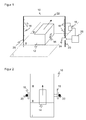
- FIG. 1 shows in a schematic three-dimensional representation and FIG. 2 in plan view, a first embodiment of a device according to the invention for reading information for the identification of an object 12, for example, a pallet, a package or any goods (logistic unit) carrying a transponder containing the information 14.
- a reading device 16 emits an electromagnetic field via antennas 18, which either stimulates the transponder 14 to actively radiate the stored information or which is changed in the transponder 14, this change or the returned information again be detected by the antennas 18.
- This type of readout of a transponder 14, also called RFID tag, via a corresponding reading device 16 or an RFID reader is known in principle and the invention requires no special implementation of RFID technology. In a preferred embodiment, however, the ultra-high frequency RFID technology is used with a backscatter transponder.
- the device 10 as a whole forms a reading gate, on whose lateral posts 20 the antennas 18 are mounted.
- the cross member 22 also shown connects the antennas 18 on both sides electrically.
- Such a cross brace 22 is not mandatory.
- the electrical connection between the antennas 18 and to the reading device 16 can also be done in other ways, for example by a simple laid on the ground line or wirelessly. Without this cross brace 22, the reading door 10 occupies significantly less space, therefore can not be damaged by passing objects and is easier to assemble or disassemble.
- an optoelectronic sensor 24 is mounted on a lateral post 20 .
- the sensor 24 monitors the passage area through the reading gate 10 in its viewing area. It is able to determine the position of the object 12.
- this sensor is a laser scanner whose scanning beam hits the object 12 at a known angle and can also detect at what distance this occurs. For this purpose, the light transit time from sensor 24 to object 12 and back is measured.
- the field of view of the sensor 24 is a plane which preferably lies horizontally and is divided into fields I-III. In a simplified embodiment, the sensor 24 then does not determine the exact position of the object 12, but only in which of the fields I-III the object 12 is currently located.
- the sensor 24 may, for example, also be a camera which, by means of an image evaluation, is likewise able to determine the position of the object 12 or the field I-III in which the object 12 lies.
- Both the reading device 16 and the sensor 24 are connected to a controller 26 of the reading gate 10.
- the controller 26 may be part of the sensor 24 or part of the RFID reader 16.
- the sensor 24 transmits the exact position of the object 12 or the currently occupied by the object 12 field I-III to the controller 26.
- the sensor 24 may be configured to geometrically measure the contour of the object 12 and this data also to the To transmit control 26.
- the RFID reader 16 can be addressed by the controller 26 to the Read transponder 14 and return the information thus determined to the controller 26.
- the readout method according to the invention in the device 10 then proceeds as follows.
- the object 12 moves in the direction indicated by the arrow through the reading gate 10.
- the object 12 may be arranged on a vehicle, not shown in the figures.
- This vehicle or means of transport can in turn have a transponder 14, which is read by an RFID reader and thus at any time allows to know the position of the means of transport and thus to track its route.
- this sensor 24 determines the position of the object 12 and reports position data to the controller 26 as long as the object 12 is in the field of vision.
- This position data can be three-dimensional coordinates in space, but also only the currently occupied by the object 12 field I-III.
- the sensor 24 may determine a contour of the object 12.
- the controller 26 compares the motion of the object 12 reported by the sensor 24 with a predetermined motion pattern.
- the controller 26 activates the reading device 16 in response to a specific movement pattern.
- the reading device 16 activates the transponder 14 for emitting the identification information stored there and returns this information to the controller 26.
- the movement pattern which results in the activation of the reading device 16 is a movement of the object 12 from a certain direction under the reading gate 10 in close proximity to the reading device 16.
- the controller 26 further compares the movement from the sensor 24 transmitted motion with the predetermined movement pattern. If these do not match, the information read out is discarded.
- the predetermined movement pattern is the further movement of the object 12 through the reading gate 10 to the other side and the subsequent exit from the reading gate 10.
- the information from the transponder 14 in a different movement of the object 12 from the expected movement either not read or at least not evaluated.
- the RFID reader 16 is only active when an object 12 to be identified by it is in the predetermined reading position. As a result, the time window is kept small, within which objects other than the object 12 at a greater distance, whose information should not be read at all, could lead to assignment errors.
- the controller 26 is also capable of evaluating geometric information about the object 12. This can be assessed via a finely resolved contour line of the object 12, but also over a comparatively coarse geometry information on the basis of the fields I-III swept by the object 12 at the same time. Thus, the controller 26 distinguishes between objects 12 to be read and spurious objects such as passing operators or empty pallets. If such an interfering object is detected, the reading device 16 remains deactivated or the information read out by it is discarded.
- the expected default motion is first the entry of object 12 into field I, which then leaves field I toward field II. Only on this sequence field I - field II towards the RFID reader 16 is activated and the transponder 14 is read out. If the object 12 leaves field I in a different direction than after field II, the reading device 16 remains deactivated. Only when the object 12 leaves field II to field III and then also leaves field III, the read information is assigned by the controller 26 to the object 12. If the object moves from field II to field I, the read information is discarded.
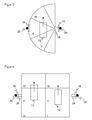
- FIG. 3 shows a second embodiment of the invention in plan view.
- like reference numerals designate the same features.
- This second embodiment differs from the first embodiment in that the monitoring plane is delimited by an arc describing a semicircle in the illustrated case.
- Fields I-III are also not rectangles, but circle segments.
- the reading method is the same as that used in connection with the first embodiment and the Figures 1 and 2 has been described.
- any further definition of fields is possible to define a given movement pattern. This depends on the application, the required simplicity of the evaluation and the accuracy of the motion to be prescribed, which should trigger a read operation.
- a laser scanner can detect and monitor any shape of the field, ie circle segments, rectangles or others, by using angles and distance measured polar coordinates are used, which completely cover the monitoring level.
- FIG. 4 shows in plan view a third embodiment of the invention, in which on both sides of the reading gate 10, an optoelectronic sensor 24, 25 is mounted.
- a second optoelectronic sensor 25 would not be necessary since the optoelectronic sensor 24 also knows the distance of the object 12 and thus could make a corresponding division alone.
- only with a second optoelectronic sensor 25 is it possible to track movements of a second object 13, which is in the shadow with respect to the first optoelectronic sensor 24 and can only be seen by the second optoelectronic sensor 25.
- two objects 12, 13 moved side by side by the reading gate 10 can also be identified by the same reading device 16 when the object 12, 13 is uniquely assigned to the information read out.
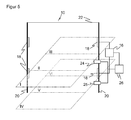
- a fourth embodiment which is in FIG. 5 is shown schematically in three dimensions, two optoelectronic sensors 24, 25 are arranged one above the other. In this way it is possible to obtain in the height dimension more accurate information about the object geometry and thus to better distinguish between objects to be read and not to be read.
- One application is the particularly reliable determination of the degree of loading of a pallet.
- the controller 26 can store previously read information from previous transponders 14 and compare it with a currently read information. If a transponder is then detected in the case of several passes, this can be recognized and sorted out by software, provided that it is not the transponder of a means of transport which is allowed to pass several times.
- this may be a logistic unit such as a pallet on which a larger number of objects are arranged, each carrying its own transponder.
- the reading device 16 is then able to read all these transponders and assign the thus identified objects to the palette.
- transponders In addition to the described transponders on goods and vehicles, there are also static transponders which are thus fixedly attached to a location, such as a machine, a shelf or the like. Such static transponders do not undergo any fields or trajectories and are therefore excluded from the evaluation according to the invention. It is simpler to provide suitable filters, which recognize the transponder as static, because it is read, for example, longer than a certain minimum time and thus exclude it from the outset as irrelevant. For this purpose, information about or from static transponders can be stored in said or another memory of the controller in order to be able to effectively filter them out.
- the invention it is possible to keep the individual RFID systems active only when they are really needed, and to read out only those objects which are brought into a predetermined reading position and, because of their movement pattern, actually should be read out.
- geometry properties ensure that basically only objects to be read, such as a loaded pallet or whatever is defined as a relevant object, are registered by the RFID system.
Landscapes
- Engineering & Computer Science (AREA)
- Physics & Mathematics (AREA)
- Toxicology (AREA)
- Health & Medical Sciences (AREA)
- Artificial Intelligence (AREA)
- Computer Vision & Pattern Recognition (AREA)
- General Physics & Mathematics (AREA)
- Theoretical Computer Science (AREA)
- Electromagnetism (AREA)
- General Health & Medical Sciences (AREA)
- Computer Networks & Wireless Communication (AREA)
- Radar Systems Or Details Thereof (AREA)
- Geophysics And Detection Of Objects (AREA)
- Optical Head (AREA)
Abstract
Description
Die Erfindung betrifft eine Vorrichtung und ein Verfahren zum Auslesen von Informationen mit einer Leseeinrichtung für Transponder nach dem Oberbegriff von Anspruch 1 beziehungsweise 11.The invention relates to a device and a method for reading out information with a reading device for transponders according to the preamble of claim 1 or 11.
Zur Automatisierung von logistischen Bewegungen ist die möglichst fehlerfreie Identifikation und Lageüberwachung von Objekten und Waren erforderlich. Dies geschieht an Identifikationspunkten, vor allem bei einem Wechsel des Besitzers der Ware oder einem Wechsel des Transportmittels. Ein automatisierendes Identifikationssystem wird demnach beispielsweise bei einem Wareneingang eines Logistikzentrums installiert, um eingehende und ausgehende Waren zu verzeichnen. Dies führt zu schnellen und nachvollziehbaren Logistikbewegungen.To automate logistical movements, the most error-free identification and situation monitoring of objects and goods is required. This is done at identification points, especially when changing the owner of the goods or a change of the means of transport. An automated identification system is therefore installed, for example, at a goods receipt of a logistics center to record incoming and outgoing goods. This leads to fast and traceable logistics movements.
Ein herkömmliches Verfahren zur automatisierten Identifikation ist, bei Durchfahrt einer Ladeeinheit wie etwa einer Palette, den Kennzeichnungsträger oder das Etikett an dieser Ladeeinheit oder dem von ihr geförderten Objekt mit Hilfe von stationären Barcodesystemen zu identifizieren. Die Lesegeräte, also Barcodescanner, werden über eine vorgelagerte Kombination von Lichtschranken ausgelöst.A conventional method of automated identification is, when passing through a loading unit, such as a pallet, to identify the tag or tag on that loading unit or the object being conveyed by means of stationary bar code systems. The readers, ie bar code scanners, are triggered by an upstream combination of light barriers.
Seit einiger Zeit wird versucht, die optische Abtastung per Barcodeleser durch RFID-Leser (Radio Frequency Identification) zu ersetzen. Dabei ist an dem zu identifizierenden Objekt anstelle eines Barcodes ein Transponder angebracht. Solche Transponder können prinzipiell aktiv sein, also eine eigene Energieversorgung aufweisen und selbstständig elektromagnetische Strahlung erzeugen. In der Praxis eignen sich diese Transponder für die Logistik aber weniger, weil durch die Energieversorgung die Stückpreise solcher Transponder nicht das für den Massenmarkt erforderliche geringe Niveau erreichen können. Deshalb werden zumeist passive Transponder ohne eigene Energieversorgung eingesetzt. In beiden Fällen wird durch elektromagnetische Strahlung des Lesegerätes der Transponder zur Abstrahlung der gespeicherten Information angeregt.For some time now, attempts have been made to replace the optical scanning by barcode reader with RFID (Radio Frequency Identification) readers. In this case, a transponder is attached to the object to be identified instead of a barcode. Such transponders can be active in principle, that is, have their own power supply and independently generate electromagnetic radiation. In practice, these transponders are less suitable for logistics, however, because the unit prices of such transponders can not reach the low level required for the mass market due to the energy supply. Therefore, mostly passive transponders without their own Energy supply used. In both cases, the transponder is excited to emit the stored information by electromagnetic radiation of the reading device.
Während es früher üblich war, eine Spule in den Transponder einzusetzen und ihn über induktive Kopplung auszulesen, werden inzwischen eher UHF-Transponder (Ultrahochfrequenz) eingesetzt, deren Antenne ein Dipol ist (Backscatter). Wenn hier und im Folgenden von Transponder und RFID-Leser die Rede ist, so soll dies aber unabhängig von der genauen Umsetzung der Technik verstanden werden.While it used to be customary to insert a coil into the transponder and read it out via inductive coupling, UHF transponders (ultra-high frequency) whose antenna is a dipole (backscatter) are now being used. If here and in the following of transponder and RFID reader is mentioned, but this should be understood regardless of the exact implementation of the technique.
Beim Einsatz von RFID-Lesern für die automatische Identifikation ergibt sich die Schwierigkeit, dass nicht unmittelbar klar ist, zu welchem Objekt eine ausgelesene Information eines Transponders gehört. Der Einsatz einer einfachen Lichtschranke vor dem RFID-Leser genügt nicht, weil die Lichtschranke weder die Bewegungsrichtung erkennen noch eine Entscheidung darüber treffen kann, ob ein Flurförderzeug mit voller oder leerer Ladeeinheit den Bereich durchfährt. Des Weiteren können auch Personen die Lichtschranken auslösen und damit zu Fehllesungen führen. Insoweit unterscheiden sich die Zuordnungsprobleme bei RFID-Lesern noch nicht von der herkömmlichen Lösung über Barcodescanner. Da aber RFID-Leser durch Reflexionen Transponder in Reichweiten erreichen können, welche über den Reichweiten ohne reflektierende Umgebung liegen, sogenannte "Überreichweiten", ist eine Zuordnung oft problematisch. Des Weiteren können sich die RFID-Leser bedingt durch die hohe Differenz von Sendeleistung und Empfangsempfindlichkeit gegenseitig bei der Auslesung der Transponder behindern. Das gilt insbesondere für Lagerhallen, in denen eine größere Anzahl von RFID-Lesern installiert ist.The use of RFID readers for automatic identification results in the difficulty that it is not immediately clear to which object a retrieved information of a transponder belongs. The use of a simple light barrier in front of the RFID reader is not sufficient because the light barrier can neither detect the direction of movement nor make a decision as to whether an industrial truck with a full or empty loading unit passes through the area. Furthermore, persons can trigger the light barriers and thus lead to incorrect readings. In that regard, the assignment problems with RFID readers do not yet differ from the conventional solution via bar code scanners. However, since RFID readers can reach transponders within ranges due to reflections, which lie over the ranges without reflecting environment, so-called "overreaching", an assignment is often problematic. Furthermore, due to the high difference between transmission power and reception sensitivity, the RFID readers can hinder each other when reading out the transponder. This is especially true for warehouses where a larger number of RFID readers are installed.
In einer herkömmlichen Lösung werden die Triggerlichtschranken durch eine Kombination aus einem Lichtgitter und einer Radarsensorik ersetzt. Das Lichtgitter kann die Höhe eines zu dem RFID-Leser geförderten Objekts bestimmen und damit grob das Objekt klassifizieren, beispielsweise ein leeres von einem beladenen Flurförderzeug unterscheiden. Der Radarsensor misst die Bewegungsrichtung über den Doppeleffekt. Der konstruktive Aufwand ist recht hoch, nicht nur weil ein Radarsensor benötigt wird, sondern weil dieser auch noch auf einer Querstange oberhalb der durchfahrenden Objekte montiert sein muss, um die Bewegungsrichtung messen zu können.In a conventional solution, the trigger light barriers are replaced by a combination of a light grid and a radar sensor. The light grid can determine the height of an object conveyed to the RFID reader and thus roughly classify the object, for example differentiate an empty from a loaded industrial truck. The radar sensor measures the direction of movement via the double effect. The design effort is quite high, not only because a radar sensor is needed, but because this must also be mounted on a crossbar above the passing objects in order to measure the direction of movement can.
Aus der
Schließlich ergibt sich eine weitere Schwierigkeit beim Einsatz einer großen Anzahl von RFID-Lesern in räumlicher Nähe zueinander daraus, dass nach der zu Grunde liegenden Norm EN 302 208 nur eine begrenzte Anzahl von Frequenzkanälen verfügbar ist, nämlich fünf Kanäle mit niedriger Leistung und 10 Kanäle mit einer Leistung von bis zu 2 W, was unter den gegebenen Werten für Sendeleistung und Grenzwert für die Kanalfreigabe einer Reichweite von bis zu 80 km entspricht. Sind mehr RFID-Leser gleichzeitig aktiv, muss jeweils nach einem freien Kanal gesucht werden und zudem treten durch die Überreichweite massive Zuordnungsprobleme auf. Durch die anvisierte Umstellung der Norm EN 302 208 würden sich die Regeln der Kanalfreigabe ändern, aber die Problematik bleibt dennoch grundsätzlich bestehen.Finally, a further difficulty in using a large number of RFID readers in close proximity to each other results from the fact that only a limited number of frequency channels are available, namely five low-power channels and ten channels, according to the underlying EN 302 208 standard a power of up to 2 W, which corresponds to a range of up to 80 km under the given values for transmission power and limit for the channel release. If more RFID readers are active at the same time, each must search for a free channel and also occur due to the overreach massive assignment problems. The envisaged conversion of the standard EN 302 208 would change the rules of channel approval, but the problem still exists.
Es ist daher Aufgabe der Erfindung, das Auslesen eines Transponders bei eindeutiger Zuordnung zu dem zugehörigen Objekt mit möglichst geringem Aufwand zu ermöglichen.It is therefore an object of the invention to enable the readout of a transponder when clearly assigned to the associated object with the least possible effort.
Diese Aufgabe wird durch eine Vorrichtung gemäß Anspruch 1 und ein Verfahren gemäß Anspruch 11 gelöst. Indem der optoelektronische Sensor ein Bewegungsmuster des Objekts bestimmen kann, lässt sich eindeutig feststellen, ob dieses Objekt die betreffende Leseeinrichtung passiert hat. Nur in diesem Fall werden die gelesenen Informationen auch ausgewertet. Dadurch lassen sich Fehllesungen drastisch reduzieren oder ganz vermeiden. Der Vorteil der erfindungsgemäßen Lösung liegt nicht nur in der somit stark verbesserten Leserate, sondern auch in einer schnelleren Auswertung und Übertragung der Informationen, weil nur noch relevante Daten ausgewertet werden müssen und viele Informationen bereits durch Messungen des optoelektronischen Sensors ausgefiltert werden. Die Erfindung eignet sich daher auch besonders für anspruchsvollere Logistikanwendungen, bei denen eine große Anzahl von RFID-Lesern eingesetzt wird.This object is achieved by a device according to claim 1 and a method according to claim 11. By the optoelectronic sensor can determine a movement pattern of the object, it can be clearly determined whether this object has passed the relevant reading device. Only in this case, the read information is also evaluated. As a result, incorrect readings can be drastically reduced or completely avoided. The advantage of the solution according to the invention lies not only in the thus greatly improved read rate, but also in a faster evaluation and transmission of the information, because only relevant data must be evaluated and many information is already filtered out by measurements of the optoelectronic sensor. The invention is therefore particularly suitable for more demanding Logistics applications where a large number of RFID readers are used.
Die Erfindung beruht dabei auf dem Prinzip, mögliche Fehllesungen direkt an der Quelle zu unterdrücken. Durch Einsatz eines leistungsfähigeren, aber immer noch kostengünstigen optoelektronischen Sensors, der die herkömmlichen Lichtschranken ersetzt, kann die anfällige und aufwändige Verarbeitung zahlreicher RFID-Informationen bereits im Vorfeld auf ein handhabbares Maß reduziert werden.The invention is based on the principle of suppressing possible incorrect readings directly at the source. By using a more powerful but still cost-effective opto-electronic sensor that replaces conventional photoelectric sensors, the delicate and complex processing of numerous RFID information can be reduced to a manageable level in advance.
Vorteilhafterweise ist die Steuerung dafür ausgebildet, die Leseeinrichtung nur dann zu aktivieren, wenn das Objekt das vorgegebene Bewegungsmuster wenigstens teilweise ausführt. Wie einleitend gesagt, ist die Zahl der zur Verfügung stehenden Kanäle begrenzt. Wenn jeder RFID-Leser nur einen kleinen Teil der Zeit aktiv ist, nämlich während er tatsächlich relevante Information zu lesen hat, wird diese knappe Ressource der zur Verfügung stehenden Kanäle zielgerichtet und effektiv ausgenutzt. Das beschleunigt die Lesevorgänge, weil nicht nach einem freien Kanal gesucht werden muss und schneidet die Möglichkeit von Fehllesungen aufgrund der Überreichweite der Leseeinrichtungen in einem signifikanten Maße ab. Die Anzahl der ohne Abstimmungsprobleme nebeneinander einsetzbaren RFID-Lesern kann damit wesentlich höher ausfallen.Advantageously, the controller is designed to activate the reading device only when the object at least partially executes the predetermined movement pattern. As we said in the introduction, the number of available channels is limited. If every RFID reader is only active for a small part of the time, namely while actually reading relevant information, this scarce resource of the available channels is used purposefully and effectively. This speeds up the reads because there is no need to search for a free channel and cuts off the possibility of miss readings due to the overreach of the readers to a significant degree. The number of RFID readers that can be used side by side without coordination problems can thus be much higher.
Bevorzugt weist das vorgegebene Bewegungsmuster eine Bewegungsrichtung auf. Über die Bewegungsrichtung lässt sich bereits eine große Anzahl von Bewegungsmustern erkennen, die eine Fehllesung auslösen könnten. Dazu zählt der Durchgang durch ein Lesetor in der falschen Richtung, aber auch eine Bewegungsumkehr vor, während oder nach dem eigentlichen Lesevorgang.The predetermined movement pattern preferably has a direction of movement. About the direction of movement can be seen already a large number of movement patterns that could trigger a misreading. This includes the passage through a reading gate in the wrong direction, but also a reversal of motion before, during or after the actual reading process.
In einer vorteilhaften Weiterbildung ist die Steuerung dafür ausgebildet, ausgelesene Informationen zu verwerfen, wenn das Objekt das vorgegebene Bewegungsmuster nicht vollständig ausführt. Die Entscheidung, ob ein Objekt überhaupt auszulesen ist, sollte dann fallen, wenn das Objekt sich in großer räumlicher Nähe der Leseeinrichtung befindet. Wenn aber danach das Bewegungsmuster nicht vervollständigt wird, würden diese ausgelesenen Informationen zu einer Fehllesung führen. Indem falsche Daten von vorneherein verworfen werden, ist diese Gefahr ausgeschlossen.In an advantageous development, the controller is designed to discard read information if the object does not completely execute the predetermined movement pattern. The decision as to whether an object should be read at all should then be made when the object is in close proximity to the reading device. But if thereafter the motion pattern is not completed, this read information would result in a misreading. By discarding false data from the outset, this danger is excluded.
Bevorzugt ist der optoelektronische Sensor und/oder die Steuerung für die Bestimmung einer Geometrieklasse ausgebildet, wobei insbesondere jeweils eine Person, eine beladene oder eine unbeladene Ladeeinheit wie eine Palette eine Geometrieklasse bildet. Neben dem Bewegungsmuster wird hiermit die Geometrieklasse als zweites Kriterium für die Entscheidung herangezogen, ob eine Lesung vorzunehmen ist. Im Normalfall soll weder eine unbeladene Palette noch eine Person eine Lesung auslösen. Weiterhin ist möglich, ein Lesetor speziell für bestimmte Objektklassen einzurichten, so dass es beispielsweise nur Pakete einer bestimmten Größe ausliest und alles andere passieren lässt, ohne dies zu registrieren. Erneut kann auf diese Weise die Fehlerrate reduziert werden.Preferably, the optoelectronic sensor and / or the controller for the determination of a geometry class is formed, in particular in each case a person, a loaded or an unloaded loading unit as a pallet a geometry class forms. In addition to the movement pattern, the geometry class is used as the second criterion for deciding whether a reading is to be made. Normally, neither an unloaded pallet nor a person should trigger a reading. Furthermore, it is possible to set up a reading gate specifically for certain object classes so that, for example, it only reads out packets of a certain size and lets everything else pass without registering. Again, the error rate can be reduced in this way.
Noch bevorzugter ist die Steuerung dafür ausgebildet, die Leseeinrichtung nur für Objekte einer vorgegebenen Geometrieklasse zu aktivieren und/oder nur die ausgelesene Information eines Objekts einer vorgegebenen Geometrieklasse auszuwerten. Auf diese Weise wird die Geometrieinformation mit unmittelbarem zeitlichen Bezug zu der Lesung ausgewertet und ein Objekt mit einer als irrelevant eingestuften Geometrie entweder gar nicht erst ausgelesen, indem die Leseeinrichtung deaktiviert bleibt, oder zumindest unmittelbar verworfen.More preferably, the controller is designed to activate the reading device only for objects of a predetermined geometry class and / or to evaluate only the read information of an object of a predetermined geometry class. In this way, the geometry information is evaluated with immediate temporal reference to the reading and an object with a classified as irrelevant geometry either not even read out by the reader remains disabled, or at least immediately discarded.
In einer bevorzugten Ausführungsform ist der optoelektronische Sensor ein Laserscanner, der insbesondere eine in Felder eingeteilte Überwachungsebene überwachen kann. Ein solcher Laserscanner ist in der Lage, die Position eines Objektes anhand der Entfernung und des Scanwinkels zu bestimmen, welches sich der Leseeinrichtung annähert. Damit kann das Bewegungsmuster wahlweise als fein aufgelöste Trajektorie, alternativ aber auch zur einfacheren Auswertung und Klassifizierung des Bewegungsmusters nur über eine Anzahl vordefinierter Felder bestimmt und/oder bewertet werden. Felder sind in der Arbeitsebene von Laserscannern in der geometrischen Form frei definierbare Bereiche. Diese Bereiche werden innerhalb ihrer Konturen auf Objekte überprüft. Sind innerhalb der gewählten Kontur Objekte vorhanden, können diese über entsprechende Interfaces angezeigt werden, wie Schaltausgänge oder Telegramme.In a preferred embodiment, the optoelectronic sensor is a laser scanner, which can in particular monitor a monitoring plane subdivided into fields. Such a laser scanner is able to determine the position of an object on the basis of the distance and the scan angle which approaches the reading device. Thus, the movement pattern can be determined and / or evaluated optionally as a finely resolved trajectory, but alternatively also for a simpler evaluation and classification of the movement pattern only over a number of predefined fields. Fields are freely definable areas in the working plane of laser scanners in the geometric form. These areas are checked for objects within their contours. If objects are present within the selected contour, they can be displayed via corresponding interfaces, such as switching outputs or telegrams.
Noch bevorzugter ist dabei das Bewegungsmuster über eine Reihenfolge der von dem Objekt nacheinander berührten Felder und/oder die Geometrieklasse anhand der gleichzeitig von dem Objekt überstrichenen Felder festgelegt. Für viele Anwendungen genügt es, lediglich in dieser Weise grobere Informationen über Bewegung und Geometrie aufzuzeichnen. Dies erleichtert die Zuordnung zu einer Bewegungsklasse oder einer Geometrieklasse und reduziert damit die Fehlerrate und den Auswertungsaufwand.More preferably, the movement pattern is determined by an order of the fields successively touched by the object and / or the geometry class on the basis of the fields swept simultaneously by the object. For many applications it is sufficient to record more rough information about motion and geometry only in this way. This facilitates the assignment to a motion class or a geometry class and thus reduces the error rate and the evaluation effort.
In einer besonderen Ausführungsform ist dabei das vorgegebene Bewegungsmuster durch das Eintreten in ein erstes Feld, den Übergang zunächst in ein zweites Feld und dann in ein drittes Feld und das Verlassen des dritten Feldes festgelegt, wobei insbesondere die Steuerung dafür ausgebildet ist, die Leseeinrichtung erst bei Übergang in das zweite Feld zu aktivieren und/oder die ausgelesene Information zu verwerfen, wenn nach Aktivierung der Leseeinrichtung das Objekt nicht zunächst in das dritte Feld übergeht und dieses anschließend verlässt. In dieser Ausführungsform genügt also die Überwachung von lediglich drei Feldern. Damit lässt sich bereits zuverlässig feststellen, ob ein Objekt tatsächlich in den Lesebereich eingetreten ist und ob es diesen auch in der richtigen Richtung wieder verlassen hat. Die Leseeinrichtung wird dann und nur dann aktiviert, wenn ein Objekt aus der richtigen Richtung in ihre Nähe kommt, und sofern das Objekt danach das Bewegungsmuster nicht vervollständigt und auf der gegenüberliegenden Seite aus dem Lesetor heraustritt, werden die ausgelesene Informationen verworfen, da sie irrelevant sind.In a particular embodiment, the predetermined movement pattern is by entering a first field, the transition first into a second field and then set in a third field and leaving the third field, in particular, the controller is designed to activate the reading device only at the transition to the second field and / or discard the read information, if after activation of the reading device, the object not initially goes into the third field and then leaves this. In this embodiment, therefore, the monitoring of only three fields is sufficient. This makes it possible to reliably determine whether an object has actually entered the reading area and whether it has left it in the right direction. The reading device is activated if and only if an object comes from the right direction in its vicinity, and if the object thereafter does not complete the movement pattern and on the opposite side emerges from the reading gate, the read information is discarded because they are irrelevant ,
Vorteilhafterweise ist die Steuerung dafür ausgebildet, den Fahrweg von Objekten tragenden Fahrzeugen mittels eines Transponders des Fahrzeugs zu ermitteln und aufzuzeichnen. Nicht nur die Objekte selbst, also in gewöhnlichen Logistikanwendungen die Waren, sondern auch die Transportmittel sind hier mit einem Transponder versehen. Für die zentrale Steuerung der Logistikhalle erleichtert es die Planung, wenn die Positionen der Transportmittel zu jedem Zeitpunkt bekannt sind.Advantageously, the controller is designed to determine the route of objects carrying vehicles by means of a transponder of the vehicle and record. Not only the objects themselves, ie the goods in ordinary logistics applications, but also the means of transport are here provided with a transponder. For the central control of the logistics hall it facilitates the planning, if the positions of the means of transport are known at any time.
In einer weiteren vorteilhaften Ausführungsform weist die Steuerung einen Speicher für ausgelesene Informationen auf und ist dafür ausgebildet, ausgelesene Informationen zu verwerfen, wenn sie identisch zu bereits früher ausgelesenen Informationen sind. In diesem Fall ist nämlich anzunehmen, dass der aktuelle gelesene Transponder aufgrund von Überreichweite gelesen wird und sich gar nicht in dem Lesetor befindet. Eine Ausnahme hierbei ist, wenn der Transponder sich an einem Transportmittel befindet, diese Transportmittel sind der Steuerung bekannt und werden von dieser vorteilhaften Weiterbildung ausgenommen.In a further advantageous embodiment, the controller has a memory for read information and is designed to discard read information if they are identical to previously read information. In this case, it can be assumed that the current read transponder is read due to overreach and is not in the reading gate at all. An exception here is when the transponder is located on a means of transport, these means of transport are known to the controller and are excluded from this advantageous development.
Bevorzugt sind mehrere optische Sensoren, insbesondere mehrere Laserscanner vorgesehen, und diese Sensoren weisen Felder in zumindest zwei nebeneinander liegenden Reihen zur Erkennung komplexerer Bewegungsmuster und/oder in zumindest zwei nebeneinander liegenden Ebenen zur Erkennung komplexerer Geometrieklassen auf. Damit lassen sich Lesetore realisieren, bei denen auch die Bewegungsmuster von nebeneinander das Lesetor passierenden Objekten überwacht werden können. Im Falle übereinander liegender Ebenen lässt sich beispielsweise nicht nur erkennen, ob eine Palette beladen ist, sondern auch wie hoch sie beladen ist.Preferably, a plurality of optical sensors, in particular a plurality of laser scanners are provided, and these sensors have fields in at least two adjacent rows for detecting more complex movement patterns and / or in at least two adjacent planes for the detection of complex geometry classes. This makes it possible to realize reading gates in which the movement patterns of objects passing next to one another can also be monitored. In the case of superimposed planes, for example, it is not only possible to detect whether a pallet is loaded, but also how high it is loaded.
In all diesen Fällen wurde immer nur ein Objekt angesprochen. Es ist erfindungsgemäß jedoch auch möglich, dass ein Transportmittel eine Vielzahl von Objekten fördert, die jeweils einen Transponder aufweisen. Diese Transponder können dann gleichzeitig oder nacheinander ausgelesen werden, während sie die Nähe der Leseeinrichtung passieren.In all these cases, only one object was ever addressed. However, it is also possible according to the invention that a transport means conveys a multiplicity of objects, each of which has a transponder. These transponders can then be read simultaneously or sequentially as they pass near the reader.
Das erfindungsgemäße Verfahren kann auf ähnliche Weise durch weitere Merkmale ausgestaltet werden und zeigt dabei ähnliche Vorteile. Derartige weitere Merkmale sind beispielhaft, aber nicht abschließend, in den sich an die unabhängigen Ansprüche anschließenden Unteransprüchen beschrieben.The inventive method can be configured in a similar manner by further features and shows similar advantages. Such further features are exemplary, but not exhaustive, in which subclaims following the independent claims are described.
Die Erfindung wird nachstehend auch hinsichtlich weiterer Vorteile und Merkmale unter Bezugnahme auf die beigefügte Zeichnung anhand von Ausführungsbeispielen erläutert. Die Figuren der Zeichnung zeigen in:
- Fig. 1
- eine schematische dreidimensionale Darstellung eines Lesetors in einer Ausführungsform der erfindungsgemäßen Vorrichtung mit einer Leseeinrichtung und einem optoelektronischen Sensor;
- Fig. 2
- eine Draufsicht auf das Lesetor gemäß
Figur 1 ; - Fig. 3
- eine Draufsicht auf eine zweite Ausführungsform der Erfindung mit einer durch einen Bogen begrenzten Überwachungsebene des optoelektronischen Sensors;
- Fig. 4
- eine Draufsicht auf eine dritte Ausführungsform der Erfindung mit zwei gegenüber angeordneten optoelektronischen Sensoren und deren doppelter Reihe von Überwachungsfeldern; und
- Fig.5
- eine schematische dreidimensionale Darstellung einer vierten Ausführungsform der Erfindung mit zwei übereinander angeordneten optoelektronischen Sensoren und deren übereinander angeordneten Überwachungsebenen.
- Fig. 1
- a schematic three-dimensional view of a reading gate in an embodiment of the device according to the invention with a reading device and an optoelectronic sensor;
- Fig. 2
- a plan view of the reading gate according to
FIG. 1 ; - Fig. 3
- a plan view of a second embodiment of the invention with a limited by a bow monitoring plane of the optoelectronic sensor;
- Fig. 4
- a plan view of a third embodiment of the invention with two opposing optoelectronic sensors and their double row of monitoring fields; and
- Figure 5
- a schematic three-dimensional representation of a fourth embodiment of the invention with two superimposed optoelectronic sensors and their superposed monitoring levels.
Die Vorrichtung 10 bildet als Ganzes ein Lesetor, an dessen seitlichen Pfosten 20 die Antennen 18 angebracht sind. Die ebenfalls dargestellte Querstrebe 22 verbindet die Antennen 18 zu beiden Seiten elektrisch. Eine solche Querstrebe 22 ist aber nicht zwingend erforderlich. Die elektrische Verbindung zwischen den Antennen 18 und zu der Leseeinrichtung 16 kann auch auf andere Weise erfolgen, beispielsweise durch eine einfache am Boden verlegte Leitung oder auch drahtlos. Ohne diese Querstrebe 22 nimmt das Lesetor 10 deutlich weniger Raum ein, kann daher von durchfahrenden Objekten nicht beschädigt werden und ist leichter zu montieren oder zu demontieren.The
An einem seitlichen Pfosten 20 ist ein optoelektronischer Sensor 24 angebracht. Der Sensor 24 überwacht in seinem Sichtbereich den Durchgangsbereich durch das Lesetor 10. Er ist in der Lage, die Position des Objekts 12 zu ermitteln. In der dargestellten Ausführungsform ist dieser Sensor ein Laserscanner, dessen Abtaststrahl bei bekanntem Winkel auf das Objekt 12 trifft und auch erkennen kann, in welcher Entfernung dies geschieht. Dazu wird die Lichtlaufzeit von Sensor 24 zu Objekt 12 und zurück gemessen. Der Sichtbereich des Sensors 24 ist eine Ebene, die bevorzugt waagerecht liegt und in Felder I-III eingeteilt wird. In einer vereinfachten Ausführungsform bestimmt dann der Sensor 24 nicht die exakte Lage des Objekts 12, sondern nur, in welchem der Felder I-III das Objekt 12 aktuell liegt. Als Alternative zu einem Laserscanner kann der Sensor 24 beispielsweise auch eine Kamera sein, welche mittels einer Bildauswertung ebenfalls in der Lage ist, die Position des Objekts 12 oder das Feld I-III zu bestimmen, in dem das Objekt 12 liegt.On a
Sowohl die Leseeinrichtung 16 wie der Sensor 24 sind an eine Steuerung 26 des Lesetors 10 angeschlossen. Alternativ kann die Steuerung 26 Teil des Sensors 24 oder Teil des RFID-Lesers 16 sein. Der Sensor 24 übermittelt die genau Position des Objekts 12 oder das aktuell von dem Objekt 12 besetzte Feld I-III an die Steuerung 26. Zusätzlich kann der Sensor 24 dafür ausgebildet sein, die Kontur des Objekts 12 geometrisch zu vermessen und diese Daten ebenfalls an die Steuerung 26 zu übermitteln. Der RFID-Leser 16 kann von der Steuerung 26 angesprochen werden, um den Transponder 14 auszulesen und die so ermittelten Informationen an die Steuerung 26 zurückzugeben.Both the
Das erfindungsgemäße Ausleseverfahren in der Vorrichtung 10 läuft dann wie folgt ab. Das Objekt 12 bewegt sich in der durch den Pfeil angedeuteten Richtung durch das Lesetor 10. Dazu kann das Objekt 12 auf einem in den Figuren nicht dargestellten Fahrzeug angeordnet sein. Dieses Fahrzeug oder Transportmittel kann seinerseits einen Transponder 14 aufweisen, der von einem RFID-Leser ausgelesen wird und damit zu jeder Zeit ermöglicht, die Position des Transportmittels zu kennen und damit dessen Fahrweg nachzuverfolgen. Sobald das Objekt 12 in Sichtweite des Sensors 24 gelangt, stellt dieser Sensor 24 die Position des Objekts 12 fest und meldet Positionsdaten so lange an die Steuerung 26, wie das Objekt 12 sich im Sichtbereich aufhält. Diese Positionsdaten können dreidimensionale Koordinaten im Raum sein, aber auch lediglich das aktuell von dem Objekt 12 belegte Feld I-III. Zusätzlich kann der Sensor 24 eine Kontur des Objekts 12 bestimmen.The readout method according to the invention in the
Die Steuerung 26 vergleicht die von dem Sensor 24 gemeldete Bewegung des Objekts 12 mit einem vorgegebene Bewegungsmuster. Auf ein bestimmtes Bewegungsmuster hin aktiviert die Steuerung 26 die Leseeinrichtung 16. Die Leseeinrichtung 16 regt den Transponder 14 zur Abstrahlung der dort gespeicherten Identifikationsinformationen an und gibt diese Informationen an die Steuerung 26 zurück. In einer bevorzugten Ausführungsform ist das Bewegungsmuster, welches zur Aktivierung der Leseeinrichtung 16 führt, eine Bewegung des Objekts 12 aus einer bestimmten Richtung unter das Lesetor 10 in unmittelbarer Nähe zu der Leseeinrichtung 16. Nach dem Auslesen durch die Leseeinrichtung 16 vergleicht die Steuerung 26 weiterhin die von dem Sensor 24 übermittelte Bewegung mit dem vorgegebene Bewegungsmuster. Stimmen diese nicht überein, so wird die ausgelesene Information verworfen. Bei der soeben angesprochenen bevorzugten Ausführungsform ist das vorgegebenen Bewegungsmuster die Weiterbewegung des Objekts 12 durch das Lesetor 10 hindurch auf die andere Seite und das anschließende Verlassen des Lesetors 10.The
Somit werden die Informationen aus dem Transponder 14 bei einer abweichenden Bewegung des Objekts 12 von der erwarteten Bewegung entweder gar nicht erst ausgelesen oder zumindest nicht ausgewertet. Der RFID-Leser 16 ist nur aktiv, wenn ein von ihm zu identifizierendes Objekt 12 in der vorgegebenen Leseposition ist. Dadurch wird das Zeitfenster klein gehalten, innerhalb dessen andere Objekte als das Objekt 12 in größerer Entfernung, deren Information gar nicht gelesen werden soll, zu Zuordnungsfehlern führen könnten.Thus, the information from the
Zusätzlich zu dem Vergleich mit einem vorgegebenen Bewegungsmuster ist die Steuerung 26 auch in der Lage, geometrische Informationen über das Objekt 12 auszuwerten. Dies kann über eine fein aufgelöste Konturlinie des Objekts 12, aber auch über eine vergleichsweise grobe Geometrieinformation anhand der gleichzeitig von dem Objekt 12 überstrichenen Felder I-III beurteilt werden. Damit unterscheidet die Steuerung 26 zwischen Objekten 12, die gelesen werden sollen und Störobjekten, wie vorbeigehendem Bedienpersonal oder leeren Paletten. Wird ein solches Störobjekt erkannt, so bleibt die Leseeinrichtung 16 deaktiviert oder die von ihr ausgelesenen Informationen werden verworfen.In addition to the comparison with a given movement pattern, the
Bei einer typischen beispielhaften Anwendung, die auf den Feldern I-III eines Laserscanners 24 basiert, ist die erwartete vorgegebene Bewegung zunächst der Eintritt des Objekts 12 in das Feld I, das anschließend das Feld I in Richtung Feld II verlässt. Nur auf diese Sequenz Feld I - Feld II hin wird der RFID-Leser 16 aktiviert und der Transponder 14 ausgelesen. Verlässt das Objekt 12 Feld I in eine andere Richtung als nach Feld II, so bleibt die Leseeinrichtung 16 deaktiviert. Nur wenn das Objekt 12 Feld II nach Feld III verlässt und anschließend auch Feld III verlässt, wird die ausgelesene Information von der Steuerung 26 dem Objekt 12 zugeordnet. Bewegt sich das Objekt von Feld II nach Feld I, so wird die ausgelesene Information verworfen. Bei einer Bewegung von Feld III nach Feld II geschieht zunächst nichts, da abzuwarten bleibt, ob Feld II in Richtung Feld I verlassen wird - in diesem Fall wird die gelesene Information verworfen - oder ob das Bewegungsmuster in einem weiteren Anlauf doch noch vollendet wird und die Zuordnung vorgenommen werden kann.In a typical example application based on fields I-III of a
In einer vierten Ausführungsform, die in
Aufgrund des überwachten Bewegungsmusters und der Objektgeometrie treten Zuordnungsfehler zwischen ausgelesener Informationen aus dem Transponder 14 und dem zugehörigen Objekt 12 nur noch wesentlich seltener auf. Dennoch ist nicht auszuschließen, dass in dem Moment, in dem die Leseeinrichtung 16 wegen eines erkannten Bewegungsmusters aktiviert ist, sich auch noch ein weiterer Transponder in Lesereichweite befindet. Um den hieraus entstehenden Fehlern zu begegnen, kann die Steuerung 26 bisher gelesene Informationen aus früheren Transpondern 14 speichern und mit einer aktuell ausgelesenen Information vergleichen. Wird dann ein Transponder bei mehreren Durchfahrten erfasst, so kann dies softwaremäßig erkannt und aussortiert werden, sofern es sich nicht um den Transponder eines Transportmittels handelt, welchem mehrere Durchfahrten erlaubt sind.Due to the monitored movement pattern and the object geometry, assignment errors between read-out information from the
Obwohl in den Figuren jeweils nur ein Objekt 14 dargestellt ist, kann es sich hierbei um eine logistische Einheit wie eine Palette handeln, auf der eine größere Anzahl von Objekten angeordnet sind, die jeweils eigene Transponder tragen. Die Leseeinrichtung 16 ist dann in einer Lage, alle diese Transponder auszulesen und die somit identifizierten Objekte der Palette zuzuordnen.Although only one
Es gibt über die beschriebenen Transponder an Waren und Fahrzeugen hinaus auch noch statische Transponder, die also fix an einem Ort angebracht sind, wie etwa einer Maschine, einem Regal oder dergleichen. Solche statischen Transponder durchlaufen keine Felder oder Trajektorien und werden daher erfindungsgemäß von der Auswertung ausgeschlossen. Einfacher ist es, geeignete Filter vorzusehen, welche den Transponder als statisch erkennen, weil er beispielsweise länger als eine gewisse Mindestzeit gelesen wird und ihn somit von vorneherein als nicht relevant auszuschließen. Dazu können Informationen über oder von statischen Transpondern in dem genannten oder einem weiteren Speicher der Steuerung abgelegt werden, um sie effektiv ausfiltern zu können.In addition to the described transponders on goods and vehicles, there are also static transponders which are thus fixedly attached to a location, such as a machine, a shelf or the like. Such static transponders do not undergo any fields or trajectories and are therefore excluded from the evaluation according to the invention. It is simpler to provide suitable filters, which recognize the transponder as static, because it is read, for example, longer than a certain minimum time and thus exclude it from the outset as irrelevant. For this purpose, information about or from static transponders can be stored in said or another memory of the controller in order to be able to effectively filter them out.
Insgesamt gelingt es erfindungsgemäß, die einzelnen RFID-Systeme nur dann aktiv zu halten, wenn sie wirklich benötigt werden, und nur solche Objekte auszulesen, die in eine vorgegebene Leseposition gebracht werden und aufgrund ihres Bewegungsmusters auch tatsächlich ausgelesen werden sollen. Zusätzlich wird über Geometrieeigenschaften sichergestellt, dass grundsätzlich nur auszulesende Objekte, wie etwa eine beladene Palette oder was immer als relevantes Objekt definiert ist, vom RFID-System registriert werden. Dadurch wird gerade in komplexeren Anwendungen mit einer größeren Anzahl von RFID-Lesern der Auswertungsaufwand ganz erheblich reduziert und gleichzeitig die Leserate erhöht, also die Identifizierung des jeweils richtigen Objektes.On the whole, according to the invention, it is possible to keep the individual RFID systems active only when they are really needed, and to read out only those objects which are brought into a predetermined reading position and, because of their movement pattern, actually should be read out. In addition, geometry properties ensure that basically only objects to be read, such as a loaded pallet or whatever is defined as a relevant object, are registered by the RFID system. As a result, especially in more complex applications with a larger number of RFID readers, the evaluation effort is considerably reduced and at the same time the read rate is increased, ie the identification of the respectively correct object.
Claims (15)
dass der optoelektronische Sensor (24) ein Bewegungsmuster des Objekts (12) bestimmen kann
und dass die Steuerung (26) dafür ausgebildet ist, die ausgelesenen Informationen nur bei Objekten (12) eines vorgegebenen Bewegungsmusters auszuwerten.Device (10) for reading out information from a transponder (14) arranged on an object (12), which device has an optoelectronic sensor (24), a reading device (16) which excites the transponder (14) for emitting the information and which is radiated Information can read, and a controller (26), which is designed for driving the reading device (16) and the sensor (24) and an evaluation of the read information, characterized in that
in that the optoelectronic sensor (24) can determine a movement pattern of the object (12)
and that the controller (26) is adapted to evaluate the information read only in objects (12) of a predetermined movement pattern.
wobei die Steuerung (26) dafür ausgebildet ist, die Leseeinrichtung (16) nur dann zu aktivieren, wenn das Objekt (12) das vorgegebene Bewegungsmuster wenigstens teilweise ausführt und/oder wobei die Steuerung (26) einen Speicher für ausgelesene Informationen aufweist und dafür ausgebildet ist, ausgelesene Informationen zu verwerfen, wenn sie identisch zu bereits früher ausgelesenen Informationen sind.Device (10) according to claim 1,
wherein the controller (26) is adapted to activate the reading device (16) only when the object (12) at least partially executes the predetermined movement pattern and / or wherein the controller (26) comprises and stores memory for read information is to discard read information if they are identical to previously read information.
wobei das vorgegebene Bewegungsmuster eine Bewegungsrichtung aufweist.Device (10) according to claim 1 or 2,
wherein the predetermined movement pattern has a direction of movement.
wobei die Steuerung (26) dafür ausgebildet ist, ausgelesene Informationen zu verwerfen, wenn das Objekt (12) das vorgegebene Bewegungsmuster nicht vollständig ausführt.Device (10) according to one of the preceding claims,
wherein the controller (26) is adapted to discard read information if the object (12) does not completely execute the predetermined movement pattern.
wobei der optoelektronische Sensor (24) und/oder die Steuerung (26) für die Bestimmung einer Geometrieklasse ausgebildet ist, und wobei insbesondere jeweils eine Person, eine beladene oder eine unbeladene Ladeeinheit wie eine
Palette eine Geometrieklasse bildet.Device (10) according to one of the preceding claims,
wherein the optoelectronic sensor (24) and / or the controller (26) is designed for the determination of a geometry class, and wherein in particular in each case a person, a loaded or an unloaded loading unit such as
Palette forms a geometry class.
wobei die Steuerung (26) dafür ausgebildet ist, die Leseeinrichtung nur für Objekte (12) einer vorgegebenen Geometrieklasse zu aktivieren und/oder nur die ausgelesenen Informationen eines Objekts (12) einer vorgegebenen Geometrieklasse auszuwerten.Device (10) according to claim 5,
wherein the controller (26) is adapted to activate the reading device only for objects (12) of a predetermined geometry class and / or to evaluate only the read-out information of an object (12) of a predetermined geometry class.
wobei der optoelektronische Sensor (24) ein Laserscanner ist, der insbesondere eine in Felder (I-VI) eingeteilte Überwachungsebene überwachen kann, wobei das Bewegungsmuster über eine Reihenfolge der von dem Objekt (12) nacheinander berührten Felder (I-VI) und/oder die Geometrieklasse anhand der gleichzeitig von dem Objekt (12) überstrichenen Felder (I-VI) festgelegt ist.Device (10) according to one of the preceding claims,
wherein the optoelectronic sensor (24) is a laser scanner, which can in particular monitor a monitoring plane subdivided into fields (I-VI), wherein the movement pattern is determined by an order of the fields (I-VI) and / or successively touched by the object (12) the geometry class is determined based on the fields (I-VI) swept simultaneously by the object (12).
wobei das vorgegebene Bewegungsmuster durch das Eintreten in ein erstes Feld (I), den Übergang zunächst in ein zweites Feld (II) und dann in ein drittes Feld (III) und das Verlassen des dritten Feldes (III) festgelegt ist, wobei insbesondere die Steuerung (26) dafür ausgebildet ist, die Leseeinrichtung (16) erst bei Übergang in das zweite Feld (II) zu aktivieren und/oder die ausgelesene Information zu verwerfen, wenn nach Aktivierung der Leseeinrichtung (16) das Objekt (12) nicht zunächst in das dritte Feld (III) übergeht und dieses anschließend verlässt.Device (10) according to claim 7,
wherein the predetermined movement pattern is defined by the entry into a first field (I), the transition first to a second field (II) and then to a third field (III) and leaving the third field (III), in particular the controller (26) is designed to activate the reading device (16) only when it enters the second field (II) and / or to discard the read information if after activation of the reading device (16) the object (12) does not first enter the third field (III) passes and then leaves.
wobei die Steuerung (26) dafür ausgebildet ist, den Fahrweg von Objekten (12) tragenden Fahrzeugen mittels eines Transponders (14) des Fahrzeugs zu ermitteln und aufzuzeichnen.Device (10) according to one of the preceding claims,
wherein the controller (26) is adapted to detect and record the travel path of vehicles carrying objects (12) by means of a transponder (14) of the vehicle.
wobei mehrere optische Sensoren (24, 25), insbesondere mehrere Laserscanner vorgesehen sind, und diese Sensoren Felder (I-VI) in zumindest zwei nebeneinanderliegenden Reihen (I-III; IV-VI) zur Erkennung komplexerer Bewegungsmuster und/oder in zumindest zwei übereinanderliegenden Ebenen (I-III; IV-VI) zur Erkennung komplexerer Geometrieklassen aufweisen.Device (10) according to one of the preceding claims,
wherein a plurality of optical sensors (24, 25), in particular a plurality of laser scanners are provided, and these sensors fields (I-VI) in at least two adjacent rows (I-III; IV-VI) for detecting more complex movement patterns and / or in at least two superimposed Layers (I-III, IV-VI) to recognize more complex geometry classes.
dass mittels eines optoelektronischen Sensors (24), insbesondere eines Laserscanners, ein Bewegungsmuster des Objekts (12) bestimmt wird und die ausgelesenen Informationen nur bei Objekten (12) eines vorgegebenen Bewegungsmusters, insbesondere einer vorgegebenen Bewegungsrichtung ausgewertet werden.Method for reading out information from a transponder (14) arranged on an object (12) by means of a reading device (16) which excites the transponder (14) to radiate the information and reads the radiated information, characterized
in that a movement pattern of the object (12) is determined by means of an optoelectronic sensor (24), in particular a laser scanner, and the read-out information is evaluated only for objects (12) of a predetermined movement pattern, in particular a predetermined direction of movement.
wobei die Leseeinrichtung (16) nur dann aktiviert wird, wenn das Objekt (12) das vorgegebene Bewegungsmuster wenigstens teilweise ausführt und/oder ausgelesene Informationen verworfen werden, wenn das Objekt (12) das vorgegebene Bewegungsmuster nicht vollständig ausführt und/oder wobei die ausgelesenen Informationen verworfen werden, wenn sie identisch zu gespeicherten bereits früher ausgelesenen Informationen sind.Method according to claim 11,
wherein the reading device (16) is activated only when the object (12) at least partially executes the predetermined movement pattern and / or discarded information is discarded when the object (12) does not completely execute the predetermined movement pattern and / or wherein the read-out information be discarded if they are identical to stored previously read information.
wobei eine Geometrieklasse bestimmt wird, und wobei insbesondere jeweils eine Person, eine beladene oder eine unbeladene Ladeeinheit wie eine Palette eine Geometrieklasse bildet, und wobei die Leseeinrichtung nur für Objekte (12) einer vorgegebenen Geometrieklasse aktiviert wird und/oder nur die ausgelesene Information eines Objekts (12) einer vorgegebenen Geometrieklasse ausgewertet wird.Method according to claim 11 or 12,
wherein a geometry class is determined, and wherein in particular in each case a person, a loaded or an unloaded loading unit such as a pallet forms a geometry class, and wherein the reading device is activated only for objects (12) of a predetermined geometry class and / or only the read information of an object (12) of a given geometry class is evaluated.
wobei der Sichtbereich des optoelektronischen Sensors in Felder eingeteilt wird und wobei das Bewegungsmuster über eine Reihenfolge der von dem Objekt nacheinander berührten Felder und/oder die Geometrieklasse anhand der gleichzeitig von dem Objekt überstrichenen Felder festgelegt wird, wobei insbesondere unter Einsatz einer Mehrzahl optoelektronischer Sensoren Felder in zumindest zwei nebeneinanderliegenden Reihen zur Erkennung komplexerer Bewegungsmuster und/oder in zumindest zwei Ebenen zur Erkennung komplexerer Geometrieklassen vorgesehen sind.Method according to one of claims 11 to 13,
wherein the field of view of the optoelectronic sensor is divided into fields and wherein the movement pattern is determined by an order of the fields successively touched by the object and / or the geometry class on the basis of simultaneously swept by the object fields, in particular using a plurality of optoelectronic sensors fields in at least two adjacent rows are provided for the detection of more complex movement patterns and / or in at least two levels for the detection of complex geometry classes.
wobei das vorgegebene Bewegungsmuster durch das Eintreten in ein erstes Feld, den Übergang zunächst in ein zweites Feld und dann in ein drittes Feld und das Verlassen des dritten Feldes festgelegt wird, wobei insbesondere die Leseeinrichtung erst bei Übergang in das zweite Feld aktiviert wird und/oder die ausgelesene Information verworfen wird, wenn nach Aktivierung der Leseeinrichtung das Objekt nicht zunächst in das dritte Feld übergeht und dieses anschließend verlässt.Method according to claim 14,
wherein the predetermined movement pattern is determined by entering a first field, the transition first into a second field and then into a third field and leaving the third field, wherein in particular the reading device is activated only at the transition to the second field and / or the read-out information is discarded if, after activation of the reading device, the object does not first pass into the third field and then leaves the latter.
Applications Claiming Priority (1)
| Application Number | Priority Date | Filing Date | Title |
|---|---|---|---|
| DE102007030738A DE102007030738A1 (en) | 2007-07-02 | 2007-07-02 | Reading information with optoelectronic sensor and RFID reader |
Publications (2)
| Publication Number | Publication Date |
|---|---|
| EP2012253A1 true EP2012253A1 (en) | 2009-01-07 |
| EP2012253B1 EP2012253B1 (en) | 2009-08-19 |
Family
ID=39776435
Family Applications (1)
| Application Number | Title | Priority Date | Filing Date |
|---|---|---|---|
| EP08104280A Active EP2012253B1 (en) | 2007-07-02 | 2008-06-06 | Reading of information with optoelectronic sensor and RFID reader |
Country Status (5)
| Country | Link |
|---|---|
| US (1) | US8026815B2 (en) |
| EP (1) | EP2012253B1 (en) |
| AT (1) | ATE440338T1 (en) |
| DE (2) | DE102007030738A1 (en) |
| ES (1) | ES2330901T3 (en) |
Cited By (3)
| Publication number | Priority date | Publication date | Assignee | Title |
|---|---|---|---|---|
| WO2013040256A2 (en) | 2011-09-13 | 2013-03-21 | Eagile, Inc. | Portal with rfid tag reader and object recognition functionality |
| DE102016208520A1 (en) | 2016-05-18 | 2017-11-23 | Fraunhofer-Gesellschaft zur Förderung der angewandten Forschung e.V. | Reading device for RFID |
| EP3425256A1 (en) * | 2017-06-06 | 2019-01-09 | Sick AG | Access protection system |
Families Citing this family (9)
| Publication number | Priority date | Publication date | Assignee | Title |
|---|---|---|---|---|
| JP5243868B2 (en) * | 2008-07-09 | 2013-07-24 | インターナショナル・ビジネス・マシーンズ・コーポレーション | Apparatus and method for recognizing information held by IC tag |
| DE102010020531A1 (en) | 2010-05-14 | 2011-11-17 | Sick Ag | Radio frequency identification reader for identifying e.g. goods in parcel sender, of airport, has evaluation unit detecting whether transponder moves on conveyor or by reading portal based on receiving intensity of signals and angles |
| DE102010022967A1 (en) * | 2010-06-08 | 2011-12-08 | Johannes Giesser Messerfabrik Gmbh | System and method for monitoring tools |
| DE102011110132B4 (en) * | 2011-08-15 | 2017-07-06 | Fraunhofer-Gesellschaft zur Förderung der angewandten Forschung e.V. | Method for automatic identification of missing or unread goods of a charging unit |
| US20150042795A1 (en) * | 2012-02-29 | 2015-02-12 | Reshimo Ltd. | Tracking system for objects |
| ES2443081B1 (en) * | 2012-08-17 | 2015-01-29 | Universidade Da Coruña | Automatic vehicle identification by RFID with Inductive Loop Detector |
| EP2927838B1 (en) | 2014-04-02 | 2016-03-16 | Sick Ag | System and method for identifying and locating objects |
| ES2597746B1 (en) * | 2015-07-20 | 2018-01-09 | Ipf Ingenieria Del Poliuretano Flexible, S.L. | SYSTEM AND PROCEDURE FOR CONTROL AND MANAGEMENT OF POLYURETHANE FOAM BLOCKS |
| EP3470879B1 (en) | 2017-10-16 | 2020-12-02 | Sick Ag | Optoelectronic sensor and method for securely detecting objects |
Citations (5)
| Publication number | Priority date | Publication date | Assignee | Title |
|---|---|---|---|---|
| DE19940403A1 (en) | 1999-08-25 | 2001-03-01 | Sick Ag | Method and device for identifying and determining the position of objects |
| US20020104013A1 (en) | 2001-02-01 | 2002-08-01 | Ohanes Ghazarian | Electronic vehicle product and personal monitoring |
| DE102004012220A1 (en) * | 2004-03-12 | 2005-09-29 | Sick Ag | Optoelectronic sensor for detecting objects conveyed along a conveyor device has a transmitter and a receiver with separate channels to cover a monitoring area |
| EP1684209A2 (en) | 2005-01-20 | 2006-07-26 | Kabushiki Kaisha Toshiba | Radio communication apparatus and radio communication method |
| US20060290472A1 (en) * | 2004-10-29 | 2006-12-28 | Kimberly Clark Worldwide, Inc. | Adjusting data tag readers with feed-forward data |
Family Cites Families (6)
| Publication number | Priority date | Publication date | Assignee | Title |
|---|---|---|---|---|
| US5708423A (en) * | 1995-05-09 | 1998-01-13 | Sensormatic Electronics Corporation | Zone-Based asset tracking and control system |
| US20020014533A1 (en) * | 1995-12-18 | 2002-02-07 | Xiaxun Zhu | Automated object dimensioning system employing contour tracing, vertice detection, and forner point detection and reduction methods on 2-d range data maps |
| US5682032A (en) * | 1996-02-22 | 1997-10-28 | Philipp; Harald | Capacitively coupled identity verification and escort memory apparatus |
| US5662032A (en) * | 1996-03-15 | 1997-09-02 | Baratta; Joseph P. | Juicer attachment for a blender |
| DE10106400B4 (en) * | 2001-02-12 | 2004-07-15 | Siemens Ag | Access control system |
| DE50308685D1 (en) * | 2003-05-22 | 2008-01-10 | Delphi Tech Inc | Method and device for activating an electronic circuit in a motor vehicle |
-
2007
- 2007-07-02 DE DE102007030738A patent/DE102007030738A1/en not_active Withdrawn
-
2008
- 2008-06-06 AT AT08104280T patent/ATE440338T1/en active
- 2008-06-06 EP EP08104280A patent/EP2012253B1/en active Active
- 2008-06-06 DE DE502008000085T patent/DE502008000085D1/en active Active
- 2008-06-06 ES ES08104280T patent/ES2330901T3/en active Active
- 2008-07-01 US US12/216,193 patent/US8026815B2/en active Active
Patent Citations (5)
| Publication number | Priority date | Publication date | Assignee | Title |
|---|---|---|---|---|
| DE19940403A1 (en) | 1999-08-25 | 2001-03-01 | Sick Ag | Method and device for identifying and determining the position of objects |
| US20020104013A1 (en) | 2001-02-01 | 2002-08-01 | Ohanes Ghazarian | Electronic vehicle product and personal monitoring |
| DE102004012220A1 (en) * | 2004-03-12 | 2005-09-29 | Sick Ag | Optoelectronic sensor for detecting objects conveyed along a conveyor device has a transmitter and a receiver with separate channels to cover a monitoring area |
| US20060290472A1 (en) * | 2004-10-29 | 2006-12-28 | Kimberly Clark Worldwide, Inc. | Adjusting data tag readers with feed-forward data |
| EP1684209A2 (en) | 2005-01-20 | 2006-07-26 | Kabushiki Kaisha Toshiba | Radio communication apparatus and radio communication method |
Cited By (7)
| Publication number | Priority date | Publication date | Assignee | Title |
|---|---|---|---|---|
| WO2013040256A2 (en) | 2011-09-13 | 2013-03-21 | Eagile, Inc. | Portal with rfid tag reader and object recognition functionality |
| EP2756460A4 (en) * | 2011-09-13 | 2015-05-06 | Eagile Inc | PORTAL HAVING AN RFID TAG READER AND OBJECT RECOGNITION FUNCTIONALITY |
| US10096218B2 (en) | 2011-09-13 | 2018-10-09 | Eagile, Inc. | Portal with RFID tag reader and object recognition functionality, and method of utilizing same |
| DE102016208520A1 (en) | 2016-05-18 | 2017-11-23 | Fraunhofer-Gesellschaft zur Förderung der angewandten Forschung e.V. | Reading device for RFID |
| DE102016208520B4 (en) | 2016-05-18 | 2019-02-14 | Fraunhofer-Gesellschaft zur Förderung der angewandten Forschung e.V. | Reading device for RFID |
| EP3425256A1 (en) * | 2017-06-06 | 2019-01-09 | Sick AG | Access protection system |
| US10495256B2 (en) | 2017-06-06 | 2019-12-03 | Sick Ag | Access control system |
Also Published As
| Publication number | Publication date |
|---|---|
| DE502008000085D1 (en) | 2009-10-01 |
| EP2012253B1 (en) | 2009-08-19 |
| ES2330901T3 (en) | 2009-12-16 |
| US20090015380A1 (en) | 2009-01-15 |
| ATE440338T1 (en) | 2009-09-15 |
| US8026815B2 (en) | 2011-09-27 |
| DE102007030738A1 (en) | 2009-01-08 |
Similar Documents
| Publication | Publication Date | Title |
|---|---|---|
| EP2012253B1 (en) | Reading of information with optoelectronic sensor and RFID reader | |
| EP1079322B1 (en) | Method and apparatus for identification and position determination of objects | |
| DE10107208B4 (en) | System for communicating with high-frequency labels | |
| EP2439487A1 (en) | Volume measuring device for mobile objects | |
| EP3291144B1 (en) | Rfid device and method for detecting compartment occupation | |
| EP2927838B1 (en) | System and method for identifying and locating objects | |
| EP2385014B1 (en) | Industrial truck with a device for identifying a loaded transport good and method for identifying a loaded transport good | |
| EP2881762A2 (en) | Optoelectronic sensor and method for detecting glossy objects | |
| EP2500850B1 (en) | Method and system for monitoring objects | |
| EP3279686B1 (en) | Radio frequency identification device for communicating with rfid transponders and method for allocating rfid transponders | |
| EP2108879B1 (en) | Method and device for security monitoring of a passage | |
| EP3825731B1 (en) | Optoelectronic safety sensor and method for guaranteed determination of own position | |
| EP3273382B1 (en) | Rfid reading device and method for compartment occupancy detection in a shelf | |
| DE202011001809U1 (en) | RFID system | |
| EP4402635B1 (en) | Cargo monitoring method | |
| EP3362815B1 (en) | Imaging polarimetry | |
| EP3273381B1 (en) | Rfid device and method for communicating with at least one rfid transponder | |
| DE102011103213B4 (en) | Method and detection device for differentiating signals of moving and stationary signal transmitters | |
| DE202014101714U1 (en) | Code reading system for reading codes | |
| DE202016103887U1 (en) | RFID reading device for compartment occupancy recognition in a rack | |
| DE102023124838A1 (en) | Sensor for monitoring an area | |
| EP4241109A1 (en) | Device and method for position determination, conveying installation and processing plant | |
| DE102025107974A1 (en) | MEASURING SYSTEM, MEASURING METHOD AND COMPUTER-READABLE STORAGE MEDIUM | |
| DE102016213330A1 (en) | Method for locating a mobile object and transponder for this purpose | |
| DE102011003029A1 (en) | System and method for storage and monitoring of goods using RFID technology |
Legal Events
| Date | Code | Title | Description |
|---|---|---|---|
| PUAI | Public reference made under article 153(3) epc to a published international application that has entered the european phase |
Free format text: ORIGINAL CODE: 0009012 |
|
| AK | Designated contracting states |
Kind code of ref document: A1 Designated state(s): AT BE BG CH CY CZ DE DK EE ES FI FR GB GR HR HU IE IS IT LI LT LU LV MC MT NL NO PL PT RO SE SI SK TR |
|
| AX | Request for extension of the european patent |
Extension state: AL BA MK RS |
|
| 17P | Request for examination filed |
Effective date: 20081211 |
|
| 17Q | First examination report despatched |
Effective date: 20090116 |
|
| GRAP | Despatch of communication of intention to grant a patent |
Free format text: ORIGINAL CODE: EPIDOSNIGR1 |
|
| GRAS | Grant fee paid |
Free format text: ORIGINAL CODE: EPIDOSNIGR3 |
|
| GRAA | (expected) grant |
Free format text: ORIGINAL CODE: 0009210 |
|
| AK | Designated contracting states |
Kind code of ref document: B1 Designated state(s): AT BE BG CH CY CZ DE DK EE ES FI FR GB GR HR HU IE IS IT LI LT LU LV MC MT NL NO PL PT RO SE SI SK TR |
|
| REG | Reference to a national code |
Ref country code: GB Ref legal event code: FG4D Free format text: NOT ENGLISH |
|
| REG | Reference to a national code |
Ref country code: CH Ref legal event code: EP |
|
| AKX | Designation fees paid |
Designated state(s): AT BE BG CH CY CZ DE DK EE ES FI FR GB GR HR HU IE IS IT LI LT LU LV MC MT NL NO PL PT RO SE SI SK TR |
|
| REG | Reference to a national code |
Ref country code: IE Ref legal event code: FG4D |
|
| REF | Corresponds to: |
Ref document number: 502008000085 Country of ref document: DE Date of ref document: 20091001 Kind code of ref document: P |
|
| REG | Reference to a national code |
Ref country code: ES Ref legal event code: FG2A Ref document number: 2330901 Country of ref document: ES Kind code of ref document: T3 |
|
| LTIE | Lt: invalidation of european patent or patent extension |
Effective date: 20090819 |
|
| PG25 | Lapsed in a contracting state [announced via postgrant information from national office to epo] |
Ref country code: SE Free format text: LAPSE BECAUSE OF FAILURE TO SUBMIT A TRANSLATION OF THE DESCRIPTION OR TO PAY THE FEE WITHIN THE PRESCRIBED TIME-LIMIT Effective date: 20090819 Ref country code: NO Free format text: LAPSE BECAUSE OF FAILURE TO SUBMIT A TRANSLATION OF THE DESCRIPTION OR TO PAY THE FEE WITHIN THE PRESCRIBED TIME-LIMIT Effective date: 20091119 Ref country code: LT Free format text: LAPSE BECAUSE OF FAILURE TO SUBMIT A TRANSLATION OF THE DESCRIPTION OR TO PAY THE FEE WITHIN THE PRESCRIBED TIME-LIMIT Effective date: 20090819 Ref country code: IS Free format text: LAPSE BECAUSE OF FAILURE TO SUBMIT A TRANSLATION OF THE DESCRIPTION OR TO PAY THE FEE WITHIN THE PRESCRIBED TIME-LIMIT Effective date: 20091219 Ref country code: FI Free format text: LAPSE BECAUSE OF FAILURE TO SUBMIT A TRANSLATION OF THE DESCRIPTION OR TO PAY THE FEE WITHIN THE PRESCRIBED TIME-LIMIT Effective date: 20090819 |
|
| NLV1 | Nl: lapsed or annulled due to failure to fulfill the requirements of art. 29p and 29m of the patents act | ||
| PG25 | Lapsed in a contracting state [announced via postgrant information from national office to epo] |
Ref country code: PL Free format text: LAPSE BECAUSE OF FAILURE TO SUBMIT A TRANSLATION OF THE DESCRIPTION OR TO PAY THE FEE WITHIN THE PRESCRIBED TIME-LIMIT Effective date: 20090819 Ref country code: SI Free format text: LAPSE BECAUSE OF FAILURE TO SUBMIT A TRANSLATION OF THE DESCRIPTION OR TO PAY THE FEE WITHIN THE PRESCRIBED TIME-LIMIT Effective date: 20090819 Ref country code: NL Free format text: LAPSE BECAUSE OF FAILURE TO SUBMIT A TRANSLATION OF THE DESCRIPTION OR TO PAY THE FEE WITHIN THE PRESCRIBED TIME-LIMIT Effective date: 20090819 Ref country code: LV Free format text: LAPSE BECAUSE OF FAILURE TO SUBMIT A TRANSLATION OF THE DESCRIPTION OR TO PAY THE FEE WITHIN THE PRESCRIBED TIME-LIMIT Effective date: 20090819 Ref country code: HR Free format text: LAPSE BECAUSE OF FAILURE TO SUBMIT A TRANSLATION OF THE DESCRIPTION OR TO PAY THE FEE WITHIN THE PRESCRIBED TIME-LIMIT Effective date: 20090909 |
|
| REG | Reference to a national code |
Ref country code: IE Ref legal event code: FD4D |
|
| PG25 | Lapsed in a contracting state [announced via postgrant information from national office to epo] |
Ref country code: CY Free format text: LAPSE BECAUSE OF FAILURE TO SUBMIT A TRANSLATION OF THE DESCRIPTION OR TO PAY THE FEE WITHIN THE PRESCRIBED TIME-LIMIT Effective date: 20090819 Ref country code: BG Free format text: LAPSE BECAUSE OF FAILURE TO SUBMIT A TRANSLATION OF THE DESCRIPTION OR TO PAY THE FEE WITHIN THE PRESCRIBED TIME-LIMIT Effective date: 20091119 |
|
| PG25 | Lapsed in a contracting state [announced via postgrant information from national office to epo] |
Ref country code: RO Free format text: LAPSE BECAUSE OF FAILURE TO SUBMIT A TRANSLATION OF THE DESCRIPTION OR TO PAY THE FEE WITHIN THE PRESCRIBED TIME-LIMIT Effective date: 20090819 Ref country code: DK Free format text: LAPSE BECAUSE OF FAILURE TO SUBMIT A TRANSLATION OF THE DESCRIPTION OR TO PAY THE FEE WITHIN THE PRESCRIBED TIME-LIMIT Effective date: 20090819 Ref country code: CZ Free format text: LAPSE BECAUSE OF FAILURE TO SUBMIT A TRANSLATION OF THE DESCRIPTION OR TO PAY THE FEE WITHIN THE PRESCRIBED TIME-LIMIT Effective date: 20090819 Ref country code: EE Free format text: LAPSE BECAUSE OF FAILURE TO SUBMIT A TRANSLATION OF THE DESCRIPTION OR TO PAY THE FEE WITHIN THE PRESCRIBED TIME-LIMIT Effective date: 20090819 Ref country code: IE Free format text: LAPSE BECAUSE OF FAILURE TO SUBMIT A TRANSLATION OF THE DESCRIPTION OR TO PAY THE FEE WITHIN THE PRESCRIBED TIME-LIMIT Effective date: 20090819 |
|
| PG25 | Lapsed in a contracting state [announced via postgrant information from national office to epo] |
Ref country code: SK Free format text: LAPSE BECAUSE OF FAILURE TO SUBMIT A TRANSLATION OF THE DESCRIPTION OR TO PAY THE FEE WITHIN THE PRESCRIBED TIME-LIMIT Effective date: 20090819 |
|
| PLBE | No opposition filed within time limit |
Free format text: ORIGINAL CODE: 0009261 |
|
| STAA | Information on the status of an ep patent application or granted ep patent |
Free format text: STATUS: NO OPPOSITION FILED WITHIN TIME LIMIT |
|
| 26N | No opposition filed |
Effective date: 20100520 |
|
| PG25 | Lapsed in a contracting state [announced via postgrant information from national office to epo] |
Ref country code: GR Free format text: LAPSE BECAUSE OF FAILURE TO SUBMIT A TRANSLATION OF THE DESCRIPTION OR TO PAY THE FEE WITHIN THE PRESCRIBED TIME-LIMIT Effective date: 20091120 |
|
| BERE | Be: lapsed |
Owner name: SICK A.G. Effective date: 20100630 |
|
| PG25 | Lapsed in a contracting state [announced via postgrant information from national office to epo] |
Ref country code: MC Free format text: LAPSE BECAUSE OF NON-PAYMENT OF DUE FEES Effective date: 20100630 |
|
| PG25 | Lapsed in a contracting state [announced via postgrant information from national office to epo] |
Ref country code: MT Free format text: LAPSE BECAUSE OF FAILURE TO SUBMIT A TRANSLATION OF THE DESCRIPTION OR TO PAY THE FEE WITHIN THE PRESCRIBED TIME-LIMIT Effective date: 20090819 |
|
| PG25 | Lapsed in a contracting state [announced via postgrant information from national office to epo] |
Ref country code: BE Free format text: LAPSE BECAUSE OF NON-PAYMENT OF DUE FEES Effective date: 20100630 |
|
| PG25 | Lapsed in a contracting state [announced via postgrant information from national office to epo] |
Ref country code: HU Free format text: LAPSE BECAUSE OF FAILURE TO SUBMIT A TRANSLATION OF THE DESCRIPTION OR TO PAY THE FEE WITHIN THE PRESCRIBED TIME-LIMIT Effective date: 20100220 Ref country code: LU Free format text: LAPSE BECAUSE OF NON-PAYMENT OF DUE FEES Effective date: 20100606 Ref country code: PT Free format text: LAPSE BECAUSE OF FAILURE TO SUBMIT A TRANSLATION OF THE DESCRIPTION OR TO PAY THE FEE WITHIN THE PRESCRIBED TIME-LIMIT Effective date: 20100119 |
|
| PG25 | Lapsed in a contracting state [announced via postgrant information from national office to epo] |
Ref country code: TR Free format text: LAPSE BECAUSE OF FAILURE TO SUBMIT A TRANSLATION OF THE DESCRIPTION OR TO PAY THE FEE WITHIN THE PRESCRIBED TIME-LIMIT Effective date: 20090819 |
|
| PG25 | Lapsed in a contracting state [announced via postgrant information from national office to epo] |
Ref country code: HR Free format text: LAPSE BECAUSE OF FAILURE TO SUBMIT A TRANSLATION OF THE DESCRIPTION OR TO PAY THE FEE WITHIN THE PRESCRIBED TIME-LIMIT Effective date: 20090819 |
|
| PGFP | Annual fee paid to national office [announced via postgrant information from national office to epo] |
Ref country code: GB Payment date: 20140620 Year of fee payment: 7 |
|
| PGFP | Annual fee paid to national office [announced via postgrant information from national office to epo] |
Ref country code: ES Payment date: 20140618 Year of fee payment: 7 Ref country code: CH Payment date: 20140620 Year of fee payment: 7 Ref country code: AT Payment date: 20140618 Year of fee payment: 7 |
|
| PGFP | Annual fee paid to national office [announced via postgrant information from national office to epo] |
Ref country code: FR Payment date: 20140617 Year of fee payment: 7 |
|
| REG | Reference to a national code |
Ref country code: CH Ref legal event code: PL |
|
| REG | Reference to a national code |
Ref country code: AT Ref legal event code: MM01 Ref document number: 440338 Country of ref document: AT Kind code of ref document: T Effective date: 20150606 |
|
| GBPC | Gb: european patent ceased through non-payment of renewal fee |
Effective date: 20150606 |
|
| REG | Reference to a national code |
Ref country code: FR Ref legal event code: ST Effective date: 20160229 |
|
| PG25 | Lapsed in a contracting state [announced via postgrant information from national office to epo] |
Ref country code: LI Free format text: LAPSE BECAUSE OF NON-PAYMENT OF DUE FEES Effective date: 20150630 Ref country code: GB Free format text: LAPSE BECAUSE OF NON-PAYMENT OF DUE FEES Effective date: 20150606 Ref country code: CH Free format text: LAPSE BECAUSE OF NON-PAYMENT OF DUE FEES Effective date: 20150630 |
|
| PG25 | Lapsed in a contracting state [announced via postgrant information from national office to epo] |
Ref country code: FR Free format text: LAPSE BECAUSE OF NON-PAYMENT OF DUE FEES Effective date: 20150630 Ref country code: AT Free format text: LAPSE BECAUSE OF NON-PAYMENT OF DUE FEES Effective date: 20150606 |
|
| REG | Reference to a national code |
Ref country code: ES Ref legal event code: FD2A Effective date: 20160728 |
|
| PG25 | Lapsed in a contracting state [announced via postgrant information from national office to epo] |
Ref country code: ES Free format text: LAPSE BECAUSE OF NON-PAYMENT OF DUE FEES Effective date: 20150607 |
|
| PGFP | Annual fee paid to national office [announced via postgrant information from national office to epo] |
Ref country code: DE Payment date: 20240617 Year of fee payment: 17 |
|
| PGFP | Annual fee paid to national office [announced via postgrant information from national office to epo] |
Ref country code: IT Payment date: 20240628 Year of fee payment: 17 |
|
| REG | Reference to a national code |
Ref country code: DE Ref legal event code: R119 Ref document number: 502008000085 Country of ref document: DE |