EP2011968B1 - Injecteur embarqué angulaire - Google Patents
Injecteur embarqué angulaire Download PDFInfo
- Publication number
- EP2011968B1 EP2011968B1 EP08252262.4A EP08252262A EP2011968B1 EP 2011968 B1 EP2011968 B1 EP 2011968B1 EP 08252262 A EP08252262 A EP 08252262A EP 2011968 B1 EP2011968 B1 EP 2011968B1
- Authority
- EP
- European Patent Office
- Prior art keywords
- angled
- cooling structure
- section
- turbine
- recited
- Prior art date
- Legal status (The legal status is an assumption and is not a legal conclusion. Google has not performed a legal analysis and makes no representation as to the accuracy of the status listed.)
- Active
Links
- 238000001816 cooling Methods 0.000 claims description 76
- 238000011144 upstream manufacturing Methods 0.000 claims description 14
- 239000012530 fluid Substances 0.000 claims 3
- 239000007789 gas Substances 0.000 description 13
- 230000008901 benefit Effects 0.000 description 5
- 238000002485 combustion reaction Methods 0.000 description 4
- 238000004806 packaging method and process Methods 0.000 description 4
- 238000012986 modification Methods 0.000 description 2
- 230000004048 modification Effects 0.000 description 2
- 230000004323 axial length Effects 0.000 description 1
- 238000005266 casting Methods 0.000 description 1
- 239000000567 combustion gas Substances 0.000 description 1
- 150000001875 compounds Chemical class 0.000 description 1
- 230000009969 flowable effect Effects 0.000 description 1
- 239000000446 fuel Substances 0.000 description 1
- 238000002347 injection Methods 0.000 description 1
- 239000007924 injection Substances 0.000 description 1
- 238000003754 machining Methods 0.000 description 1
- 238000013021 overheating Methods 0.000 description 1
- 230000001681 protective effect Effects 0.000 description 1
- 238000007493 shaping process Methods 0.000 description 1
- 230000008685 targeting Effects 0.000 description 1
Images
Classifications
-
- F—MECHANICAL ENGINEERING; LIGHTING; HEATING; WEAPONS; BLASTING
- F01—MACHINES OR ENGINES IN GENERAL; ENGINE PLANTS IN GENERAL; STEAM ENGINES
- F01D—NON-POSITIVE DISPLACEMENT MACHINES OR ENGINES, e.g. STEAM TURBINES
- F01D5/00—Blades; Blade-carrying members; Heating, heat-insulating, cooling or antivibration means on the blades or the members
- F01D5/02—Blade-carrying members, e.g. rotors
- F01D5/08—Heating, heat-insulating or cooling means
- F01D5/081—Cooling fluid being directed on the side of the rotor disc or at the roots of the blades
- F01D5/082—Cooling fluid being directed on the side of the rotor disc or at the roots of the blades on the side of the rotor disc
-
- F—MECHANICAL ENGINEERING; LIGHTING; HEATING; WEAPONS; BLASTING
- F02—COMBUSTION ENGINES; HOT-GAS OR COMBUSTION-PRODUCT ENGINE PLANTS
- F02C—GAS-TURBINE PLANTS; AIR INTAKES FOR JET-PROPULSION PLANTS; CONTROLLING FUEL SUPPLY IN AIR-BREATHING JET-PROPULSION PLANTS
- F02C7/00—Features, components parts, details or accessories, not provided for in, or of interest apart form groups F02C1/00 - F02C6/00; Air intakes for jet-propulsion plants
- F02C7/28—Arrangement of seals
-
- F—MECHANICAL ENGINEERING; LIGHTING; HEATING; WEAPONS; BLASTING
- F05—INDEXING SCHEMES RELATING TO ENGINES OR PUMPS IN VARIOUS SUBCLASSES OF CLASSES F01-F04
- F05D—INDEXING SCHEME FOR ASPECTS RELATING TO NON-POSITIVE-DISPLACEMENT MACHINES OR ENGINES, GAS-TURBINES OR JET-PROPULSION PLANTS
- F05D2240/00—Components
- F05D2240/55—Seals
- F05D2240/56—Brush seals
-
- F—MECHANICAL ENGINEERING; LIGHTING; HEATING; WEAPONS; BLASTING
- F05—INDEXING SCHEMES RELATING TO ENGINES OR PUMPS IN VARIOUS SUBCLASSES OF CLASSES F01-F04
- F05D—INDEXING SCHEME FOR ASPECTS RELATING TO NON-POSITIVE-DISPLACEMENT MACHINES OR ENGINES, GAS-TURBINES OR JET-PROPULSION PLANTS
- F05D2250/00—Geometry
- F05D2250/30—Arrangement of components
- F05D2250/31—Arrangement of components according to the direction of their main axis or their axis of rotation
- F05D2250/314—Arrangement of components according to the direction of their main axis or their axis of rotation the axes being inclined in relation to each other
-
- F—MECHANICAL ENGINEERING; LIGHTING; HEATING; WEAPONS; BLASTING
- F05—INDEXING SCHEMES RELATING TO ENGINES OR PUMPS IN VARIOUS SUBCLASSES OF CLASSES F01-F04
- F05D—INDEXING SCHEME FOR ASPECTS RELATING TO NON-POSITIVE-DISPLACEMENT MACHINES OR ENGINES, GAS-TURBINES OR JET-PROPULSION PLANTS
- F05D2260/00—Function
- F05D2260/60—Fluid transfer
Definitions
- the present invention relates to a gas turbine engine cooling structure that provides a cooling air flow to turbine blades, and more particularly to an Angled On-Board Injector (AOBI) that locates a metering throat at an inward angle relative to an engine centerline.
- AOBI Angled On-Board Injector
- Turbine blades and vanes are cooled by air compressed upstream within the engine and flowed to the turbine section through a secondary flow system.
- the tangential on-board injector is a conventional and effective device.
- an inlet of the TOBI nozzle receives compressed air from the compressor to pass the cooling air through annularly spaced passages that impart a swirling motion to direct the stream of cooling air tangentially to the rotating turbine assembly.
- the volume and direction of the cooling air are features of the secondary flow system effectiveness and overall engine performance.
- the secondary flow system should provide a desired metered amount of cooling air as additional cooling air may penalize efficiency of combustion while too little cooling air may result in overheating of the turbine blades and seals.
- Engine performance for a relatively small gas turbine engine may often be interrelated to secondary flow system effectiveness.
- Packaging of a secondary flow system may be particularly complicated, as conventional Tangential On-Board Injectors (TOBI) or Radial On-Board Injectors (ROBI) require a radial height and seal structure that may be incompatible with such relatively small packaging requirements.
- TOBI Tangential On-Board Injectors
- ROBI Radial On-Board Injectors
- US 6427448 discloses a cooling structure for a gas turbine engine according to the preamble of claim 1.
- EP 1260673 discloses an alternative turbine cooling unit.
- An embodiment of a secondary flow system according to the present invention provides a compact injector cooling structure for a gas turbine engine that includes an Angled On-board Injector (AOBI) to locate a metering throat at an inward angle relative to an engine centerline.
- AOBI Angled On-board Injector
- the disclosed AOBI includes a generally annular upstream wall, an annular downstream wall and an annular body which interconnects the upstream and downstream walls.
- the upstream wall and the downstream wall interface with an annular inner flow path wall such that cooling air from a turbine vane is directed into the AOBI and toward an angled annular section of a turbine rotor coverplate.
- the angled annular section is located at a corresponding angle relative the engine centerline such that the angled annular section is generally transverse to the AOBI nozzle.
- the AOBI allows for a flexible design which can be optimized such that the axial and radial packaging is minimized.
- the angled annular section may thereby be located at a smaller radius versus a TOBI to conserve radial height. Because the AOBI is angled inward, the intersection of the flow with the turbine rotor coverplate inlet feature also requires less radial spacing than a traditional TOBI.
- the AOBI creates additional design flexibility when aligning the nozzle discharge to the holes in the coverplate. Furthermore, the AOBI is located at a relatively small radius with the resulting benefit of lower cavity pressure.
- cooling air from a source such as an engine compressor flows through the annular outer flow path wall, the stator vane and through an annular inner flow path wall. From the annular inner flow path wall, the cooling air is directed radially inward toward the engine centerline between an upstream wall and a downstream wall. The cooling air flows toward the annular body and into the AOBI. The cooling air is injected from the AOBI into the annular AOBI cavity. The cooling air enters apertures in the turbine rotor disk coverplate, flows through the disk radial passage and inlets, then cools the turbine blades.
- the present invention therefore provides a compact injector cooling structure for a relatively small gas turbine engine which transfers cooling air from stationary cavities within a turbine stator assembly to a turbine rotor assembly thereof, yet minimizes the required radial height and axial spacing and lowers losses therefrom.
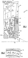
- FIG 1 schematically illustrates a simplified portion 10 of the turbine section of a gas turbine engine. Included within the portion shown is a turbine stator assembly 12 and a turbine rotor assembly 14.
- a flow path E for combustion gases is provided downstream of a combustion chamber (not shown) and defined in part by the stator assembly 12 including an annular outer flow path wall 17 and an annular inner flow path wall 19.
- the flow path E extends generally axially between alternating rows of stator vanes which form a stator vane section as represented by the single vane 18, and rows of rotor blades which form a rotor blade section as represented by the single blade 20.
- An annular cavity 24 is formed within the stator assembly 12 and it functions in part as a reservoir for turbine cooling air.
- the rotor blades 20 Downstream of the row of stator vanes 18 is disposed the row of rotor blades 20.
- the rotor blades 20 extend radially outwardly from a supporting rotor disk 26 via respective rotor blade roots 22 which are mounted in the supporting rotor disk 26.
- the supporting rotor disk 26 includes a plurality of axial inlets 28, each communicating with internal radial passages 23 of the root 22 and the blade 20. Only part of the passages 23 and their surface apertures within the blade 20 being shown, through which cooling air is flowable to the blade 20. After circulating through the passages 23, the cooling air discharges into the flow path E through a plurality of small apertures, forming a protective film over the blade's external surface.
- a rotor coverplate 30 is mounted upstream of the rotor disk 26 to rotate therewith.
- the rotor assembly 14 forms an annular and radial passage 34 between the rotor disk 26 and the rotor cover 30.
- a multitude of apertures 36 are located through the rotor coverplate 30.
- the apertures 36 communicate with the passage 34 for the intake of cooling air to the axial inlets 28.
- the multitude of coverplate apertures 36 are located through an angled annular section 38 of the rotor coverplate 30.
- a cooling air delivery structure in the form of an Angled On-Board Injection (AOBI) 40 includes a generally annular upstream wall 42, an annular downstream wall 44 and an annular body 46 which interconnects the upstream and downstream walls 42, 44.
- the upstream wall 42 and the downstream wall 44 interface with the inner flow path wall 19 such that cooling air discharged radially inward from the vane 18 is directed into the AOBI 40.
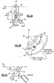
- the AOBI 40 may generally include a number of discrete nozzles, with each nozzle containing a radial nozzle section 40A and an angled nozzle section 40B.
- the angled nozzle section 40B defines a metering throat 41 angled radially inward and aftward.
- the AOBI 40 places the metering throat 41 at the inward angle A relative to an engine centerline W.
- the angled nozzle section 40B is located at a corresponding angle relative to the engine centerline W such that the nozzle discharge is aligned with the coverplate aperture.
- the AOBI allows for a flexible design which can be optimized such that the axial and radial packaging is minimized. That is, the AOBI 40 decouples the placement of the throat 41 from the placement of the coverplate apertures 36 which allows more flexibility in their placement and a more capable coverplate design.
- the angled annular section 38 may thereby be located at a smaller radius verses a TOBI to conserve radial height.
- the intersection of the flow exiting the nozzle 41, point a ( Figures 3A, 3B ), with the rotor coverplate aperture 36, point b, ( Figures 3A, 3B ) can be designed to require less radial spacing than a traditional TOBI.
- the AOBI 40 is located at a relatively small radius with the resulting benefit of lower cavity pressure requirements typical of a Radial On-Board Injector (ROBI).
- ROBI Radial On-Board Injector
- Lower loss coverplate apertures 36 may also be utilized because the coverplate apertures 36 are at a relatively larger radius about engine axis W than that required by a ROBI.
- the AOBI cavity 62 is defined in part by the angled annular section 38 having apertures 36. It should be understood that various seal arrangements may be readily integrated with the AOBI within a tightly packaged space.
- the optimum geometry is found when the constraints of the physical geometry are balanced with the need for an efficient cooling air system.
- the desire to have low cavity pressures and low-pressure losses dictates that the cooling air transfer has to occur at the smallest possible radius.
- the cross sectional area of the cooling holes, required to provide low pressure losses, combined with the need for acceptable structural margins in the rotating seal coverplate, dictate a minimum radius for the pattern of cooling holes.
- the shape of the cooling holes, quantity and pattern shape is optimized for structural and airflow needs.
- the physical dimensions of the two rotating turbine rotors 14 and 100 are determined by structural integrity requirements and the constraints of engine flowpath and overall engine length. They define the primary axial and radial zone for the cooling air system.
- the physical dimensions of typical high-speed seals, and the desire for redundancy establish additional axial and radial boundaries for where an AOBI can fit. Machining and casting tolerances combined with the required cooling airflow set the physical design constraints for the geometry of the AOBI:
- the optimum compound angle for the AOBI is a balance between targeting the cooling hole location, as it rotates away from the AOBI exhaust ports, and the axial and radial location of the AOBI nozzle.
- the air exiting the AOBI nozzle will intersect the rotating cooling hole at the design conditions where point a is the exit of a particular nozzle 41 and point b is the intersection point of cooling air exiting a particular nozzle element 41, point a, and the center of the coverplate aperture 36 such that the swirl velocity measured in the XY plane equals the rotational speed of apertures 36 and the cooling flow from point a to point b occurs with the least pressure loss ( Figures 3A and 3B ).
- the cooling system design provides: low cavity pressure gradients to the surrounding flowpath; minimal pressure losses; redundant seal configurations to avoid loss of cooling supply air; cooling air transfer between stationary hardware and the rotating hardware occur with the least losses; cooling air in the direction of the rotation, such that the cooling air velocity matches the rotational speed of the cooling hole; cooling air exiting from the AOBI to intersect the path of the rotating cooling holes, such that, at the design point, the cooling air vector is targeted at the center of the rotating cooling hole; and cooling air transport within the turbine rotor to occur with the least losses.
- the engine design disclosed herein provides: the shortest axial length possible within the confines of the optimal flowpath geometry; secondary structures, like the AOBI and stationary seals, to fit within the confines set by the primary structures such as the turbine rotors and vanes; and rotating seal coverplates to transport cooling air from the AOBI, to the turbine blade.
- cooling air from an upstream source flows through the annular outer flow path wall 17, the stator vane 18 and through the annular inner flow path wall 19. From the annular inner flow path wall 19, the cooling air is directed radially downward toward the engine centerline W between the upstream wall 42 and the downstream wall 44. The cooling air moves therebetween as the air flows toward the annular body 46.
- the cooling air enters a number of discrete nozzles by first entering into radial nozzle section 40A and then angled nozzle section 40B. The cooling air is injected from the AOBI 40 into the annular AOBI cavity 62 and enters apertures 36.
- the cooling air then flows radially outwardly through the passage 34, the axial inlets 28 through the radial passages 23, then cools the blade 20 as indicated by the arrows. After cooling the blade 20, the cooling air is discharged into the flow path E through a plurality of small apertures (not shown).
Landscapes
- Engineering & Computer Science (AREA)
- Mechanical Engineering (AREA)
- General Engineering & Computer Science (AREA)
- Chemical & Material Sciences (AREA)
- Combustion & Propulsion (AREA)
- Turbine Rotor Nozzle Sealing (AREA)
Claims (11)
- Structure de refroidissement pour moteur à turbine à gaz comprenant :une paroi amont (42) définie transversalement par rapport à un axe de moteur (W) ;une paroi aval (44) transversale par rapport audit axe de moteur (W) ;caractérisée en ce qu'elle comprend en outre :un corps annulaire (46) qui interconnecte ladite paroi amont (42) et ladite paroi aval (44) ;un injecteur embarqué incliné (40) se prolongeant à partir dudit corps (46), ledit injecteur (40) comprenant une section de buse radiale (40A) et une section de buse inclinée (40B) inclinée par rapport audit axe de moteur (W) ; etune plaque de recouvrement de rotor de turbine (30) comprenant une section annulaire inclinée (38), (38) inclinée par rapport audit axe de moteur (W), ladite plaque de recouvrement de rotor (30) présentant de multiples ouvertures (36) à travers ladite plaque de recouvrement de rotor (30) en communication fluidique avec ledit injecteur embarqué incliné (40),dans laquelle ladite section de buse inclinée (40B) est dirigée vers la plaque de recouvrement de rotor de turbine (30).
- Structure de refroidissement selon la revendication 1, dans laquelle ladite section de buse inclinée (40B) est inclinée entre approximativement 0 degré et 90 degrés par rapport audit axe de moteur (W).
- Structure de refroidissement selon la revendication 1 ou 2, dans laquelle ladite section de buse inclinée (40B) définit un orifice doseur (41).
- Structure de refroidissement selon une quelconque revendication précédente, dans laquelle ladite section annulaire inclinée (38) est transversale par rapport à ladite section de buse inclinée (40B).
- Structure de refroidissement selon une quelconque revendication précédente, comprenant en outre :un ensemble stator de turbine (12) défini autour dudit axe de moteur (W) ;dans laquelle ledit injecteur embarqué incliné (40) est en communication fluidique avec ledit ensemble stator de turbine (12) ; etun ensemble aube de turbine (14) adjacent audit ensemble stator de turbine (12), de sorte que ladite plaque de recouvrement de rotor (30) est montée en amont d'un disque de rotor (26) pour tourner avec.
- Structure de refroidissement selon la revendication 5, dans laquelle ledit injecteur embarqué incliné (40) est radialement à l'intérieur dudit ensemble stator (12).
- Structure de refroidissement selon la revendication 6, dans laquelle ladite section de buse inclinée (40B) est transversale par rapport audit injecteur embarqué incliné (40).
- Structure de refroidissement selon l'une quelconque des revendications 5 à 7, dans laquelle ladite section de buse inclinée (40B) est inclinée vers ledit ensemble aube de turbine (12).
- Structure de refroidissement selon l'une quelconque des revendications 5 à 8, dans laquelle ladite section de buse inclinée (40B) est inclinée radialement vers l'intérieur et vers ledit ensemble aube de turbine (14).
- Structure de refroidissement selon la revendication 5, dans laquelle ladite section annulaire inclinée (38) est généralement transversale par rapport à ladite section de buse inclinée (40B) de façon que lesdites multiples ouvertures (36) soient en communication fluidique avec ledit injecteur embarqué incliné (40).
- Structure de refroidissement selon la revendication 10, dans laquelle ladite section annulaire inclinée (38) est généralement perpendiculaire à ladite section de buse inclinée (40B).
Applications Claiming Priority (1)
| Application Number | Priority Date | Filing Date | Title |
|---|---|---|---|
| US11/772,335 US8562285B2 (en) | 2007-07-02 | 2007-07-02 | Angled on-board injector |
Publications (3)
| Publication Number | Publication Date |
|---|---|
| EP2011968A2 EP2011968A2 (fr) | 2009-01-07 |
| EP2011968A3 EP2011968A3 (fr) | 2012-08-29 |
| EP2011968B1 true EP2011968B1 (fr) | 2017-09-06 |
Family
ID=39790052
Family Applications (1)
| Application Number | Title | Priority Date | Filing Date |
|---|---|---|---|
| EP08252262.4A Active EP2011968B1 (fr) | 2007-07-02 | 2008-07-02 | Injecteur embarqué angulaire |
Country Status (2)
| Country | Link |
|---|---|
| US (1) | US8562285B2 (fr) |
| EP (1) | EP2011968B1 (fr) |
Families Citing this family (36)
| Publication number | Priority date | Publication date | Assignee | Title |
|---|---|---|---|---|
| US8408866B2 (en) * | 2008-11-17 | 2013-04-02 | Rolls-Royce Corporation | Apparatus and method for cooling a turbine airfoil arrangement in a gas turbine engine |
| US8529195B2 (en) | 2010-10-12 | 2013-09-10 | General Electric Company | Inducer for gas turbine system |
| EP2447543A1 (fr) * | 2010-10-27 | 2012-05-02 | Siemens Aktiengesellschaft | Compresseur axial et procédé de fonctionnement correspondant |
| GB201103890D0 (en) * | 2011-03-08 | 2011-04-20 | Rolls Royce Plc | Gas turbine engine swirled cooling air |
| US8899924B2 (en) | 2011-06-20 | 2014-12-02 | United Technologies Corporation | Non-mechanically fastened TOBI heat shield |
| US9068461B2 (en) * | 2011-08-18 | 2015-06-30 | Siemens Aktiengesellschaft | Turbine rotor disk inlet orifice for a turbine engine |
| CH705840A1 (de) * | 2011-12-06 | 2013-06-14 | Alstom Technology Ltd | Hochdruck-Verdichter, insbesondere in einer Gasturbine. |
| US9435259B2 (en) | 2012-02-27 | 2016-09-06 | United Technologies Corporation | Gas turbine engine cooling system |
| US9038398B2 (en) | 2012-02-27 | 2015-05-26 | United Technologies Corporation | Gas turbine engine buffer cooling system |
| US9347374B2 (en) | 2012-02-27 | 2016-05-24 | United Technologies Corporation | Gas turbine engine buffer cooling system |
| US9157325B2 (en) | 2012-02-27 | 2015-10-13 | United Technologies Corporation | Buffer cooling system providing gas turbine engine architecture cooling |
| US9175565B2 (en) * | 2012-08-03 | 2015-11-03 | General Electric Company | Systems and apparatus relating to seals for turbine engines |
| EP2964898B1 (fr) | 2013-03-06 | 2019-01-16 | Rolls-Royce North American Technologies, Inc. | Moteur de turbine à gaz à tuyère à pré-turbulence montée flexible |
| DE102013011350A1 (de) | 2013-07-08 | 2015-01-22 | Rolls-Royce Deutschland Ltd & Co Kg | Gasturbine mit Hochdruckturbinenkühlsystem |
| US10132193B2 (en) | 2013-08-19 | 2018-11-20 | United Technologies Corporation | Gas turbine engine duct assembly |
| US10233840B2 (en) * | 2014-04-25 | 2019-03-19 | United Technologies Corporation | Compressor injector apparatus and system |
| EP2980361B1 (fr) | 2014-07-28 | 2018-02-14 | United Technologies Corporation | Système de refroidissement d'un ensemble de stator pour un moteur à turbine à gaz ayant un mécanisme de débit de refroidissement variable et procédé de fonctionnement |
| US10443498B2 (en) * | 2014-08-15 | 2019-10-15 | United Technologies Corporation | Gas turbine engine cooling fluid metering system |
| EP2995778B1 (fr) * | 2014-09-12 | 2020-10-28 | United Technologies Corporation | Procédé et ensemble permettant de réduire la chaleur secondaire dans un moteur à turbine à gaz |
| US10077666B2 (en) * | 2014-09-23 | 2018-09-18 | United Technologies Corporation | Method and assembly for reducing secondary heat in a gas turbine engine |
| EP3020929A1 (fr) | 2014-11-17 | 2016-05-18 | United Technologies Corporation | Ensemble joint de bordure pour plate-forme portante |
| EP3034837B1 (fr) * | 2014-12-17 | 2017-10-11 | MTU Aero Engines GmbH | Dispositif d'alimentation d'air de refroidissement pour une turbine à gaz |
| US9771814B2 (en) | 2015-03-09 | 2017-09-26 | United Technologies Corporation | Tolerance resistance coverplates |
| GB2536628A (en) * | 2015-03-19 | 2016-09-28 | Rolls Royce Plc | HPT Integrated interstage seal and cooling air passageways |
| EP3124743B1 (fr) * | 2015-07-28 | 2021-04-28 | Rolls-Royce Deutschland Ltd & Co KG | Aube de distributeur et procédé de fabrication d'une aube de distributeur |
| US9970299B2 (en) * | 2015-09-16 | 2018-05-15 | General Electric Company | Mixing chambers for turbine wheel space cooling |
| US10125632B2 (en) | 2015-10-20 | 2018-11-13 | General Electric Company | Wheel space purge flow mixing chamber |
| US10132195B2 (en) | 2015-10-20 | 2018-11-20 | General Electric Company | Wheel space purge flow mixing chamber |
| US10030538B2 (en) * | 2015-11-05 | 2018-07-24 | General Electric Company | Gas turbine engine with a vane having a cooling air turning nozzle |
| US10519873B2 (en) | 2016-04-06 | 2019-12-31 | General Electric Company | Air bypass system for rotor shaft cooling |
| JP7004595B2 (ja) * | 2018-03-09 | 2022-01-21 | 三菱重工業株式会社 | インペラ、遠心圧縮機、及びガスタービン |
| US11105212B2 (en) * | 2019-01-29 | 2021-08-31 | Honeywell International Inc. | Gas turbine engines including tangential on-board injectors and methods for manufacturing the same |
| FR3108661B1 (fr) * | 2020-03-25 | 2022-09-02 | Safran Aircraft Engines | Couronne d’injecteurs de turbine |
| CN112049688B (zh) * | 2020-08-19 | 2021-08-10 | 西北工业大学 | 一种用于等半径预旋供气系统的过预旋叶型接受孔 |
| US11859550B2 (en) * | 2021-04-01 | 2024-01-02 | General Electric Company | Compound angle accelerator |
| US11746675B2 (en) | 2021-11-23 | 2023-09-05 | Rolls-Royce Corporation | Vane ring assembly for a gas turbine engine with dedicated through-flow vanes |
Family Cites Families (35)
| Publication number | Priority date | Publication date | Assignee | Title |
|---|---|---|---|---|
| US4526511A (en) | 1982-11-01 | 1985-07-02 | United Technologies Corporation | Attachment for TOBI |
| US4709545A (en) | 1983-05-31 | 1987-12-01 | United Technologies Corporation | Bearing compartment protection system |
| DE3514352A1 (de) * | 1985-04-20 | 1986-10-23 | MTU Motoren- und Turbinen-Union München GmbH, 8000 München | Gasturbinentriebwerk mit einrichtungen zur abzweigung von verdichterluft zur kuehlung von heissteilen |
| US4822244A (en) | 1987-10-15 | 1989-04-18 | United Technologies Corporation | Tobi |
| US4872810A (en) | 1988-12-14 | 1989-10-10 | United Technologies Corporation | Turbine rotor retention system |
| US5310319A (en) | 1993-01-12 | 1994-05-10 | United Technologies Corporation | Free standing turbine disk sideplate assembly |
| US5358374A (en) * | 1993-07-21 | 1994-10-25 | General Electric Company | Turbine nozzle backflow inhibitor |
| US5484258A (en) | 1994-03-01 | 1996-01-16 | General Electric Company | Turbine airfoil with convectively cooled double shell outer wall |
| US5522698A (en) | 1994-04-29 | 1996-06-04 | United Technologies Corporation | Brush seal support and vane assembly windage cover |
| US5597167A (en) | 1994-09-28 | 1997-01-28 | United Technologies Corporation | Brush seal with fool proofing and anti-rotation tab |
| US5645397A (en) | 1995-10-10 | 1997-07-08 | United Technologies Corporation | Turbine vane assembly with multiple passage cooled vanes |
| US5996331A (en) * | 1997-09-15 | 1999-12-07 | Alliedsignal Inc. | Passive turbine coolant regulator responsive to engine load |
| DE19824766C2 (de) * | 1998-06-03 | 2000-05-11 | Siemens Ag | Gasturbine sowie Verfahren zur Kühlung einer Turbinenstufe |
| US6227801B1 (en) | 1999-04-27 | 2001-05-08 | Pratt & Whitney Canada Corp. | Turbine engine having improved high pressure turbine cooling |
| US6183193B1 (en) | 1999-05-21 | 2001-02-06 | Pratt & Whitney Canada Corp. | Cast on-board injection nozzle with adjustable flow area |
| US6267553B1 (en) | 1999-06-01 | 2001-07-31 | Joseph C. Burge | Gas turbine compressor spool with structural and thermal upgrades |
| DE10034563A1 (de) | 2000-07-14 | 2002-01-24 | Basf Ag | Federelement |
| US6398488B1 (en) * | 2000-09-13 | 2002-06-04 | General Electric Company | Interstage seal cooling |
| US6722138B2 (en) | 2000-12-13 | 2004-04-20 | United Technologies Corporation | Vane platform trailing edge cooling |
| US6468032B2 (en) | 2000-12-18 | 2002-10-22 | Pratt & Whitney Canada Corp. | Further cooling of pre-swirl flow entering cooled rotor aerofoils |
| US6540477B2 (en) * | 2001-05-21 | 2003-04-01 | General Electric Company | Turbine cooling circuit |
| US6647730B2 (en) | 2001-10-31 | 2003-11-18 | Pratt & Whitney Canada Corp. | Turbine engine having turbine cooled with diverted compressor intermediate pressure air |
| US6773225B2 (en) | 2002-05-30 | 2004-08-10 | Mitsubishi Heavy Industries, Ltd. | Gas turbine and method of bleeding gas therefrom |
| US6655906B1 (en) | 2002-05-30 | 2003-12-02 | Mitsubishi Heavy Industries, Ltd. | Axial compressor and gas bleeding method to thrust balance disk thereof |
| US6837676B2 (en) | 2002-09-11 | 2005-01-04 | Mitsubishi Heavy Industries, Ltd. | Gas turbine |
| DE60201324T2 (de) * | 2002-11-07 | 2005-10-06 | Snecma Moteurs | Stator für eine Turbomaschine |
| US7017349B2 (en) | 2003-02-05 | 2006-03-28 | Mitsubishi Heavy Industries, Ltd. | Gas turbine and bleeding method thereof |
| FR2851010B1 (fr) * | 2003-02-06 | 2005-04-15 | Snecma Moteurs | Dispositif de ventilation d'un rotor de turbine a haute pression d'une turbomachine |
| US6974306B2 (en) | 2003-07-28 | 2005-12-13 | Pratt & Whitney Canada Corp. | Blade inlet cooling flow deflector apparatus and method |
| US6969237B2 (en) | 2003-08-28 | 2005-11-29 | United Technologies Corporation | Turbine airfoil cooling flow particle separator |
| US7090461B2 (en) | 2003-10-30 | 2006-08-15 | Siemens Westinghouse Power Corporation | Gas turbine vane with integral cooling flow control system |
| GB2413598A (en) * | 2004-05-01 | 2005-11-02 | Rolls Royce Plc | Providing cooling gas to turbine blade and disc in gas turbine engine |
| US7118326B2 (en) | 2004-06-17 | 2006-10-10 | Siemens Power Generation, Inc. | Cooled gas turbine vane |
| GB2426289B (en) * | 2005-04-01 | 2007-07-04 | Rolls Royce Plc | Cooling system for a gas turbine engine |
| GB0524929D0 (en) * | 2005-12-06 | 2006-01-18 | Rolls Royce Plc | Retention arrangement |
-
2007
- 2007-07-02 US US11/772,335 patent/US8562285B2/en active Active
-
2008
- 2008-07-02 EP EP08252262.4A patent/EP2011968B1/fr active Active
Non-Patent Citations (1)
| Title |
|---|
| None * |
Also Published As
| Publication number | Publication date |
|---|---|
| EP2011968A2 (fr) | 2009-01-07 |
| EP2011968A3 (fr) | 2012-08-29 |
| US8562285B2 (en) | 2013-10-22 |
| US20090010751A1 (en) | 2009-01-08 |
Similar Documents
| Publication | Publication Date | Title |
|---|---|---|
| EP2011968B1 (fr) | Injecteur embarqué angulaire | |
| CN107448300B (zh) | 用于涡轮发动机的翼型件 | |
| EP1022432B1 (fr) | Aube de turbine à gaz refroidie | |
| US7008185B2 (en) | Gas turbine engine turbine nozzle bifurcated impingement baffle | |
| EP1205636B1 (fr) | Aube de turbine à gaz et procédé de refroidissement d'une telle aube | |
| US9528377B2 (en) | Method and system for cooling rotor blade angelwings | |
| EP3081753B1 (fr) | Agencement de refroidissement de pointe de lame | |
| EP3329099B1 (fr) | Agencements de refroidissement dans des aubes de turbine | |
| EP0702748A1 (fr) | Aube de rotor a plateforme integrale refroidie | |
| EP3399149B1 (fr) | Couvercles de dérivation pour aubes dans des moteurs à turbine à gaz | |
| US10648342B2 (en) | Engine component with cooling hole | |
| EP1709299A1 (fr) | Turbine a gaz comprenant des profils aerodynamiques presentant une configuration de refroidissement par gaine d'air amelioree et procede afferent | |
| US6357999B1 (en) | Gas turbine engine internal air system | |
| CN108868898A (zh) | 用于冷却涡轮发动机的翼型件顶端的设备和方法 | |
| WO2017196469A2 (fr) | Surface portante à circuit de refroidissement | |
| EP3690189B1 (fr) | Paroi d'extrémité profilée pour un moteur à turbine à gaz | |
| CA3010385A1 (fr) | Protecteur de profil dynamique de moteur de turbine | |
| CN113123878A (zh) | 不同α的可变面积计量 | |
| EP3561230B1 (fr) | Composants de moteur de turbine à gaz avec cavités en spirale de flux de refroidissement | |
| CN109563742A (zh) | 具有多孔式孔的发动机构件 | |
| CA3055848A1 (fr) | Ensemble d`injection tangentielle de bord (tobi) | |
| EP3392457B1 (fr) | Turbine avec injecteur de bord tangentiel tourné vers l'amont | |
| CN110735664A (zh) | 用于具有冷却孔的涡轮发动机的部件 | |
| CN108506048A (zh) | 用于涡轮发动机的膜孔布置 | |
| EP3508693B1 (fr) | Passages d'air de refroidissement séparés pour aube de turbine |
Legal Events
| Date | Code | Title | Description |
|---|---|---|---|
| PUAI | Public reference made under article 153(3) epc to a published international application that has entered the european phase |
Free format text: ORIGINAL CODE: 0009012 |
|
| AK | Designated contracting states |
Kind code of ref document: A2 Designated state(s): AT BE BG CH CY CZ DE DK EE ES FI FR GB GR HR HU IE IS IT LI LT LU LV MC MT NL NO PL PT RO SE SI SK TR |
|
| AX | Request for extension of the european patent |
Extension state: AL BA MK RS |
|
| PUAL | Search report despatched |
Free format text: ORIGINAL CODE: 0009013 |
|
| AK | Designated contracting states |
Kind code of ref document: A3 Designated state(s): AT BE BG CH CY CZ DE DK EE ES FI FR GB GR HR HU IE IS IT LI LT LU LV MC MT NL NO PL PT RO SE SI SK TR |
|
| AX | Request for extension of the european patent |
Extension state: AL BA MK RS |
|
| RIC1 | Information provided on ipc code assigned before grant |
Ipc: F01D 5/08 20060101AFI20120726BHEP |
|
| 17P | Request for examination filed |
Effective date: 20130228 |
|
| AKX | Designation fees paid |
Designated state(s): DE GB |
|
| RAP1 | Party data changed (applicant data changed or rights of an application transferred) |
Owner name: UNITED TECHNOLOGIES CORPORATION |
|
| REG | Reference to a national code |
Ref country code: DE Ref legal event code: R079 Ref document number: 602008051992 Country of ref document: DE Free format text: PREVIOUS MAIN CLASS: F01D0005080000 Ipc: F02C0007280000 |
|
| GRAP | Despatch of communication of intention to grant a patent |
Free format text: ORIGINAL CODE: EPIDOSNIGR1 |
|
| RIC1 | Information provided on ipc code assigned before grant |
Ipc: F02C 7/28 20060101AFI20170228BHEP Ipc: F01D 5/08 20060101ALI20170228BHEP |
|
| INTG | Intention to grant announced |
Effective date: 20170329 |
|
| GRAS | Grant fee paid |
Free format text: ORIGINAL CODE: EPIDOSNIGR3 |
|
| GRAA | (expected) grant |
Free format text: ORIGINAL CODE: 0009210 |
|
| AK | Designated contracting states |
Kind code of ref document: B1 Designated state(s): DE GB |
|
| REG | Reference to a national code |
Ref country code: GB Ref legal event code: FG4D |
|
| REG | Reference to a national code |
Ref country code: DE Ref legal event code: R096 Ref document number: 602008051992 Country of ref document: DE |
|
| REG | Reference to a national code |
Ref country code: DE Ref legal event code: R097 Ref document number: 602008051992 Country of ref document: DE |
|
| PLBE | No opposition filed within time limit |
Free format text: ORIGINAL CODE: 0009261 |
|
| STAA | Information on the status of an ep patent application or granted ep patent |
Free format text: STATUS: NO OPPOSITION FILED WITHIN TIME LIMIT |
|
| 26N | No opposition filed |
Effective date: 20180607 |
|
| REG | Reference to a national code |
Ref country code: DE Ref legal event code: R081 Ref document number: 602008051992 Country of ref document: DE Owner name: RAYTHEON TECHNOLOGIES CORPORATION (N.D.GES.D.S, US Free format text: FORMER OWNER: UNITED TECHNOLOGIES CORPORATION, FARMINGTON, CONN., US |
|
| P01 | Opt-out of the competence of the unified patent court (upc) registered |
Effective date: 20230519 |
|
| PGFP | Annual fee paid to national office [announced via postgrant information from national office to epo] |
Ref country code: GB Payment date: 20230620 Year of fee payment: 16 |
|
| PGFP | Annual fee paid to national office [announced via postgrant information from national office to epo] |
Ref country code: DE Payment date: 20230620 Year of fee payment: 16 |