EP2011570A1 - Exhaust gas purifying catalyst, method for recovering exhaust gas purifying catalyst, and catalyst system for exhaust gas purification - Google Patents
Exhaust gas purifying catalyst, method for recovering exhaust gas purifying catalyst, and catalyst system for exhaust gas purification Download PDFInfo
- Publication number
- EP2011570A1 EP2011570A1 EP07742073A EP07742073A EP2011570A1 EP 2011570 A1 EP2011570 A1 EP 2011570A1 EP 07742073 A EP07742073 A EP 07742073A EP 07742073 A EP07742073 A EP 07742073A EP 2011570 A1 EP2011570 A1 EP 2011570A1
- Authority
- EP
- European Patent Office
- Prior art keywords
- exhaust gas
- gas purifying
- purifying catalyst
- catalyst
- oxide
- Prior art date
- Legal status (The legal status is an assumption and is not a legal conclusion. Google has not performed a legal analysis and makes no representation as to the accuracy of the status listed.)
- Withdrawn
Links
Images



Classifications
-
- B—PERFORMING OPERATIONS; TRANSPORTING
- B01—PHYSICAL OR CHEMICAL PROCESSES OR APPARATUS IN GENERAL
- B01D—SEPARATION
- B01D53/00—Separation of gases or vapours; Recovering vapours of volatile solvents from gases; Chemical or biological purification of waste gases, e.g. engine exhaust gases, smoke, fumes, flue gases, aerosols
- B01D53/34—Chemical or biological purification of waste gases
- B01D53/92—Chemical or biological purification of waste gases of engine exhaust gases
- B01D53/94—Chemical or biological purification of waste gases of engine exhaust gases by catalytic processes
- B01D53/9445—Simultaneously removing carbon monoxide, hydrocarbons or nitrogen oxides making use of three-way catalysts [TWC] or four-way-catalysts [FWC]
- B01D53/945—Simultaneously removing carbon monoxide, hydrocarbons or nitrogen oxides making use of three-way catalysts [TWC] or four-way-catalysts [FWC] characterised by a specific catalyst
-
- B—PERFORMING OPERATIONS; TRANSPORTING
- B01—PHYSICAL OR CHEMICAL PROCESSES OR APPARATUS IN GENERAL
- B01J—CHEMICAL OR PHYSICAL PROCESSES, e.g. CATALYSIS OR COLLOID CHEMISTRY; THEIR RELEVANT APPARATUS
- B01J23/00—Catalysts comprising metals or metal oxides or hydroxides, not provided for in group B01J21/00
- B01J23/38—Catalysts comprising metals or metal oxides or hydroxides, not provided for in group B01J21/00 of noble metals
- B01J23/54—Catalysts comprising metals or metal oxides or hydroxides, not provided for in group B01J21/00 of noble metals combined with metals, oxides or hydroxides provided for in groups B01J23/02 - B01J23/36
- B01J23/56—Platinum group metals
- B01J23/63—Platinum group metals with rare earths or actinides
-
- B—PERFORMING OPERATIONS; TRANSPORTING
- B01—PHYSICAL OR CHEMICAL PROCESSES OR APPARATUS IN GENERAL
- B01D—SEPARATION
- B01D53/00—Separation of gases or vapours; Recovering vapours of volatile solvents from gases; Chemical or biological purification of waste gases, e.g. engine exhaust gases, smoke, fumes, flue gases, aerosols
- B01D53/34—Chemical or biological purification of waste gases
- B01D53/74—General processes for purification of waste gases; Apparatus or devices specially adapted therefor
- B01D53/86—Catalytic processes
-
- B—PERFORMING OPERATIONS; TRANSPORTING
- B01—PHYSICAL OR CHEMICAL PROCESSES OR APPARATUS IN GENERAL
- B01D—SEPARATION
- B01D53/00—Separation of gases or vapours; Recovering vapours of volatile solvents from gases; Chemical or biological purification of waste gases, e.g. engine exhaust gases, smoke, fumes, flue gases, aerosols
- B01D53/34—Chemical or biological purification of waste gases
- B01D53/92—Chemical or biological purification of waste gases of engine exhaust gases
- B01D53/94—Chemical or biological purification of waste gases of engine exhaust gases by catalytic processes
-
- B—PERFORMING OPERATIONS; TRANSPORTING
- B01—PHYSICAL OR CHEMICAL PROCESSES OR APPARATUS IN GENERAL
- B01J—CHEMICAL OR PHYSICAL PROCESSES, e.g. CATALYSIS OR COLLOID CHEMISTRY; THEIR RELEVANT APPARATUS
- B01J23/00—Catalysts comprising metals or metal oxides or hydroxides, not provided for in group B01J21/00
- B01J23/38—Catalysts comprising metals or metal oxides or hydroxides, not provided for in group B01J21/00 of noble metals
- B01J23/54—Catalysts comprising metals or metal oxides or hydroxides, not provided for in group B01J21/00 of noble metals combined with metals, oxides or hydroxides provided for in groups B01J23/02 - B01J23/36
- B01J23/56—Platinum group metals
- B01J23/58—Platinum group metals with alkali- or alkaline earth metals
-
- B—PERFORMING OPERATIONS; TRANSPORTING
- B01—PHYSICAL OR CHEMICAL PROCESSES OR APPARATUS IN GENERAL
- B01J—CHEMICAL OR PHYSICAL PROCESSES, e.g. CATALYSIS OR COLLOID CHEMISTRY; THEIR RELEVANT APPARATUS
- B01J37/00—Processes, in general, for preparing catalysts; Processes, in general, for activation of catalysts
- B01J37/02—Impregnation, coating or precipitation
- B01J37/0234—Impregnation and coating simultaneously
-
- B—PERFORMING OPERATIONS; TRANSPORTING
- B01—PHYSICAL OR CHEMICAL PROCESSES OR APPARATUS IN GENERAL
- B01J—CHEMICAL OR PHYSICAL PROCESSES, e.g. CATALYSIS OR COLLOID CHEMISTRY; THEIR RELEVANT APPARATUS
- B01J38/00—Regeneration or reactivation of catalysts, in general
- B01J38/04—Gas or vapour treating; Treating by using liquids vaporisable upon contacting spent catalyst
-
- B—PERFORMING OPERATIONS; TRANSPORTING
- B01—PHYSICAL OR CHEMICAL PROCESSES OR APPARATUS IN GENERAL
- B01D—SEPARATION
- B01D2255/00—Catalysts
- B01D2255/10—Noble metals or compounds thereof
-
- B—PERFORMING OPERATIONS; TRANSPORTING
- B01—PHYSICAL OR CHEMICAL PROCESSES OR APPARATUS IN GENERAL
- B01D—SEPARATION
- B01D2255/00—Catalysts
- B01D2255/20—Metals or compounds thereof
- B01D2255/204—Alkaline earth metals
-
- B—PERFORMING OPERATIONS; TRANSPORTING
- B01—PHYSICAL OR CHEMICAL PROCESSES OR APPARATUS IN GENERAL
- B01D—SEPARATION
- B01D2255/00—Catalysts
- B01D2255/20—Metals or compounds thereof
- B01D2255/206—Rare earth metals
-
- B—PERFORMING OPERATIONS; TRANSPORTING
- B01—PHYSICAL OR CHEMICAL PROCESSES OR APPARATUS IN GENERAL
- B01J—CHEMICAL OR PHYSICAL PROCESSES, e.g. CATALYSIS OR COLLOID CHEMISTRY; THEIR RELEVANT APPARATUS
- B01J23/00—Catalysts comprising metals or metal oxides or hydroxides, not provided for in group B01J21/00
- B01J23/002—Mixed oxides other than spinels, e.g. perovskite
-
- B—PERFORMING OPERATIONS; TRANSPORTING
- B01—PHYSICAL OR CHEMICAL PROCESSES OR APPARATUS IN GENERAL
- B01J—CHEMICAL OR PHYSICAL PROCESSES, e.g. CATALYSIS OR COLLOID CHEMISTRY; THEIR RELEVANT APPARATUS
- B01J2523/00—Constitutive chemical elements of heterogeneous catalysts
- B01J2523/20—Constitutive chemical elements of heterogeneous catalysts of Group II (IIA or IIB) of the Periodic Table
- B01J2523/22—Magnesium
-
- B—PERFORMING OPERATIONS; TRANSPORTING
- B01—PHYSICAL OR CHEMICAL PROCESSES OR APPARATUS IN GENERAL
- B01J—CHEMICAL OR PHYSICAL PROCESSES, e.g. CATALYSIS OR COLLOID CHEMISTRY; THEIR RELEVANT APPARATUS
- B01J2523/00—Constitutive chemical elements of heterogeneous catalysts
- B01J2523/30—Constitutive chemical elements of heterogeneous catalysts of Group III (IIIA or IIIB) of the Periodic Table
- B01J2523/31—Aluminium
-
- B—PERFORMING OPERATIONS; TRANSPORTING
- B01—PHYSICAL OR CHEMICAL PROCESSES OR APPARATUS IN GENERAL
- B01J—CHEMICAL OR PHYSICAL PROCESSES, e.g. CATALYSIS OR COLLOID CHEMISTRY; THEIR RELEVANT APPARATUS
- B01J2523/00—Constitutive chemical elements of heterogeneous catalysts
- B01J2523/30—Constitutive chemical elements of heterogeneous catalysts of Group III (IIIA or IIIB) of the Periodic Table
- B01J2523/37—Lanthanides
- B01J2523/3718—Praseodymium
-
- B—PERFORMING OPERATIONS; TRANSPORTING
- B01—PHYSICAL OR CHEMICAL PROCESSES OR APPARATUS IN GENERAL
- B01J—CHEMICAL OR PHYSICAL PROCESSES, e.g. CATALYSIS OR COLLOID CHEMISTRY; THEIR RELEVANT APPARATUS
- B01J2523/00—Constitutive chemical elements of heterogeneous catalysts
- B01J2523/30—Constitutive chemical elements of heterogeneous catalysts of Group III (IIIA or IIIB) of the Periodic Table
- B01J2523/37—Lanthanides
- B01J2523/3725—Neodymium
-
- B—PERFORMING OPERATIONS; TRANSPORTING
- B01—PHYSICAL OR CHEMICAL PROCESSES OR APPARATUS IN GENERAL
- B01J—CHEMICAL OR PHYSICAL PROCESSES, e.g. CATALYSIS OR COLLOID CHEMISTRY; THEIR RELEVANT APPARATUS
- B01J2523/00—Constitutive chemical elements of heterogeneous catalysts
- B01J2523/40—Constitutive chemical elements of heterogeneous catalysts of Group IV (IVA or IVB) of the Periodic Table
- B01J2523/48—Zirconium
-
- B—PERFORMING OPERATIONS; TRANSPORTING
- B01—PHYSICAL OR CHEMICAL PROCESSES OR APPARATUS IN GENERAL
- B01J—CHEMICAL OR PHYSICAL PROCESSES, e.g. CATALYSIS OR COLLOID CHEMISTRY; THEIR RELEVANT APPARATUS
- B01J37/00—Processes, in general, for preparing catalysts; Processes, in general, for activation of catalysts
- B01J37/02—Impregnation, coating or precipitation
- B01J37/03—Precipitation; Co-precipitation
-
- Y—GENERAL TAGGING OF NEW TECHNOLOGICAL DEVELOPMENTS; GENERAL TAGGING OF CROSS-SECTIONAL TECHNOLOGIES SPANNING OVER SEVERAL SECTIONS OF THE IPC; TECHNICAL SUBJECTS COVERED BY FORMER USPC CROSS-REFERENCE ART COLLECTIONS [XRACs] AND DIGESTS
- Y02—TECHNOLOGIES OR APPLICATIONS FOR MITIGATION OR ADAPTATION AGAINST CLIMATE CHANGE
- Y02T—CLIMATE CHANGE MITIGATION TECHNOLOGIES RELATED TO TRANSPORTATION
- Y02T10/00—Road transport of goods or passengers
- Y02T10/10—Internal combustion engine [ICE] based vehicles
- Y02T10/12—Improving ICE efficiencies
Definitions
- the present invention relates to an exhaust gas purifying catalyst that removes toxic substances contained in exhaust gas from an internal combustion engine of an automobile, a motorcycle, and others.
- the present invention also relates to a method for recovering the exhaust gas purifying catalyst, and a catalyst system.
- an exhaust gas purifying catalyst for use in an automobile or the like is known to include an oxide of alkali earth and rare earth supported by a noble metal such as Pt, Rh, Pd, and others.
- Patent Literature 1 Unexamined Japanese Patent Publication No. 8-144748
- the exhaust gas temperature in the oxidation treatment process is low when the above method for recovering the catalyst is performed, the noble metal remains coagulated. Moreover, different from the case of temporary deterioration, the catalytic performance has sometimes never been recovered. Therefore, there is a problem that the exhaust gas temperature must be strictly controlled when the oxidation treatment process is performed. Especially in a diesel engine, the exhaust gas temperature seldom becomes 600°C or above at normal driving in an urban area. It was difficult to apply the recovery method to a diesel vehicle.
- An object of the present invention is to provide an exhaust gas purifying catalyst that can recover the catalytic activity over a wide temperature range, a method of recovering an exhaust gas purifying catalyst, and a catalyst system for exhaust gas purification.
- the invention according to claim 1 provides an exhaust gas purifying catalyst which includes: an oxide A containing an oxide (A-1) containing an alkaline earth metal and/or a rare earth metal and an inorganic oxide (A-2); and a noble metal B supported by the oxide A.
- a weight ratio of the noble metal B to the oxide (A-1) containing an alkaline earth metal and/or a rare earth metal is from 1:10 to 1:300.
- the exhaust gas purifying catalyst of the present invention has the aforementioned composition, especially, the weight ratio of the noble metal B to the oxide (A-1) is from 1:10 to 1:300 (preferably from 1:30 to 1:200).
- the exhaust gas purifying catalyst of the present invention can inhibit coagulation of noble metal particles and recover the catalytic performance even if the catalyst temperature at an oxidation treatment process is low (600°C or below, for example) when a recovery method is conducted. Accordingly, the exhaust gas purifying catalyst of the present invention can recover the catalytic activity by performing the oxidation treatment process by the exhaust gas having a temperature of 600°C or below.
- the exhaust gas temperature of an internal combustion engine is usually 600°C or below. That is, in the case of a gasoline vehicle, the frequency at which the exhaust gas temperature becomes 600°C or above at normal driving is very low in view of all the driving zones. Especially if there is high frequency of driving in a suburb, the exhaust gas temperature seldom reaches 600°C. Also, in the case of a diesel vehicle, the exhaust gas temperature is further low as compared to the case of a gasoline vehicle by 100°C. It is extremely rare that the exhaust gas temperature goes up to 600°C or above.
- the oxidation treatment process can be performed at low temperature. Accordingly, the oxidation treatment process can be performed by an exhaust gas having a temperature of 600°C or below to recover the catalytic activity. Therefore, there is no need for raising the catalyst temperature all the way up to 600°C or above upon performing the oxidation treatment process. There is an effect in that recovery is easy.
- the oxide (A-1) may be composed of one or both of the alkaline earth oxide and the rare earth metal oxide, or may further include another oxide other than the alkaline earth oxide and the rare earth metal oxide.
- the oxide (A-1) may be a compound having a crystal structure such as ABO 3 (perovskite), AB 2 O 4 (spinel), and others.
- Examples of the inorganic oxide (A-2) are other than the oxide (A-1), particularly one or more of those selected from a group consisting of Al 2 O 3 , SiO 2 , ZrO 2 , TiO 2 and zeolite.
- Examples of the noble metal may be one or more of those selected from a group consisting of Pt, Pd, Rh and Ir.
- a preferable amount of the noble metal to be mixed is in a range from 0.1 to 3 g/L. Sufficient catalytic performance can be achieved if the amount of the noble metal to be mixed is 0.1 g/L or above. Increase in cost can be avoided if the amount of the noble metal to be mixed is 3 g/L or below.
- the weight ratio of the noble metal B to the oxide (A-1) is 1:10 to 1:300, more preferably 1:30 to 1:200. If the weight ratio of the noble metal B to the oxide (A-1) is 1:10 (preferably 1:30) or above, the noble metal B can hardly exist excessively. Thus, interaction between the oxide (A-1) and the noble metal B is strengthened. Effect in inhibiting coagulation of the noble metal B is enhanced. Also, if the weight ratio of the noble mental B to the oxide (A-1) is 1:300 (preferably 1:200) or below, effect in interaction between the oxide (A-1) and the noble metal B is large. Effect in inhibiting coagulation of the noble metal is enhanced.
- the invention according to claim 2 provides the exhaust gas purifying catalyst as set forth in claim 1 wherein the inorganic oxide (A-2) contains one or more of those selected from a group consisting of Al 2 O 3 , SiO 2 , ZrO 2 , TiO 2 and zeolite.
- the exhaust gas purifying catalyst of the present invention can recover the catalytic performance all the more effectively since the inorganic oxide (A-2) is one or more of the above.
- the invention according to claim 3 provides a method for recovering an exhaust gas purifying catalyst, which includes an oxidation treatment process that applies an oxidation treatment to the exhaust gas purifying catalyst as set forth in one of claims 1 to 3 by a lean state exhaust gas and a reduction treatment process that applies a reduction treatment to the exhaust gas purifying catalyst by a rich state exhaust gas.
- the catalytic performance of the exhaust gas purifying catalyst can be recovered.
- the lean state indicates a state of excessive air as compared to a stoichiometric state.
- the A/F ratio is 14.6 or more in the case of a gasoline engine, and 14.5 or more in the case of a diesel engine.
- the rich state indicates a state of excessive fuel as compared to a stoichiometric state.
- the A/F ratio is 14.6 or less in the case of a gasoline engine, and 14.5 or less in the case of a diesel engine.
- the time period for the reduction treatment process may be a spike-like processing time of about 0.1 sec, or may have a long duration of several hours.
- Patterns of the oxidation treatment process and the reduction treatment process may be as shown in FIGS. 3 and 4 , for example, that is, a section of the oxidation treatment process and a section of the reduction treatment process may be periodically switched over at certain timings so that the A/F ratios in each section may be constant. Or, as shown in FIG. 5 , the A/F ratio may be periodically changed little by little (for example, according to a sign curve) to form the oxidation treatment process and the reduction treatment process.
- the percentage of the time period for which the oxidation treatment process continues in the overall time period for which the recovery method is conducted is preferably in a range of 60 to 80%.
- the percentage of the time period for which the reduction treatment process continues is preferably in a range of 10 to 30%.
- an exhaust gas under rich conditions by rich spike and S (sulphur) regeneration can be used, for example in the case of the exhaust gas purifying catalyst provided in a direct gasoline injection vehicle.
- an exhaust gas under rich conditions by post injection, HC addition in exhaust system, rich spike and S regeneration can be used.
- the invention according to claim 4 provides the method for recovering an exhaust gas purifying catalyst as set forth in claim 3 wherein a temperature of the exhaust gas purifying catalyst in the reduction treatment process is set from 200 to 900°C.
- the recovery method of the present invention can increase a reducing action of noble metal and sufficiently recover the catalytic performance since the catalyst temperature in the reduction treatment process is set to 200°C or above (more preferably 500°C or above). Also, reducing effect is not decreased by excessive heat since the catalyst temperature in the reduction treatment process is set to 900°C or below (more preferably 600°C or below).
- the invention according to claim 5 provides the method for recovering an exhaust gas purifying catalyst as set forth in claim 3 or 4 wherein a temperature of the exhaust gas purifying catalyst in the oxidation treatment process is set from 200 to 600°C.
- the recovery method of the present invention can sufficiently recover the catalytic performance since the catalyst temperature in the oxidation treatment process is set to 200°C or above (more preferably 300°C or above). Also, the recovery method of the present invention can execute the oxidation treatment process by an exhaust gas having a temperature of 600°C or below and recover the catalytic activity since the catalyst temperature in the oxidation treatment process is 600°C or below (more preferably 500°C or below). Accordingly, there is no need of raising the catalyst temperature all the way up to 600°C or above when the oxidation treatment process is performed. There is effect in that recovery is easy.
- the invention according to claim 6 provides a catalyst system for exhaust gas purification, including the exhaust gas purifying catalyst as set forth in claim 1 or 2, a supply unit that supplies an exhaust gas to the exhaust gas purifying catalyst, and a control unit that can control the exhaust gas into either a lean or rich state.
- the exhaust gas may be controlled into a lean state by the control unit to perform the oxidation treatment process to the exhaust gas purifying catalyst. Also, the exhaust gas may be controlled into a rich state to perform the reduction treatment process to the exhaust gas purifying catalyst. That is, the catalyst system of the present invention can maintain the catalytic performance for a long term while recovering the catalytic performance of the exhaust gas purifying catalyst provided therein.
- An example of the supply unit may be an internal combustion engine for a gasoline engine and a diesel engine.
- control unit may be a computer that controls the state (rotary torque, for example) of the internal combustion engine.
- the invention according to claim 7 provides the catalyst system for exhaust gas purification as set forth in claim 6, wherein the control unit controls a temperature of the exhaust gas purifying catalyst into 200 to 900°C when the exhaust gas is in the rich state.
- the catalyst temperature is 200°C or above (more preferably 300°C or above) when the exhaust gas is in the rich state. Thus, a reducing action of noble metal is increased. The catalytic performance can be sufficiently recovered. Also, the catalyst temperature is 900°C or below (more preferably 600°C or below) when the exhaust gas is in the rich state. Thus, reducing effect is not decreased by excessive heat.
- the invention according to claim 8 provides the catalyst system for exhaust gas purification as set forth in claim 6 or 7, wherein the control unit controls a temperature of the exhaust gas purifying catalyst to 200 to 600°C when the exhaust gas is in the lean state.
- the catalyst temperature is 200°C or above (more preferably 300°C or above) when the exhaust gas is in the lean state.
- the catalyst temperature is 600°C or below (more preferably 500°C or below) when the exhaust gas is in the lean state.
- the oxidation treatment is performed by an exhaust gas having a temperature of 600°C or below thereby to recover the catalytic activity.
- An aluminum nitrate solution and a Nd nitrate solution were mixed.
- a 3% ammonia solution was added to the mixed solution little by little so that the pH of the mixed solution is adjusted to a value of 10.
- a mixture of Al-Nd was coprecipitated by hydrolysis reaction. After decantation is performed with ion-exchanged water, the precipitate and water were separated using a filter press. The precipitate was dried at 80°C for five hours to remove fluid, and then calcined at 650°C for an hour to obtain an Al-Nd inorganic oxide containing 20 wt% of Nd.
- alumina sol AS200 manufactured by Nissan Chemical Industries, Ltd.
- a dinitrodiamino Pt acid 150 parts by weight of ion-exchanged water were mixed and crushed for five hours by a ball mill to prepare a slurry.
- the above slurry was applied to coat an approximately 2L ceramic honeycomb 101 (400 cells/in 2 ) having a diameter of 129 mm and a length of 150 mm, as shown in FIG. 1 , to form a catalyst coating layer 103.
- the catalyst coating layer 103 was calcined at 500°C for an hour to finish an exhaust gas purifying catalyst 1.
- a supporting amount of Pt in the catalyst coating layer 103 was 1.5 g/L.
- a coating amount of the catalyst coating layer 103 was 150 g/L.
- a weight ratio of Pt to the Nd inorganic oxide in the catalyst coating layer 103 is 1:13.
- an exhaust gas purifying catalyst was manufactured using Zr nitrate and Pr nitrate instead of aluminum nitrate and Nd nitrate.
- An amount of Pr in an inorganic oxide made from Zr nitrate and Pr nitrate was about 30 wt%.
- a weight ratio of Pt to the Zr-Pr inorganic oxide is 1:20.
- an exhaust gas purifying catalyst was manufactured using Mg nitrate instead of Nd nitrate.
- An amount of Mg in the inorganic oxide was about 50 wt%.
- a weight ratio of Pt to the Mg inorganic oxide is 1:33.
- an exhaust gas purifying catalyst was manufactured using Mg nitrate and La nitrate instead of aluminum nitrate and Nd nitrate.
- An amount of La in an inorganic oxide made from Mg nitrate and La nitrate was about 10 wt%.
- a weight ratio of Pt to the Mg-La inorganic oxide is 1:90.
- an exhaust gas purifying catalyst was manufactured using a ternary mixing system of Pt nitrate, Pd nitrate and Rh nitrate as noble metal sources, instead of using Pt nitrate alone.
- Supporting amounts of Pt, Pd and Rh in the finished exhaust gas purifying catalyst were respectively 1.5 g/L, 0.3 g/L and 0.2 g/L.
- a weight ratio of the total amount of noble metal (Pt, Pd and Rh) to the Al-Nd inorganic oxide is 1:10.
- an exhaust gas purifying catalyst was manufactured using Zr nitrate, Ce nitrate and Mg nitrate instead of aluminum nitrate and Nd nitrate.
- Relative proportions (mol%) among Zr, Ce and Mg in an inorganic oxide made from Zr nitrate, Ce nitrate and Mg nitrate were 40:40:20.
- a coating amount was 250 g/L.
- a weight ratio of Pt to the Zr-Ce-Mg inorganic oxide is 1:150.
- an exhaust gas purifying catalyst was manufactured using 70 parts by weight of zeolite (SiO 2 -Al 2 O 3 ratio: 30, SSA 280 m 2 /g) instead of SiO 2 powder and using 50 parts by weight of Nd oxide instead of Mg oxide.
- a weight ratio of Pt (1.5 g/L) to Nd oxide is 1:33.
- an exhaust gas purifying catalyst was manufactured using 100 parts by weight of Mg oxide (SSA 130 m 2 /g) added with 10 wt% of ZrO 2 instead of SiO 2 powder and Mg oxide.
- SSA 130 m 2 /g added with 10 wt% of ZrO 2 instead of SiO 2 powder and Mg oxide.
- a weight ratio of Pt to Mg oxide is 1:250.
- a coating amount was 300 g/L.
- An amount of Pt was 1 g/L.
- y alumina 100 parts by weight of y alumina (SSA 190 m 2 /g), 10 parts by weight of boehmite alumina, 200 parts by weight of ion-exchanged water, and a dinitrodiamino Pt acid were mixed and crushed by a ball mill to prepare a slurry having an average particle diameter of 8 ⁇ m.
- the slurry was applied to coat the honeycomb 101 in the same manner as in the Embodiment 1 to form a catalyst coating layer 103. Thereafter, the catalyst coating layer 103 was dried and calcined to manufacture an exhaust gas purifying catalyst.
- a supporting amount of Pt in the catalyst coating layer 103 was 1.5 g/L.
- a coating amount of the catalyst coating layer 103 was 150 g/L.
- the supporting amount of Pt was made to 2 g/L.
- the coating amount was made to 100 g/L.
- the weight ratio of noble metal (Pt) to the Mg-La oxide is 1:8.
- the supporting amount of Pt was made to 0.5 g/L.
- the coating amount was made to 200 g/L.
- the weight ratio of noble metal (Pt) to the Mg-La oxide is 1:350.
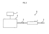
- a catalyst system 9 was formed which includes the exhaust gas purifying catalyst 1, a gasoline direct injection engine 5 of 2 L displacement which supplies an exhaust gas 3 to the exhaust gas purifying catalyst 1, and a computer 7 that controls the engine 5 to adjust a temperature (that is, a temperature of the exhaust gas purifying catalyst 1) and an A/F ratio of the exhaust gas 3.
- the exhaust gas purifying catalyst 1 provided in the catalyst system 9 is one of those manufactured by the Embodiments 1 to 9 and the Comparative Examples 1 to 3.
- the catalyst system 9 was driven for 800 hours.
- the rotary torque of the engine 5 was adjusted by the computer 7 thereby to set the internal temperature of the exhaust gas purifying catalyst 1 to 500°C.
- the composition of the exhaust gas 3 was controlled such that a lean state (A/F ratio: 18) basically appears and a spike-like rich state (A/F ratio: 14) having a duration of one second appears at intervals of thirty seconds, as shown in FIG. 3 .
- the oxidation treatment process is performed when the catalyst system 9 is driven such that the exhaust gas 3 is in a lean state.
- the reduction treatment process is performed when the catalyst system 9 is driven such that the exhaust gas 3 is in a rich state.
- average particle diameters of noble metal contained in the exhaust gas purifying catalyst 1 were measured.
- a TEM (transmission electron microscope) photo of the surface of the exhaust gas purifying catalyst 1 was taken using a TEM.
- Particle diameters of 300 noble metal particles in the TEM photo were respectively measured.
- the average particle diameter was calculated by averaging the particle diameters. Table 1 shows the results.
- the exhaust gas purifying catalyst 1 was attached to a direct injection engine of 2 L displacement to run the engine.
- the rotary torque of the engine was adjusted so that a gas temperature entering the exhaust gas purifying catalyst 1 is 200°C.
- a CO concentration C1 at the engine exit that is, upstream of the exhaust gas purifying catalyst 1
- a CO concentration C2 at the exit of the exhaust gas purifying catalyst 1 were respectively measured.
- the purification rate was calculated in accordance with Equation (1) below.
- the catalyst system 9 was constituted in the same manner as in a) of the Embodiment 10.
- a diesel engine turbine engine of common rail type
- 2.2 L displacement was used as the engine 5.
- the catalyst system 9 was driven for 1000 hours.
- the rotary torque of the engine 5 was adjusted by the computer 7 thereby to set the internal temperature of the exhaust gas purifying catalyst 1 to 300°C.
- the composition of the exhaust gas 3 was controlled such that the A/F ratio is basically 30 and that a state having a duration of twenty minutes and the A/F ratio of 18 appears at intervals of 10 hours, as shown in FIG. 4 .
- the oxidation treatment process is performed in the state having the A/F ratio of 30.
- the reduction treatment process is performed in the state having the A/F ratio of 18.
- the average particle diameters of noble metal in the exhaust gas purifying catalysts 1 according to the Embodiments 1 through 9 were very small.
- the average particle diameters of noble metal in the exhaust gas purifying catalysts 1 according to the Comparative Examples 1 through 3 were very large. This indicates that coagulation of noble metal particles is removed by the implementation of the recovery method so that the catalytic performance is recovered in the exhaust gas purifying catalysts 1 according to the Embodiments 1 through 9.
- the catalyst system 9 was constituted in the same manner as in a) of the Embodiment 10.
- a gasoline engine of 2.4 L displacement was used as the engine 5.
- the catalyst system 9 was driven for 50 hours.
- the rotary torque of the engine 5 was adjusted by the computer 7 thereby to set the internal temperature of the exhaust gas purifying catalyst 1 to 650°C.
- the composition of the exhaust gas 3 was controlled such that the center value of the A/F ratio is 14.6 and that the A/F ratio fluctuates in accordance with a sign curve having a frequency of 4 Hz and an amplitude of 0.2.
- the average particle diameters of noble metal in the exhaust gas purifying catalysts 1 according to the Embodiments 1 through 9 were very small.
- the average particle diameters of noble metal in the exhaust gas purifying catalysts 1 according to the Comparative Examples 1 through 3 were very large. This indicates that coagulation of noble metal particles is removed by the implementation of the recovery method so that the catalytic performance is recovered in the exhaust gas purifying catalysts 1 according to the Embodiments 1 through 9.
- the catalyst system 9 of the Embodiment 10 was driven for 800 hours.
- the driving conditions were basically the same as those in b)(ii) of the Embodiment 10.
- the composition of the exhaust gas 3 was kept lean (A/F ratio: 18) from beginning to end.
- the average particle diameters of noble metal in the recovery method according to the Reference Example 1 were larger than those in the recovery method according to the Embodiment 10. This indicates that noble metal particles are coagulated so that the catalytic performance is not recovered in the recovery method according to the Reference Example 1.
- the recovery method according to the Embodiment 10 is more effective in recovering the CO purification rates of the exhaust gas purifying catalysts than the recovery method according to the Reference Example 1.
- the catalyst system 9 of the Embodiment 11 was driven for 1000 hours.
- the driving conditions were basically the same as those in b)(ii) of the Embodiment 11.
- the composition of the exhaust gas 3 was kept such that the A/F ratio is 30 from beginning to end.
- the average particle diameters of noble metal in the recovery method according to the Reference Example 2 were larger than those in the recovery method according to the Embodiment 11. This indicates that noble metal particles are coagulated so that the catalytic performance is not recovered in the recovery method according to the Reference Example 2.
- the recovery method according to the Embodiment 11 is more effective in recovering the CO purification rates of the exhaust gas purifying catalysts than the recovery method according to the Reference Example 2.
- the average particle diameters of noble metal in the recovery method according to the Reference Example 3 were larger than those in the recovery method according to the Embodiment 12. This indicates that noble metal particles are coagulated so that the catalytic performance is not recovered in the recovery method according to the Reference Example 3.
- the recovery method according to the Embodiment 12 is more effective in recovering the CO purification rates of the exhaust gas purifying catalysts than the recovery method according to the Reference Example 1.
Landscapes
- Chemical & Material Sciences (AREA)
- Engineering & Computer Science (AREA)
- Chemical Kinetics & Catalysis (AREA)
- Organic Chemistry (AREA)
- Materials Engineering (AREA)
- Environmental & Geological Engineering (AREA)
- Biomedical Technology (AREA)
- Oil, Petroleum & Natural Gas (AREA)
- General Chemical & Material Sciences (AREA)
- Analytical Chemistry (AREA)
- Health & Medical Sciences (AREA)
- Combustion & Propulsion (AREA)
- Catalysts (AREA)
- Exhaust Gas Treatment By Means Of Catalyst (AREA)
Abstract
Description
- The present invention relates to an exhaust gas purifying catalyst that removes toxic substances contained in exhaust gas from an internal combustion engine of an automobile, a motorcycle, and others. The present invention also relates to a method for recovering the exhaust gas purifying catalyst, and a catalyst system.
- Conventionally, an exhaust gas purifying catalyst for use in an automobile or the like is known to include an oxide of alkali earth and rare earth supported by a noble metal such as Pt, Rh, Pd, and others.
- While the above exhaust gas purifying catalyst processes an exhaust gas, sintering sometimes occurs to the noble metal (especially Pt), which results in deterioration in catalytic activity. In such cases, an oxidation treatment process and a reduction treatment process are applied after processing of the exhaust gas. There is a proposal for a method for recovering the catalytic activity in that manner (see Patent Literature 1).
Patent Literature 1: Unexamined Japanese Patent Publication No.8-144748 - However, if the exhaust gas temperature in the oxidation treatment process is low when the above method for recovering the catalyst is performed, the noble metal remains coagulated. Moreover, different from the case of temporary deterioration, the catalytic performance has sometimes never been recovered. Therefore, there is a problem that the exhaust gas temperature must be strictly controlled when the oxidation treatment process is performed. Especially in a diesel engine, the exhaust gas temperature seldom becomes 600°C or above at normal driving in an urban area. It was difficult to apply the recovery method to a diesel vehicle.
- The present invention has been made in view of the above points. An object of the present invention is to provide an exhaust gas purifying catalyst that can recover the catalytic activity over a wide temperature range, a method of recovering an exhaust gas purifying catalyst, and a catalyst system for exhaust gas purification.
- (1) The invention according to
claim 1 provides an exhaust gas purifying catalyst which includes: an oxide A containing an oxide (A-1) containing an alkaline earth metal and/or a rare earth metal and an inorganic oxide (A-2); and a noble metal B supported by the oxide A. A weight ratio of the noble metal B to the oxide (A-1) containing an alkaline earth metal and/or a rare earth metal is from 1:10 to 1:300. - The exhaust gas purifying catalyst of the present invention has the aforementioned composition, especially, the weight ratio of the noble metal B to the oxide (A-1) is from 1:10 to 1:300 (preferably from 1:30 to 1:200). Thus, the exhaust gas purifying catalyst of the present invention can inhibit coagulation of noble metal particles and recover the catalytic performance even if the catalyst temperature at an oxidation treatment process is low (600°C or below, for example) when a recovery method is conducted. Accordingly, the exhaust gas purifying catalyst of the present invention can recover the catalytic activity by performing the oxidation treatment process by the exhaust gas having a temperature of 600°C or below.
- Generally, the exhaust gas temperature of an internal combustion engine is usually 600°C or below. That is, in the case of a gasoline vehicle, the frequency at which the exhaust gas temperature becomes 600°C or above at normal driving is very low in view of all the driving zones. Especially if there is high frequency of driving in a suburb, the exhaust gas temperature seldom reaches 600°C. Also, in the case of a diesel vehicle, the exhaust gas temperature is further low as compared to the case of a gasoline vehicle by 100°C. It is extremely rare that the exhaust gas temperature goes up to 600°C or above.
- As noted above, in the exhaust gas purifying catalyst of the present invention, the oxidation treatment process can be performed at low temperature. Accordingly, the oxidation treatment process can be performed by an exhaust gas having a temperature of 600°C or below to recover the catalytic activity. Therefore, there is no need for raising the catalyst temperature all the way up to 600°C or above upon performing the oxidation treatment process. There is an effect in that recovery is easy.
- Examples of the alkaline earth metal are Mg, Ca, Sr, Ba, and others. Examples of the rare earth metal are La, Ce, Pr, Nd, and others. The oxide (A-1) may be composed of one or both of the alkaline earth oxide and the rare earth metal oxide, or may further include another oxide other than the alkaline earth oxide and the rare earth metal oxide. The oxide (A-1) may be a compound having a crystal structure such as ABO3 (perovskite), AB2O4 (spinel), and others.
- Examples of the inorganic oxide (A-2) are other than the oxide (A-1), particularly one or more of those selected from a group consisting of Al2O3, SiO2, ZrO2, TiO2 and zeolite.
- Examples of the noble metal may be one or more of those selected from a group consisting of Pt, Pd, Rh and Ir. A preferable amount of the noble metal to be mixed is in a range from 0.1 to 3 g/L. Sufficient catalytic performance can be achieved if the amount of the noble metal to be mixed is 0.1 g/L or above. Increase in cost can be avoided if the amount of the noble metal to be mixed is 3 g/L or below.
- The weight ratio of the noble metal B to the oxide (A-1) is 1:10 to 1:300, more preferably 1:30 to 1:200. If the weight ratio of the noble metal B to the oxide (A-1) is 1:10 (preferably 1:30) or above, the noble metal B can hardly exist excessively. Thus, interaction between the oxide (A-1) and the noble metal B is strengthened. Effect in inhibiting coagulation of the noble metal B is enhanced. Also, if the weight ratio of the noble mental B to the oxide (A-1) is 1:300 (preferably 1:200) or below, effect in interaction between the oxide (A-1) and the noble metal B is large. Effect in inhibiting coagulation of the noble metal is enhanced.
- (2) The invention according to claim 2 provides the exhaust gas purifying catalyst as set forth in
claim 1 wherein the inorganic oxide (A-2) contains one or more of those selected from a group consisting of Al2O3, SiO2, ZrO2, TiO2 and zeolite. - The exhaust gas purifying catalyst of the present invention can recover the catalytic performance all the more effectively since the inorganic oxide (A-2) is one or more of the above.
- (3) The invention according to
claim 3 provides a method for recovering an exhaust gas purifying catalyst, which includes an oxidation treatment process that applies an oxidation treatment to the exhaust gas purifying catalyst as set forth in one ofclaims 1 to 3 by a lean state exhaust gas and a reduction treatment process that applies a reduction treatment to the exhaust gas purifying catalyst by a rich state exhaust gas. - According to the present invention, the catalytic performance of the exhaust gas purifying catalyst can be recovered.
- The lean state indicates a state of excessive air as compared to a stoichiometric state. For example, the A/F ratio is 14.6 or more in the case of a gasoline engine, and 14.5 or more in the case of a diesel engine. The rich state indicates a state of excessive fuel as compared to a stoichiometric state. For example, the A/F ratio is 14.6 or less in the case of a gasoline engine, and 14.5 or less in the case of a diesel engine.
- There is no limitation to a time period for which the oxidation treatment process and the reduction treatment process continue. Specifically, the time period for the reduction treatment process may be a spike-like processing time of about 0.1 sec, or may have a long duration of several hours. Patterns of the oxidation treatment process and the reduction treatment process may be as shown in
FIGS. 3 and4 , for example, that is, a section of the oxidation treatment process and a section of the reduction treatment process may be periodically switched over at certain timings so that the A/F ratios in each section may be constant. Or, as shown inFIG. 5 , the A/F ratio may be periodically changed little by little (for example, according to a sign curve) to form the oxidation treatment process and the reduction treatment process. - The percentage of the time period for which the oxidation treatment process continues in the overall time period for which the recovery method is conducted is preferably in a range of 60 to 80%. The percentage of the time period for which the reduction treatment process continues is preferably in a range of 10 to 30%.
- In the reduction treatment process, an exhaust gas under rich conditions by rich spike and S (sulphur) regeneration can be used, for example in the case of the exhaust gas purifying catalyst provided in a direct gasoline injection vehicle. In the case of the exhaust gas purifying catalyst provided in a diesel vehicle, an exhaust gas under rich conditions by post injection, HC addition in exhaust system, rich spike and S regeneration can be used.
- (4) The invention according to claim 4 provides the method for recovering an exhaust gas purifying catalyst as set forth in
claim 3 wherein a temperature of the exhaust gas purifying catalyst in the reduction treatment process is set from 200 to 900°C. - The recovery method of the present invention can increase a reducing action of noble metal and sufficiently recover the catalytic performance since the catalyst temperature in the reduction treatment process is set to 200°C or above (more preferably 500°C or above). Also, reducing effect is not decreased by excessive heat since the catalyst temperature in the reduction treatment process is set to 900°C or below (more preferably 600°C or below).
- (5) The invention according to
claim 5 provides the method for recovering an exhaust gas purifying catalyst as set forth inclaim 3 or 4 wherein a temperature of the exhaust gas purifying catalyst in the oxidation treatment process is set from 200 to 600°C. - The recovery method of the present invention can sufficiently recover the catalytic performance since the catalyst temperature in the oxidation treatment process is set to 200°C or above (more preferably 300°C or above). Also, the recovery method of the present invention can execute the oxidation treatment process by an exhaust gas having a temperature of 600°C or below and recover the catalytic activity since the catalyst temperature in the oxidation treatment process is 600°C or below (more preferably 500°C or below). Accordingly, there is no need of raising the catalyst temperature all the way up to 600°C or above when the oxidation treatment process is performed. There is effect in that recovery is easy.
- (6) The invention according to claim 6 provides a catalyst system for exhaust gas purification, including the exhaust gas purifying catalyst as set forth in
claim 1 or 2, a supply unit that supplies an exhaust gas to the exhaust gas purifying catalyst, and a control unit that can control the exhaust gas into either a lean or rich state. - In the catalyst system of the present invention, the exhaust gas may be controlled into a lean state by the control unit to perform the oxidation treatment process to the exhaust gas purifying catalyst. Also, the exhaust gas may be controlled into a rich state to perform the reduction treatment process to the exhaust gas purifying catalyst. That is, the catalyst system of the present invention can maintain the catalytic performance for a long term while recovering the catalytic performance of the exhaust gas purifying catalyst provided therein.
- An example of the supply unit may be an internal combustion engine for a gasoline engine and a diesel engine.
- An example of the control unit may be a computer that controls the state (rotary torque, for example) of the internal combustion engine.
- (7) The invention according to claim 7 provides the catalyst system for exhaust gas purification as set forth in claim 6, wherein the control unit controls a temperature of the exhaust gas purifying catalyst into 200 to 900°C when the exhaust gas is in the rich state.
- In the catalyst system of the present invention, the catalyst temperature is 200°C or above (more preferably 300°C or above) when the exhaust gas is in the rich state. Thus, a reducing action of noble metal is increased. The catalytic performance can be sufficiently recovered. Also, the catalyst temperature is 900°C or below (more preferably 600°C or below) when the exhaust gas is in the rich state. Thus, reducing effect is not decreased by excessive heat.
- (8) The invention according to claim 8 provides the catalyst system for exhaust gas purification as set forth in claim 6 or 7, wherein the control unit controls a temperature of the exhaust gas purifying catalyst to 200 to 600°C when the exhaust gas is in the lean state.
- In the catalyst system of the present invention, the catalyst temperature is 200°C or above (more preferably 300°C or above) when the exhaust gas is in the lean state. Thus, the catalytic performance can be sufficiently recovered. Also, the catalyst temperature is 600°C or below (more preferably 500°C or below) when the exhaust gas is in the lean state. Accordingly, the oxidation treatment is performed by an exhaust gas having a temperature of 600°C or below thereby to recover the catalytic activity. Thus, there is no need of raising the catalyst temperature all the way up to 600°C or above upon execution of the oxidation treatment. There is effect in that recovery is easy.
-
- [
FIG. 1 ] is a cross sectional view showing a structure of an exhaustgas purifying catalyst 1. - [
FIG. 2 ] is a diagram showing a structure of a catalyst system 9. - [
FIG. 3 ] is an explanatory diagram showing a transition of composition of an exhaust gas when a recovery method is conducted to the exhaustgas purifying catalyst 1. - [
FIG. 4 ] is an explanatory diagram showing a transition of composition of an exhaust gas when a recovery method is conducted to the exhaustgas purifying catalyst 1. - [
FIG. 5 ] is an explanatory diagram showing a transition of composition of an exhaust gas when a recovery method is conducted to the exhaustgas purifying catalyst 1. -
- 1
- exhaust gas purifying catalyst
- 3
- exhaust gas
- 5
- direct injection engine
- 7
- computer
- 9
- catalyst system
- 101
- ceramic honeycomb
- 103
- catalyst coating layer
- The present invention will be particularly explained by way of embodiments.
- An aluminum nitrate solution and a Nd nitrate solution were mixed. A 3% ammonia solution was added to the mixed solution little by little so that the pH of the mixed solution is adjusted to a value of 10. A mixture of Al-Nd was coprecipitated by hydrolysis reaction. After decantation is performed with ion-exchanged water, the precipitate and water were separated using a filter press. The precipitate was dried at 80°C for five hours to remove fluid, and then calcined at 650°C for an hour to obtain an Al-Nd inorganic oxide containing 20 wt% of Nd.
- 100 parts by weight of the above oxide, 20 parts by weight of alumina sol (AS200 manufactured by Nissan Chemical Industries, Ltd.) as a binder, a dinitrodiamino Pt acid, 150 parts by weight of ion-exchanged water were mixed and crushed for five hours by a ball mill to prepare a slurry.
- The above slurry was applied to coat an approximately 2L ceramic honeycomb 101 (400 cells/in2) having a diameter of 129 mm and a length of 150 mm, as shown in
FIG. 1 , to form acatalyst coating layer 103. After dried at 250°C, thecatalyst coating layer 103 was calcined at 500°C for an hour to finish an exhaustgas purifying catalyst 1. A supporting amount of Pt in thecatalyst coating layer 103 was 1.5 g/L. A coating amount of thecatalyst coating layer 103 was 150 g/L. A weight ratio of Pt to the Nd inorganic oxide in thecatalyst coating layer 103 is 1:13. - Based on the
Embodiment 1, an exhaust gas purifying catalyst was manufactured using Zr nitrate and Pr nitrate instead of aluminum nitrate and Nd nitrate. An amount of Pr in an inorganic oxide made from Zr nitrate and Pr nitrate was about 30 wt%. In the Embodiment 2, a weight ratio of Pt to the Zr-Pr inorganic oxide is 1:20. - Based on the
Embodiment 1, an exhaust gas purifying catalyst was manufactured using Mg nitrate instead of Nd nitrate. An amount of Mg in the inorganic oxide was about 50 wt%. In theEmbodiment 3, a weight ratio of Pt to the Mg inorganic oxide is 1:33. - Based on the
Embodiment 1, an exhaust gas purifying catalyst was manufactured using Mg nitrate and La nitrate instead of aluminum nitrate and Nd nitrate. An amount of La in an inorganic oxide made from Mg nitrate and La nitrate was about 10 wt%. In the Embodiment 4, a weight ratio of Pt to the Mg-La inorganic oxide is 1:90. - Based on the
Embodiment 1, an exhaust gas purifying catalyst was manufactured using a ternary mixing system of Pt nitrate, Pd nitrate and Rh nitrate as noble metal sources, instead of using Pt nitrate alone. Supporting amounts of Pt, Pd and Rh in the finished exhaust gas purifying catalyst were respectively 1.5 g/L, 0.3 g/L and 0.2 g/L. In theEmbodiment 5, a weight ratio of the total amount of noble metal (Pt, Pd and Rh) to the Al-Nd inorganic oxide is 1:10. - Based on the
Embodiment 1, an exhaust gas purifying catalyst was manufactured using Zr nitrate, Ce nitrate and Mg nitrate instead of aluminum nitrate and Nd nitrate. Relative proportions (mol%) among Zr, Ce and Mg in an inorganic oxide made from Zr nitrate, Ce nitrate and Mg nitrate were 40:40:20. A coating amount was 250 g/L. In the Embodiment 6, a weight ratio of Pt to the Zr-Ce-Mg inorganic oxide is 1:150. - 100 parts by powder weight of SiO2 powder (SSA 180 m2/g), 30 parts by weight of Mg oxide (SSA 45 m2/g), 30 parts by weight of alumina sol (AS200 manufactured by Nissan Chemical Industries, Ltd.), 5 parts by weight of acetic acid, and 100 parts by weight of ion-exchanged water were dispersed by an agitator. After addition of a dinitrodiamino Pt acid, the mixture was crushed for five hours by a ball mill to obtain a slurry. The slurry was applied to coat the
ceramic honeycomb 101 in the same manner as in theEmbodiment 1 to form acatalyst coating layer 103. Thereafter, thecatalyst coating layer 103 was dried and calcined to manufacture an exhaust gas purifying catalyst 1 (seeFIG. 1 ). A supporting amount of Pt in thecatalyst coating layer 103 was 1.5 g/L. A coating amount of thecatalyst coating layer 103 was 150 g/L. A weight ratio of Pt to Mg oxide in thecatalyst coating layer 103 is 1:20. - Based on the Embodiment 7, an exhaust gas purifying catalyst was manufactured using 70 parts by weight of zeolite (SiO2-Al2O3 ratio: 30, SSA 280 m2/g) instead of SiO2 powder and using 50 parts by weight of Nd oxide instead of Mg oxide. In the Embodiment 8, a weight ratio of Pt (1.5 g/L) to Nd oxide is 1:33.
- Based on the Embodiment 7, an exhaust gas purifying catalyst was manufactured using 100 parts by weight of Mg oxide (SSA 130 m2/g) added with 10 wt% of ZrO2 instead of SiO2 powder and Mg oxide. In the Embodiment 9, a weight ratio of Pt to Mg oxide is 1:250. A coating amount was 300 g/L. An amount of Pt was 1 g/L.
- 100 parts by weight of y alumina (SSA 190 m2/g), 10 parts by weight of boehmite alumina, 200 parts by weight of ion-exchanged water, and a dinitrodiamino Pt acid were mixed and crushed by a ball mill to prepare a slurry having an average particle diameter of 8 µm. The slurry was applied to coat the
honeycomb 101 in the same manner as in theEmbodiment 1 to form acatalyst coating layer 103. Thereafter, thecatalyst coating layer 103 was dried and calcined to manufacture an exhaust gas purifying catalyst. A supporting amount of Pt in thecatalyst coating layer 103 was 1.5 g/L. A coating amount of thecatalyst coating layer 103 was 150 g/L. - Based on the Embodiment 4, the supporting amount of Pt was made to 2 g/L. The coating amount was made to 100 g/L. In the Comparative Example 2, the weight ratio of noble metal (Pt) to the Mg-La oxide is 1:8.
- Based on the Embodiment 4, the supporting amount of Pt was made to 0.5 g/L. The coating amount was made to 200 g/L. In the Comparative Example 3, the weight ratio of noble metal (Pt) to the Mg-La oxide is 1:350.
- a) Catalyst system
- As shown in
FIG. 2 , a catalyst system 9 was formed which includes the exhaustgas purifying catalyst 1, a gasolinedirect injection engine 5 of 2 L displacement which supplies anexhaust gas 3 to the exhaustgas purifying catalyst 1, and a computer 7 that controls theengine 5 to adjust a temperature (that is, a temperature of the exhaust gas purifying catalyst 1) and an A/F ratio of theexhaust gas 3. - The exhaust
gas purifying catalyst 1 provided in the catalyst system 9 is one of those manufactured by theEmbodiments 1 to 9 and the Comparative Examples 1 to 3. - b) Durability of catalyst and recovery method
- (i) Implementation of durability test
- By means of an electric furnace, a 800°C, 10-hour hydrothermal durability test was conducted in an atmosphere containing 10 vol% of water vapor to the exhaust
gas purifying catalyst 1. - (ii) Recovery method
- Thereafter, the catalyst system 9 was driven for 800 hours. At the time, the rotary torque of the
engine 5 was adjusted by the computer 7 thereby to set the internal temperature of the exhaustgas purifying catalyst 1 to 500°C. Also, the composition of theexhaust gas 3 was controlled such that a lean state (A/F ratio: 18) basically appears and a spike-like rich state (A/F ratio: 14) having a duration of one second appears at intervals of thirty seconds, as shown inFIG. 3 . Here, the oxidation treatment process is performed when the catalyst system 9 is driven such that theexhaust gas 3 is in a lean state. The reduction treatment process is performed when the catalyst system 9 is driven such that theexhaust gas 3 is in a rich state. - c) Evaluation of exhaust
gas purifying catalyst 1 - (i) Measurement of average particle diameter of noble metal
- After the implementation of the recovery method in the above b), average particle diameters of noble metal contained in the exhaust
gas purifying catalyst 1 were measured. A TEM (transmission electron microscope) photo of the surface of the exhaustgas purifying catalyst 1 was taken using a TEM. Particle diameters of 300 noble metal particles in the TEM photo were respectively measured. The average particle diameter was calculated by averaging the particle diameters. Table 1 shows the results. -

- As shown in Table 1, the average particle diameters of noble metal in the exhaust gas purifying catalysts according to the
Embodiments 1 through 9 were very small. In contrast, the average particle diameters of noble metal in the exhaust gas purifying catalysts according to the Comparative Examples 1 through 3 were very large. These results show that coagulation of noble metal is removed by the implementation of the recovery method so that the catalytic performance is recovered in the exhaustgas purifying catalysts 1 according to theEmbodiments 1 through 9. - (ii) Evaluation of purification performance
- After the implementation of the recovery method of the above b), the exhaust
gas purifying catalyst 1 was attached to a direct injection engine of 2 L displacement to run the engine. The rotary torque of the engine was adjusted so that a gas temperature entering the exhaustgas purifying catalyst 1 is 200°C. By means of an exhaust gas analyzer manufactured by HORIBA, Ltd., a CO concentration C1 at the engine exit (that is, upstream of the exhaust gas purifying catalyst 1) and a CO concentration C2 at the exit of the exhaustgas purifying catalyst 1 were respectively measured. The purification rate was calculated in accordance with Equation (1) below. -

- Table 2 shows the measurement results.
-

- As shown in Table 2, CO purification rates of the exhaust
gas purifying catalysts 1 according to theEmbodiments 1 through 9 were much higher than those of the Comparative Examples 1 through 3. - a) Catalyst system
- In principle, the catalyst system 9 was constituted in the same manner as in a) of the Embodiment 10. In the Embodiment 11, a diesel engine (turbointercooled engine of common rail type) of 2.2 L displacement was used as the
engine 5. - b) Durability of catalyst and recovery method
- (i) Implementation of durability test
- A hydrothermal durability test was conducted in the same manner as in b)(i) of the Embodiment 10.
- (ii) Recovery method
- Thereafter, the catalyst system 9 was driven for 1000 hours. At the time, the rotary torque of the
engine 5 was adjusted by the computer 7 thereby to set the internal temperature of the exhaustgas purifying catalyst 1 to 300°C. Also, the composition of theexhaust gas 3 was controlled such that the A/F ratio is basically 30 and that a state having a duration of twenty minutes and the A/F ratio of 18 appears at intervals of 10 hours, as shown inFIG. 4 . Here, the oxidation treatment process is performed in the state having the A/F ratio of 30. The reduction treatment process is performed in the state having the A/F ratio of 18. - c) Evaluation of exhaust
gas purifying catalyst 1 - Average particle diameters of noble metal and purification rates were measured in the same manner as in c) of the Embodiment 10. The results are shown in the above Tables 1 and 2.
- As shown in Table 1, the average particle diameters of noble metal in the exhaust
gas purifying catalysts 1 according to theEmbodiments 1 through 9 were very small. In contrast, the average particle diameters of noble metal in the exhaustgas purifying catalysts 1 according to the Comparative Examples 1 through 3 were very large. This indicates that coagulation of noble metal particles is removed by the implementation of the recovery method so that the catalytic performance is recovered in the exhaustgas purifying catalysts 1 according to theEmbodiments 1 through 9. - Also as shown in Table 2, the CO purification rates of the exhaust
gas purifying catalysts 1 according to theEmbodiments 1 through 9 were much higher than those of the Comparative Examples 1 through 3. - a) Catalyst system
- In principle, the catalyst system 9 was constituted in the same manner as in a) of the Embodiment 10. In the Embodiment 12, a gasoline engine of 2.4 L displacement was used as the
engine 5. - b) Durability of catalyst and recovery method
- (i) Implementation of durability test
- The same hydrothermal durability test as in b)(i) of the Embodiment 10 was conducted.
- (ii) Recovery method
- Thereafter, the catalyst system 9 was driven for 50 hours. At the time, the rotary torque of the
engine 5 was adjusted by the computer 7 thereby to set the internal temperature of the exhaustgas purifying catalyst 1 to 650°C. Also, the composition of theexhaust gas 3 was controlled such that the center value of the A/F ratio is 14.6 and that the A/F ratio fluctuates in accordance with a sign curve having a frequency of 4 Hz and an amplitude of 0.2. - c) Evaluation of exhaust
gas purifying catalyst 1 - Average particle diameters of noble metal and purification rates were measured in the same manner as in c) of the Embodiment 10. The results are shown in the above Tables 1 and 2.
- As shown in Table 1, the average particle diameters of noble metal in the exhaust
gas purifying catalysts 1 according to theEmbodiments 1 through 9 were very small. In contrast, the average particle diameters of noble metal in the exhaustgas purifying catalysts 1 according to the Comparative Examples 1 through 3 were very large. This indicates that coagulation of noble metal particles is removed by the implementation of the recovery method so that the catalytic performance is recovered in the exhaustgas purifying catalysts 1 according to theEmbodiments 1 through 9. - Also as shown in Table 2, the CO purification rates of the exhaust
gas purifying catalysts 1 according to theEmbodiments 1 through 9 were much higher than those of the Comparative Examples 1 through 3. - After the same hydrothermal duration test as in b)(i) of the Embodiment 10 was conducted to the catalyst system 9 of the Embodiment 10, the catalyst system 9 was driven for 800 hours. The driving conditions were basically the same as those in b)(ii) of the Embodiment 10. The composition of the
exhaust gas 3 was kept lean (A/F ratio: 18) from beginning to end. - Thereafter, in the same manner as in c) of the Embodiment 10, average particle diameters of noble metal and purification rates were measured. The results were shown in the above Tables 1 and 2.
- As shown in Table 1, the average particle diameters of noble metal in the recovery method according to the Reference Example 1 were larger than those in the recovery method according to the Embodiment 10. This indicates that noble metal particles are coagulated so that the catalytic performance is not recovered in the recovery method according to the Reference Example 1.
- Also as shown in Table 2, the recovery method according to the Embodiment 10 is more effective in recovering the CO purification rates of the exhaust gas purifying catalysts than the recovery method according to the Reference Example 1.
- After the same hydrothermal duration test as in b)(i) of the Embodiment 10 was conducted to the catalyst system 9 of the Embodiment 11, the catalyst system 9 was driven for 1000 hours. The driving conditions were basically the same as those in b)(ii) of the Embodiment 11. The composition of the
exhaust gas 3 was kept such that the A/F ratio is 30 from beginning to end. - Thereafter, in the same manner as in c) of the Embodiment 10, average particle diameters of noble metal and purification rates were measured. The results were shown in the above Tables 1 and 2.
- As shown in Table 1, the average particle diameters of noble metal in the recovery method according to the Reference Example 2 were larger than those in the recovery method according to the Embodiment 11. This indicates that noble metal particles are coagulated so that the catalytic performance is not recovered in the recovery method according to the Reference Example 2.
- Also as shown in Table 2, the recovery method according to the Embodiment 11 is more effective in recovering the CO purification rates of the exhaust gas purifying catalysts than the recovery method according to the Reference Example 2.
- After the same hydrothermal duration test as in b)(i) of the Embodiment 10 was conducted to the catalyst system 9 of the Embodiment 12, the catalyst system 9 was driven for 50 hours. The driving conditions were basically the same as those in b)(ii) of the Embodiment 12. The composition of the
exhaust gas 3 was kept lean (A/F ratio: 23) from beginning to end. - Thereafter, in the same manner as in c) of the Embodiment 10, average particle diameters of noble metal and purification rates were measured. The results were shown in the above Tables 1 and 2.
- As shown in Table 1, the average particle diameters of noble metal in the recovery method according to the Reference Example 3 were larger than those in the recovery method according to the Embodiment 12. This indicates that noble metal particles are coagulated so that the catalytic performance is not recovered in the recovery method according to the Reference Example 3.
- Also as shown in Table 2, the recovery method according to the Embodiment 12 is more effective in recovering the CO purification rates of the exhaust gas purifying catalysts than the recovery method according to the Reference Example 1.
- It is to be understood that the present invention should not be limited to the above described embodiments, but may be practiced in various forms within the scope not departing from the present invention.
Claims (8)
- An exhaust gas purifying catalyst comprising:an oxide A containing an oxide (A-1) containing an alkaline earth metal and/or a rare earth metal and an inorganic oxide (A-2); anda noble metal B supported by the oxide A,wherein a weight ratio of the noble metal B to the oxide (A-1) containing an alkaline earth metal and/or a rare earth metal is from 1:10 to 1:300.
- The exhaust gas purifying catalyst according to claim 1,
wherein the inorganic oxide (A-2) contains one or more of those selected from a group consisting of Al2O3, SiO2, ZrO2, TiO2 and zeolite. - A method for recovering an exhaust gas purifying catalyst comprising:an oxidation treatment process that applies an oxidation treatment to the exhaust gas purifying catalyst according to one of claims 1 to 3 in a lean exhaust gas; anda reduction treatment process that applies a reduction treatment to the exhaust gas purifying catalyst in a rich exhaust gas.
- The method for recovering an exhaust gas purifying catalyst according to claim 3,
wherein a temperature of the exhaust gas purifying catalyst in the reduction treatment process is set from 200 to 900°C. - The method for recovering an exhaust gas purifying catalyst according to claim 3 or 4,
wherein a temperature of the exhaust gas purifying catalyst in the oxidation treatment process is set from 200 to 600°C. - A catalyst system for exhaust gas purification comprising:the exhaust gas purifying catalyst according to claim 1 or 2;a supply unit that supplies an exhaust gas to the exhaust gas purifying catalyst; anda control unit that can control the exhaust gas into either a lean or rich state.
- The catalyst system for exhaust gas purification according to claim 6,
wherein the control unit controls a temperature of the exhaust gas purifying catalyst into 200 to 900°C when the exhaust gas is in the rich state. - The catalyst system for exhaust gas purification according to claim 6 or 7,
wherein the control unit controls a temperature of the exhaust gas purifying catalyst into 200 to 600°C when the exhaust gas is in the lean state.
Applications Claiming Priority (2)
| Application Number | Priority Date | Filing Date | Title |
|---|---|---|---|
| JP2006117958A JP5582671B2 (en) | 2006-04-21 | 2006-04-21 | Exhaust gas purification catalyst, exhaust gas purification catalyst recovery method, and exhaust gas purification catalyst system |
| PCT/JP2007/058638 WO2007123205A1 (en) | 2006-04-21 | 2007-04-20 | Exhaust gas purifying catalyst, method for recovering exhaust gas purifying catalyst, and catalyst system for exhaust gas purification |
Publications (2)
| Publication Number | Publication Date |
|---|---|
| EP2011570A1 true EP2011570A1 (en) | 2009-01-07 |
| EP2011570A4 EP2011570A4 (en) | 2012-07-25 |
Family
ID=38625105
Family Applications (1)
| Application Number | Title | Priority Date | Filing Date |
|---|---|---|---|
| EP07742073A Withdrawn EP2011570A4 (en) | 2006-04-21 | 2007-04-20 | Exhaust gas purifying catalyst, method for recovering exhaust gas purifying catalyst, and catalyst system for exhaust gas purification |
Country Status (6)
| Country | Link |
|---|---|
| US (1) | US8071498B2 (en) |
| EP (1) | EP2011570A4 (en) |
| JP (1) | JP5582671B2 (en) |
| KR (1) | KR100995458B1 (en) |
| CN (2) | CN102198370B (en) |
| WO (1) | WO2007123205A1 (en) |
Cited By (1)
| Publication number | Priority date | Publication date | Assignee | Title |
|---|---|---|---|---|
| EP2368849B2 (en) † | 2008-12-22 | 2025-03-19 | Tosoh Corporation | Chabazite-type zeolite and process for producing the same |
Families Citing this family (12)
| Publication number | Priority date | Publication date | Assignee | Title |
|---|---|---|---|---|
| CN103118777B (en) | 2010-05-24 | 2016-06-29 | 希路瑞亚技术公司 | nanowire catalyst |
| CN103764276B (en) | 2011-05-24 | 2017-11-07 | 希路瑞亚技术公司 | Catalysts for the Oxidative Coupling of Methane |
| US20130158322A1 (en) | 2011-11-29 | 2013-06-20 | Siluria Technologies, Inc. | Polymer templated nanowire catalysts |
| US9446397B2 (en) | 2012-02-03 | 2016-09-20 | Siluria Technologies, Inc. | Method for isolation of nanomaterials |
| CA2874043C (en) | 2012-05-24 | 2021-09-14 | Siluria Technologies, Inc. | Catalytic forms and formulations |
| WO2014143880A1 (en) | 2013-03-15 | 2014-09-18 | Siluria Technologies, Inc. | Catalysts for petrochemical catalysis |
| JP6618924B2 (en) | 2013-12-23 | 2019-12-11 | ローディア オペレーションズ | Inorganic oxide material |
| WO2015168601A2 (en) | 2014-05-02 | 2015-11-05 | Siluria Technologies, Inc. | Heterogeneous catalysts |
| HUE054014T2 (en) | 2014-09-17 | 2021-08-30 | Lummus Technology Inc | Catalysts for oxidative coupling of methane and oxidative dehydrogenation of ethane |
| EP3429747A2 (en) | 2016-03-16 | 2019-01-23 | Siluria Technologies, Inc. | Catalysts and methods for natural gas processes |
| BR112018072443B1 (en) * | 2016-05-05 | 2022-05-10 | Johnson Matthey Public Limited Company | Nox adsorbent catalyst for treating emissions from a lean-burning engine, emission treatment system for treating a flux of a combustion exhaust gas, and, method for treating an exhaust gas of an internal combustion engine |
| CA3127339A1 (en) | 2019-01-30 | 2020-08-06 | Lummus Technology Llc | Catalysts for oxidative coupling of methane |
Family Cites Families (31)
| Publication number | Priority date | Publication date | Assignee | Title |
|---|---|---|---|---|
| JPH08144748A (en) | 1994-11-22 | 1996-06-04 | Nissan Motor Co Ltd | Exhaust gas purification device for internal combustion engine |
| US6165429A (en) * | 1997-01-10 | 2000-12-26 | Toyota Jidosha Kabushiki Kaisha | Exhaust gas purifying catalyst and exhaust gas purifying method |
| EP0892159A3 (en) * | 1997-07-17 | 2000-04-26 | Hitachi, Ltd. | Exhaust gas cleaning apparatus and method for internal combustion engine |
| JP3688871B2 (en) * | 1997-11-20 | 2005-08-31 | ダイハツ工業株式会社 | Exhaust gas purification catalyst |
| JP3741303B2 (en) * | 1997-12-08 | 2006-02-01 | トヨタ自動車株式会社 | Exhaust gas purification catalyst |
| JPH11221467A (en) * | 1998-02-05 | 1999-08-17 | Toyota Motor Corp | Exhaust gas purification catalyst |
| DE19813655C2 (en) * | 1998-03-27 | 2000-04-27 | Degussa | Storage material for sulfur oxides, process for its production and use |
| KR19990083414A (en) * | 1998-04-27 | 1999-11-25 | 카와무라 히데오 | A Purifying system for exhaust gas and controlling method thereof |
| JP4309978B2 (en) * | 1998-08-25 | 2009-08-05 | 株式会社日立製作所 | Exhaust gas purification method, exhaust gas purification device, and exhaust gas purification catalyst |
| JP3673816B2 (en) * | 1999-03-15 | 2005-07-20 | 株式会社豊田中央研究所 | Exhaust gas purification catalyst and exhaust gas purification method |
| JP2001000840A (en) * | 1999-06-21 | 2001-01-09 | Toyota Central Res & Dev Lab Inc | Exhaust gas purification equipment |
| JP3724708B2 (en) * | 1999-11-26 | 2005-12-07 | 日産自動車株式会社 | Exhaust gas purification catalyst |
| JP4590733B2 (en) * | 2000-02-22 | 2010-12-01 | マツダ株式会社 | Exhaust gas purification catalyst and exhaust gas purification method using the catalyst |
| US6468484B1 (en) * | 2000-06-29 | 2002-10-22 | Delphi Technologies, Inc. | NO2 abatement composition with enhanced sulfur resistance |
| JP2002115534A (en) * | 2000-10-12 | 2002-04-19 | Hitachi Ltd | Exhaust gas purification device for internal combustion engine |
| JP4144174B2 (en) * | 2000-10-25 | 2008-09-03 | トヨタ自動車株式会社 | Exhaust gas purification device |
| JP2002133170A (en) * | 2000-10-26 | 2002-05-10 | Sony Corp | Idea investment device, idea operation device using the same, and their methods |
| JP2002166170A (en) * | 2000-11-29 | 2002-06-11 | Nissan Motor Co Ltd | Exhaust gas purification catalyst and method for producing the same |
| JP2002239383A (en) * | 2001-02-16 | 2002-08-27 | Toyota Central Res & Dev Lab Inc | NOx storage reduction catalyst and method of using the same |
| JP4019351B2 (en) * | 2001-03-12 | 2007-12-12 | 日産自動車株式会社 | NOx purification catalyst and NOx purification system |
| US6866834B2 (en) * | 2001-03-12 | 2005-03-15 | Nissan Motor Co., Ltd. | NOx reduction catalyst and NOx reduction system |
| JP3985054B2 (en) * | 2002-02-22 | 2007-10-03 | マツダ株式会社 | Exhaust gas purification catalyst |
| JP4254208B2 (en) * | 2002-11-20 | 2009-04-15 | 株式会社日立製作所 | Internal combustion engine exhaust gas purification device, purification method and catalyst |
| JP2004216223A (en) * | 2003-01-10 | 2004-08-05 | Toyota Central Res & Dev Lab Inc | NOx storage reduction catalyst |
| JP2004216224A (en) * | 2003-01-10 | 2004-08-05 | Toyota Central Res & Dev Lab Inc | NOx storage reduction catalyst |
| JP3795871B2 (en) * | 2003-03-20 | 2006-07-12 | 株式会社キャタラー | Exhaust gas purification catalyst system |
| JP2006043637A (en) * | 2004-08-06 | 2006-02-16 | Toyota Motor Corp | Exhaust gas purification catalyst |
| JP4556587B2 (en) * | 2004-09-22 | 2010-10-06 | マツダ株式会社 | Exhaust gas purification device |
| CN1724154A (en) | 2005-06-10 | 2006-01-25 | 陈昭萍 | Catalyst for purifying exhaust gas of natural gas engine and preparation method thereof |
| JP4833605B2 (en) * | 2005-07-21 | 2011-12-07 | 株式会社キャタラー | Exhaust gas purification catalyst |
| JP4435750B2 (en) * | 2006-03-30 | 2010-03-24 | 株式会社キャタラー | Exhaust gas purification catalyst and method for producing the same |
-
2006
- 2006-04-21 JP JP2006117958A patent/JP5582671B2/en not_active Expired - Fee Related
-
2007
- 2007-04-20 WO PCT/JP2007/058638 patent/WO2007123205A1/en not_active Ceased
- 2007-04-20 EP EP07742073A patent/EP2011570A4/en not_active Withdrawn
- 2007-04-20 KR KR1020087023989A patent/KR100995458B1/en not_active Expired - Fee Related
- 2007-04-20 CN CN2011101220522A patent/CN102198370B/en not_active Expired - Fee Related
- 2007-04-20 CN CN2007800127049A patent/CN101421037B/en not_active Expired - Fee Related
- 2007-04-20 US US12/297,660 patent/US8071498B2/en not_active Expired - Fee Related
Cited By (1)
| Publication number | Priority date | Publication date | Assignee | Title |
|---|---|---|---|---|
| EP2368849B2 (en) † | 2008-12-22 | 2025-03-19 | Tosoh Corporation | Chabazite-type zeolite and process for producing the same |
Also Published As
| Publication number | Publication date |
|---|---|
| CN102198370B (en) | 2013-08-28 |
| JP5582671B2 (en) | 2014-09-03 |
| CN101421037B (en) | 2012-06-06 |
| JP2007289812A (en) | 2007-11-08 |
| US20090099005A1 (en) | 2009-04-16 |
| KR20090003295A (en) | 2009-01-09 |
| CN101421037A (en) | 2009-04-29 |
| EP2011570A4 (en) | 2012-07-25 |
| US8071498B2 (en) | 2011-12-06 |
| KR100995458B1 (en) | 2010-11-18 |
| WO2007123205A1 (en) | 2007-11-01 |
| CN102198370A (en) | 2011-09-28 |
Similar Documents
| Publication | Publication Date | Title |
|---|---|---|
| EP2011570A1 (en) | Exhaust gas purifying catalyst, method for recovering exhaust gas purifying catalyst, and catalyst system for exhaust gas purification | |
| KR101688850B1 (en) | Nitrogen oxide storage catalytic converter for use in a motor vehicle in a position near the engine | |
| RU2736939C2 (en) | Catalysts for removal of nitrous oxide for exhaust systems | |
| EP2025401B1 (en) | NOx REDUCTION CATALYST, NOx REDUCTION CATALYST SYSTEM, AND METHOD FOR REDUCING NOx | |
| CN101528326B (en) | Vanadium-free catalyst for selective catalytic reduction and its preparation method | |
| RU2744472C1 (en) | Oxygen-accumulating and producing material, catalyst, exhaust gas purification system and method for purifying same | |
| JPH11322339A (en) | Cerium-zirconium-based composite oxide, method for producing the same, and catalyst material for purifying exhaust gas | |
| EP1570903B1 (en) | EXHAUST GAS PURIFYING CATALYST, METHOD FOR PURIFYING EXHAUST GAS and use of catalyst component for suppressing oxidation of sulphur dioxide in exhaust gases | |
| EP2029261B1 (en) | Catalyst for purification of exhaust gas | |
| KR101208888B1 (en) | Composition based on zirconium oxide, yttrium oxide and tungsten oxide, method of preparation and use as catalyst or catalyst support | |
| WO2007122917A1 (en) | Exhaust gas purifying catalyst and method for producing same | |
| JP4794834B2 (en) | Exhaust gas purification catalyst | |
| EP3815780B1 (en) | Diesel oxidation catalyst | |
| ZA200506234B (en) | Catalyst for purifying exhaust gases and process for producing the same | |
| JP3766568B2 (en) | Exhaust gas purification catalyst and exhaust gas purification method | |
| JP5030573B2 (en) | Composite oxide powder and method for producing the same |
Legal Events
| Date | Code | Title | Description |
|---|---|---|---|
| PUAI | Public reference made under article 153(3) epc to a published international application that has entered the european phase |
Free format text: ORIGINAL CODE: 0009012 |
|
| 17P | Request for examination filed |
Effective date: 20080910 |
|
| AK | Designated contracting states |
Kind code of ref document: A1 Designated state(s): AT BE BG CH CY CZ DE DK EE ES FI FR GB GR HU IE IS IT LI LT LU LV MC MT NL PL PT RO SE SI SK TR |
|
| AX | Request for extension of the european patent |
Extension state: AL BA HR MK RS |
|
| DAX | Request for extension of the european patent (deleted) | ||
| RBV | Designated contracting states (corrected) |
Designated state(s): DE FR GB IT |
|
| A4 | Supplementary search report drawn up and despatched |
Effective date: 20120626 |
|
| RIC1 | Information provided on ipc code assigned before grant |
Ipc: B01D 53/94 20060101ALI20120620BHEP Ipc: B01J 23/63 20060101AFI20120620BHEP Ipc: B01J 23/96 20060101ALI20120620BHEP Ipc: B01D 53/86 20060101ALI20120620BHEP Ipc: B01J 38/04 20060101ALI20120620BHEP Ipc: B01J 23/42 20060101ALI20120620BHEP |
|
| 17Q | First examination report despatched |
Effective date: 20131204 |
|
| STAA | Information on the status of an ep patent application or granted ep patent |
Free format text: STATUS: THE APPLICATION IS DEEMED TO BE WITHDRAWN |
|
| 18D | Application deemed to be withdrawn |
Effective date: 20180807 |