JP4833605B2 - Exhaust gas purification catalyst - Google Patents
Exhaust gas purification catalyst Download PDFInfo
- Publication number
- JP4833605B2 JP4833605B2 JP2005211494A JP2005211494A JP4833605B2 JP 4833605 B2 JP4833605 B2 JP 4833605B2 JP 2005211494 A JP2005211494 A JP 2005211494A JP 2005211494 A JP2005211494 A JP 2005211494A JP 4833605 B2 JP4833605 B2 JP 4833605B2
- Authority
- JP
- Japan
- Prior art keywords
- exhaust gas
- upstream
- downstream
- catalyst
- slurry
- Prior art date
- Legal status (The legal status is an assumption and is not a legal conclusion. Google has not performed a legal analysis and makes no representation as to the accuracy of the status listed.)
- Active
Links
- 239000003054 catalyst Substances 0.000 title claims description 140
- 238000000746 purification Methods 0.000 title claims description 23
- 239000010410 layer Substances 0.000 claims description 162
- 238000011144 upstream manufacturing Methods 0.000 claims description 111
- 239000002131 composite material Substances 0.000 claims description 64
- 229910000510 noble metal Inorganic materials 0.000 claims description 32
- 239000000203 mixture Substances 0.000 claims description 29
- 229910052809 inorganic oxide Inorganic materials 0.000 claims description 18
- 239000011248 coating agent Substances 0.000 claims description 12
- 238000000576 coating method Methods 0.000 claims description 12
- 239000000758 substrate Substances 0.000 claims description 12
- RCFVMJKOEJFGTM-UHFFFAOYSA-N cerium zirconium Chemical compound [Zr].[Ce] RCFVMJKOEJFGTM-UHFFFAOYSA-N 0.000 claims description 8
- 239000011247 coating layer Substances 0.000 claims description 6
- 239000002002 slurry Substances 0.000 description 103
- 239000010948 rhodium Substances 0.000 description 83
- 239000007789 gas Substances 0.000 description 71
- KDLHZDBZIXYQEI-UHFFFAOYSA-N Palladium Chemical compound [Pd] KDLHZDBZIXYQEI-UHFFFAOYSA-N 0.000 description 42
- PNEYBMLMFCGWSK-UHFFFAOYSA-N aluminium oxide Inorganic materials [O-2].[O-2].[O-2].[Al+3].[Al+3] PNEYBMLMFCGWSK-UHFFFAOYSA-N 0.000 description 39
- GRYLNZFGIOXLOG-UHFFFAOYSA-N Nitric acid Chemical compound O[N+]([O-])=O GRYLNZFGIOXLOG-UHFFFAOYSA-N 0.000 description 26
- 229910017604 nitric acid Inorganic materials 0.000 description 26
- 239000000463 material Substances 0.000 description 25
- 230000000052 comparative effect Effects 0.000 description 24
- 210000004027 cell Anatomy 0.000 description 22
- XLYOFNOQVPJJNP-UHFFFAOYSA-N water Substances O XLYOFNOQVPJJNP-UHFFFAOYSA-N 0.000 description 21
- BASFCYQUMIYNBI-UHFFFAOYSA-N platinum Chemical compound [Pt] BASFCYQUMIYNBI-UHFFFAOYSA-N 0.000 description 17
- 238000004519 manufacturing process Methods 0.000 description 12
- 238000000034 method Methods 0.000 description 10
- 238000001035 drying Methods 0.000 description 9
- 238000010304 firing Methods 0.000 description 9
- TZCXTZWJZNENPQ-UHFFFAOYSA-L barium sulfate Chemical compound [Ba+2].[O-]S([O-])(=O)=O TZCXTZWJZNENPQ-UHFFFAOYSA-L 0.000 description 6
- 229910052697 platinum Inorganic materials 0.000 description 6
- 229910052703 rhodium Inorganic materials 0.000 description 6
- 229910052788 barium Inorganic materials 0.000 description 5
- 229910052763 palladium Inorganic materials 0.000 description 5
- 229910052684 Cerium Inorganic materials 0.000 description 4
- MCMNRKCIXSYSNV-UHFFFAOYSA-N ZrO2 Inorganic materials O=[Zr]=O MCMNRKCIXSYSNV-UHFFFAOYSA-N 0.000 description 4
- 239000000919 ceramic Substances 0.000 description 4
- GWXLDORMOJMVQZ-UHFFFAOYSA-N cerium Chemical compound [Ce] GWXLDORMOJMVQZ-UHFFFAOYSA-N 0.000 description 4
- 229910052746 lanthanum Inorganic materials 0.000 description 4
- 229910052726 zirconium Inorganic materials 0.000 description 4
- 229910017569 La2(CO3)3 Inorganic materials 0.000 description 3
- 229910002651 NO3 Inorganic materials 0.000 description 3
- NHNBFGGVMKEFGY-UHFFFAOYSA-N Nitrate Chemical compound [O-][N+]([O-])=O NHNBFGGVMKEFGY-UHFFFAOYSA-N 0.000 description 3
- NZPIUJUFIFZSPW-UHFFFAOYSA-H lanthanum carbonate Chemical compound [La+3].[La+3].[O-]C([O-])=O.[O-]C([O-])=O.[O-]C([O-])=O NZPIUJUFIFZSPW-UHFFFAOYSA-H 0.000 description 3
- 229960001633 lanthanum carbonate Drugs 0.000 description 3
- 238000002156 mixing Methods 0.000 description 3
- MHOVAHRLVXNVSD-UHFFFAOYSA-N rhodium atom Chemical compound [Rh] MHOVAHRLVXNVSD-UHFFFAOYSA-N 0.000 description 3
- VYPSYNLAJGMNEJ-UHFFFAOYSA-N Silicium dioxide Chemical compound O=[Si]=O VYPSYNLAJGMNEJ-UHFFFAOYSA-N 0.000 description 2
- GWEVSGVZZGPLCZ-UHFFFAOYSA-N Titan oxide Chemical compound O=[Ti]=O GWEVSGVZZGPLCZ-UHFFFAOYSA-N 0.000 description 2
- QCWXUUIWCKQGHC-UHFFFAOYSA-N Zirconium Chemical compound [Zr] QCWXUUIWCKQGHC-UHFFFAOYSA-N 0.000 description 2
- 230000015572 biosynthetic process Effects 0.000 description 2
- 229910000420 cerium oxide Inorganic materials 0.000 description 2
- RVTZCBVAJQQJTK-UHFFFAOYSA-N oxygen(2-);zirconium(4+) Chemical compound [O-2].[O-2].[Zr+4] RVTZCBVAJQQJTK-UHFFFAOYSA-N 0.000 description 2
- 239000010970 precious metal Substances 0.000 description 2
- 229910001928 zirconium oxide Inorganic materials 0.000 description 2
- 229910052779 Neodymium Inorganic materials 0.000 description 1
- 229910052777 Praseodymium Inorganic materials 0.000 description 1
- QVGXLLKOCUKJST-UHFFFAOYSA-N atomic oxygen Chemical compound [O] QVGXLLKOCUKJST-UHFFFAOYSA-N 0.000 description 1
- DSAJWYNOEDNPEQ-UHFFFAOYSA-N barium atom Chemical compound [Ba] DSAJWYNOEDNPEQ-UHFFFAOYSA-N 0.000 description 1
- 230000003197 catalytic effect Effects 0.000 description 1
- 238000002485 combustion reaction Methods 0.000 description 1
- 150000001875 compounds Chemical class 0.000 description 1
- 229910052878 cordierite Inorganic materials 0.000 description 1
- JSKIRARMQDRGJZ-UHFFFAOYSA-N dimagnesium dioxido-bis[(1-oxido-3-oxo-2,4,6,8,9-pentaoxa-1,3-disila-5,7-dialuminabicyclo[3.3.1]nonan-7-yl)oxy]silane Chemical compound [Mg++].[Mg++].[O-][Si]([O-])(O[Al]1O[Al]2O[Si](=O)O[Si]([O-])(O1)O2)O[Al]1O[Al]2O[Si](=O)O[Si]([O-])(O1)O2 JSKIRARMQDRGJZ-UHFFFAOYSA-N 0.000 description 1
- 238000006073 displacement reaction Methods 0.000 description 1
- 238000002474 experimental method Methods 0.000 description 1
- FZLIPJUXYLNCLC-UHFFFAOYSA-N lanthanum atom Chemical compound [La] FZLIPJUXYLNCLC-UHFFFAOYSA-N 0.000 description 1
- 229910052751 metal Inorganic materials 0.000 description 1
- 239000002184 metal Substances 0.000 description 1
- 239000001301 oxygen Substances 0.000 description 1
- 229910052760 oxygen Inorganic materials 0.000 description 1
- 239000000377 silicon dioxide Substances 0.000 description 1
- 239000007787 solid Substances 0.000 description 1
- 229910001220 stainless steel Inorganic materials 0.000 description 1
- 238000010998 test method Methods 0.000 description 1
- 239000002912 waste gas Substances 0.000 description 1
- 229910052727 yttrium Inorganic materials 0.000 description 1
Images


Classifications
-
- B01J35/19—
-
- B—PERFORMING OPERATIONS; TRANSPORTING
- B01—PHYSICAL OR CHEMICAL PROCESSES OR APPARATUS IN GENERAL
- B01D—SEPARATION
- B01D53/00—Separation of gases or vapours; Recovering vapours of volatile solvents from gases; Chemical or biological purification of waste gases, e.g. engine exhaust gases, smoke, fumes, flue gases, aerosols
- B01D53/34—Chemical or biological purification of waste gases
- B01D53/92—Chemical or biological purification of waste gases of engine exhaust gases
- B01D53/94—Chemical or biological purification of waste gases of engine exhaust gases by catalytic processes
- B01D53/9445—Simultaneously removing carbon monoxide, hydrocarbons or nitrogen oxides making use of three-way catalysts [TWC] or four-way-catalysts [FWC]
- B01D53/945—Simultaneously removing carbon monoxide, hydrocarbons or nitrogen oxides making use of three-way catalysts [TWC] or four-way-catalysts [FWC] characterised by a specific catalyst
-
- B—PERFORMING OPERATIONS; TRANSPORTING
- B01—PHYSICAL OR CHEMICAL PROCESSES OR APPARATUS IN GENERAL
- B01J—CHEMICAL OR PHYSICAL PROCESSES, e.g. CATALYSIS OR COLLOID CHEMISTRY; THEIR RELEVANT APPARATUS
- B01J23/00—Catalysts comprising metals or metal oxides or hydroxides, not provided for in group B01J21/00
- B01J23/38—Catalysts comprising metals or metal oxides or hydroxides, not provided for in group B01J21/00 of noble metals
- B01J23/54—Catalysts comprising metals or metal oxides or hydroxides, not provided for in group B01J21/00 of noble metals combined with metals, oxides or hydroxides provided for in groups B01J23/02 - B01J23/36
- B01J23/56—Platinum group metals
- B01J23/63—Platinum group metals with rare earths or actinides
-
- B—PERFORMING OPERATIONS; TRANSPORTING
- B01—PHYSICAL OR CHEMICAL PROCESSES OR APPARATUS IN GENERAL
- B01J—CHEMICAL OR PHYSICAL PROCESSES, e.g. CATALYSIS OR COLLOID CHEMISTRY; THEIR RELEVANT APPARATUS
- B01J37/00—Processes, in general, for preparing catalysts; Processes, in general, for activation of catalysts
- B01J37/02—Impregnation, coating or precipitation
- B01J37/024—Multiple impregnation or coating
- B01J37/0244—Coatings comprising several layers
-
- F—MECHANICAL ENGINEERING; LIGHTING; HEATING; WEAPONS; BLASTING
- F01—MACHINES OR ENGINES IN GENERAL; ENGINE PLANTS IN GENERAL; STEAM ENGINES
- F01N—GAS-FLOW SILENCERS OR EXHAUST APPARATUS FOR MACHINES OR ENGINES IN GENERAL; GAS-FLOW SILENCERS OR EXHAUST APPARATUS FOR INTERNAL COMBUSTION ENGINES
- F01N3/00—Exhaust or silencing apparatus having means for purifying, rendering innocuous, or otherwise treating exhaust
- F01N3/08—Exhaust or silencing apparatus having means for purifying, rendering innocuous, or otherwise treating exhaust for rendering innocuous
- F01N3/10—Exhaust or silencing apparatus having means for purifying, rendering innocuous, or otherwise treating exhaust for rendering innocuous by thermal or catalytic conversion of noxious components of exhaust
-
- B—PERFORMING OPERATIONS; TRANSPORTING
- B01—PHYSICAL OR CHEMICAL PROCESSES OR APPARATUS IN GENERAL
- B01D—SEPARATION
- B01D2255/00—Catalysts
- B01D2255/10—Noble metals or compounds thereof
- B01D2255/102—Platinum group metals
- B01D2255/1025—Rhodium
-
- B—PERFORMING OPERATIONS; TRANSPORTING
- B01—PHYSICAL OR CHEMICAL PROCESSES OR APPARATUS IN GENERAL
- B01D—SEPARATION
- B01D2255/00—Catalysts
- B01D2255/40—Mixed oxides
- B01D2255/407—Zr-Ce mixed oxides
-
- B—PERFORMING OPERATIONS; TRANSPORTING
- B01—PHYSICAL OR CHEMICAL PROCESSES OR APPARATUS IN GENERAL
- B01D—SEPARATION
- B01D2255/00—Catalysts
- B01D2255/90—Physical characteristics of catalysts
- B01D2255/902—Multilayered catalyst
- B01D2255/9022—Two layers
-
- B—PERFORMING OPERATIONS; TRANSPORTING
- B01—PHYSICAL OR CHEMICAL PROCESSES OR APPARATUS IN GENERAL
- B01D—SEPARATION
- B01D53/00—Separation of gases or vapours; Recovering vapours of volatile solvents from gases; Chemical or biological purification of waste gases, e.g. engine exhaust gases, smoke, fumes, flue gases, aerosols
- B01D53/34—Chemical or biological purification of waste gases
- B01D53/92—Chemical or biological purification of waste gases of engine exhaust gases
- B01D53/94—Chemical or biological purification of waste gases of engine exhaust gases by catalytic processes
- B01D53/9459—Removing one or more of nitrogen oxides, carbon monoxide, or hydrocarbons by multiple successive catalytic functions; systems with more than one different function, e.g. zone coated catalysts
- B01D53/9477—Removing one or more of nitrogen oxides, carbon monoxide, or hydrocarbons by multiple successive catalytic functions; systems with more than one different function, e.g. zone coated catalysts with catalysts positioned on separate bricks, e.g. exhaust systems
-
- F—MECHANICAL ENGINEERING; LIGHTING; HEATING; WEAPONS; BLASTING
- F01—MACHINES OR ENGINES IN GENERAL; ENGINE PLANTS IN GENERAL; STEAM ENGINES
- F01N—GAS-FLOW SILENCERS OR EXHAUST APPARATUS FOR MACHINES OR ENGINES IN GENERAL; GAS-FLOW SILENCERS OR EXHAUST APPARATUS FOR INTERNAL COMBUSTION ENGINES
- F01N2370/00—Selection of materials for exhaust purification
- F01N2370/02—Selection of materials for exhaust purification used in catalytic reactors
-
- F—MECHANICAL ENGINEERING; LIGHTING; HEATING; WEAPONS; BLASTING
- F01—MACHINES OR ENGINES IN GENERAL; ENGINE PLANTS IN GENERAL; STEAM ENGINES
- F01N—GAS-FLOW SILENCERS OR EXHAUST APPARATUS FOR MACHINES OR ENGINES IN GENERAL; GAS-FLOW SILENCERS OR EXHAUST APPARATUS FOR INTERNAL COMBUSTION ENGINES
- F01N2510/00—Surface coverings
- F01N2510/06—Surface coverings for exhaust purification, e.g. catalytic reaction
-
- Y—GENERAL TAGGING OF NEW TECHNOLOGICAL DEVELOPMENTS; GENERAL TAGGING OF CROSS-SECTIONAL TECHNOLOGIES SPANNING OVER SEVERAL SECTIONS OF THE IPC; TECHNICAL SUBJECTS COVERED BY FORMER USPC CROSS-REFERENCE ART COLLECTIONS [XRACs] AND DIGESTS
- Y02—TECHNOLOGIES OR APPLICATIONS FOR MITIGATION OR ADAPTATION AGAINST CLIMATE CHANGE
- Y02T—CLIMATE CHANGE MITIGATION TECHNOLOGIES RELATED TO TRANSPORTATION
- Y02T10/00—Road transport of goods or passengers
- Y02T10/10—Internal combustion engine [ICE] based vehicles
- Y02T10/12—Improving ICE efficiencies
Description
本発明は、自動車、二輪車等の内燃機関からの排ガス中に含まれる有害成分を除去する排ガス浄化用触媒に関する。 The present invention relates to an exhaust gas purifying catalyst that removes harmful components contained in exhaust gas from internal combustion engines such as automobiles and motorcycles.
排ガス浄化用触媒は、セラミックス等の基材上に、耐火性無機酸化物と貴金属とを含む触媒コート層をコートして形成されており、現在では、HC、CO、NOxを同時に浄化する三元触媒が主流になっている。 The exhaust gas purification catalyst is formed by coating a catalyst coating layer containing a refractory inorganic oxide and a noble metal on a base material such as ceramics, and is currently a ternary that simultaneously purifies HC, CO, and NOx. Catalyst has become mainstream.
排ガス浄化用触媒に求められる特性の1つとして、エンジン始動後、低温域においても速やかに活性化する特性(着火性)がある。これまで、触媒コート層を2層構造とする等の工夫により、排ガス浄化用触媒の着火性を向上させる研究が行われてきた(特許文献1〜4参照)。
As one of the characteristics required for the exhaust gas purifying catalyst, there is a characteristic (ignitability) that is quickly activated even in a low temperature region after the engine is started. Up to now, research has been carried out to improve the ignitability of exhaust gas purifying catalysts by making the catalyst coat layer into a two-layer structure or the like (see
例えば、特許第3235640号公報(特許文献1)の請求項1には、触媒層の内層に、セリウム/ジルコニウム酸化物換算重量比が100/2〜100/80であるセリウム・ジルコニウム複合酸化物を含有させ、触媒層の外層にセリウム/ジルコニウム酸化物換算重量比が2/100〜100/100であるセリウム・ジルコニウム複合酸化物を含有させることが記載されている。
For example, in
また、特開2004−298813号公報(特許文献2)の請求項1には、触媒層の内層を、多孔質アルミナに白金成分を担持してなる白金担持アルミナと、酸素貯蔵性セリア−ジルコニア複合酸化物とを含有する複合セラミックスとし、触媒層の外層を、低熱劣化性セリア−ジルコニア複合酸化物又は多孔質アルミナにロジウム成分を担持してなるロジウム担持セリア−ジルコニア複合酸化物及びロジウム担持アルミナの少なくとも一方と、多孔質アルミナ及び低熱劣化性セリア−ジルコニア複合酸化物の少なくとも一方とを含有する複合セラミックスとすることが記載されている。
Further, in
また、特開2001−70792号公報(特許文献3)の請求項5には、触媒層の内層にパラジウムを含有させ、触媒層の外層に、ロジウムおよびプラチナが共存担持されたジルコニウム系複合酸化物およびロジウムおよびプラチナが共存担持されたセリウム系複合酸化物の双方を含有させることが記載されている。
Further, in
また、特開平10−296085号公報(特許文献4)の請求項1、2には、触媒層の内層を、活性アルミナを主体とした耐火性無機酸化物と、Ce、Zr、PdおよびBaとから成り、Ce/Zrモル比が85/15〜30/70であるものとし、触媒層の外層を、活性アルミナを主体とした耐火性無機酸化物と、Ce、Zrおよびその化合物から選ばれる少なくとも1種以上およびRhとからなり、Ce/Zrモル比が0/100〜25/75であるものとすることが記載されている。
しかしながら、近年、世界的に自動車の排ガス規制が強化されてきており、着火性の更なる向上が必要とされている。
本発明は以上の点に鑑みなされたものであり、着火性に優れた排ガス浄化用触媒を提供することを目的とする。
However, in recent years, exhaust gas regulations for automobiles have been strengthened worldwide, and further improvement in ignitability is required.
This invention is made | formed in view of the above point, and it aims at providing the catalyst for exhaust gas purification excellent in ignitability.
(1)請求項1の発明は、
触媒基材と、貴金属及び耐火性無機酸化物を含み、前記触媒基材上に形成された触媒コート層と、を有する排ガス浄化用触媒であって、前記触媒コート層は、排ガスの流れ方向における上流に位置する上流部と、下流に位置する下流部とを有するとともに、
前記上流部は、上流部内層及び上流部外層を含む層構造を有し、前記上流部内層は、耐火性無機酸化物として、CeO2の組成比が50〜95wt%であるセリウム・ジルコニウム複合酸化物を含み、前記上流部外層は、前記耐火性無機酸化物として、ZrO2の組成比が50〜95wt%であるセリウム・ジルコニウム複合酸化物を含み、前記上流部外層及び前記下流部に、貴金属としてRhを含むとともに、前記上流部外層に含まれるRhの量が、前記下流部に含まれるRhよりも多いことを特徴とする排ガス浄化用触媒を要旨とする。
(1) The invention of
An exhaust gas purifying catalyst comprising a catalyst base material, and a catalyst coat layer formed on the catalyst base material, including a noble metal and a refractory inorganic oxide, wherein the catalyst coat layer is in the flow direction of the exhaust gas. Having an upstream portion located upstream and a downstream portion located downstream;
The upstream portion has a layer structure including an upstream portion inner layer and an upstream portion outer layer, and the upstream portion inner layer is a cerium-zirconium composite oxide having a composition ratio of CeO 2 of 50 to 95 wt% as a refractory inorganic oxide. The upstream outer layer includes a cerium-zirconium composite oxide having a composition ratio of ZrO 2 of 50 to 95 wt% as the refractory inorganic oxide, and the upstream outer layer and the downstream portion include noble metals. The exhaust gas purifying catalyst is characterized in that the amount of Rh contained in the upstream outer layer is larger than the amount of Rh contained in the downstream portion.
本発明の排ガス浄化用触媒では、触媒コート層における上流部のうちの上流部内層に含まれる、CeO2の組成比が50〜95wt%であるセリウム・ジルコニウム複合酸化物(以下、Ceリッチ複合酸化物とする)が排ガス中の排ガス成分を吸着し、その吸着されたCOを触媒コート層中に含まれる貴金属(特に上流部外層に含まれるRh)が分解する。上記作用により、本発明の排ガス浄化用触媒は、排ガスの浄化能力が高く、特に、着火性において優れている。特に本発明では、Ceリッチ複合酸化物が上流部内層に配合されているので、排ガスの浄化能力及び着火性が一層著優れている。 In the exhaust gas purifying catalyst of the present invention, a cerium-zirconium composite oxide (hereinafter referred to as Ce-rich composite oxide) having a composition ratio of CeO 2 contained in the upstream inner layer of the upstream portion of the catalyst coat layer is 50 to 95 wt%. The noble metal contained in the catalyst coat layer (especially Rh contained in the upstream outer layer) decomposes the adsorbed CO. Due to the above action, the exhaust gas purifying catalyst of the present invention has a high exhaust gas purifying ability and is particularly excellent in ignitability. In particular, in the present invention, Ce-rich composite oxide is blended in the upstream inner layer, so that the exhaust gas purification ability and ignitability are much more excellent.
また、本発明では、上流部外層に含まれるRhの量が、下流部に含まれるRhの量よりも高いことにより、排ガス成分を一層効率的に浄化することができる。
本発明において、上流部内層は、全体としてZrに対してCeリッチであり、さらに望ましくはCeリッチ複合酸化物のみを含む(Zrリッチ複合酸化物は含まない)。
Further, in the present invention, the amount of Rh contained in the upstream outer layer is higher than the amount of Rh contained in the downstream portion, whereby the exhaust gas component can be purified more efficiently.
In the present invention, the upstream inner layer is Ce-rich with respect to Zr as a whole, and more preferably contains only Ce-rich composite oxide (not containing Zr-rich composite oxide).
また、上流部外層は、全体としてCeに対してZrリッチであり、さらに望ましくはZrリッチ複合酸化物のみを含む(Ceリッチ複合酸化物は含まない)。
触媒基材としては、通常、排ガス浄化触媒に使用されるものであれば特に制限はなく、例えば、ハニカム型、コルゲート型、モノリスハニカム型等が挙げられる。触媒基材の材質は、耐火性を有するものであればいずれのものであっても良く、例えば、コージェライト等の耐火性を有するセラミックス製、フェライト系ステンレス等金属製の一体構造型を用いることができる。
Further, the upstream outer layer is Zr-rich with respect to Ce as a whole, and more preferably contains only the Zr-rich composite oxide (not containing the Ce-rich composite oxide).
The catalyst base is not particularly limited as long as it is usually used for an exhaust gas purification catalyst, and examples thereof include a honeycomb type, a corrugated type, and a monolith honeycomb type. The catalyst base material may be any material as long as it has fire resistance. For example, use a monolithic structure type made of ceramic such as cordierite or a metal such as ferritic stainless steel. Can do.
貴金属としては、例えば、Rh、Pd、Pt等が挙げられる。上流部外層に配合する貴金属は、Rh単独であってもよく、他の貴金属との組み合わせであってもよい。また、上流部内層に配合する貴金属としては、Rh、Pd、Pt、またはその中から選択される2種以上が好ましい。下流部に配合する貴金属としては、Rh、Pd、Pt、またはその中から選択される2種以上が好ましい。 Examples of the noble metal include Rh, Pd, and Pt. The noble metal blended in the upstream outer layer may be Rh alone or in combination with other noble metals. Moreover, as a noble metal mix | blended with an upstream part inner layer, 2 or more types selected from Rh, Pd, Pt, or it is preferable. As the noble metal to be blended in the downstream portion, Rh, Pd, Pt, or two or more selected from them are preferable.
耐火性無機酸化物としては、例えば、アルミナ(特に活性アルミナ)、Zr酸化物、Ce酸化物、ZrCe複合酸化物、シリカ、チタニア等が挙げられる。耐火性無機酸化物の量は、触媒1Lあたり、100〜300gが好ましい。 Examples of the refractory inorganic oxide include alumina (particularly activated alumina), Zr oxide, Ce oxide, ZrCe composite oxide, silica, titania and the like. The amount of the refractory inorganic oxide is preferably 100 to 300 g per liter of the catalyst.
上流部外層に含まれるRhの量と、下流部に含まれるRhの量との比は、1:0.05〜0.9の範囲が好ましく、1:0.1〜0.7の範囲が一層好ましい。
触媒コート層は、Ba、La、Nd、Pr、Yを含んでいてもよい。特にBa、Laを含むことが好ましい。Ba、Laの量は、触媒1Lあたり、0〜30gが好ましい。
The ratio of the amount of Rh contained in the upstream outer layer and the amount of Rh contained in the downstream portion is preferably in the range of 1: 0.05 to 0.9, and is preferably in the range of 1: 0.1 to 0.7. Even more preferred.
The catalyst coat layer may contain Ba, La, Nd, Pr, and Y. In particular, Ba and La are preferably contained. The amount of Ba and La is preferably 0 to 30 g per liter of the catalyst.
上流部と下流部との面積比、あるいは排ガスの流れ方向における長さの比は、1:0.2〜5の範囲が好ましい。
本発明の排ガス浄化用触媒は、例えば、単一の触媒基材と、その表面に形成された触媒コート層とにより形成することができる。その場合は、単一の触媒基材上に、上流部及び下流部をそれぞれ形成する。このとき、上流部は、下流部よりも上流側にあればよいが、排ガス浄化用触媒において排ガスの入り口となる端面を含む領域であることが好ましい。また、上記下流部は、上流部よりも下流側であればよいが、排ガス浄化用触媒において排ガスの出口となる端面を含む領域であることが好ましい。
The area ratio between the upstream part and the downstream part or the ratio of the length in the flow direction of the exhaust gas is preferably in the range of 1: 0.2-5.
The exhaust gas purifying catalyst of the present invention can be formed by, for example, a single catalyst base and a catalyst coat layer formed on the surface thereof. In that case, an upstream part and a downstream part are formed on a single catalyst substrate. At this time, the upstream portion only needs to be upstream from the downstream portion, but it is preferable that the upstream portion is a region including an end surface serving as an exhaust gas inlet in the exhaust gas purification catalyst. In addition, the downstream portion may be a downstream side of the upstream portion, but is preferably a region including an end surface serving as an exhaust gas outlet in the exhaust gas purification catalyst.
また、本発明の排ガス浄化用触媒は、2以上の触媒基材を組み合わせたものであってもよい。この場合は、ある触媒基材の表面に上流部を設け、他の触媒基材の表面に下流部を設けることができる。そして、上流部が設けられた触媒基材を排ガスの流れ方向における上流側に配置し、下流部が設けられた触媒基材を下流側に配置することができる。 Further, the exhaust gas purifying catalyst of the present invention may be a combination of two or more catalyst substrates. In this case, an upstream portion can be provided on the surface of a certain catalyst substrate, and a downstream portion can be provided on the surface of another catalyst substrate. And the catalyst base material in which the upstream part was provided can be arrange | positioned in the upstream in the flow direction of waste gas, and the catalyst base material in which the downstream part was provided can be arrange | positioned in the downstream.
本発明における触媒コート層は、上流部、下流部の2つのみから構成されていてもよいし、それ以外の領域を、例えば、上流部よりも上流側、上流部と下流部との間、下流部よりも下流側に含んでいてもよい。 The catalyst coat layer in the present invention may be composed of only two parts, an upstream part and a downstream part, and other regions, for example, upstream from the upstream part, between the upstream part and the downstream part, You may include in the downstream rather than a downstream part.
また、触媒コート層の上流部は、上流部内層、上流部外層の2層から成るものであってもよいし、更にその他の層を備えるものであってもよい。その他の層は、上流部内層の内側、上流部内層と上流部外層との間、上流部外層の外側に設けることができる。
(2)請求項2の発明は、
前記下流部が、前記耐火性無機酸化物として、ZrO2の組成比が50〜95wt%であるセリウム・ジルコニウム複合酸化物を含むことを特徴とする請求項1に記載の排ガス浄化用触媒を要旨とする。
Further, the upstream portion of the catalyst coat layer may be composed of two layers of an upstream inner layer and an upstream outer layer, or may further include other layers. The other layers can be provided inside the upstream inner layer, between the upstream inner layer and the upstream outer layer, and outside the upstream outer layer.
(2) The invention of claim 2
The exhaust gas purifying catalyst according to
本発明の排ガス浄化用触媒は、上記構成を有することにより、排ガス浄化性能が一層優れている。
本発明において、下流部は、全体としてCeに対してZrリッチであり、さらに望ましくはZrリッチ複合酸化物のみを含む(Ceリッチ複合酸化物は含まない)。
(3)請求項3の発明は、
前記下流部が、下流部内層及び下流部外層を含む層構造を有し、
前記下流部内層と前記下流部外層とでは、下記(A)及び/又は(B)が異なることを特徴とする請求項1又は2に記載の排ガス浄化用触媒を要旨とする。
Since the exhaust gas purifying catalyst of the present invention has the above configuration, the exhaust gas purifying performance is further improved.
In the present invention, the downstream portion as a whole is rich in Zr with respect to Ce, and more preferably contains only the Zr-rich composite oxide (not containing the Ce-rich composite oxide).
(3) The invention of
The downstream part has a layer structure including a downstream part inner layer and a downstream part outer layer,
The exhaust gas purifying catalyst according to claim 1 or 2, wherein the downstream inner layer and the downstream outer layer are different in the following (A) and / or (B).
(A)貴金属の種類及び/又は濃度
(B)耐火性無機酸化物の種類
本発明の排ガス浄化用触媒では、触媒コート層における下流部内層と下流部外層とで、上記(A)、(B)、あるいは(A)と(B)の両方を異なるものにできる。そのことにより、排ガス浄化用触媒の特性を、用途に応じて幅広く設計することができる。
(A) Type and / or concentration of noble metal (B) Type of refractory inorganic oxide In the exhaust gas purifying catalyst of the present invention, the above-mentioned (A), (B ) Or both (A) and (B) can be different. As a result, the characteristics of the exhaust gas purifying catalyst can be designed widely depending on the application.
触媒コート層の下流部は、下流部内層、下流部外層の2層から成るものであってもよいし、更にその他の層を備えるものであってもよい。その他の層は、下流部内層の内側、下流部内層と下流部外層との間、下流部外層の外側に設けることができる。
(4)請求項4の発明は、
前記下流部外層が、貴金属としてRhを含むことを特徴とする請求項3に記載の排ガス浄化用触媒を要旨とする。
The downstream portion of the catalyst coat layer may be composed of two layers, a downstream portion inner layer and a downstream portion outer layer, or may further include other layers. The other layers can be provided inside the downstream inner layer, between the downstream inner layer and the downstream outer layer, and outside the downstream outer layer.
(4) The invention of claim 4
The gist of the exhaust gas purifying catalyst according to
本発明の排ガス浄化用触媒は、下流部外層にRhを含むことにより、排ガスの浄化能力が一層高い。
(5)請求項5の発明は、
前記触媒コート層の単位容積当たりのコート量が、前記下流部よりも、前記上流部では少ないことを特徴とする請求項1〜4のいずれかに記載の排ガス浄化用触媒を要旨とする。
The exhaust gas purifying catalyst of the present invention has a higher exhaust gas purifying ability by containing Rh in the downstream outer layer.
(5) The invention of
5. The exhaust gas purifying catalyst according to
本発明の排ガス浄化用触媒において、上流部は、触媒コート層の単位容積当たりのコート量が少ないため、熱容量が小さく、エンジン始動後、短時間で暖まり、触媒活性が向上する。そのため、本発明の排ガス浄化用触媒は、着火性において一層優れている。 In the exhaust gas purifying catalyst of the present invention, the upstream portion has a small amount of coating per unit volume of the catalyst coating layer, so that the heat capacity is small, warms up in a short time after the engine is started, and the catalytic activity is improved. Therefore, the exhaust gas purifying catalyst of the present invention is further excellent in ignitability.
触媒コート層の単位容積当たりのコート量について、上流部と下流部との比率は、1:1〜5の範囲が好適であり、特に、1:1.1〜2.0の範囲が好適である。
(6)請求項6の発明は、
前記上流部外層において、貴金属が、その外側に偏在していることを特徴とする請求項1〜5のいずれかに記載の排ガス浄化用触媒を要旨とする。
Regarding the coating amount per unit volume of the catalyst coating layer, the ratio of the upstream portion and the downstream portion is preferably in the range of 1: 1 to 5, and particularly preferably in the range of 1: 1.1 to 2.0. is there.
(6) The invention of claim 6
The exhaust gas purifying catalyst according to any one of
本発明の排ガス浄化用触媒は、上流部外層において貴金属(例えばRh)がその外側に偏在していることにより、排ガスの浄化能力(特に着火性)が一層高い。
外側に偏在とは、例えば、上流部外層の厚みをTとしたとき、上流部外層のうち、その上面から深さαT(αは0.1〜0.2)までの範囲に、上流部外層に含まれる貴金属のうち80wt%以上が含まれることをいう。
The exhaust gas purifying catalyst of the present invention has a higher exhaust gas purifying ability (particularly ignitability) due to the precious metal (for example, Rh) being unevenly distributed on the outer side in the upstream outer layer.
For example, when the thickness of the upstream outer layer is T, the upstream outer layer is within the range from the upper surface to the depth αT (α is 0.1 to 0.2) of the upstream outer layer. It means that 80 wt% or more of noble metals contained in is contained.
以下、実施例により具体的に説明する。 Hereinafter, specific examples will be described.
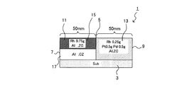
a)まず、本実施例1の排ガス浄化用触媒1の構成を図1を用いて説明する。尚、図1及び後述する図2〜14においてCZはCeリッチ複合酸化物を意味し、ZCはZrリッチ複合酸化物を意味し、Alはアルミナを意味し、Subは基板を意味する。
a) First, the structure of the exhaust gas-
排ガス浄化用触媒1は、基材(触媒基材)3の表面に触媒コート層5を形成したものである。基材3は、全長100mm、容積1.0L、セル数900セル/in2のモノリスハニカム基材であり、触媒コート層5は、基材3のセルの内面に形成されている。図1における左側の端部は、セルの入り口側端部7であり、右側の端部はセルの出口側端部9である。従って、入り口側端部7から出口側端部9に向かう方向が排ガスの流れ方向である。
The exhaust gas-
触媒コート層5は、入り口側端部7から50mmまでの部分である上流部11と、出口側端部9から50mmまでの部分(すなわち、上流部11における最下流側から出口側端部9までの部分)である下流部13とから成る。さらに、上流部11は、上流部外層15と上流部内層17とから成る。
The
上流部外層15は貴金属としてのRh(0.75g)、アルミナ、及びZrリッチ複合酸化物から成る。上流部内層17はアルミナ及びCeリッチ複合酸化物(耐火性無機酸化物)から成る。下流部13は、貴金属としてのRh(0.25g)、Pd(1.0g)、アルミナ、及びZrリッチ複合酸化物(耐火性無機酸化物)から成る。
The upstream
b)次に、本実施例1の排ガス浄化用触媒1を製造する方法を説明する。
まず、以下のようにしてスラリーS1A、S1B、S1Cを製造した。
(スラリーS1A)
次の成分を混合することによりスラリーS1Aを製造した。
b) Next, a method for producing the exhaust gas-
First, slurries S1A, S1B, and S1C were manufactured as follows.
(Slurry S1A)
Slurry S1A was manufactured by mixing the following components.
アルミナ:25g
Ceリッチ複合酸化物(CeO2の組成比が80wt%):25g
水:50g
(スラリーS1B)
次の成分を混合することによりスラリーS1Bを製造した。
Alumina: 25g
Ce-rich composite oxide (composition ratio of CeO 2 is 80 wt%): 25 g
Water: 50g
(Slurry S1B)
Slurry S1B was manufactured by mixing the following components.
アルミナ:25g
Zrリッチ複合酸化物(ZrO2の組成比が80wt%):25g
硝酸Rh溶液:Rhで0.75gとなる量
水:50g
(スラリーS1C)
次の成分を混合することによりスラリーS1Cを製造した。
Alumina: 25g
Zr rich composite oxide (composition ratio of ZrO 2 is 80 wt%): 25 g
Nitric acid Rh solution: RH amount of 0.75 g Water: 50 g
(Slurry S1C)
Slurry S1C was manufactured by mixing the following components.
アルミナ:50g
Zrリッチ複合酸化物(ZrO2の組成比が80wt%):50g
硝酸Rh溶液:Rhで0.25gとなる量
硝酸Pd溶液:Pdで1.0gとなる量
水:100g
次に、基材3のセルにおける入り口側端部7から50mmまでの領域に、スラリーS1Aを50gコートし、250℃で1時間乾燥させた後、500℃で1時間焼成した。この工程により上流部内層17が形成された。尚、乾燥、焼成の条件は以下においても同様とする。尚、本願明細書におけるスラリーのコート量の記載は固形分の重量を意味する。
Alumina: 50g
Zr rich composite oxide (composition ratio of ZrO 2 is 80 wt%): 50 g
Nitric acid Rh solution: amount of 0.25 g in Rh Nitric acid Pd solution: amount of 1.0 g in Pd Water: 100 g
Next, 50 g of slurry S1A was coated on the area of the
次に、先にスラリーS1Aをコートした領域に、スラリーS1Bを50.75g(そのうち、Rhの量は0.75g)コートし、250℃で1時間乾燥させた後、500℃で1時間焼成した。この工程により上流部外層15が形成された。
Next, 50.75 g of the slurry S1B (of which the amount of Rh is 0.75 g) is coated on the area where the slurry S1A was previously coated, dried at 250 ° C. for 1 hour, and then fired at 500 ° C. for 1 hour. . The upstream
次に、基材3のセルにおける出口側端部9から50mmの部分までの領域(すなわち、スラリーS1A、S1Bをコートしていない部分)に、スラリーS1Cを101.25g(そのうち、Rhの量は0.25g、Pdの量は1.0g)コートし、250℃で1時間乾燥させた後、500℃で1時間焼成した。この工程により下流部13が形成され、排ガス浄化用触媒1が完成した。
Next, 101.25 g of the slurry S1C (of which the amount of Rh is the amount of Rh) 0.25 g, the amount of Pd was 1.0 g), dried at 250 ° C. for 1 hour, and then fired at 500 ° C. for 1 hour. The
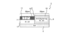
本実施例2の排ガス浄化用触媒1の構成は、図2に示すように、基本的には前記実施例1と同様であるが、下流部13に含まれる貴金属が、Rh0.25gとPt1.0gとである点で相違する。
As shown in FIG. 2, the configuration of the exhaust
本実施例2の排ガス浄化用触媒1の製造方法は、基本的には前記実施例1と同様であるが、スラリーS1Cの代わりに、下記の各成分を混合したスラリーS2を用いた。
(スラリーS2)
アルミナ:50g
Zrリッチ複合酸化物(ZrO2の組成比が80wt%):50g
硝酸Rh溶液:Rhで0.25gとなる量
硝酸Pt溶液:Ptで1.0gとなる量
水:100g
本実施例2では、このスラリーS2を、基材3のセルにおける出口側端部9から50mmの部分までの領域に101.25g(そのうち、Rhの量は0.25g、Ptの量は1.0g)コートし、乾燥、焼成することで下流部13を形成した。尚、上流部11を形成する方法は前記実施例1と同様である。
The manufacturing method of the exhaust gas-
(Slurry S2)
Alumina: 50g
Zr rich composite oxide (composition ratio of ZrO 2 is 80 wt%): 50 g
Nitric acid Rh solution: amount of 0.25 g in Rh Nitric acid Pt solution: amount of 1.0 g in Pt Water: 100 g
In this Example 2, 101.25 g of this slurry S2 in the region from the outlet side end portion 9 to the 50 mm portion in the cell of the base material 3 (of which the amount of Rh is 0.25 g and the amount of Pt is 1. 0g) The
本実施例3の排ガス浄化用触媒1の構成は、図3に示すように、基本的には前記実施例1と同様であるが、下流部13に含まれる貴金属が、Rh0.25g、Pt0.5g、及びPd0.5gである点で相違する。
The configuration of the exhaust
本実施例3の排ガス浄化用触媒1の製造方法は、基本的には前記実施例1と同様であるが、スラリーS1Cの代わりに、下記の各成分を混合したスラリーS3を用いた。
(スラリーS3)
アルミナ:50g
Zrリッチ複合酸化物(ZrO2の組成比が80wt%):50g
硝酸Rh溶液:Rhで0.25gとなる量
硝酸Pd溶液:Pdで0.5gとなる量
硝酸Pt溶液:Ptで0.5gとなる量
水:100g
本実施例3では、このスラリーS3を、基材3のセルにおける出口側端部9から50mmの部分までの領域に101.25g(そのうち、Rhの量は0.25g、Pdの量は0.5g、Ptの量は0.5g)コートし、乾燥、焼成することで下流部13を形成した。尚、上流部11を形成する方法は前記実施例1と同様である。
The manufacturing method of the exhaust gas-
(Slurry S3)
Alumina: 50g
Zr rich composite oxide (composition ratio of ZrO 2 is 80 wt%): 50 g
Nitric acid Rh solution: Amount of 0.25 g of Rh Nitric acid Pd solution: Amount of 0.5 g of Pd Nitric acid Pt solution: Amount of 0.5 g of Pt Water: 100 g
In Example 3, 101.25 g of this slurry S3 in the region from the outlet side end portion 9 to the 50 mm portion in the cell of the base material 3 (of which the amount of Rh is 0.25 g and the amount of Pd is 0.1. The
本実施例4の排ガス浄化用触媒1の構成は、図4に示すように、基本的には前記実施例1と同様であるが、上流部内層17に貴金属としてのPd1.0gが含まれる点と、下流部13に含まれる貴金属がRh0.25gのみである点で相違する。
As shown in FIG. 4, the configuration of the exhaust
本実施例4の排ガス浄化用触媒1の製造方法は、基本的には前記実施例1と同様であるが、スラリーS1Aの代わりに、下記の各成分を混合したスラリーS4Aを用いた。また、スラリーS1Cの代わりに、下記の各成分を混合したスラリーS4Bを用いた。
(スラリーS4A)
アルミナ:25g
Ceリッチ複合酸化物(CeO2の組成比が80wt%):25g
硝酸Pd溶液:Pdで1.0gとなる量
水:50g
(スラリーS4B)
アルミナ:50g
Zrリッチ複合酸化物(ZrO2の組成比が80wt%):50g
硝酸Rh溶液:Rhで0.25gとなる量
水:100g
本実施例4では、上記のスラリーS4Aを、スラリーS1Aの代わりに、基材3のセルにおける入り口側端部7から50mmまでの領域に51g(そのうち、Pdの量は1.0g)コートし、乾燥、焼成することで上流部内層17を形成した。
The production method of the exhaust gas-
(Slurry S4A)
Alumina: 25g
Ce-rich composite oxide (composition ratio of CeO 2 is 80 wt%): 25 g
Nitric acid Pd solution: Amount of 1.0 g of Pd Water: 50 g
(Slurry S4B)
Alumina: 50g
Zr rich composite oxide (composition ratio of ZrO 2 is 80 wt%): 50 g
Nitric acid Rh solution: Amount of 0.25 g Rh Water: 100 g
In this Example 4, instead of the slurry S1A, 51 g (of which the amount of Pd is 1.0 g) is applied to a region from the inlet
また、上記スラリーS4Bを、スラリーS1Cの代わりに、基材3のセルにおける出口側端部9から50mmまでの領域に100.25g(そのうち、Rhの量は0.25g)コートし、乾燥、焼成することで下流部13を形成した。
Further, the slurry S4B is coated with 100.25 g (of which the amount of Rh is 0.25 g) in an area from the outlet side end portion 9 to 50 mm in the cell of the
尚、上流部内層17の形成後に、上流部外層15を形成する方法は前記実施例1と同様である。
The method for forming the upstream
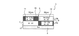
a)本実施例5の排ガス浄化用触媒1の構成は、図5に示すように、基本的には前記実施例1と同様であるが、下流部13が、下流部内層13aと、下流部外層13bとに分けられ、貴金属としてのRh0.25gとPd1.0gとが、下流部外層13bのみに含まれるという点で相違する。
a) The configuration of the exhaust
b)本実施例5の排ガス浄化用触媒1の製造方法は、基本的には前記実施例1と同様であるが、下流部13の形成方法において相違する。以下では、その相違点を中心に説明する。
b) The method for producing the exhaust
まず、下流部13を形成するために用いるスラリーとして、下記の各成分を混合したスラリーS5A及びスラリーS5Bを製造した。
(スラリーS5A)
アルミナ:25g
Zrリッチ複合酸化物(ZrO2の組成比が80wt%):25g
水:50g
(スラリーS5B)
アルミナ:25g
Zrリッチ複合酸化物(ZrO2の組成比が80wt%):25g
硝酸Rh溶液:Rhで0.25gとなる量
硝酸Pd溶液:Pdで1.0gとなる量
水:50g
次に、前記実施例1と同様にして、スラリーS1A及びスラリーS1Bを用い、上流部内層17及び上流部外層15を形成した。
First, as a slurry used to form the
(Slurry S5A)
Alumina: 25g
Zr rich composite oxide (composition ratio of ZrO 2 is 80 wt%): 25 g
Water: 50g
(Slurry S5B)
Alumina: 25g
Zr rich composite oxide (composition ratio of ZrO 2 is 80 wt%): 25 g
Nitric acid Rh solution: amount of 0.25 g in Rh Nitric acid Pd solution: amount of 1.0 g in Pd Water: 50 g
Next, in the same manner as in Example 1, the upstream
次に、基材3のセルにおける出口側端部9から50mmの部分までの領域(すなわち、スラリーS1A、1Bをコートしていない部分)に、スラリーS5Aを50gコートし、250℃で1時間乾燥させた後、500℃で1時間焼成した。この工程により下流部内層13aが形成された。
Next, 50 g of the slurry S5A is coated on the region from the outlet side end portion 9 to the 50 mm portion (that is, the portion where the slurry S1A, 1B is not coated) in the cell of the
次に、上記のスラリーS5Bを、先にスラリーS5Aをコートした領域に、51.25g(そのうち、Rhの量は0.25g、Pdの量は1.0g)コートし、乾燥、焼成することで下流部外層13bを形成し、排ガス浄化用触媒1を完成した。
Next, 51.25 g (of which the amount of Rh is 0.25 g and the amount of Pd is 1.0 g) is coated on the area where the slurry S5B is previously coated with the slurry S5B, and then dried and fired. The downstream
本実施例6の排ガス浄化用触媒1の構成は、図6に示すように、基本的には前記実施例5と同様であるが、下流部内層13aに貴金属としてのPd1.0gが含まれるという点、下流部外層13bに含まれる貴金属がRh0.25gのみである点において相違する。
The configuration of the exhaust
本実施例6の排ガス浄化用触媒1の製造方法は、基本的には前記実施例5と同様であるが、スラリーS5Aの代わりに、下記の各成分を混合したスラリーS6Aを用いた。また、スラリーS5Bの代わりに、下記の各成分を混合したスラリーS6Bを用いた。
(スラリーS6A)
アルミナ:25g
Zrリッチ複合酸化物(ZrO2の組成比が80wt%):25g
硝酸Pd溶液:Pdで1.0gとなる量
水:50g
(スラリーS6B)
アルミナ:25g
Zrリッチ複合酸化物(ZrO2の組成比が80wt%):25g
硝酸Rh溶液:Rhで0.25gとなる量
水:50g
本実施例6では、上記のスラリーS6Aを、スラリーS5Aの代わりに、基材3のセルにおける出口側端部9から50mmまでの領域に51g(そのうち、Pdの量は1.0g)コートし、乾燥、焼成することで下流部内層13aを形成した。
The manufacturing method of the exhaust gas-
(Slurry S6A)
Alumina: 25g
Zr rich composite oxide (composition ratio of ZrO 2 is 80 wt%): 25 g
Nitric acid Pd solution: Amount of 1.0 g of Pd Water: 50 g
(Slurry S6B)
Alumina: 25g
Zr rich composite oxide (composition ratio of ZrO 2 is 80 wt%): 25 g
Nitric acid Rh solution: Amount to be 0.25 g in Rh Water: 50 g
In Example 6, instead of the slurry S6A, 51 g (of which the amount of Pd is 1.0 g) is applied to the region from the outlet side end 9 in the cell of the
次に、上記スラリーS6Bを、先にスラリーS6Aをコートした領域に50.25g(そのうち、Rhの量は0.25g)コートし、乾燥、焼成することで下流部外層13bを形成した。尚、上流部11を形成する方法は前記実施例5と同様である。
Next, 50.25 g (of which the amount of Rh was 0.25 g) of the slurry S6B previously coated on the slurry S6A was coated, dried and fired to form the downstream portion
本実施例7の排ガス浄化用触媒1の構成は、図7に示すように、基本的には前記実施例1と同様であるが、上流部11のコート量が50.75gであり、下流部13のコート量101.25gよりも少ないという点で相違する。
The configuration of the exhaust
本実施例7の排ガス浄化用触媒1の製造方法は、基本的には前記実施例1と同様であるが、上流部内層17を形成する際のスラリーS1Aのコート量を25gとする点、及びスラリーS1Bの代わりに、下記の各成分を混合したスラリーS7Aを用いる点で相違する。
(スラリーS7A)
アルミナ:12.5g
Zrリッチ複合酸化物(ZrO2の組成比が80wt%):12.5g
硝酸Rh溶液:Rhで0.75gとなる量
水:25g
本実施例7では、基材3のセルにおける入り口側端部7から50mmまでの領域に、スラリーS1Aを25gコートし、250℃で1時間乾燥させた後、500℃で1時間焼成することで上流部内層17を形成した。
The manufacturing method of the exhaust gas-
(Slurry S7A)
Alumina: 12.5g
Zr rich composite oxide (composition ratio of ZrO 2 is 80 wt%): 12.5 g
Nitric acid Rh solution: RH amount of 0.75 g Water: 25 g
In Example 7, 25 g of slurry S1A was coated on the area from the
次に、上記のスラリーS7Aを、先にスラリーS1Aをコートした領域に25.75g(そのうち、Rhの量は0.75g)コートし、乾燥、焼成することで上流部外層15を形成した。尚、下流部13の形成方法は前記実施例1と同様である。
Next, 25.75 g (of which the amount of Rh was 0.75 g) of the above-mentioned slurry S7A was coated on the area where the slurry S1A was previously coated, and dried and fired to form the upstream
本実施例8の排ガス浄化用触媒1の構成は、図8に示すように、基本的には前記実施例1と同様であるが、上流部内層17、上流部外層15、及び下流部13のそれぞれに、バリウムとランタンを含む点で相違する。
As shown in FIG. 8, the configuration of the exhaust
本実施例8の排ガス浄化用触媒1の製造方法は、基本的には前記実施例1と同様であるが、スラリーS1Aの代わりに、下記の各成分を混合したスラリーS8Aを用いた。また、スラリーS1Bの代わりに、下記の各成分を混合したスラリーS8Bを用いた。また、スラリーS1Cの代わりに、下記の各成分を混合したスラリーS8Cを用いた。
(スラリーS8A)
アルミナ:25g
Ceリッチ複合酸化物(CeO2の組成比が80wt%):25g
硫酸バリウム:5g
炭酸ランタン:2.5g
水:57.5g
(スラリーS8B)
アルミナ:25g
Zrリッチ複合酸化物(ZrO2の組成比が80wt%):25g
硫酸バリウム:5g
炭酸ランタン:2.5g
硝酸Rh溶液:Rhで0.75gとなる量
水:82.5g
(スラリーS8C)
アルミナ:50g
Zrリッチ複合酸化物(ZrO2の組成比が80wt%):50g
硫酸バリウム:10g
炭酸ランタン:5g
硝酸Rh溶液:Rhで0.25gとなる量
硝酸Pd溶液:Pdで1.0gとなる量
水:115g
本実施例8では、上記のスラリーS8Aを、スラリーS1Aの代わりに、基材3のセルにおける入り口側端部7から50mmまでの領域に57.5gコートし、乾燥、焼成することで上流部内層17を形成した。
The manufacturing method of the exhaust gas-
(Slurry S8A)
Alumina: 25g
Ce-rich composite oxide (composition ratio of CeO 2 is 80 wt%): 25 g
Barium sulfate: 5g
Lanthanum carbonate: 2.5g
Water: 57.5g
(Slurry S8B)
Alumina: 25g
Zr rich composite oxide (composition ratio of ZrO 2 is 80 wt%): 25 g
Barium sulfate: 5g
Lanthanum carbonate: 2.5g
Nitric acid Rh solution: RH amount of 0.75 g Water: 82.5 g
(Slurry S8C)
Alumina: 50g
Zr rich composite oxide (composition ratio of ZrO 2 is 80 wt%): 50 g
Barium sulfate: 10g
Lanthanum carbonate: 5g
Nitric acid Rh solution: amount of 0.25 g in Rh Nitric acid Pd solution: amount of 1.0 g in Pd Water: 115 g
In Example 8, instead of the slurry S1A, 57.5 g of the slurry S8A is coated on the region from the
次に、上記のスラリーS8Bを、先にスラリーS8Aをコートした領域に58.25g(そのうち、Rhの量は0.75g)コートし、乾燥、焼成することで上流部外層15を形成した。
Next, the upstream
次に、上記スラリーS8Cを、基材3のセルにおける出口側端部9から50mmまでの領域に116.25g(そのうち、Rhの量は0.25g、Pdの量は1.0g)コートし、乾燥、焼成することで下流部13を形成した。
Next, 116.25 g (of which the amount of Rh is 0.25 g and the amount of Pd is 1.0 g) of the slurry S8C is coated on an area from the outlet side end portion 9 to 50 mm in the cell of the
本実施例9の排ガス浄化用触媒1の構成は、図9に示すように、基本的には前記実施例1と同様であるが、貴金属としてのRhが上流部外層15における表面側(外側)に偏在している。つまり、上流部外層15の厚みは約100μmであるが、Rhは、上流部外層15の表面から深さ約10μmまでの範囲に全て担持されている。
The configuration of the exhaust gas-
本実施例9の排ガス浄化用触媒1は次のようにして製造できる。
まず、スラリーS1Aを、前記実施例1と同様の基材3のセルにおける入り口側端部7から50mmまでの領域に50gコートし、250℃で1時間乾燥させた後、500℃で1時間焼成することで上流部内層17を形成した。
The exhaust gas-
First, 50 g of the slurry S1A is coated on a region from the
次に、スラリーS5Aを、先にスラリーS1Aをコートした領域に50gコートし、250℃で1時間乾燥させた後、500℃で1時間焼成した。焼成後、硝酸Rh溶液を用いて、先にスラリーS1A及びスラリーS5Aをコートした領域にRhを0.75g担持させ、250℃で1時間乾燥させた。 Next, 50 g of the slurry S5A was coated on the area previously coated with the slurry S1A, dried at 250 ° C. for 1 hour, and then fired at 500 ° C. for 1 hour. After firing, 0.75 g of Rh was supported on the area previously coated with slurry S1A and slurry S5A using a Rh nitrate solution and dried at 250 ° C. for 1 hour.
次に、スラリーS5Aを、基材3のセルにおける出口側端部9から50mmまでの領域に100gコートし、250℃で1時間乾燥させた後、500℃で1時間焼成した。焼成後、硝酸Rh溶液及び硝酸Pt溶液を用いて、先にスラリーS5Aをコートした領域(出口側端部9から50mmまでの領域)にRhを0.25g、Ptを1.0g担持させ、250℃で1時間乾燥して排ガス浄化用触媒1を完成した。
(比較例1)
本比較例1の排ガス浄化用触媒1の構成を図10を用いて説明する。排ガス浄化用触媒1は、前記実施例1と同様の基材3のセル表面に触媒コート層5を備える。触媒コート層は、前記実施例1と同様に、上流部内層17、上流部外層15、下流部13を備えている。上流部内層17はアルミナ、及びZrリッチ複合酸化物から成る。上流部外層15は貴金属としてのRh(0.75g)、アルミナ、及びCeリッチ複合酸化物から成る。下流部13は、貴金属としてのRh(0.25g)、Pd(1.0g)、アルミナ、及びZrリッチ複合酸化物から成る。
Next, 100 g of slurry S5A was coated on a region of the
(Comparative Example 1)
The structure of the exhaust gas-
b)次に、本比較例1の排ガス浄化用触媒1を製造する方法を説明する。
まず、スラリーS5Aを、基材3のセルにおける入り口側端部7から50mmまでの領域に50gコートし、250℃で1時間乾燥させた後、500℃で1時間焼成して上流部内層17を形成した。
b) Next, a method for producing the exhaust gas-
First, 50 g of slurry S5A is coated on the area of the
次に、先にスラリーS5Aをコートした領域に、下記に示すスラリーSP1を50.75g(そのうち、Rhの量は0.75g)コートし、250℃で1時間乾燥させた後、500℃で1時間焼成して上流部外層15を形成した。
(スラリーSP1)
アルミナ:25g
Ceリッチ複合酸化物(CeO2の組成比が80wt%):25g
硝酸Rh溶液:Rhで0.75g
水:50g
次に、スラリーS1Cを、基材3のセルにおける出口側端部9から50mmまでの領域に101.25g(そのうち、Rhの量は0.25g、Pdの量は1.0g)コートし、250℃で1時間乾燥させた後、500℃で1時間焼成して下流部13を形成した。
(比較例2)
本比較例2の排ガス浄化用触媒1の構成は、図11に示すように、基本的には前記比較例1と同様であるが、上流部外層15が、Ceリッチ複合酸化物ではなく、Zrリッチ複合酸化物を含む点で相違する。
Next, 50.75 g of the slurry SP1 shown below (of which the amount of Rh is 0.75 g) is coated on the area previously coated with the slurry S5A, dried at 250 ° C. for 1 hour, and then 1 at 500 ° C. The upstream
(Slurry SP1)
Alumina: 25g
Ce-rich composite oxide (composition ratio of CeO 2 is 80 wt%): 25 g
Nitric acid Rh solution: 0.75 g in Rh
Water: 50g
Next, 101.25 g (of which the amount of Rh is 0.25 g and the amount of Pd is 1.0 g) of the slurry S1C is coated on a region from the outlet side end portion 9 to 50 mm in the cell of the
(Comparative Example 2)
As shown in FIG. 11, the configuration of the exhaust gas-
本比較例2の排ガス浄化用触媒1の製造方法は、基本的には前記比較例1と同様であるが、上流部外層15を形成するために、スラリーSP1の代わりに、スラリーS1Bを50.75g(そのうち、Rhの量は0.75g)コートする。
(比較例3)
本比較例3の排ガス浄化用触媒1の構成は、図12に示すように、基本的には前記比較例1と同様であるが、上流部外層15に含まれるRhの量が0.25gであり、下流部13に含まれるRhの量が0.75gである点で相違する。また、上流部内層17が、Zrリッチ複合酸化物ではなく、Ceリッチ複合酸化物を含み、上流部外層15がCeリッチ複合酸化物ではなく、Zrリッチ複合酸化物を含む点で相違する。
The manufacturing method of the exhaust gas-
(Comparative Example 3)
The configuration of the exhaust
本比較例3の排ガス浄化用触媒1の製造方法は、基本的には前記比較例1と同様であるが一部において相違する。すなわち、上流部内層17を形成するために、スラリーS5Aの代わりに、スラリーS1Aを50gコートした。また、上流部外層15を形成するために、スラリーSP1の代わりに、スラリーS6Bを50.25g(そのうち、Rhの量は0.25g)コートした。また、下流部13を形成するために、スラリーS1Cの代わりに、下記に示すスラリーSP3(そのうち、Rhの量は0.75g、Pdの量は1.0g)を101.75gコートした。
(スラリーSP3)
アルミナ:50g
Zrリッチ複合酸化物(ZrO2の組成比が80wt%):50g
硝酸Rh溶液:Rhで0.75g
硝酸Pd溶液:Pdで1.0g
水:75g
(比較例4)
本比較例4の排ガス浄化用触媒1の構成は、図13に示すように、基本的には前記比較例1と同様であるが、上流部外層15に含まれるRhの量が0.5gであるとともに、耐火性無機酸化物がZrリッチ複合酸化物である点で相違する。また、下流部13に含まれるRhの量が0.5gである点で相違する。
The manufacturing method of the exhaust gas-
(Slurry SP3)
Alumina: 50g
Zr rich composite oxide (composition ratio of ZrO 2 is 80 wt%): 50 g
Nitric acid Rh solution: 0.75 g in Rh
Nitric acid Pd solution: 1.0 g of Pd
Water: 75g
(Comparative Example 4)
As shown in FIG. 13, the configuration of the exhaust gas-
本比較例4の排ガス浄化用触媒1の製造方法は、基本的には前記比較例1と同様であるが一部において相違する。すなわち、上流部外層15を形成するために、スラリーSP1の代わりに、下記に示すスラリーSP4Aを50.5g(そのうち、Rhの量は0.5g)コートした。
(スラリーSP4A)
アルミナ:25g
Zrリッチ複合酸化物(ZrO2の組成比が80wt%):25g
硝酸Rh溶液:Rhで0.5g
水:50g
また、下流部13を形成するために、スラリーS1Cの代わりに、下記に示すスラリーSP4Bを101.5g(そのうち、Rhの量は0.5g、Pdの量は1.0g)コートした。
(スラリーSP4B)
アルミナ:50g
Zrリッチ複合酸化物(ZrO2の組成比が80wt%):50g
硝酸Rh溶液:Rhで0.5g
硝酸Pd溶液:Pdで1.0g
水:100g
(比較例5)
本比較例5の排ガス浄化用触媒1の構成は図14に示すように、前記実施例1と同様の基材3のセル表面に触媒コート層5を備える。触媒コート層5は、実施例1〜9とは異なり、上流部/下流部に分かれていない。また、触媒コート層5は、内層19と外層21との2層構造を有している。内層19は、アルミナ、Ceリッチ複合酸化物、及び貴金属としてのPdを1.0g含んでいる。外層21は、アルミナ、Zrリッチ複合酸化物、及び貴金属としてのRhを1.0g含んでいる。
The manufacturing method of the exhaust gas-
(Slurry SP4A)
Alumina: 25g
Zr rich composite oxide (composition ratio of ZrO 2 is 80 wt%): 25 g
Nitric acid Rh solution: 0.5g in Rh
Water: 50g
Moreover, in order to form the
(Slurry SP4B)
Alumina: 50g
Zr rich composite oxide (composition ratio of ZrO 2 is 80 wt%): 50 g
Nitric acid Rh solution: 0.5g in Rh
Nitric acid Pd solution: 1.0 g of Pd
Water: 100g
(Comparative Example 5)
As shown in FIG. 14, the configuration of the exhaust
本比較例5の排ガス浄化用触媒1は、次のように製造することができる。まず、前記実施例1と同様の基材3のセル全体に、下記に示すスラリーSP5Aを101.0g(そのうち、Pdの量は1.0g)コートし、250℃で1時間乾燥させた後、500℃で1時間焼成して、内層19を形成した。
(スラリーSP5A)
アルミナ:50g
Ceリッチ複合酸化物(CeO2の組成比が80wt%):50g
硝酸Pd溶液:Pdで1.0g
水:100g
次に、下記に示すスラリーSP5Bを、先にスラリーSP5Aをコートした領域に、101.0g(そのうち、Rhの量は1.0g)コートし、250℃で1時間乾燥させた後、500℃で1時間焼成して、外層21を形成した。
(スラリーSP5B)
アルミナ:50g
Zrリッチ複合酸化物(ZrO2の組成比が80wt%):50g
硝酸Rh溶液:Rhで1.0g
水:100g
上記実施例1〜9及び比較例1〜5について着火性を試験した。
(試験方法)
各実施例及び比較例の排ガス浄化用触媒を、8万Km相当の耐久試験を行ってから、排気量2.0Lのエンジンを有する実機車両に搭載した。そして、11モードを走行した時点でのHC、CO、NOxエミッションを測定した。
(試験結果)
試験結果を表1に示す。
The exhaust gas-
(Slurry SP5A)
Alumina: 50g
Ce-rich composite oxide (composition ratio of CeO 2 is 80 wt%): 50 g
Nitric acid Pd solution: 1.0 g of Pd
Water: 100g
Next, 101.0 g (of which the amount of Rh is 1.0 g) of the slurry SP5B shown below was coated on the area where the slurry SP5A was previously coated, dried at 250 ° C. for 1 hour, and then at 500 ° C. The outer layer 21 was formed by baking for 1 hour.
(Slurry SP5B)
Alumina: 50g
Zr rich composite oxide (composition ratio of ZrO 2 is 80 wt%): 50 g
Nitric acid Rh solution: 1.0 g in Rh
Water: 100g
The above Examples 1 to 9 and Comparative Examples 1 to 5 were tested for ignitability.
(Test method)
The exhaust gas purifying catalysts of each Example and Comparative Example were mounted on an actual vehicle having an engine with a displacement of 2.0 L after performing an endurance test equivalent to 80,000 km. HC, CO, and NOx emissions at the time when the vehicle traveled in the 11 mode were measured.
(Test results)
The test results are shown in Table 1.

表1に示すように、実施例1〜9の排ガス浄化用触媒は、比較例1〜5に比べて、HC、CO、NOxエミッションが顕著に少ない。特に、実施例4の排ガス浄化用触媒は、上流部内層17にPdを含むことにより、エミッションが一層少ない。また、実施例6の排ガス浄化用触媒は、下流部13が下流部内層13aと下流部外層13bに区分されるとともに、下流部内層13aにPdが含まれ、下流部外層13bにRhが含まれることにより、エミッションが一層少ない。また、実施例7の排ガス浄化用触媒は、上流部11の単位容積あたりのコート量が下流部13より少ないことにより、エミッションが一層少ない。また、実施例9の排ガス浄化用触媒は、上流部外層15及び下流部13において、貴金属がその上面付近に偏在していることにより、エミッションが一層少ない。
As shown in Table 1, the exhaust gas purifying catalysts of Examples 1 to 9 have significantly less HC, CO, and NOx emissions than Comparative Examples 1 to 5. In particular, the exhaust gas purifying catalyst of Example 4 contains Pd in the upstream
以上の実験から、本実施例1〜9の排ガス浄化用触媒の着火性が優れていることが確認できた。
尚、本発明は前記実施例になんら限定されるものではなく、本発明を逸脱しない範囲において種々の態様で実施しうることはいうまでもない。
From the above experiments, it was confirmed that the ignitability of the exhaust gas purifying catalysts of Examples 1 to 9 was excellent.
Needless to say, the present invention is not limited to the above-described embodiments, and can be implemented in various modes without departing from the scope of the present invention.
1・・・排ガス浄化用触媒
3・・・基材
5・・・触媒コート層
7・・・入り口側端部
9・・・出口側端部
11・・・上流部
13・・・下流部
13a・・・下流部内層
13b・・・下流部外層
15・・・上流部外層
17・・・上流部内層
DESCRIPTION OF
Claims (6)
貴金属及び耐火性無機酸化物を含み、前記触媒基材上に形成された触媒コート層と、
を有する排ガス浄化用触媒であって、
前記触媒コート層は、排ガスの流れ方向における上流に位置する上流部と、下流に位置する下流部とを有するとともに、
前記上流部は、上流部内層及び上流部外層を含む層構造を有し、
前記上流部内層は、耐火性無機酸化物として、CeO2の組成比が50〜95wt%であるセリウム・ジルコニウム複合酸化物を含み、前記上流部外層は、前記耐火性無機酸化物として、ZrO2の組成比が50〜95wt%であるセリウム・ジルコニウム複合酸化物を含み、
前記上流部外層及び前記下流部に、貴金属としてRhを含むとともに、前記上流部外層に含まれるRhの量が、前記下流部に含まれるRhよりも多いことを特徴とする排ガス浄化用触媒。 A catalyst substrate;
A catalyst coat layer comprising a noble metal and a refractory inorganic oxide and formed on the catalyst substrate;
An exhaust gas purifying catalyst having
The catalyst coat layer has an upstream portion located upstream in the flow direction of the exhaust gas and a downstream portion located downstream,
The upstream portion has a layer structure including an upstream portion inner layer and an upstream portion outer layer,
The upstream inner layer includes a cerium-zirconium composite oxide having a composition ratio of CeO 2 of 50 to 95 wt% as a refractory inorganic oxide, and the upstream outer layer includes ZrO 2 as a refractory inorganic oxide. A cerium-zirconium composite oxide having a composition ratio of 50 to 95 wt%,
An exhaust gas purifying catalyst, wherein the upstream outer layer and the downstream portion contain Rh as a noble metal, and the amount of Rh contained in the upstream outer layer is larger than that of Rh contained in the downstream portion.
前記下流部内層と前記下流部外層とでは、下記(A)及び/又は(B)が異なることを特徴とする請求項1又は2に記載の排ガス浄化用触媒。
(A)貴金属の種類及び/又は濃度
(B)耐火性無機酸化物の種類 The downstream part has a layer structure including a downstream part inner layer and a downstream part outer layer,
The exhaust gas purifying catalyst according to claim 1 or 2, wherein the downstream inner layer and the downstream outer layer are different in the following (A) and / or (B).
(A) Type and / or concentration of noble metal (B) Type of refractory inorganic oxide
Priority Applications (5)
| Application Number | Priority Date | Filing Date | Title |
|---|---|---|---|
| JP2005211494A JP4833605B2 (en) | 2005-07-21 | 2005-07-21 | Exhaust gas purification catalyst |
| EP06781195.0A EP1916031B1 (en) | 2005-07-21 | 2006-07-18 | Exhaust gas purifying catalyst |
| CN2006800266244A CN101227977B (en) | 2005-07-21 | 2006-07-18 | Exhaust gas purifying catalyst |
| PCT/JP2006/314182 WO2007010899A1 (en) | 2005-07-21 | 2006-07-18 | Exhaust gas purifying catalyst |
| US11/995,981 US8309488B2 (en) | 2005-07-21 | 2006-07-18 | Exhaust gas purifying catalyst |
Applications Claiming Priority (1)
| Application Number | Priority Date | Filing Date | Title |
|---|---|---|---|
| JP2005211494A JP4833605B2 (en) | 2005-07-21 | 2005-07-21 | Exhaust gas purification catalyst |
Publications (2)
| Publication Number | Publication Date |
|---|---|
| JP2007021456A JP2007021456A (en) | 2007-02-01 |
| JP4833605B2 true JP4833605B2 (en) | 2011-12-07 |
Family
ID=37668778
Family Applications (1)
| Application Number | Title | Priority Date | Filing Date |
|---|---|---|---|
| JP2005211494A Active JP4833605B2 (en) | 2005-07-21 | 2005-07-21 | Exhaust gas purification catalyst |
Country Status (5)
| Country | Link |
|---|---|
| US (1) | US8309488B2 (en) |
| EP (1) | EP1916031B1 (en) |
| JP (1) | JP4833605B2 (en) |
| CN (1) | CN101227977B (en) |
| WO (1) | WO2007010899A1 (en) |
Cited By (1)
| Publication number | Priority date | Publication date | Assignee | Title |
|---|---|---|---|---|
| JP2007038072A (en) * | 2005-08-01 | 2007-02-15 | Cataler Corp | Catalyst for cleaning exhaust gas |
Families Citing this family (29)
| Publication number | Priority date | Publication date | Assignee | Title |
|---|---|---|---|---|
| JP5582671B2 (en) * | 2006-04-21 | 2014-09-03 | 株式会社キャタラー | Exhaust gas purification catalyst, exhaust gas purification catalyst recovery method, and exhaust gas purification catalyst system |
| DE502007005188D1 (en) * | 2007-03-19 | 2010-11-11 | Umicore Ag & Co Kg | Double-layered three-way catalyst |
| FR2918706B1 (en) * | 2007-07-11 | 2009-10-30 | Peugeot Citroen Automobiles Sa | DEVICE FOR TREATING GASEOUS EMISSIONS OF AN ENGINE. |
| JP5183162B2 (en) * | 2007-11-15 | 2013-04-17 | 川崎重工業株式会社 | Exhaust purification device |
| US20090175773A1 (en) * | 2008-01-08 | 2009-07-09 | Chen Shau-Lin F | Multilayered Catalyst Compositions |
| JP5599141B2 (en) * | 2008-09-04 | 2014-10-01 | 株式会社キャタラー | Exhaust gas purification catalyst for motorcycles |
| JP5492448B2 (en) * | 2009-04-28 | 2014-05-14 | 株式会社キャタラー | Exhaust gas purification catalyst |
| JP5240275B2 (en) * | 2010-10-22 | 2013-07-17 | トヨタ自動車株式会社 | Exhaust gas purification catalyst |
| JP2014000516A (en) * | 2012-06-18 | 2014-01-09 | Cataler Corp | Carrier for supporting catalyst, supported catalyst for exhaust gas purification, and filter for exhaust gas purification |
| RU2015101508A (en) * | 2012-06-20 | 2016-08-10 | Тойота Дзидося Кабусики Кайся | SUBSTANCE OF CATALYST FOR CLEANING EXHAUST GAS, CATALYST FOR CLEANING EXHAUST GAS ON ITS BASIS AND METHOD OF PRODUCING SUBSTANCE OF CATALYST FOR CLEANING EXHAUST GAS |
| US9266092B2 (en) * | 2013-01-24 | 2016-02-23 | Basf Corporation | Automotive catalyst composites having a two-metal layer |
| JP5942894B2 (en) * | 2013-02-21 | 2016-06-29 | マツダ株式会社 | Method for producing exhaust gas purifying catalyst |
| JP6532823B2 (en) * | 2013-11-28 | 2019-06-19 | 株式会社キャタラー | Exhaust gas purification catalyst |
| WO2015087872A1 (en) | 2013-12-13 | 2015-06-18 | 株式会社キャタラー | Catalyst for cleaning exhaust gas |
| US9694348B2 (en) | 2013-12-13 | 2017-07-04 | Cataler Corporation | Exhaust cleaning catalyst |
| JP6034356B2 (en) * | 2014-12-12 | 2016-11-30 | トヨタ自動車株式会社 | Exhaust gas purification catalyst |
| CN108778491B (en) * | 2016-03-22 | 2021-04-20 | 株式会社科特拉 | Catalyst for exhaust gas purification |
| JP6724531B2 (en) * | 2016-05-02 | 2020-07-15 | 三菱自動車工業株式会社 | Exhaust gas purification catalyst for internal combustion engine |
| JP6724532B2 (en) * | 2016-05-02 | 2020-07-15 | 三菱自動車工業株式会社 | Exhaust gas purification catalyst manufacturing method and exhaust gas purification catalyst |
| EP3466541B1 (en) * | 2016-05-24 | 2020-09-16 | Cataler Corporation | Exhaust gas purifying catalyst |
| JP6569637B2 (en) * | 2016-10-14 | 2019-09-04 | トヨタ自動車株式会社 | Exhaust gas purification device for internal combustion engine |
| JP6753811B2 (en) * | 2017-04-19 | 2020-09-09 | トヨタ自動車株式会社 | Exhaust gas purification catalyst |
| JP6954796B2 (en) * | 2017-10-06 | 2021-10-27 | トヨタ自動車株式会社 | Exhaust gas purification catalyst for automobiles |
| JP6968972B2 (en) * | 2018-02-21 | 2021-11-24 | 株式会社キャタラー | Exhaust gas purification catalyst device |
| WO2020153309A1 (en) * | 2019-01-22 | 2020-07-30 | 三井金属鉱業株式会社 | Catalyst for purifying exhaust gas |
| JP7288331B2 (en) * | 2019-03-29 | 2023-06-07 | 株式会社キャタラー | Exhaust gas purification catalyst device |
| CN110918092B (en) * | 2019-11-14 | 2022-07-15 | 江门市大长江集团有限公司 | Sectional catalyst and preparation method thereof |
| CN114728235A (en) * | 2019-11-22 | 2022-07-08 | 巴斯夫公司 | Emission control catalyst article with PGM rich zone |
| US11788450B2 (en) * | 2020-10-30 | 2023-10-17 | Johnson Matthey Public Limited Company | TWC catalysts for gasoline engine exhaust gas treatments |
Family Cites Families (17)
| Publication number | Priority date | Publication date | Assignee | Title |
|---|---|---|---|---|
| CA1002508A (en) * | 1972-11-30 | 1976-12-28 | Takashi Ohara | Method for the production of noble metal catalysts |
| IT1070099B (en) * | 1975-09-23 | 1985-03-25 | Degussa | SUPPORTED MONOLITHIC CATALYST AND ARRANGEMENT OF SUPPORTED MONOLITHIC CATALYSTS FOR THE PURIFICATION OF THE EXHAUST GASES OF COMBUSTION ENGINES |
| CN1021412C (en) * | 1988-10-26 | 1993-06-30 | 中国科学院生态环境研究中心 | Complex rare-earth oxidate containing valuable metal type honeycomb catalyst and its preparation |
| JPH08103656A (en) * | 1994-10-06 | 1996-04-23 | N E Chemcat Corp | Catalyst for purification of exhaust gas and method therefor |
| JP3235640B2 (en) | 1995-11-09 | 2001-12-04 | 株式会社アイシーティー | Internal combustion engine exhaust gas purification catalyst |
| US6087298A (en) | 1996-05-14 | 2000-07-11 | Engelhard Corporation | Exhaust gas treatment system |
| US6165429A (en) | 1997-01-10 | 2000-12-26 | Toyota Jidosha Kabushiki Kaisha | Exhaust gas purifying catalyst and exhaust gas purifying method |
| JPH10296085A (en) * | 1997-04-30 | 1998-11-10 | Cataler Kogyo Kk | Exhaust gas-purifying catalyst |
| JP2000301000A (en) * | 1999-04-23 | 2000-10-31 | Toyota Central Res & Dev Lab Inc | Exhaust gas cleaning catalyst and its preparation |
| JP3688947B2 (en) | 1999-09-03 | 2005-08-31 | ダイハツ工業株式会社 | Exhaust gas purification catalyst |
| JP4459346B2 (en) * | 1999-12-09 | 2010-04-28 | 株式会社キャタラー | Exhaust gas purification catalyst |
| US6569392B1 (en) * | 2000-02-02 | 2003-05-27 | Ford Global Technologies Llc | Three-way rare earth oxide catalyst |
| US7276212B2 (en) | 2001-10-01 | 2007-10-02 | Engelhard Corporation | Exhaust articles for internal combustion engines |
| JP2003326170A (en) * | 2002-03-06 | 2003-11-18 | Nissan Motor Co Ltd | Exhaust gas purification catalyst, manufacturing method therefor, and exhaust gas purification method |
| US20040001781A1 (en) | 2002-06-27 | 2004-01-01 | Engelhard Corporation | Multi-zone catalytic converter |
| JP3795871B2 (en) * | 2003-03-20 | 2006-07-12 | 株式会社キャタラー | Exhaust gas purification catalyst system |
| JP4238056B2 (en) * | 2003-03-31 | 2009-03-11 | 三井金属鉱業株式会社 | Layered catalyst for exhaust gas purification |
-
2005
- 2005-07-21 JP JP2005211494A patent/JP4833605B2/en active Active
-
2006
- 2006-07-18 US US11/995,981 patent/US8309488B2/en active Active
- 2006-07-18 EP EP06781195.0A patent/EP1916031B1/en active Active
- 2006-07-18 WO PCT/JP2006/314182 patent/WO2007010899A1/en active Application Filing
- 2006-07-18 CN CN2006800266244A patent/CN101227977B/en active Active
Cited By (1)
| Publication number | Priority date | Publication date | Assignee | Title |
|---|---|---|---|---|
| JP2007038072A (en) * | 2005-08-01 | 2007-02-15 | Cataler Corp | Catalyst for cleaning exhaust gas |
Also Published As
| Publication number | Publication date |
|---|---|
| EP1916031B1 (en) | 2016-04-13 |
| JP2007021456A (en) | 2007-02-01 |
| CN101227977B (en) | 2010-12-08 |
| US8309488B2 (en) | 2012-11-13 |
| EP1916031A1 (en) | 2008-04-30 |
| CN101227977A (en) | 2008-07-23 |
| US20090124492A1 (en) | 2009-05-14 |
| EP1916031A4 (en) | 2011-11-16 |
| WO2007010899A1 (en) | 2007-01-25 |
Similar Documents
| Publication | Publication Date | Title |
|---|---|---|
| JP4833605B2 (en) | Exhaust gas purification catalyst | |
| JP5021188B2 (en) | Exhaust gas purification catalyst | |
| JP6964580B2 (en) | Exhaust gas purification catalyst | |
| JP7043398B2 (en) | Exhaust gas purification catalyst | |
| JP5386121B2 (en) | Exhaust gas purification catalyst device and exhaust gas purification method | |
| JP4838258B2 (en) | Exhaust gas purification catalyst | |
| JP5807782B2 (en) | Exhaust gas purification catalyst | |
| JP6855445B2 (en) | Exhaust gas purification catalyst | |
| KR101059807B1 (en) | Exhaust gas purification catalyst | |
| JP6864677B2 (en) | Exhaust gas purification catalyst | |
| JP4935219B2 (en) | Exhaust gas purification catalyst | |
| JP2012035206A (en) | Exhaust gas purifying catalyst | |
| JP4716087B2 (en) | Exhaust gas purification catalyst | |
| EP3632537A1 (en) | Exhaust gas purification catalyst device | |
| JP5876475B2 (en) | NOx storage catalyst with reduced Rh load | |
| JP6735912B2 (en) | Exhaust gas purification catalyst and exhaust gas purification method using the same | |
| JP6997838B1 (en) | Exhaust gas purification catalyst | |
| US20230294077A1 (en) | Method of producing catalyst for exhaust gas purification |
Legal Events
| Date | Code | Title | Description |
|---|---|---|---|
| A621 | Written request for application examination |
Free format text: JAPANESE INTERMEDIATE CODE: A621 Effective date: 20080515 |
|
| TRDD | Decision of grant or rejection written | ||
| A01 | Written decision to grant a patent or to grant a registration (utility model) |
Free format text: JAPANESE INTERMEDIATE CODE: A01 Effective date: 20110830 |
|
| A01 | Written decision to grant a patent or to grant a registration (utility model) |
Free format text: JAPANESE INTERMEDIATE CODE: A01 |
|
| A61 | First payment of annual fees (during grant procedure) |
Free format text: JAPANESE INTERMEDIATE CODE: A61 Effective date: 20110922 |
|
| R150 | Certificate of patent or registration of utility model |
Ref document number: 4833605 Country of ref document: JP Free format text: JAPANESE INTERMEDIATE CODE: R150 Free format text: JAPANESE INTERMEDIATE CODE: R150 |
|
| FPAY | Renewal fee payment (event date is renewal date of database) |
Free format text: PAYMENT UNTIL: 20140930 Year of fee payment: 3 |
|
| R250 | Receipt of annual fees |
Free format text: JAPANESE INTERMEDIATE CODE: R250 |
|
| R250 | Receipt of annual fees |
Free format text: JAPANESE INTERMEDIATE CODE: R250 |
|
| R250 | Receipt of annual fees |
Free format text: JAPANESE INTERMEDIATE CODE: R250 |
|
| R250 | Receipt of annual fees |
Free format text: JAPANESE INTERMEDIATE CODE: R250 |
|
| R250 | Receipt of annual fees |
Free format text: JAPANESE INTERMEDIATE CODE: R250 |
|
| R250 | Receipt of annual fees |
Free format text: JAPANESE INTERMEDIATE CODE: R250 |
|
| R250 | Receipt of annual fees |
Free format text: JAPANESE INTERMEDIATE CODE: R250 |
|
| R250 | Receipt of annual fees |
Free format text: JAPANESE INTERMEDIATE CODE: R250 |
|
| R250 | Receipt of annual fees |
Free format text: JAPANESE INTERMEDIATE CODE: R250 |
|
| R250 | Receipt of annual fees |
Free format text: JAPANESE INTERMEDIATE CODE: R250 |
|
| R250 | Receipt of annual fees |
Free format text: JAPANESE INTERMEDIATE CODE: R250 |