EP2010871B1 - Procédé pour déterminer et surveiller le niveau de remplissage d'un fluide dans un récipient - Google Patents
Procédé pour déterminer et surveiller le niveau de remplissage d'un fluide dans un récipient Download PDFInfo
- Publication number
- EP2010871B1 EP2010871B1 EP07728066.7A EP07728066A EP2010871B1 EP 2010871 B1 EP2010871 B1 EP 2010871B1 EP 07728066 A EP07728066 A EP 07728066A EP 2010871 B1 EP2010871 B1 EP 2010871B1
- Authority
- EP
- European Patent Office
- Prior art keywords
- echo
- curve
- echo signal
- procedure
- signal
- Prior art date
- Legal status (The legal status is an assumption and is not a legal conclusion. Google has not performed a legal analysis and makes no representation as to the accuracy of the status listed.)
- Active
Links
- 238000000034 method Methods 0.000 title claims description 79
- 238000012544 monitoring process Methods 0.000 title claims description 5
- 239000000523 sample Substances 0.000 claims description 98
- 238000005259 measurement Methods 0.000 claims description 58
- 230000005540 biological transmission Effects 0.000 claims description 9
- 238000002310 reflectometry Methods 0.000 claims description 7
- 230000001419 dependent effect Effects 0.000 claims description 5
- 230000004807 localization Effects 0.000 claims description 4
- 239000004020 conductor Substances 0.000 description 25
- 230000008569 process Effects 0.000 description 24
- 230000008878 coupling Effects 0.000 description 21
- 238000010168 coupling process Methods 0.000 description 21
- 238000005859 coupling reaction Methods 0.000 description 21
- 239000012535 impurity Substances 0.000 description 12
- 239000000463 material Substances 0.000 description 12
- 239000011521 glass Substances 0.000 description 10
- 230000007704 transition Effects 0.000 description 9
- 238000003745 diagnosis Methods 0.000 description 7
- 230000008719 thickening Effects 0.000 description 7
- 230000008901 benefit Effects 0.000 description 6
- 238000013459 approach Methods 0.000 description 5
- 230000002829 reductive effect Effects 0.000 description 5
- 238000007789 sealing Methods 0.000 description 5
- 230000008859 change Effects 0.000 description 4
- 230000007547 defect Effects 0.000 description 4
- 238000002592 echocardiography Methods 0.000 description 4
- 238000009434 installation Methods 0.000 description 4
- XLYOFNOQVPJJNP-UHFFFAOYSA-N water Substances O XLYOFNOQVPJJNP-UHFFFAOYSA-N 0.000 description 4
- 239000000919 ceramic Substances 0.000 description 3
- 238000011156 evaluation Methods 0.000 description 3
- 238000000691 measurement method Methods 0.000 description 3
- PNEYBMLMFCGWSK-UHFFFAOYSA-N Alumina Chemical compound [O-2].[O-2].[O-2].[Al+3].[Al+3] PNEYBMLMFCGWSK-UHFFFAOYSA-N 0.000 description 2
- 230000006978 adaptation Effects 0.000 description 2
- 230000032683 aging Effects 0.000 description 2
- 238000004891 communication Methods 0.000 description 2
- 238000005516 engineering process Methods 0.000 description 2
- 238000011835 investigation Methods 0.000 description 2
- 239000003550 marker Substances 0.000 description 2
- 230000035515 penetration Effects 0.000 description 2
- 239000004033 plastic Substances 0.000 description 2
- 229920003023 plastic Polymers 0.000 description 2
- 230000035945 sensitivity Effects 0.000 description 2
- 125000006850 spacer group Chemical group 0.000 description 2
- 239000000126 substance Substances 0.000 description 2
- 238000009423 ventilation Methods 0.000 description 2
- OKTJSMMVPCPJKN-UHFFFAOYSA-N Carbon Chemical compound [C] OKTJSMMVPCPJKN-UHFFFAOYSA-N 0.000 description 1
- 101150041326 air-2 gene Proteins 0.000 description 1
- 230000002238 attenuated effect Effects 0.000 description 1
- 230000006399 behavior Effects 0.000 description 1
- 238000005452 bending Methods 0.000 description 1
- 230000000903 blocking effect Effects 0.000 description 1
- 238000006243 chemical reaction Methods 0.000 description 1
- 239000011248 coating agent Substances 0.000 description 1
- 238000000576 coating method Methods 0.000 description 1
- 150000001875 compounds Chemical class 0.000 description 1
- 230000007797 corrosion Effects 0.000 description 1
- 238000005260 corrosion Methods 0.000 description 1
- 230000003247 decreasing effect Effects 0.000 description 1
- 238000013461 design Methods 0.000 description 1
- 230000000694 effects Effects 0.000 description 1
- 229920001971 elastomer Polymers 0.000 description 1
- 239000000806 elastomer Substances 0.000 description 1
- 230000005684 electric field Effects 0.000 description 1
- 239000000945 filler Substances 0.000 description 1
- 238000005187 foaming Methods 0.000 description 1
- 229910002804 graphite Inorganic materials 0.000 description 1
- 239000010439 graphite Substances 0.000 description 1
- 229910000856 hastalloy Inorganic materials 0.000 description 1
- 230000007062 hydrolysis Effects 0.000 description 1
- 238000006460 hydrolysis reaction Methods 0.000 description 1
- 238000002347 injection Methods 0.000 description 1
- 239000007924 injection Substances 0.000 description 1
- 230000002452 interceptive effect Effects 0.000 description 1
- 230000006386 memory function Effects 0.000 description 1
- 238000012856 packing Methods 0.000 description 1
- 230000036961 partial effect Effects 0.000 description 1
- 238000004886 process control Methods 0.000 description 1
- 238000005070 sampling Methods 0.000 description 1
- 230000011664 signaling Effects 0.000 description 1
- 229910001220 stainless steel Inorganic materials 0.000 description 1
- 239000010935 stainless steel Substances 0.000 description 1
- 230000035882 stress Effects 0.000 description 1
- 238000011144 upstream manufacturing Methods 0.000 description 1
- 238000012795 verification Methods 0.000 description 1
Images

Classifications
-
- G—PHYSICS
- G01—MEASURING; TESTING
- G01F—MEASURING VOLUME, VOLUME FLOW, MASS FLOW OR LIQUID LEVEL; METERING BY VOLUME
- G01F23/00—Indicating or measuring liquid level or level of fluent solid material, e.g. indicating in terms of volume or indicating by means of an alarm
- G01F23/22—Indicating or measuring liquid level or level of fluent solid material, e.g. indicating in terms of volume or indicating by means of an alarm by measuring physical variables, other than linear dimensions, pressure or weight, dependent on the level to be measured, e.g. by difference of heat transfer of steam or water
- G01F23/28—Indicating or measuring liquid level or level of fluent solid material, e.g. indicating in terms of volume or indicating by means of an alarm by measuring physical variables, other than linear dimensions, pressure or weight, dependent on the level to be measured, e.g. by difference of heat transfer of steam or water by measuring the variations of parameters of electromagnetic or acoustic waves applied directly to the liquid or fluent solid material
- G01F23/284—Electromagnetic waves
-
- G—PHYSICS
- G01—MEASURING; TESTING
- G01F—MEASURING VOLUME, VOLUME FLOW, MASS FLOW OR LIQUID LEVEL; METERING BY VOLUME
- G01F25/00—Testing or calibration of apparatus for measuring volume, volume flow or liquid level or for metering by volume
- G01F25/20—Testing or calibration of apparatus for measuring volume, volume flow or liquid level or for metering by volume of apparatus for measuring liquid level
-
- G—PHYSICS
- G01—MEASURING; TESTING
- G01S—RADIO DIRECTION-FINDING; RADIO NAVIGATION; DETERMINING DISTANCE OR VELOCITY BY USE OF RADIO WAVES; LOCATING OR PRESENCE-DETECTING BY USE OF THE REFLECTION OR RERADIATION OF RADIO WAVES; ANALOGOUS ARRANGEMENTS USING OTHER WAVES
- G01S7/00—Details of systems according to groups G01S13/00, G01S15/00, G01S17/00
- G01S7/02—Details of systems according to groups G01S13/00, G01S15/00, G01S17/00 of systems according to group G01S13/00
- G01S7/28—Details of pulse systems
- G01S7/285—Receivers
- G01S7/292—Extracting wanted echo-signals
- G01S7/2921—Extracting wanted echo-signals based on data belonging to one radar period
-
- G—PHYSICS
- G01—MEASURING; TESTING
- G01S—RADIO DIRECTION-FINDING; RADIO NAVIGATION; DETERMINING DISTANCE OR VELOCITY BY USE OF RADIO WAVES; LOCATING OR PRESENCE-DETECTING BY USE OF THE REFLECTION OR RERADIATION OF RADIO WAVES; ANALOGOUS ARRANGEMENTS USING OTHER WAVES
- G01S7/00—Details of systems according to groups G01S13/00, G01S15/00, G01S17/00
- G01S7/02—Details of systems according to groups G01S13/00, G01S15/00, G01S17/00 of systems according to group G01S13/00
- G01S7/40—Means for monitoring or calibrating
- G01S7/4052—Means for monitoring or calibrating by simulation of echoes
- G01S7/406—Means for monitoring or calibrating by simulation of echoes using internally generated reference signals, e.g. via delay line, via RF or IF signal injection or via integrated reference reflector or transponder
- G01S7/4078—Means for monitoring or calibrating by simulation of echoes using internally generated reference signals, e.g. via delay line, via RF or IF signal injection or via integrated reference reflector or transponder involving an integrated reference reflector or reference transponder
Definitions
- the invention relates to a method for determining and monitoring the level of a medium in a container with a level gauge, which are guided by at least one measuring probe in the direction of the medium and at least one boundary layer of the medium as useful echo signals by the method of time domain reflectometry high-frequency measurement signals or reflected at impurities as false echo signals and received.
- measuring devices are produced and sold under the name Levelflex, which operate according to a transit time measurement method and serve to determine the level of a medium in a container and / or monitor.
- Levelflex which operate according to a transit time measurement method and serve to determine the level of a medium in a container and / or monitor.
- TDR Time Domain Reflectometry
- the distance of the measuring device to the medium surface can be determined with reference to the propagation speed of the high-frequency measurement signal. Taking into account the geometry of the container interior of the level of the medium is then determined as a relative or absolute size.
- the advantage of time-domain reflectometry is the substantial independence of product properties such as density, dielectric constant or conductivity, of process conditions such as rough surfaces or foaming, as well as properties of the container, such as shape, size or internals.
- the transit time measurement method can essentially be divided into two determination methods: The first determination method is based on a transit time measurement which requires a pulse train modulated signal for the distance covered; A second widespread investigation is based on the determination of Frequency difference of the currently transmitted, continuously frequency modulated high frequency signal to the received, reflected high frequency signal (FMCW - Frequency Modulated Continuous Wave). In general, the following is not limited to a specific investigation.
- the precise determination of the measuring position of the filling level in the echo curve depends on the measuring accuracy that can be achieved with this echo measuring principle under the given measuring conditions.
- One approach to determining the level is to determine the useful echo signal in the echo curve with the largest amplitude. Under real measuring conditions, however, it is often not possible to determine the exact filling level in the container, since, for example, the reference point can not be determined exactly and / or the propagation time of the measuring signal varies along the waveguide.
- a reference reflection is usually used to determine the reference point of the transit time measurement.
- a reflection sites are local changes to the waveguide or in the vicinity of the waveguide, such.
- impurities on waveguides or probes is the calibration of the propagation time of the measurement signals along the waveguide of a level gauge. These defects are usually caused by a change in the probe geometry.
- a number of impurities on the waveguide can be used. These impurities are attached, for example, in the measuring active region of the sensor, in particular in the US 3,398,578 .
- Another possibility for calibrating a transit time measurement with a TDR fill level measuring device can be two impurities, one being arranged at the transition of the measurement-inactive region to the active region and one in the measurement-active region, as in FIG US 3,474,337 and the US 5,249,463 cited, or wherein one is arranged in the messinmoden area of the sensor and one in the measuring active area, as in US 6,867,729 B2 was shown.
- a disadvantage of all these types of determination of the level is that the reference point is dependent on the process conditions and the measurement conditions, whereby the level of the medium in a container due to the undefined reference point or zero point can not be determined accurately.
- the object of the invention is to provide a method with which an exact determination of the level and thus an increased measurement reliability and Reliability of the measurement is achieved with the level gauge.
- a method for determining and monitoring the level of a medium in a container with a level gauge which are guided by at least one boundary layer of the medium by at least one measuring probe by the method of time domain reflectometry high-frequency measurement signals Means reflected as useful echo signals or impurities as spurious echo signals and received, which method comprises the following steps, wherein a reference echo signal is formed in a Meßin2011en range of the level meter either from a transmission pulse of the high-frequency measurement signal or one of the false echo signals, wherein from the useful echo signals, the reference echo signal and the spurious echo signals from the running time or the running distance dependent current echo curve is formed, wherein at least from a first spurious echo signal and the reference echo signal, in a messinattentionen Berei caused by the level measuring device, a reference point is located in the current echo curve, wherein the filling level is determined from the distance of the useful echo signal formed in a measuring active range of the level measuring device to the reference point in the current echo curve.
- a coarse determination of the reference point is performed on the basis of the reference echo signal having a first high amplitude.
- Another preferred embodiment of the method according to the invention performs a fine determination of the reference point on the basis of the first false echo signal having a second lower amplitude.
- the current echo curve which is shifted by the first clutter echo signal of the current echo curve is shifted to a predetermined initial position of the first clutter echo signal.
- a supplementary embodiment of the method according to the invention allows the shifted echo curve is stored cyclically, event-controlled or manually as a history echo curve.
- the shifted echo curve is displayed together with the stored history echo curve.
- Another preferred embodiment of the method according to the invention takes into account that a functional diagnosis of the level measuring device is carried out on the basis of the determination of the distance and / or the curve shape of the reference echo signal and the first false echo signal in the current echo curve and / or shifted echo curve.
- At least one third false echo signal in the current echo curve and / or shifted echo curve is determined in a measuring-active region of the level-measuring device.
- An embodiment of the method according to the invention provides that based on the distance and / or on the basis of the curve between the third false echo signal and the reference point, a calibration of the propagation speed of the high-frequency measurement signals in the gas phase above the level of the medium is made.
- the determined fill level is corrected on the basis of the calibrated propagation speed of the high-frequency measurement signals in the gas phase.
- Another preferred embodiment of the invention is concerned with the case that the false echo signals, the reference echo signal and / or the useful echo signals are determined based on at least one search step in at least one predetermined search window of the current echo curve.
- a first search step in the first search window of the current echo curve the large reference echo signal
- in a second search step in the second search window of the current echo curve the first echo echo signal
- in a third search step in the third search window of the current echo curve the third echo echo signal and / or a fourth search step in the fourth search window of the current echo curve determines the wanted echo signal.
- a preferred embodiment of the method provides in particular that the determination of the false echo signals, the reference echo signals and / or the wanted echo signals, the search steps in the predetermined search windows of the current echo curve simultaneously.
- the search windows are generated in a predetermined width and in a predetermined, symmetrical or asymmetrical arrangement about a predetermined initial position.
- An alternative advantageous embodiment of the method according to the invention provides that the localization of the reference position, the calibration of the propagation velocity and / or the functional diagnosis of the level measuring device is started automatically in predetermined cycles or event-controlled.
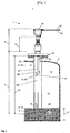
- Fig. 1 is a level gauge 1 as a time domain reflectometer or TDR Messsytem for determining the continuous level 2 of a medium 3 in the process chamber 34 of a container 6 shown.
- the level measuring device 1 is composed of a measuring active region 7, which comes into contact with the medium 3 or the superimposed gas phase of the process chamber 34 in contact with the process, and a measuring inactive region 8, separated from the process chamber 34 Probe coupling region 12 and a separate from the process space 34 transmitter 25, together.
- This level gauge 1 is attached to the container 6, for example via a flange 20 and / or a process thread 19.
- a high-frequency measuring signal HF generated in the RF unit 26 of the measuring transducer 25 is coupled into and out of the measuring probe RF located in the process chamber 34 of a container 6 via a probe coupling region 12 designed as a coaxial system.
- the waveguide 9 is constructed in this illustration as a coaxial probe 10, consisting of an outer conductor 10b and an inner conductor 10a.
- waveguides 9 such as a Sommerfeld waveguide (single-waveguide), a Goubau waveguide (single-wire waveguide with dielectric coating), a Lecher line (two-wire waveguide), a microstrip waveguide or a waveguide with arbitrary, rectangular or round cross sections usable in this method.
- the inner conductor 10a of the measuring probe 9 in Fig. 1 has a probe thickening 17 starting from the probe coupling-in area 12.
- a probe fitting 16 is incorporated, so that a corresponding probe 9 or a corresponding waveguide 9 can be screwed in the form of a rod or a rope of the intended length.
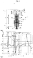
- FIG. 2 An enlarged section of the waveguide 9 and the transmitter 25 of the in Fig. 1 illustrated level gauge 1 is in Fig. 2 shown enlarged.
- the TDR measuring method works according to the following measuring principle: High-frequency measuring signals HF are emitted via the measuring probe 9 as a transmitting pulse M in the direction of the medium 3 or into the process space 34. This transmit pulse M is reflected back either as a useful echo signal N or due to a change in the geometry of the waveguide 9 as a false echo signal S either due to a DK value jump or a discontinuity of the dielectric constant of the substance surrounding the probe 9.
- a discontinuity of the characteristic impedance is present, for example, at the boundary layer 4 of the medium 3, if the dielectric constant er2 of the gas phase 5 superimposed on the medium 3, in particular in the case of air2, is smaller than the dielectric constant er1 of the medium 3.
- the level 2 of the medium 3 in the container 6 corresponds to the height of the container 6 and the location of the Coupling of the high-frequency measurement signals HF in the waveguide 9 minus the traversed simple running distance x of the high-frequency measurement signals HF. Since the height of the container 6 is known, thus the level 2 in the container 6 can be determined.
- the high-frequency measurement signals HF and the electromagnetic waves propagate at almost the speed of light, therefore resulting in very short maturities t.
- differences in the transit time t of about 10 picoseconds are to be determined.
- the measurement of these short times is possible only with the use of special electronic components and a high measurement effort. Therefore, the reflected echo curve signal E, which includes at least the useful echo signal N and the false echo signals S, is transformed into a low-frequency range as an intermediate-frequency signal, usually by means of a sequential sampling.
- This intermediate frequency signal is generated for example by the mixer principle of a transmission pulse signal and a slightly phase-shifted Abtastimpulssignal. After a subsequent digitization of the transformed into an intermediate frequency signal echo curve signal E this is further processed in a microprocessor in the control / evaluation unit 27, filtered and evaluated.
- the electromagnetic waves are generated for example as transmission pulses M with a bandwidth of 0-1.5 GHz in the RF unit 26 in the transmitter 25 and coupled by means of a probe coupling 12 at the probe 9, for example, in the coaxial probe 10.
- the useful echo signals N or false echo signals S returning due to the discontinuity of the dielectric constant of the surrounding substance are in turn received in the RF unit 26 and preferably processed as a time-expanded intermediate frequency signal as described above.
- These processed high-frequency measurement signals HF are also evaluated in the control / evaluation 27 metrological and signaling technology, for example, by these filtered, time-transformed and smoothed.
- the measured value of the fill level 2 or the echo curve E representing the entire measurement situation which represents the processed envelope from the superimposition of the transmit pulse M, the false echo signals S and the useful echo signal N, are transmitted to the fieldbus 30 via a bus interface 29 to, for example, a control center and / or other field devices forwarded.
- the measured value of the fill level 2 or the echo curve E can also be displayed on an integrated display or an output / input unit 28 of the level gauge 1 being represented.
- the energy supply of the level measuring device 1 is realized for example by means of a two-wire line.
- the additional supply line 31 for energy supply is eliminated if it is the level meter 1 is a so-called two-wire meter whose communication via the field bus 30 and supply line 31 exclusively and simultaneously via a two-wire line.
- the data transmission or communication via the fieldbus 30 is implemented, for example, according to the CAN, HART, PROFIBUS DP, PROFIBUS FMS, PROFIBUS PA, or FOUNDATION FIELDBUS standard.
- Fig. 2 shows an axial cross-sectional view of a partial section of the in Fig. 1
- the measuring probe 9 consists of a pressure-bearing, temperature-resistant probe coupling housing 18.
- This probe coupling housing 18 extends over the entire probe coupling region 12 as far as a coaxial glass feedthrough 22, at which the signal feed of the high-frequency measuring signal HF via a flexible coaxial line 24 takes place via a coaxial connector 23 of the RF unit 26.
- a coaxial glass feedthrough 22 at which the signal feed of the high-frequency measuring signal HF via a flexible coaxial line 24 takes place via a coaxial connector 23 of the RF unit 26.
- temperature-resistant filling materials 21 are used.
- temperature-resistant filling materials 21 for example, ceramics, such as alumina ceramic, in question, which not only have the advantage of higher mechanical strength compared to the glass of the glass bushing 22, but because of the much better resistance to hydrolysis ceramics can also process-touching used become.
- chemically resistant plastics as filling material 21 for the probe coupling housing 18 in the case of measuring probes 9, in particular in the low-temperature range.
- a stainless steel or, for example, Hastelloy® is preferably used due to the particular material strength, which has a bending strength of 20 to 60 Nm at the measuring probe 9 with an inner conductor diameter of only 10 mm.
- primary sealing elements 33 are used for example in the form of graphite stuffing box packings, elastomer seals and / or steel-ceramic compounds. These upstream sealing elements 33 are primarily used to protect the gas diffusion-proof glass bushing 22 and prevent the penetration of the medium 3 in the space between the inner conductor 10a or outer conductor 10b and the filling material 21 of the probe coupling 12. The penetration of medium in this area has the consequence that the measurement conditions due to changes in the propagation characteristic and propagation speed of the high-frequency measurement signals HF in this range vary and thus no accurate measurement of the level 2 can be performed.
- the choice of material and the configuration of the probe coupling region 12 of the measuring probe 9 are implemented in such a way that the characteristic impedance or the impedance of the high-frequency measuring signal HF is adapted.
- the circuitry of the RF unit 26 in the transmitter 25, as well as the coaxial line 24 are tuned to an impedance of about 50 ohms.
- the impedance of a single-rod probe 11 is well above this value, for example, results in a single-rod probe 11 with a radius of about 10 mm, a wall distance to the container 6 of one hundred millimeters and with an injection into air, an impedance of approximately 200 ohms.
- the aim is to design an impedance-matched measuring probe 9, so that the probe coupling-in region 12 and the supply of the high-frequency measuring signal HF via the coaxial line 24 to an impedance of about 50 ohms is designed and thus no multiple reflections and false echo signals S result.
- a coaxial resonator is formed in the probe coupling-in region 21. It is therefore chosen a smaller outer conductor diameter, which results in a lower impedance than 50 ohms.
- this unmatched area is deliberately chosen to be very small in its axial extent, resulting in no significant ringing in the decay behavior.
- the ringing in the echo curve E would be reflected in the fact that the echo signals in the echo curve E do not decay quickly, but lose only slowly at amplitude A.
- the ringing edge of the transmission pulse M can cover the useful echo signal N in the measuring active region 7, so that no useful useful echo signal N can be detected in the vicinity of the transition from the probe coupling region 12 to the measuring probe region 13 of the measuring probe 9.
- a coaxial probe 10 is used as a measuring probe 9
- a tubular structure is screwed onto the process thread 19 as outer conductor 10b with the probe coupling region 19 of the measuring probe 9, for example.
- the outer conductor 10b is firmly installed in the container 6 as a pipe, as in the Fig. 1 indicated, so that the inner conductor 10a of the measuring probe 9 is guided through an opening in the pipe in the process chamber 34 and the process chamber 34 is sealed to the flange 20 on the measuring probe 9.
- At the outer conductor 10b of the coaxial probe 10 there is a ventilation opening 32, so that with increasing medium 3 in the container 6 located in the space of the coaxial probe 10 gas can escape into the process chamber 34.
- the adaptation of the impedance of the measuring probe 9 as coaxial probe 10 is different from that of the single-rod probe 11.
- the impedance jump at the transition from the probe coupling region 12 to the measuring probe region 13 is smaller in this case, whereby in this case a smaller second false echo signal S2 is to be expected at this point.
- Fig. 3 and Fig. 4 the current, shifted and optimal echo curves E1, E2, E3 of the high-frequency measurement signal HF are shown proportional to the travel distance x in meters. These echo curves reflect different measurement situation of the in Fig. 1 imaged level gauge 1 again.
- the path x of the high-frequency measurement signal HF is plotted, and the ordinate axis contains the amplitude A of the high-frequency measurement signal HF in millivolts.
- Fig. 3 the current echo curve E1 are shown as a dashed line and the echo curve E2 shifted according to the invention by a path difference Dx.
- the shifted echo curve E2 has been shifted by the method according to the invention in order to adapt and calibrate the current echo curve E1 to changes in the measurement conditions or device properties.
- FIG. 3 is a measurement situation shown, in which due to leakage in the sealing elements 33, for example, water as water vapor has penetrated to the glass feedthrough 22 in the space between the inner conductor 10a and filler 21, which has increased due to the thereby reduced speed of propagation of the high-frequency measurement signals HF, the transit time t .
- the reference echo signal R of the shifted echo curve E2 is shifted to the left in contrast to the reference echo signal R of the current echo curve E1. That is also in Fig. 4 to see where the shifted echo curve E2 is compared with the optimum echo curve E3 recorded prior to the start of the measurement. Also in Fig.
- the following inventive determination method is not limited only to the current, optimal or shifted echo curve E1, E2, E3, but can be applied in all echo curve E. Therefore, in the following only the generally valid concept of the echo curves E is used.
- Starting from initial positions IP1, IP2, IP3, IP4 in the echo curve E is in the limits of the search window H with a predetermined search width SB for the transmission signal M, the useful echo signal N, the reference echo signal R and other false echo signals S searched.
- the initial positions IP, the symmetry of the search windows H and the search widths SB of the search windows H have been predefined by the user or manufacturer as empirical values or stored parameters of the initial positions IP and the search widths SB of previous measurement cycles are used.
- the search windows H can be arranged asymmetrically around the initial positions IP, for example in the case of the third false echo signal S3, the distance of which can only increase in relation to the reference point B.
- a reference echo signal R is determined for the rough determination of the reference point B.
- a reference echo signal R for example, the transmission pulse M of the high-frequency measurement signal HF generated in the RF unit 26 is used.
- the use of the transmitted pulse M as a reference echo signal R has the advantage that its time of generation can be determined quite accurately, since it has a first high amplitude A1 and a very narrow pulse width.
- the vertex of the reference echo signal R and its position in the echo curve E are determined.
- a plausibility check can additionally be carried out via the sign and / or the amplitude A.
- the reference echo signal R and / or the clutter echo signals S for example, a parabola can be fitted to the echo curve E, the vertex of this parabola then determines the location and amplitude of these echo signals.
- a first false echo signal S1 is determined.
- This first false echo signal S1 is caused by an interfering element 14 due to the geometrical change of the inner conductor 10a of the measuring probe 9 in the form of a matching element 15.
- This matching element 15 is designed such that a first spurious echo signal S 1 is generated with a second low amplitude A 2 and thus an influence on the measurement due to multiple reflections in the echo curve E is reduced.
- a fine determination of the reference point B is made.
- the matching element 15 is formed in the measuring-inactive region 8 of the measuring probe 9, so that the first false echo signal S1 can not be influenced by the medium 3, the gas phase 5, or the installation in the container 6.
- the adaptation element 15 is arranged so far in the direction of measuring-active region 7 that the first false echo signal S1 can not practically be influenced by transit time changes in the measurement-inactive region 8. For example, such transit time changes in the probe coupling region 12 are caused by penetrated medium or in the region of the coaxial line 24 due to temperature changes.
- the second false echo signal S2 which is produced by an impurity 14 at the transition between the measuring inactive area 8 and the measuring active area 7 of the measuring probe 9, is less suitable for diagnosis and calibration purposes than the first false echo signal S1, since it depends on the installation conditions and / or the to be measured medium 3 is influenced.
- the second false echo signal S2 is smaller and temporally shifted by the installation in the nozzle or on the flange 20. If the level rises at a high DK value until it reaches the transition between the area 8 that is not active in the measurement area and the measuring area 7 of the measuring probe 9, the second false echo signal S2 is also completely covered by the useful echo signal N and can no longer be determined.
- this second false echo signal S2 in the method according to the invention finds no further consideration and / or use for determining the reference point B. To determine the approach of medium 3 in this transitional region by means of a changing amplitude A, the second false echo signal S2 can be used in this determination method ,
- a third false echo signal S3 is determined, which arises at an impurity 14 in the measuring active region 7 of the measuring probe 9, such as at a cross-sectional jump through a measuring probe thickening 17 of the measuring probe 9.
- This measuring probe thickening 17th is designed so that the characteristic impedance at the end of the measuring probe thickening 17 is again only slightly reduced and thus only a third false echo signal with a small, negative amplitude A is produced, which is the Measurement due to occurring multiple reflections only insignificantly affected.
- a calibration of the propagation velocity of the high-frequency measuring signals HF on the measuring probe 9 within the gas phase 5 can be carried out, since the dimensions of the measuring probe 9 and the distances between the defects 14 predetermine or are known.
- the wanted echo signal N in the echo curve E is determined on the basis of a predetermined or determined initial position IP4. From the distance D between the reference point B and the useful echo signal N and the height of the container 6, as described above, the level 2 of the medium 3 can be calculated.
- the illustrated useful echo signal N has been generated, for example, by water as the medium 3.
- the optimal echo curve E3, in Fig. 4 shown as a dashed line was recorded at room temperature and atmospheric pressure in the process chamber 34 of the container 6.
- the shifted echo curve E2 in Fig. 4 drawn as a solid line recorded at a later time in process conditions with temperatures at about 200 degrees Celsius and at a pressure of about 16 bar.
- the shifted echo curve E2 has been shifted by the method according to the invention in order to adapt the echo curve E to the changes in the measurement conditions, for example due to medium 3 which has penetrated into the probe coupling region 12.
- the amplitude A of the false echo signal G of the glass feedthrough 22 is strongly damped, as a result of which this measuring situation can thus be easily detected.
- the shifted echo curve 2 an extension of the echo curve E due to penetrated medium is shown. This can either be compensated by a shift or calibration of the echo curves E to the reference point B or used for an error message.
- a reduced amplitude A or changed curve V of the reference echo signal R and / or the first false echo signal S1 it could be concluded, for example, that the sensitivity of the fill level measuring device 1 has decreased, for example as a result of aging of the electronics in the transmitter 25.
- the echo curves E can be stored in the memory 25 in the transmitter by means of a memory function in the electronics of the transmitter 25 as history echoes HE. This makes it possible to change the operating characteristics of the measuring probe 9 and the electronics in the transmitter 25 or the measuring conditions in the process by a direct comparison of the distances, distance D, distances K, the curve V and / or the amplitudes A of the reference echo signal R, Use echo signal N and / or the false echo signals S to make a stored at any time history echo curve HE with the current echo curve E1.
- Another statement about the measurement conditions in the process space 34 can be derived from the distance x between the reference point B or the first false echo signal S1 in FIG Derive messineducationen area 8 of the measuring probe 9 and the third false echo signal S3 in the measuring active area 7 of the measuring probe 9.
- a diagnosis or verification of the measurement of the level gauge 1 can be performed.
- a calibration is performed by scaling the distance D, individual echo signal distances, distances K and amplitudes A in the echo curve E in the measuring active area 8 and / or an error message is output, if a predetermined threshold value of the distance D, individual echo signal intervals, Distances K and / or the amplitude A is exceeded.
- a reduced amplitude A of the third false echo signal S3 could mean, for example, that the sensitivity of the fill level measuring device 1 has deteriorated as a result of a process influence, for example in the form of attachment in the neck.
- the calibration or diagnosis of the echo curves E can be done automatically or manually, the latter, for example, in the course of a recurring examination of the level gauge 1.
Claims (18)
- Procédé destiné à la détermination et la surveillance du niveau (2) d'un produit (3) dans un réservoir (9) à l'aide d'un transmetteur de niveau (1), pour lequel sont acheminés des signaux de mesure haute fréquence (HF) d'après la méthode de la réflectométrie temporelle par l'intermédiaire d'au moins une sonde de mesure (5) en direction du produit (3) et sont réfléchis et reçus sur au moins une interface (4) du produit (3) en tant que signaux d'écho utiles (N) ou sur des irrégularités en tant que signaux d'écho parasites (S), pour lequel un signal d'écho de référence (R) est formé dans une zone de mesure inactive (12) du transmetteur de niveau (1), soit à partir d'une impulsion d'émission (M) du signal de mesure haute fréquence (HF), soit à partir de l'un des signaux d'écho parasites (S), pour lequel une courbe d'écho actuelle (E1) fonction du temps de propagation (t) ou de la distance de propagation (x) est formée à partir des signaux d'écho utiles (N), du signal d'écho de référence (R) et des signaux d'écho parasites (S), pour lequel un point de référence (B) est localisé dans la courbe d'écho actuelle (E1) au moins à partir d'un premier signal d'écho parasite (S1) et du signal d'écho de référence (R), qui sont occasionnés dans une zone de mesure inactive (12) du transmetteur de niveau (1), pour lequel le niveau (2) est déterminé par rapport au point de référence (B) situé dans la courbe d'écho actuelle (E1) à partir de la distance (D) du signal d'écho utile (N) formé dans une zone de mesure active (11) du transmetteur de mesure (1).
- Procédé selon la revendication 1, pour lequel est réalisée au moyen du signal d'écho de référence (R), avec une première amplitude élevée (A1), une détermination approximative du point de référence (B).
- Procédé selon la revendication 1, pour lequel est réalisée au moyen du premier signal d'écho parasite (S1), avec une deuxième amplitude faible (A2), une détermination précise du point de référence (B).
- Procédé selon la revendication 1, 2 ou 3, pour lequel la courbe d'écho actuelle (E1) est déplacée pour la localisation du point de référence (B) en ce que le premier signal d'écho parasite (S1) de la courbe d'écho actuelle (E1) est déplacé à une position initiale (IP1) prédéfinie du premier signal d'écho parasite (S1).
- Procédé selon la revendication 4, pour lequel la position (P) et l'amplitude (A) du premier signal d'écho parasite (S1) et/ou du point de référence (B) sont enregistrées continuellement en tant que données.
- Procédé selon la revendication 4, pour lequel le déroulement temporel et les changements d'amplitude (A) du premier signal parasite (S1) ou du point de référence (B) sont déterminés et représentés à partir des données.
- Procédé selon la revendication 4, pour lequel la courbe d'écho déplacée (E2) est enregistrée de façon cyclique, commandée par événement ou manuellement en tant que courbe d'écho historique (HE).
- Procédé selon la revendication 7, pour lequel la courbe d'écho déplacée (E2) est représentée conjointement avec la courbe d'écho historique (HE) enregistrée.
- Procédé selon la revendication 1, 2, 3 ou 4, pour lequel un diagnostic de fonctionnement du transmetteur de niveau (1) est exécuté au moyen de la détermination de la distance (D) et/ou de l'allure de la courbe (K) du signal d'écho de référence (R) et du premier signal d'écho parasite (S1) dans la courbe d'écho actuelle (E1) et/ou dans la courbe d'écho déplacée (E2).
- Procédé selon la revendication 1 ou 4, pour lequel au moins un troisième signal d'écho parasite (S3) est déterminé dans une zone de mesure active (11) du transmetteur de niveau (1) dans la courbe d'écho actuelle (E1) et/ou dans la courbe d'écho déplacée (E2).
- Procédé selon la revendication 10, pour lequel un étalonnage de la vitesse de propagation des signaux de mesure haute fréquence (HF) est effectué dans la phase gazeuse (8) au-dessus du niveau (2) du produit (3) sur la base de l'allure de la courbe (K) entre le troisième signal d'écho parasite (S3) et le point de référence (B).
- Procédé selon la revendication 11, pour lequel le niveau (2) déterminé est corrigé sur la base de la vitesse de propagation étalonnée des signaux de mesure haute fréquence (HF) dans la phase gazeuse (8).
- Procédé selon la revendication 1 à 6 ou 9 à 12, pour lequel les signaux d'écho parasites (S), le signal d'écho de référence (R) et/ou les signaux d'écho utiles (N) sont déterminés sur la base d'au moins une étape de recherche (K) dans au moins une fenêtre de recherche (H) prédéfinie dans la courbe d'écho actuelle (E1).
- Procédé selon la revendication 13, pour lequel le grand signal d'écho de référence est déterminé dans une première étape de recherche (K1) dans la première fenêtre de recherche (H1) de la courbe d'écho actuelle (E1), le premier signal d'écho de référence (S1) dans une deuxième étape de recherche (K2) dans la deuxième fenêtre de recherche (H2) de la courbe d'écho actuelle (E1), le troisième signal d'écho de référence (S3) dans une troisième étape de recherche (K3) dans la troisième fenêtre de recherche (H3) de la courbe d'écho actuelle (E1) et/ou le signal d'écho parasite (N) dans une quatrième étape de recherche (K4) dans la quatrième fenêtre de recherche (H4) de la courbe d'écho actuelle (E1).
- Procédé selon la revendication 13 à 14, pour lequel les étapes de recherche (K) sont exécutées simultanément dans les fenêtres de recherche (H) prédéfinies de la courbe d'écho actuelle (E1) en vue de la détermination des signaux d'écho parasites (S), des signaux d'écho de référence (R) et/ou des signaux d'écho utiles (N).
- Procédé selon la revendication 13 à 15, pour lequel les fenêtres de recherche (H1, H2, H3, H4) d'une largeur de recherche (SB) prédéfinie et dans une disposition symétrique ou asymétrique prédéfinie, sont générées autour d'une position initiale (IP1, IP2, IP3, IP4).
- Procédé selon la revendication 4, 9 ou 11, pour lequel la localisation de la position de référence (B), l'étalonnage de la vitesse de propagation et/ou le diagnostic de fonctionnement du transmetteur de niveau (1) sont démarrés manuellement par l'opérateur.
- Procédé selon la revendication 4, 9 ou 11, pour lequel la localisation de la position de référence (B), l'étalonnage de la vitesse de propagation et/ou le diagnostic de fonctionnement du transmetteur de niveau (1) sont démarrés automatiquement selon des cycles prédéfinis ou de façon commandée par événement.
Applications Claiming Priority (2)
| Application Number | Priority Date | Filing Date | Title |
|---|---|---|---|
| DE102006019191A DE102006019191A1 (de) | 2006-04-21 | 2006-04-21 | Verfahren zur Ermittlung und Überwachung des Füllstands eines Mediums in einem Behälter |
| PCT/EP2007/053599 WO2007122116A1 (fr) | 2006-04-21 | 2007-04-13 | Procédé pour déterminer et surveiller le niveau de remplissage d'un fluide dans un récipient |
Publications (2)
| Publication Number | Publication Date |
|---|---|
| EP2010871A1 EP2010871A1 (fr) | 2009-01-07 |
| EP2010871B1 true EP2010871B1 (fr) | 2016-04-13 |
Family
ID=38219499
Family Applications (1)
| Application Number | Title | Priority Date | Filing Date |
|---|---|---|---|
| EP07728066.7A Active EP2010871B1 (fr) | 2006-04-21 | 2007-04-13 | Procédé pour déterminer et surveiller le niveau de remplissage d'un fluide dans un récipient |
Country Status (5)
| Country | Link |
|---|---|
| US (1) | US7965087B2 (fr) |
| EP (1) | EP2010871B1 (fr) |
| CA (1) | CA2649466C (fr) |
| DE (1) | DE102006019191A1 (fr) |
| WO (1) | WO2007122116A1 (fr) |
Families Citing this family (35)
| Publication number | Priority date | Publication date | Assignee | Title |
|---|---|---|---|---|
| DE102005044724A1 (de) * | 2005-09-19 | 2007-03-22 | Endress + Hauser Gmbh + Co. Kg | Laufzeitmessverfahren zur Ermittlung der Distanz |
| US7924216B2 (en) * | 2008-04-30 | 2011-04-12 | Rosemount Tank Radar Ab | Method of determining a disturbance echo profile for a radar level gauge system |
| DE102009001010B4 (de) * | 2008-12-30 | 2023-06-15 | Endress+Hauser SE+Co. KG | Verfahren zur Ermittlung und Überwachung des Füllstands eines Mediums in einem Behälter nach einem Laufzeitmessverfahren |
| DE102009011278B4 (de) * | 2009-03-05 | 2017-04-20 | Imko Micromodultechnik Gmbh | Sonde sowie Vorrichtung zur Ermittlung der Materialfeuchte oder Leitfähigkeit eines Mediums |
| DE102009045180A1 (de) | 2009-09-30 | 2011-03-31 | Ifm Electronic Gmbh | Füllstandssensor mit geführter Mikrowelle für zwei unterschiedliche Sondentypen |
| DE102009055262A1 (de) * | 2009-12-23 | 2011-06-30 | Endress + Hauser GmbH + Co. KG, 79689 | Verfahren zur Ermittlung und Überwachung des Füllstands eines Mediums in einem Behälter nach einem Laufzeitmessverfahren |
| US20120137767A1 (en) * | 2010-12-06 | 2012-06-07 | Atek Products, Llc | Time domain reflectometry device and method |
| WO2012079642A1 (fr) | 2010-12-16 | 2012-06-21 | Vega Grieshaber Kg | Dispositif de mesure, dispositif de commande et appareil de mesure pour la mesure d'un niveau |
| US8813559B2 (en) | 2010-12-16 | 2014-08-26 | Vega Grieshaber Kg | Determination of media characteristics in fill-level measuring |
| CA2826049C (fr) | 2010-12-16 | 2016-09-06 | Vega Grieshaber Kg | Determination de proprietes de fluide lors de la mesure d'un niveau de remplissage |
| DE102011007372B4 (de) * | 2011-04-14 | 2023-05-04 | Endress+Hauser SE+Co. KG | Kalibrations- und/oder Überwachungsverfahren für FMCW-Radar Füllstandsmessgeräte |
| EP2527805B1 (fr) | 2011-05-27 | 2022-11-30 | VEGA Grieshaber KG | Dispositif d'évaluation et procédé de détermination d'une grandeur caractéristique pour la position d'une surface limite dans un récipient |
| EP2527804B1 (fr) | 2011-05-27 | 2020-04-29 | VEGA Grieshaber KG | Procédé de reconnaissance d'échos multiples et d'échos de sol |
| DE102012101725A1 (de) * | 2012-03-01 | 2013-09-05 | Sick Ag | Verfahren zur Füllstandsmessung |
| DE102012105281A1 (de) * | 2012-06-18 | 2013-12-19 | Endress + Hauser Gmbh + Co. Kg | Füllstandsmessgerät und Vorrichtung zur Bestimmung der Dielektrizitätszahl |
| DE102012014267B4 (de) * | 2012-07-19 | 2020-12-24 | Krohne S.A. | Nach dem Radar-Prinzip arbeitendes Füllstandmessgerät |
| US9228877B2 (en) * | 2012-09-26 | 2016-01-05 | Rosemount Tank Radar Ab | Guided wave radar level gauge system with dielectric constant compensation through multi-frequency propagation |
| US10927664B2 (en) | 2013-06-14 | 2021-02-23 | Welldata (Subsurface Surveillance Systems) Ltd | Downhole detection |
| DE102013107847A1 (de) | 2013-07-23 | 2015-01-29 | Endress + Hauser Gmbh + Co. Kg | Verfahren zur Ermittlung und Überwachung des Füllstands eines Mediums in einem Behälter nach einem Laufzeitmessverfahren |
| EP3074733A1 (fr) * | 2013-11-27 | 2016-10-05 | VEGA Grieshaber KG | Sonde coaxiale à conducteur intérieur serré |
| US9541444B2 (en) | 2014-04-01 | 2017-01-10 | Rosemount Tank Radar Ab | Self-diagnosing FMCW radar level gauge |
| WO2015171820A1 (fr) | 2014-05-08 | 2015-11-12 | WellGauge, Inc. | Surveillance de profondeur d'eau de puits |
| DE102014112453A1 (de) * | 2014-08-29 | 2016-03-03 | Endress + Hauser Gmbh + Co. Kg | Radarfüllstandmessgerät |
| US9921096B2 (en) * | 2014-09-10 | 2018-03-20 | Honeywell International Inc. | Mechanical system for centering and holding a coax conductor in the center of an outer conductor |
| US10180342B2 (en) * | 2014-10-01 | 2019-01-15 | Honeywell International Inc. | Level finding using multiple search steps |
| DE102014114752A1 (de) * | 2014-10-10 | 2016-04-14 | Krohne S. A. S. | Verfahren sowie Vorrichtung zur Füllstandsmessung |
| GB201420938D0 (en) * | 2014-11-25 | 2015-01-07 | Welldata Subsurface Surveillance Systems Ltd | Monitoring structures |
| EP3067711B1 (fr) * | 2015-03-13 | 2019-12-18 | Honeywell International Inc. | Appareil et procédé de réglage de largeur d'impulsion radar à ondes guidées pour optimiser des mesures |
| EP3173750B1 (fr) * | 2015-11-26 | 2019-10-16 | VEGA Grieshaber KG | Appareil de mesure du niveau de remplissage et procédé de mesure d'un niveau de remplissage |
| DE102015122284A1 (de) * | 2015-12-18 | 2017-06-22 | Endress + Hauser Gmbh + Co. Kg | Elektronikeinheit mit Diagnosefunktion |
| DE102016108665B4 (de) | 2016-05-11 | 2020-09-17 | Krohne S. A. S. | Verfahren zur Überwachung eines nach dem Radarprinzip arbeitenden Füllstandmessgeräts und Füllstandmessgerät |
| DE102016124982A1 (de) * | 2016-12-20 | 2018-06-21 | Endress+Hauser SE+Co. KG | Temperaturbeständiges Füllstandsmessgerät |
| US10760941B2 (en) | 2017-04-21 | 2020-09-01 | Magnetrol International, Incorporated | Steam probe with condensation return |
| DE102017109316A1 (de) * | 2017-05-02 | 2018-11-08 | Endress+Hauser SE+Co. KG | Verfahren zur Bestimmung und/oder Überwachung des Füllstands |
| DE102017119502A1 (de) * | 2017-08-25 | 2019-02-28 | Krohne S. A. S. | TDR-Füllstandmessgerät und Verfahren zum Betreiben eines TDR-Füllstandmessgeräts |
Family Cites Families (8)
| Publication number | Priority date | Publication date | Assignee | Title |
|---|---|---|---|---|
| GB2164151B (en) | 1984-09-07 | 1988-12-21 | James Gerald Lacy | Measuring apparatus |
| GB2260235B (en) | 1991-09-26 | 1995-07-12 | Schlumberger Ind Ltd | Measurement of liquid level |
| GB9211086D0 (en) * | 1992-05-23 | 1992-07-15 | Cambridge Consultants | Short range electromagnetic sensing signal processing |
| DE4241910C2 (de) * | 1992-12-11 | 1996-08-01 | Endress Hauser Gmbh Co | Mit Mikrowellen arbeitendes Füllstandsmeßgerät |
| US6559657B1 (en) | 1999-01-13 | 2003-05-06 | Endress+Hauser Gmbh+Co. | Probe mapping diagnostic methods |
| US6679115B2 (en) * | 2001-02-14 | 2004-01-20 | Endress + Hauser Gmbh + Co. | Apparatus for determining the filling level of a product in a container |
| DE10160688A1 (de) * | 2001-12-11 | 2003-06-18 | Endress & Hauser Gmbh & Co Kg | Vorrichtung zur Bestimmung und/oder Überwachung des Füllstandes eines Füllguts in einem Behälter |
| US6867729B2 (en) | 2003-07-30 | 2005-03-15 | Magnetrol International | Guided wave radar level transmitter with automatic velocity compensation |
-
2006
- 2006-04-21 DE DE102006019191A patent/DE102006019191A1/de not_active Withdrawn
-
2007
- 2007-04-13 EP EP07728066.7A patent/EP2010871B1/fr active Active
- 2007-04-13 US US12/226,432 patent/US7965087B2/en active Active
- 2007-04-13 WO PCT/EP2007/053599 patent/WO2007122116A1/fr active Application Filing
- 2007-04-13 CA CA2649466A patent/CA2649466C/fr active Active
Also Published As
| Publication number | Publication date |
|---|---|
| US20090302867A1 (en) | 2009-12-10 |
| US7965087B2 (en) | 2011-06-21 |
| DE102006019191A1 (de) | 2007-10-25 |
| WO2007122116A1 (fr) | 2007-11-01 |
| CA2649466C (fr) | 2013-06-11 |
| CA2649466A1 (fr) | 2007-11-01 |
| EP2010871A1 (fr) | 2009-01-07 |
Similar Documents
| Publication | Publication Date | Title |
|---|---|---|
| EP2010871B1 (fr) | Procédé pour déterminer et surveiller le niveau de remplissage d'un fluide dans un récipient | |
| DE102007060579B4 (de) | Verfahren zur Ermittlung und/oder zur Beurteilung des Befüllzustands eines mit zumindest einem Medium gefüllten Behälters | |
| EP2652462B1 (fr) | Dispositif de mesure, dispositif de commande et appareil de mesure pour la mesure d'un niveau | |
| EP2154495B1 (fr) | Capteur TDR et procédé de mesure | |
| EP1412710B1 (fr) | Procede pour evaluer les signaux de mesure d'un appareil de mesure fonctionnant selon le principe du temps de propagation | |
| DE102005042646A1 (de) | Vorrichtung zur Ermittlung und Überwachung des Füllstandes eines Mediums in einem Behälter | |
| EP2634541B1 (fr) | Procédé de mesure de niveau de remplissage | |
| DE10297390B4 (de) | Materialkonzentrationsmessung in einem Prozeßfluid | |
| DE102010038732B4 (de) | Vorrichtung und Verfahren zur Sicherung der Befestigung eines koaxial um eine Messsonde angeordneten Rohres einer Messsondeneinheit eines Füllstandsmessgerätes an einem Prozessanschlusselement | |
| EP2365302B1 (fr) | Mesure de la distance par rapport à, au moins, une première surface limite | |
| DE202008018156U1 (de) | Sensor nach dem TDR-Prinzip mit einer koaxialen Sonde | |
| EP2652465B1 (fr) | Détermination de propriétés de fluide lors de la mesure d'un niveau de remplissage | |
| DE102010042525A1 (de) | Verfahren zur Ermittlung und Überwachung des Füllstands eines Mediums in einem Behälter mittels eines Füllstandsmessgeräts nach einem Laufzeitmessverfahren | |
| DE102019110256A1 (de) | TDR-Messvorrichtung zur Bestimmung der Dielektrizitätskonstanten | |
| EP1191315A2 (fr) | Dispositif et procédé pour la détermination de la position de l'interface entre deux milieux distincts | |
| EP1128169A1 (fr) | Méthode et dispositif pour la détermination du niveau limite d'un produit dans un récipient | |
| WO2022058101A1 (fr) | Étalonnage de jauges modulaires de niveau de remplissage | |
| DE102016105419B4 (de) | Verfahren zur Bestimmung eines Rohr-Innendurchmessers eines Schwallrohres durch ein Füllstandsmessgerät | |
| EP3837509B1 (fr) | Dispositif de mesure de niveau de remplissage | |
| DE102017123529A1 (de) | Verfahren zur Ermittlung des Füllstandes eines in einem Behälter befindlichen Füllgutes | |
| DE202013101738U1 (de) | Füllstandssensor zur Bestimmung eines Füllstands nach dem TDR-Prinzip | |
| EP2652463A1 (fr) | Dispositif pour la mesure d'une émulsion comportant un tube vertical | |
| DE102020121151A1 (de) | Temperaturkompensiertes Dielektrizitätswert-Messgerät | |
| DE102020134061A1 (de) | Hochfrequenz-basiertes Feldgerät |
Legal Events
| Date | Code | Title | Description |
|---|---|---|---|
| PUAI | Public reference made under article 153(3) epc to a published international application that has entered the european phase |
Free format text: ORIGINAL CODE: 0009012 |
|
| 17P | Request for examination filed |
Effective date: 20081014 |
|
| AK | Designated contracting states |
Kind code of ref document: A1 Designated state(s): AT BE BG CH CY CZ DE DK EE ES FI FR GB GR HU IE IS IT LI LT LU LV MC MT NL PL PT RO SE SI SK TR |
|
| AX | Request for extension of the european patent |
Extension state: AL BA HR MK RS |
|
| RIN1 | Information on inventor provided before grant (corrected) |
Inventor name: REIMELT, RALF Inventor name: SCHROTH, HERBERT |
|
| DAX | Request for extension of the european patent (deleted) | ||
| GRAP | Despatch of communication of intention to grant a patent |
Free format text: ORIGINAL CODE: EPIDOSNIGR1 |
|
| INTG | Intention to grant announced |
Effective date: 20151110 |
|
| GRAS | Grant fee paid |
Free format text: ORIGINAL CODE: EPIDOSNIGR3 |
|
| GRAA | (expected) grant |
Free format text: ORIGINAL CODE: 0009210 |
|
| AK | Designated contracting states |
Kind code of ref document: B1 Designated state(s): AT BE BG CH CY CZ DE DK EE ES FI FR GB GR HU IE IS IT LI LT LU LV MC MT NL PL PT RO SE SI SK TR |
|
| REG | Reference to a national code |
Ref country code: GB Ref legal event code: FG4D Free format text: NOT ENGLISH |
|
| REG | Reference to a national code |
Ref country code: AT Ref legal event code: REF Ref document number: 790630 Country of ref document: AT Kind code of ref document: T Effective date: 20160415 Ref country code: CH Ref legal event code: EP |
|
| REG | Reference to a national code |
Ref country code: FR Ref legal event code: PLFP Year of fee payment: 10 |
|
| REG | Reference to a national code |
Ref country code: IE Ref legal event code: FG4D Free format text: LANGUAGE OF EP DOCUMENT: GERMAN |
|
| REG | Reference to a national code |
Ref country code: DE Ref legal event code: R096 Ref document number: 502007014713 Country of ref document: DE |
|
| REG | Reference to a national code |
Ref country code: LT Ref legal event code: MG4D |
|
| PG25 | Lapsed in a contracting state [announced via postgrant information from national office to epo] |
Ref country code: BE Free format text: LAPSE BECAUSE OF NON-PAYMENT OF DUE FEES Effective date: 20160430 |
|
| REG | Reference to a national code |
Ref country code: NL Ref legal event code: MP Effective date: 20160413 |
|
| PG25 | Lapsed in a contracting state [announced via postgrant information from national office to epo] |
Ref country code: FI Free format text: LAPSE BECAUSE OF FAILURE TO SUBMIT A TRANSLATION OF THE DESCRIPTION OR TO PAY THE FEE WITHIN THE PRESCRIBED TIME-LIMIT Effective date: 20160413 Ref country code: LT Free format text: LAPSE BECAUSE OF FAILURE TO SUBMIT A TRANSLATION OF THE DESCRIPTION OR TO PAY THE FEE WITHIN THE PRESCRIBED TIME-LIMIT Effective date: 20160413 Ref country code: PL Free format text: LAPSE BECAUSE OF FAILURE TO SUBMIT A TRANSLATION OF THE DESCRIPTION OR TO PAY THE FEE WITHIN THE PRESCRIBED TIME-LIMIT Effective date: 20160413 Ref country code: NL Free format text: LAPSE BECAUSE OF FAILURE TO SUBMIT A TRANSLATION OF THE DESCRIPTION OR TO PAY THE FEE WITHIN THE PRESCRIBED TIME-LIMIT Effective date: 20160413 |
|
| PG25 | Lapsed in a contracting state [announced via postgrant information from national office to epo] |
Ref country code: ES Free format text: LAPSE BECAUSE OF FAILURE TO SUBMIT A TRANSLATION OF THE DESCRIPTION OR TO PAY THE FEE WITHIN THE PRESCRIBED TIME-LIMIT Effective date: 20160413 Ref country code: SE Free format text: LAPSE BECAUSE OF FAILURE TO SUBMIT A TRANSLATION OF THE DESCRIPTION OR TO PAY THE FEE WITHIN THE PRESCRIBED TIME-LIMIT Effective date: 20160413 Ref country code: GR Free format text: LAPSE BECAUSE OF FAILURE TO SUBMIT A TRANSLATION OF THE DESCRIPTION OR TO PAY THE FEE WITHIN THE PRESCRIBED TIME-LIMIT Effective date: 20160714 Ref country code: PT Free format text: LAPSE BECAUSE OF FAILURE TO SUBMIT A TRANSLATION OF THE DESCRIPTION OR TO PAY THE FEE WITHIN THE PRESCRIBED TIME-LIMIT Effective date: 20160816 Ref country code: LV Free format text: LAPSE BECAUSE OF FAILURE TO SUBMIT A TRANSLATION OF THE DESCRIPTION OR TO PAY THE FEE WITHIN THE PRESCRIBED TIME-LIMIT Effective date: 20160413 |
|
| REG | Reference to a national code |
Ref country code: CH Ref legal event code: PL |
|
| REG | Reference to a national code |
Ref country code: DE Ref legal event code: R097 Ref document number: 502007014713 Country of ref document: DE |
|
| REG | Reference to a national code |
Ref country code: IE Ref legal event code: MM4A |
|
| PG25 | Lapsed in a contracting state [announced via postgrant information from national office to epo] |
Ref country code: LI Free format text: LAPSE BECAUSE OF NON-PAYMENT OF DUE FEES Effective date: 20160430 Ref country code: DK Free format text: LAPSE BECAUSE OF FAILURE TO SUBMIT A TRANSLATION OF THE DESCRIPTION OR TO PAY THE FEE WITHIN THE PRESCRIBED TIME-LIMIT Effective date: 20160413 Ref country code: SK Free format text: LAPSE BECAUSE OF FAILURE TO SUBMIT A TRANSLATION OF THE DESCRIPTION OR TO PAY THE FEE WITHIN THE PRESCRIBED TIME-LIMIT Effective date: 20160413 Ref country code: CZ Free format text: LAPSE BECAUSE OF FAILURE TO SUBMIT A TRANSLATION OF THE DESCRIPTION OR TO PAY THE FEE WITHIN THE PRESCRIBED TIME-LIMIT Effective date: 20160413 Ref country code: RO Free format text: LAPSE BECAUSE OF FAILURE TO SUBMIT A TRANSLATION OF THE DESCRIPTION OR TO PAY THE FEE WITHIN THE PRESCRIBED TIME-LIMIT Effective date: 20160413 Ref country code: EE Free format text: LAPSE BECAUSE OF FAILURE TO SUBMIT A TRANSLATION OF THE DESCRIPTION OR TO PAY THE FEE WITHIN THE PRESCRIBED TIME-LIMIT Effective date: 20160413 Ref country code: CH Free format text: LAPSE BECAUSE OF NON-PAYMENT OF DUE FEES Effective date: 20160430 |
|
| PLBE | No opposition filed within time limit |
Free format text: ORIGINAL CODE: 0009261 |
|
| STAA | Information on the status of an ep patent application or granted ep patent |
Free format text: STATUS: NO OPPOSITION FILED WITHIN TIME LIMIT |
|
| 26N | No opposition filed |
Effective date: 20170116 |
|
| REG | Reference to a national code |
Ref country code: FR Ref legal event code: PLFP Year of fee payment: 11 |
|
| PG25 | Lapsed in a contracting state [announced via postgrant information from national office to epo] |
Ref country code: SI Free format text: LAPSE BECAUSE OF FAILURE TO SUBMIT A TRANSLATION OF THE DESCRIPTION OR TO PAY THE FEE WITHIN THE PRESCRIBED TIME-LIMIT Effective date: 20160413 Ref country code: IE Free format text: LAPSE BECAUSE OF NON-PAYMENT OF DUE FEES Effective date: 20160413 |
|
| REG | Reference to a national code |
Ref country code: AT Ref legal event code: MM01 Ref document number: 790630 Country of ref document: AT Kind code of ref document: T Effective date: 20160413 |
|
| PG25 | Lapsed in a contracting state [announced via postgrant information from national office to epo] |
Ref country code: AT Free format text: LAPSE BECAUSE OF NON-PAYMENT OF DUE FEES Effective date: 20160413 |
|
| PG25 | Lapsed in a contracting state [announced via postgrant information from national office to epo] |
Ref country code: MC Free format text: LAPSE BECAUSE OF FAILURE TO SUBMIT A TRANSLATION OF THE DESCRIPTION OR TO PAY THE FEE WITHIN THE PRESCRIBED TIME-LIMIT Effective date: 20160413 |
|
| REG | Reference to a national code |
Ref country code: DE Ref legal event code: R081 Ref document number: 502007014713 Country of ref document: DE Owner name: ENDRESS+HAUSER SE+CO. KG, DE Free format text: FORMER OWNER: ENDRESS + HAUSER GMBH + CO. KG, 79689 MAULBURG, DE |
|
| REG | Reference to a national code |
Ref country code: FR Ref legal event code: PLFP Year of fee payment: 12 |
|
| PG25 | Lapsed in a contracting state [announced via postgrant information from national office to epo] |
Ref country code: HU Free format text: LAPSE BECAUSE OF FAILURE TO SUBMIT A TRANSLATION OF THE DESCRIPTION OR TO PAY THE FEE WITHIN THE PRESCRIBED TIME-LIMIT; INVALID AB INITIO Effective date: 20070413 Ref country code: CY Free format text: LAPSE BECAUSE OF FAILURE TO SUBMIT A TRANSLATION OF THE DESCRIPTION OR TO PAY THE FEE WITHIN THE PRESCRIBED TIME-LIMIT Effective date: 20160413 |
|
| PG25 | Lapsed in a contracting state [announced via postgrant information from national office to epo] |
Ref country code: IS Free format text: LAPSE BECAUSE OF FAILURE TO SUBMIT A TRANSLATION OF THE DESCRIPTION OR TO PAY THE FEE WITHIN THE PRESCRIBED TIME-LIMIT Effective date: 20160413 Ref country code: MT Free format text: LAPSE BECAUSE OF FAILURE TO SUBMIT A TRANSLATION OF THE DESCRIPTION OR TO PAY THE FEE WITHIN THE PRESCRIBED TIME-LIMIT Effective date: 20160413 Ref country code: TR Free format text: LAPSE BECAUSE OF FAILURE TO SUBMIT A TRANSLATION OF THE DESCRIPTION OR TO PAY THE FEE WITHIN THE PRESCRIBED TIME-LIMIT Effective date: 20160413 Ref country code: LU Free format text: LAPSE BECAUSE OF NON-PAYMENT OF DUE FEES Effective date: 20160413 |
|
| PG25 | Lapsed in a contracting state [announced via postgrant information from national office to epo] |
Ref country code: BG Free format text: LAPSE BECAUSE OF FAILURE TO SUBMIT A TRANSLATION OF THE DESCRIPTION OR TO PAY THE FEE WITHIN THE PRESCRIBED TIME-LIMIT Effective date: 20160413 |
|
| PGFP | Annual fee paid to national office [announced via postgrant information from national office to epo] |
Ref country code: GB Payment date: 20220425 Year of fee payment: 16 Ref country code: FR Payment date: 20220421 Year of fee payment: 16 |
|
| P01 | Opt-out of the competence of the unified patent court (upc) registered |
Effective date: 20230601 |
|
| PGFP | Annual fee paid to national office [announced via postgrant information from national office to epo] |
Ref country code: IT Payment date: 20230426 Year of fee payment: 17 Ref country code: DE Payment date: 20230420 Year of fee payment: 17 |
|
| GBPC | Gb: european patent ceased through non-payment of renewal fee |
Effective date: 20230413 |
|
| PG25 | Lapsed in a contracting state [announced via postgrant information from national office to epo] |
Ref country code: GB Free format text: LAPSE BECAUSE OF NON-PAYMENT OF DUE FEES Effective date: 20230413 |
|
| PG25 | Lapsed in a contracting state [announced via postgrant information from national office to epo] |
Ref country code: GB Free format text: LAPSE BECAUSE OF NON-PAYMENT OF DUE FEES Effective date: 20230413 Ref country code: FR Free format text: LAPSE BECAUSE OF NON-PAYMENT OF DUE FEES Effective date: 20230430 |