EP2010733B1 - Connection system for a mobile floor - Google Patents
Connection system for a mobile floor Download PDFInfo
- Publication number
- EP2010733B1 EP2010733B1 EP07726958.7A EP07726958A EP2010733B1 EP 2010733 B1 EP2010733 B1 EP 2010733B1 EP 07726958 A EP07726958 A EP 07726958A EP 2010733 B1 EP2010733 B1 EP 2010733B1
- Authority
- EP
- European Patent Office
- Prior art keywords
- piece
- groove
- connection system
- web
- tongue
- Prior art date
- Legal status (The legal status is an assumption and is not a legal conclusion. Google has not performed a legal analysis and makes no representation as to the accuracy of the status listed.)
- Active
Links
Images


Classifications
-
- E—FIXED CONSTRUCTIONS
- E04—BUILDING
- E04F—FINISHING WORK ON BUILDINGS, e.g. STAIRS, FLOORS
- E04F15/00—Flooring
- E04F15/02—Flooring or floor layers composed of a number of similar elements
-
- E—FIXED CONSTRUCTIONS
- E04—BUILDING
- E04F—FINISHING WORK ON BUILDINGS, e.g. STAIRS, FLOORS
- E04F2201/00—Joining sheets or plates or panels
- E04F2201/01—Joining sheets, plates or panels with edges in abutting relationship
- E04F2201/0107—Joining sheets, plates or panels with edges in abutting relationship by moving the sheets, plates or panels substantially in their own plane, perpendicular to the abutting edges
- E04F2201/0115—Joining sheets, plates or panels with edges in abutting relationship by moving the sheets, plates or panels substantially in their own plane, perpendicular to the abutting edges with snap action of the edge connectors
-
- E—FIXED CONSTRUCTIONS
- E04—BUILDING
- E04F—FINISHING WORK ON BUILDINGS, e.g. STAIRS, FLOORS
- E04F2201/00—Joining sheets or plates or panels
- E04F2201/04—Other details of tongues or grooves
- E04F2201/044—Other details of tongues or grooves with tongues or grooves comprising elements which are not manufactured in one piece with the sheets, plates or panels but which are permanently fixedly connected to the sheets, plates or panels, e.g. at the factory
- E04F2201/046—Other details of tongues or grooves with tongues or grooves comprising elements which are not manufactured in one piece with the sheets, plates or panels but which are permanently fixedly connected to the sheets, plates or panels, e.g. at the factory wherein the elements are made of metal
-
- E—FIXED CONSTRUCTIONS
- E04—BUILDING
- E04F—FINISHING WORK ON BUILDINGS, e.g. STAIRS, FLOORS
- E04F2201/00—Joining sheets or plates or panels
- E04F2201/05—Separate connectors or inserts, e.g. pegs, pins, keys or strips
Definitions
- the invention relates to a connection system for a mobile floor with a plurality of rectangular in plan view plates, which are connectable at their longitudinal edges with adjacent plates, wherein the plates form a common surface and for connecting two longitudinally adjacent plates in each case a Nut scientific and a spring piece in the longitudinal edges of the adjacent plates are arranged and the groove piece and the spring piece made of a dimensionally stable material.
- the WO 01/98604 shows a floor covering with individual plates, which are detachably connected together on their longitudinal sides via a locking system.
- connection system for floors in which two adjacent plates are pivotable into one another along their longitudinal edges, so that they are held in a substantially horizontal position adjacent each other in a form-fitting manner.
- connection systems There are a number of such connection systems and these can both be machined from the material of the plate or formed by metallic elements.
- a disadvantage of the aforementioned systems is that they can be assembled and disassembled only with considerable time and thus also cost.
- Object of the present invention is therefore to provide a connection system for mobile floors, which is easy to install.
- the groove piece has a web surrounded by the plate material, a groove adjoining the latter, the opening of which narrows from its closed side to the open side, and a tongue adjoining the lower edge of the groove and the spring piece surrounded by the plate material Web, an obliquely upward away from the web spring on, and has a rail which protrudes from the rear region of the spring upwards.
- the tongue of the Nut Fus a trough and the spring on its underside a bulge, which engage in a form-fitting manner, so that a joint is formed.
- a special simple and, in cooperation with the obliquely upwardly extending spring, secure locking of the Nut comunics causes the spring piece.
- the web of the Nutcommuns and / or the web of the spring piece are glued in the longitudinal edges of the plates.
- the adhesive along the groove and / or spring bars are preferably one or more grooves in the web of Nutcommuns and / or in the web of the spring piece, which are preferably parallel to the longitudinal edge of the bottom plate.
- the longitudinal edges of the plates are supported in a face-side notching of the plates by a relining of the plate surface material with the groove piece or the spring piece. This prevents the breaking off of a cover layer, in particular of the particularly stressed panel corners.
- the end faces of adjacent plates are connected to each other by a first plate fixed to and protruding from the web, from the protruding piece of a pin protrudes upwards, which engages in a receptacle of the adjacent plate to form a positive end-side connection between to make the plates.
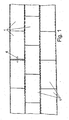
- a bottom is formed by a plurality of adjacently arranged plates 1, each at opposite longitudinal edges and opposite end edges are connected.
- the plates arranged at the edge can either be surrounded by a frame towards the outside or have a corresponding termination, since there no connection to an adjacent plate has to be made.
- connection system at the longitudinal edges is in the FIGS. 2 to 4 shown in section.
- a metal, in particular aluminum existing groove piece 2 is arranged, which engages with a web 21 in the plate 1 and is glued there.
- this groove piece engages in the opposite plate 1 made of metal, in particular aluminum, existing spring piece 3, wherein the spring piece 3 engages with a web 31 in the plate 1 and is glued there.
- the plates 1 lie next to one another in a horizontal plane and form a surface.
- the connection system is not visible from the outside and the spring piece 3 engages in the groove piece 2 a.
- the groove piece 2 has, in addition to the web 21, a groove 22 adjoining it, the opening of which narrows from its closed side to the open side. At the bottom of the groove, a tongue 23 connects, which has a rounded trough 24.
- the spring piece has, in addition to the above-mentioned web 31, a spring 32 running obliquely upward away from the web 31, which engages behind the groove 22 narrowing from its closed side toward the open side. At the rear lower side of the spring 32, a bulge 34 is formed, which engages with the trough 24 of the Nut Publisheds 2 form-fitting manner.
- groove 2 and spring piece 3 Due to the geometry of groove 2 and spring piece 3, the groove 2 and spring piece 3 are separable from each other in a very favorable for the construction and dismantling angle range of 5 ° to 25 ° and yet provide in the assembled state a secure cohesion against pulling in horizontal direction. In a special embodiment, these are even in an angular range of 10 ° to 20 ° separable from each other.
- the longitudinal edges of the plates 1 are supported in a face-side notching of the plates by a relining of the plate surface material with the groove piece 2 and the spring piece 3. As a result, in particular the corner regions of the plates are protected against breakage. From the rear region of the spring, a rail 33 protrudes upward, which forms a stable stop together with an end edge of an upper groove leg.
- the webs of tongue and groove are provided with grooves 25, 35 to ensure a uniform distribution of an adhesive along the webs.
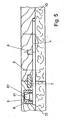
- FIG. 5 the connection of two end edges of adjacent plates 1 is shown.
- an existing metal web 4 is fixed, which protrudes beyond the front edge of the plate 1.
- an upward-facing mandrel 5 having a frusto-conical portion 51 is formed in the upper portion thereof.
- the mandrel 5 is arranged in a receptacle 6, which is formed from a hood-shaped plastic part, which is enclosed by means of teeth in the material of the plate.
- the receptacle is covered by a cover layer 61. The formation of a gap between the end edges of adjacent plates is prevented by the positive retention of the dome 5 in the receptacle 6.
- a spring 7 which is inserted in equal shares in a groove on the end edges of the adjacent plates 1 and extends substantially over the entire length of the end edges, prevents rotation of the plates 1 in the region of the end edges.
- the strip-shaped spring 7 is tapered wedge-shaped towards the end, so that it is clamped in the groove can be fixed, which may be at least partially also wedge-shaped.
- the web 4 is positioned on the opposite plate with a centering pin 8 and screwed via schematically illustrated screw 9 with the plate 1. The centering pin 8 is held in a bore in the plate 1.
- FIG. 6 is a slightly modified embodiment of a connection system with a strip-shaped groove piece 2 'and spring piece 3' shown.
- the groove piece 2 ' comprises a lower, longer leg 27 and an upper, shorter leg 26, which has a chamfer 29 at the bottom end.
- a cavity 30 is formed, which simplifies the mounting and dismounting of the connection system.
- the plates 1 are glued on their underside with a layer of foam 10, which may be covered on the bottom side with a nonwoven material.
- a layer of foam 10 which may be covered on the bottom side with a nonwoven material.
- the foam may also be provided a foamed plastic, if a lower elasticity is desired.
- the plates 1 can be laid on a hard surface and still have the necessary for sporting events elasticity.
Description
Die Erfindung betrifft ein Verbindungssystem für einen mobilen Boden mit einer Vielzahl von in Draufsicht rechteckförmigen Platten, die jeweils an ihren Längskanten mit benachbarten Platten verbindbar sind, wobei die Platten eine gemeinsame Oberfläche ausbilden und zur Verbindung zweier längsseitig benachbarter Platten jeweils ein Nutstück und ein Federstück in den Längskanten der benachbarten Platten angeordnet sind und das Nutstück und das Federstück aus einem formstabilen Material bestehen.The invention relates to a connection system for a mobile floor with a plurality of rectangular in plan view plates, which are connectable at their longitudinal edges with adjacent plates, wherein the plates form a common surface and for connecting two longitudinally adjacent plates in each case a Nutstück and a spring piece in the longitudinal edges of the adjacent plates are arranged and the groove piece and the spring piece made of a dimensionally stable material.
Die
Aus der
Aufgabe der vorliegenden Erfindung ist es daher, ein Verbindungssystem für mobile Böden zu schaffen, das schnell zu verlegen ist.Object of the present invention is therefore to provide a connection system for mobile floors, which is easy to install.
Diese Aufgabe wird mit einem Verbindungssystem für mobile Böden mit den Merkmalen des Anspruchs 1 gelöst.This object is achieved with a connection system for mobile floors with the features of
Erfindungsgemäß weist das Nutstück einen von dem Plattenmaterial umgebenen Steg, eine sich an diesen anschließende Nut, deren Öffnung sich von ihrer geschlossenen Seite zur offenen Seite hin verengt, und eine sich an den unteren Rand der Nut anschließende Zunge und das Federstück einen von dem Plattenmaterial umgebenen Steg, eine von dem Steg weg schräg nach oben verlaufende Feder auf, und weist eine Schiene auf, die aus dem hinteren Bereich der Feder nach oben hervorsteht. Dadurch ist ein einfaches Zerlegen bzw. Zusammensetzen der Bodenplatten entlang ihrer Längsseiten gesichert und die Platten sind stabil aneinander gehalten.According to the invention, the groove piece has a web surrounded by the plate material, a groove adjoining the latter, the opening of which narrows from its closed side to the open side, and a tongue adjoining the lower edge of the groove and the spring piece surrounded by the plate material Web, an obliquely upward away from the web spring on, and has a rail which protrudes from the rear region of the spring upwards. As a result, a simple disassembly or assembly of the floor panels is secured along their longitudinal sides and the plates are stably held together.
Gemäß der Erfindung weist die Zunge des Nutstücks eine Mulde und die Feder an ihrer Unterseite eine Ausbauchung auf, welche formschlüssig ineinander greifen, so dass ein Gelenk ausgebildet ist. Dadurch wird eine besonderes simple und, im Zusammenwirken mit der schräg nach oben verlaufenden Feder, sichere Arretierung des Nutstücks mit dem Federstück bewirkt.According to the invention, the tongue of the Nutstücks a trough and the spring on its underside a bulge, which engage in a form-fitting manner, so that a joint is formed. As a result, a special simple and, in cooperation with the obliquely upwardly extending spring, secure locking of the Nutstücks causes the spring piece.
Zur Befestigung des Nutstücks und der Federstücks in der Bodenplatte vorgesehenen Spalten sind vorzugsweise der Steg des Nutstücks und/oder der Steg des Federstücks in den Längskanten der Platten eingeklebt. Um eine besonders gute Verteilung des Klebers entlang der Nut- und/oder Federstege zu erreichen, befinden sich bevorzugt eine oder mehrere Rillen im Steg des Nutstücks und/oder im Steg des Federstücks, die vorzugsweise parallel zur Längskante der Bodenplatte verlaufen.For fixing the Nutstücks and the spring piece provided in the bottom plate columns preferably the web of the Nutstücks and / or the web of the spring piece are glued in the longitudinal edges of the plates. In order to achieve a particularly good distribution of the adhesive along the groove and / or spring bars, are preferably one or more grooves in the web of Nutstücks and / or in the web of the spring piece, which are preferably parallel to the longitudinal edge of the bottom plate.
Für die Gewährleistung einer besonderen Festigkeit und Haltbarkeit besteht das Nutstück und/oder das Federstück aus Metall. Um dauerhaft aneinander grenzender Platten spaltenfrei miteinander zu verbinden, bilden eine Stirnkante eines oberen Nutschenkels zusammen mit einer Stirnkante der Schiene des Federstücks einen Anschlag aus.To ensure a special strength and durability consists of the groove piece and / or the spring piece made of metal. To connect permanently adjacent plates gap-free with each other, form an end edge of an upper groove leg together with an end edge of the rail of the spring piece a stop.
Aufgrund der geometrischen Gestalt des Nutstücks und des Federstücks sind diese bereits in einem Winkel von 5° bis 25°, in einer noch bevorzugteren Ausführungsform in einem Winkel von 10° bis 20° voneinander trennbar, wodurch insbesondere ein schnelles Verlegen und eine schnelle Demontage des mobilen Bodens ermöglicht.Due to the geometric shape of the Nutstücks and the spring piece they are already separated at an angle of 5 ° to 25 °, in an even more preferred embodiment at an angle of 10 ° to 20 ° apart, which in particular a quick installation and rapid disassembly of the mobile Soil allows.
Vorteilhaft ist außerdem, dass die Längskanten der Platten bei einem stirnseitigen Ausklinken der Platten durch eine Unterfütterung des Plattenoberflächenmaterials mit dem Nutstück bzw. dem Federstück gestützt sind. Dadurch wird ein Abbrechen einer Deckschicht insbesondere der besonders belasteten Plattenecken verhindert.It is also advantageous that the longitudinal edges of the plates are supported in a face-side notching of the plates by a relining of the plate surface material with the groove piece or the spring piece. This prevents the breaking off of a cover layer, in particular of the particularly stressed panel corners.
Des weiteren wird die Flexibilität des Boden bei einer großflächigen Verkrümmung aufgrund einer Belastung dadurch erhöht, dass im zusammengesetzten Zustand von Nutstück und Federstück eine Oberseite der Feder an dem oberen Nutschenkel anliegt und zwischen einem unteren Nutschenkel und der Feder ein Hohlraum ausgebildet ist, der sich zur Mulde hin schließt. Dadurch ist ein Toleranzausgleich möglich, da sich die Feder etwas nach unten durchbiegen kann.Furthermore, the flexibility of the soil is increased in a large-scale curvature due to a load that in the assembled state of Nutstück and spring piece, an upper side of the spring rests against the upper groove leg and between a lower groove leg and the spring, a cavity is formed, which is to Mulde closes. This tolerance compensation is possible because the spring can bend slightly downwards.
Gemäß einer weiteren Ausführungsform sind die Stirnseiten benachbarter Platten durch einen an der ersten Platte festgelegten und von dieser hervorstehenden Steg, aus dessen hervorstehendem Stück ein Dorn nach oben hervorsteht, der in eine Aufnahme der benachbarten Platte eingreift, miteinander verbindbar, um eine formschlüssige stirnseitige Verbindung zwischen den Platten herzustellen.According to a further embodiment, the end faces of adjacent plates are connected to each other by a first plate fixed to and protruding from the web, from the protruding piece of a pin protrudes upwards, which engages in a receptacle of the adjacent plate to form a positive end-side connection between to make the plates.
Die Erfindung wird nachfolgend an einem Ausführungsbeispiel mit Bezug auf die Zeichnungen näher erläutert. Es zeigen:
Figur 1- Eine Draufsicht auf einen Boden mit einem erfindungsgemäßen Verbindungssystem;
Figur 2- eine geschnittene Detailansicht durch zwei Längskanten zweier benachbarter Platten der
Figur 1 Figur 3- eine geschnittene Detailansicht eines erfindungsgemäßen Nutstücks;
Figur 4- eine geschnittene Detailansicht eines erfindungsgemäßen Federstücks;
- Figur 5
- eine geschnittene Detailansicht durch zwei Stirnkanten zweier benachbarter Platten der
Figur 1 Figur 6- eine geschnittene Seitenansicht durch zwei Längskanten zweier benachbarter Platten gemäß einer modifizierten Ausführungsform.
- FIG. 1
- A plan view of a floor with a connection system according to the invention;
- FIG. 2
- a sectional detail view through two longitudinal edges of two adjacent plates of
FIG. 1 ; - FIG. 3
- a sectional detail view of a Nutstücks invention;
- FIG. 4
- a sectional detail view of a spring piece according to the invention;
- FIG. 5
- a sectional detail view through two end edges of two adjacent plates of
FIG. 1 , and - FIG. 6
- a sectional side view through two longitudinal edges of two adjacent plates according to a modified embodiment.
Ein Boden ist durch eine Vielzahl von benachbart angeordneten Platten 1 gebildet, die jeweils an gegenüberliegenden Längskanten sowie gegenüberliegenden Stirnkanten verbunden sind. Die randseitig angeordneten Platten können nach außen hin entweder von einem Rahmen umgeben sein oder einen entsprechenden Abschluß aufweisen, da dort keine Verbindung zu einer benachbarten Platte hergestellt werden muß.A bottom is formed by a plurality of adjacently arranged
Eine Ausführungsform für das Verbindungssystem an den Längskanten ist in den
Aufgrund der Geometrie von Nut- 2 und Federstück 3 sind das Nut- 2 und Federstück 3 in einem für den Auf- und Abbau sehr günstigen Winkelbereich von 5° bis 25° voneinander trennbar und bieten dennoch in fertig montiertem Zustand einen sicheren Zusammenhalt gegen Auseinanderziehen in horizontale Richtung. In einer besonderen Ausführungsform sind diese sogar in einem Winkelbereich von 10° bis 20° voneinander trennbar. Außerdem werden die Längskanten der Platten 1 bei einem stirnseitigen Ausklinken der Platten durch eine Unterfütterung des Plattenoberflächenmaterials mit dem Nutstück 2 bzw. dem Federstück 3 gestützt. Dadurch sind insbesondere die Eckbereiche der Platten vor Bruch geschützt. Aus dem hinteren Bereich der Feder steht eine Schiene 33 nach oben hervor, die zusammen mit einer Stirnkante eines oberen Nutschenkels einen stabilen Anschlag ausbilden. Die Stege von Nut- und Federstück sind mit Rillen 25, 35 versehen, um eine gleichmäßige Verteilung eines Klebstoffes entlang der Stege zu gewährleisten.Due to the geometry of
In
In
Die Platten 1 sind an ihrer Unterseite mit einer Schicht aus Schaumstoff 10 verklebt, die bodenseitig mit einem Vliesstoffmaterial abgedeckt sein kann. Statt dem Schaumstoff kann auch ein geschäumter Kunststoff vorgesehen sein, wenn eine geringere Elastizität gewünscht wird. Dadurch können die Platten 1 auf einem harten Untergrund verlegt werden und besitzen dennoch die für Sportveranstaltungen erforderliche Elastizität.The
Claims (10)
- Connection system for a mobile floor, comprising a plurality of panels (1) which are rectangular as seen in plan view and which can each be connected at their longitudinal edges to adjacent panels (1), wherein the panels (1) form a common surface and, in order to connect two panels (1) which have their longitudinal sides adjacent to one another, a groove piece (2) and a tongue piece (3) are in each case arranged in the longitudinal edges of the adjacent panels (1), and the groove piece (2) and the tongue piece (3) are made of a dimensionally stable material, wherein the groove piece (2) has a web (21) surrounded by the panel material, a groove (22) which adjoins this web and whose opening narrows from its closed side towards the open side, and a tab (23) adjoining the lower edge of the groove, and the tongue piece (3) has web (31) surrounded by the panel material and a tongue (32) extending upwardly obliquely away from the web, characterized in that the tab (23) of the groove piece (2) has a depression (24) and the tongue (3) has a protuberance (34) on its underside, which depression and protuberance positively inter-engage.
- Connection system according to Claim 1, characterized in that the web (21) of the groove piece (2) and/or the web (31) of the tongue piece (3) are adhesively bonded in the longitudinal edges of the panels (1).
- Connection system according to Claim 1 or 2, characterized in that channels (25, 35) are situated in the web (21) of the groove piece (2) and/or in the web (31) of the tongue piece (3).
- Connection system according to one of the above claims, characterized in that the groove piece (2) and/or the tongue piece (3) are made of metal.
- Connection system according to one of the above claims, characterized in that an end edge of an upper groove leg (26) together with an edge of a rail (33) of the tongue piece (3) form a stop.
- Connection system according to one of the above claims, characterized in that the groove piece (2) and the tongue piece (3) can be separated from one another at an angle of 5° to 25°.
- Connection system according to one of the above claims, characterized in that the groove piece (2) and the tongue piece (3) can be separated from one another at an angle of 10° to 20°.
- Connection system according to one of the above claims, characterized in that, when unlatching the panels at the end sides, the longitudinal edges of the panels (1) are supported by a reinforcement of the panel surface material provided by the groove piece (2) or the tongue piece (3).
- Connection system according to one of the preceding claims, characterized in that, when the groove piece (2) and tongue piece (3) are in the assembled state, an upper side of the tongue (32) bears against the upper groove leg (26) and a cavity (28) which closes towards the depression (24) is formed between a lower groove leg (27) and the tongue (32).
- Connection system according to one of the preceding claims, characterized in that the end sides of adjacent panels can be connected to one another by means of a web (4) which is fixed on the first panel and protrudes therefrom and from whose protruding piece a prong (5) protrudes upwardly, which prong engages in a receptacle (6) in the adjacent panel.
Applications Claiming Priority (2)
| Application Number | Priority Date | Filing Date | Title |
|---|---|---|---|
| DE202006006888U DE202006006888U1 (en) | 2006-04-26 | 2006-04-26 | Connection system for a mobile floor |
| PCT/EP2007/052471 WO2007124980A1 (en) | 2006-04-26 | 2007-03-15 | Connection system for a mobile floor |
Publications (2)
| Publication Number | Publication Date |
|---|---|
| EP2010733A1 EP2010733A1 (en) | 2009-01-07 |
| EP2010733B1 true EP2010733B1 (en) | 2014-09-03 |
Family
ID=36710300
Family Applications (1)
| Application Number | Title | Priority Date | Filing Date |
|---|---|---|---|
| EP07726958.7A Active EP2010733B1 (en) | 2006-04-26 | 2007-03-15 | Connection system for a mobile floor |
Country Status (5)
| Country | Link |
|---|---|
| EP (1) | EP2010733B1 (en) |
| DE (2) | DE202006006888U1 (en) |
| ES (1) | ES2525417T3 (en) |
| PT (1) | PT2010733E (en) |
| WO (1) | WO2007124980A1 (en) |
Families Citing this family (7)
| Publication number | Priority date | Publication date | Assignee | Title |
|---|---|---|---|---|
| EP2118373B1 (en) | 2007-03-15 | 2013-05-08 | Holz-Speckmann GmbH | Base plate |
| DE102007013189A1 (en) | 2007-03-15 | 2008-09-18 | Holz-Speckmann Gmbh | Base plate for moving on hard background, particularly ice, has plate provided at lateral edge of mechanical bolting device mechanism for connecting two neighboring plates |
| FR2921086B1 (en) * | 2007-09-18 | 2010-04-09 | Gesport | PANEL FOR MANUFACTURING A FLOOR, AND FLOOR THUS OBTAINED |
| PL2221431T3 (en) * | 2009-01-16 | 2014-11-28 | Flooring Technologies Ltd | Device for connecting floor panels |
| DE202009002023U1 (en) | 2009-04-01 | 2009-07-02 | Becker Sport- Und Freizeitanlagen Gmbh | Sports Ground Segment |
| WO2016038228A1 (en) * | 2014-09-10 | 2016-03-17 | Alonso Alonso José Ángel | Panel for high-resistance disassemblable floors |
| PT108736B (en) | 2015-07-29 | 2022-05-04 | Nuno Miguel Simoes Vicente | SYSTEM FOR CONNECTION AND FITTING METHOD OF MODULES FOR FLOOR COVERING BETWEEN EACH OTHER |
Family Cites Families (7)
| Publication number | Priority date | Publication date | Assignee | Title |
|---|---|---|---|---|
| SE515324C2 (en) * | 2000-06-22 | 2001-07-16 | Tarkett Sommer Ab | Floor board with connecting means |
| DE3343601A1 (en) * | 1983-12-02 | 1985-06-13 | Bütec Gesellschaft für bühnentechnische Einrichtungen mbH, 4010 Hilden | Joining arrangement for rectangular boards |
| GB9624901D0 (en) * | 1995-12-05 | 1997-01-15 | Sico Inc | Portable floor |
| BE1010487A6 (en) | 1996-06-11 | 1998-10-06 | Unilin Beheer Bv | FLOOR COATING CONSISTING OF HARD FLOOR PANELS AND METHOD FOR MANUFACTURING SUCH FLOOR PANELS. |
| BE1014256A6 (en) * | 2001-06-21 | 2003-07-01 | Geuens Fran Ois | Parquet floor, comprising solid wooden strips with cooperating click fit profiles and grooves along their length sides |
| DE20307074U1 (en) * | 2003-05-06 | 2004-09-16 | Holz-Speckmann Gmbh | Temporary floor for e.g. sports event is made up of transposed rows of wooden blocks interlinked by sub-surface metal and plastic fittings |
| DE20318892U1 (en) * | 2003-12-05 | 2004-03-04 | Akzenta Paneele + Profile Gmbh | Tongue and groove joint for pivotally connecting panels, e.g. floorboards, has space provided in upper groove wall facing upper side of tongue |
-
2006
- 2006-04-26 DE DE202006006888U patent/DE202006006888U1/en not_active Expired - Lifetime
-
2007
- 2007-03-15 DE DE102007013188A patent/DE102007013188A1/en not_active Withdrawn
- 2007-03-15 ES ES07726958.7T patent/ES2525417T3/en active Active
- 2007-03-15 EP EP07726958.7A patent/EP2010733B1/en active Active
- 2007-03-15 WO PCT/EP2007/052471 patent/WO2007124980A1/en active Application Filing
- 2007-03-15 PT PT77269587T patent/PT2010733E/en unknown
Also Published As
| Publication number | Publication date |
|---|---|
| DE102007013188A1 (en) | 2007-11-08 |
| DE202006006888U1 (en) | 2006-07-06 |
| ES2525417T3 (en) | 2014-12-22 |
| WO2007124980A1 (en) | 2007-11-08 |
| EP2010733A1 (en) | 2009-01-07 |
| PT2010733E (en) | 2014-12-02 |
Similar Documents
| Publication | Publication Date | Title |
|---|---|---|
| EP1294995B1 (en) | Flooring system comprising a plurality of identical floorboards | |
| EP2208835B1 (en) | Panelling, in particular floor panelling | |
| EP2010733B1 (en) | Connection system for a mobile floor | |
| DE69814867T2 (en) | METHOD FOR ATTACHING A PANEL CONSISTING OF BOARDS, LATCHES OR SIMILAR AND A PANEL MADE THEREOF | |
| EP1223265A2 (en) | Parquet panel | |
| DE102007017087A1 (en) | Panel, in particular floor panel | |
| DE102007026342A1 (en) | Set of tabular panels with movable locking element | |
| DE2007129A1 (en) | Screed slab with a cover | |
| DE60100600T2 (en) | FASTENING DEVICE FOR THE SIDE EDGES OF PANELS, LATCHES OR WALL PANELS WITH POWER DISTRIBUTION | |
| DE102007036368A1 (en) | Slab formwork with support means for formwork panels | |
| DE102007008829B4 (en) | mounting arrangement | |
| AT511220A1 (en) | CEILING ELEMENT FOR THE EDUCATION OF BUILDING COVERS | |
| DE102014106068B4 (en) | Device for connecting two opposing plate-shaped formwork elements | |
| DE1811932A1 (en) | Concrete beams, especially for grids and retaining walls | |
| DE10262101B4 (en) | insulating board | |
| DE102008053230B4 (en) | Device for connecting structural panels, in particular floor panels | |
| EP2327846A2 (en) | Plastic base plate | |
| WO2009006926A1 (en) | 45° wall panel concept | |
| DE102020118689A1 (en) | building element system | |
| DE19640128A1 (en) | Floor lining for industrial constructions | |
| EP1918469B1 (en) | Composite heat insulation system | |
| DE4412622A1 (en) | Ground plastics cover with adjacent ground plates | |
| DE19514165A1 (en) | Structural element for wall cladding | |
| EP0365834B1 (en) | Flectional resistant angle connection between a wood beam and a pillar | |
| DE102010028566A1 (en) | Solar module mounting device for solar system, has base plate, particularly mesh-shaped base plate, and spacer element protruding from plane of base plate |
Legal Events
| Date | Code | Title | Description |
|---|---|---|---|
| PUAI | Public reference made under article 153(3) epc to a published international application that has entered the european phase |
Free format text: ORIGINAL CODE: 0009012 |
|
| 17P | Request for examination filed |
Effective date: 20080805 |
|
| AK | Designated contracting states |
Kind code of ref document: A1 Designated state(s): AT BE BG CH CY CZ DE DK EE ES FI FR GB GR HU IE IS IT LI LT LU LV MC MT NL PL PT RO SE SI SK TR |
|
| AX | Request for extension of the european patent |
Extension state: AL BA HR MK RS |
|
| DAX | Request for extension of the european patent (deleted) | ||
| TPAC | Observations filed by third parties |
Free format text: ORIGINAL CODE: EPIDOSNTIPA |
|
| GRAP | Despatch of communication of intention to grant a patent |
Free format text: ORIGINAL CODE: EPIDOSNIGR1 |
|
| INTG | Intention to grant announced |
Effective date: 20140410 |
|
| GRAS | Grant fee paid |
Free format text: ORIGINAL CODE: EPIDOSNIGR3 |
|
| GRAA | (expected) grant |
Free format text: ORIGINAL CODE: 0009210 |
|
| AK | Designated contracting states |
Kind code of ref document: B1 Designated state(s): AT BE BG CH CY CZ DE DK EE ES FI FR GB GR HU IE IS IT LI LT LU LV MC MT NL PL PT RO SE SI SK TR |
|
| REG | Reference to a national code |
Ref country code: GB Ref legal event code: FG4D Free format text: NOT ENGLISH |
|
| REG | Reference to a national code |
Ref country code: AT Ref legal event code: REF Ref document number: 685717 Country of ref document: AT Kind code of ref document: T Effective date: 20140915 Ref country code: CH Ref legal event code: EP |
|
| REG | Reference to a national code |
Ref country code: IE Ref legal event code: FG4D Free format text: LANGUAGE OF EP DOCUMENT: GERMAN |
|
| REG | Reference to a national code |
Ref country code: DE Ref legal event code: R096 Ref document number: 502007013412 Country of ref document: DE Effective date: 20141009 |
|
| REG | Reference to a national code |
Ref country code: CH Ref legal event code: NV Representative=s name: ISLER AND PEDRAZZINI AG, CH |
|
| REG | Reference to a national code |
Ref country code: PT Ref legal event code: SC4A Free format text: AVAILABILITY OF NATIONAL TRANSLATION Effective date: 20141119 |
|
| REG | Reference to a national code |
Ref country code: ES Ref legal event code: FG2A Ref document number: 2525417 Country of ref document: ES Kind code of ref document: T3 Effective date: 20141222 |
|
| PG25 | Lapsed in a contracting state [announced via postgrant information from national office to epo] |
Ref country code: GR Free format text: LAPSE BECAUSE OF FAILURE TO SUBMIT A TRANSLATION OF THE DESCRIPTION OR TO PAY THE FEE WITHIN THE PRESCRIBED TIME-LIMIT Effective date: 20141204 Ref country code: LT Free format text: LAPSE BECAUSE OF FAILURE TO SUBMIT A TRANSLATION OF THE DESCRIPTION OR TO PAY THE FEE WITHIN THE PRESCRIBED TIME-LIMIT Effective date: 20140903 Ref country code: FI Free format text: LAPSE BECAUSE OF FAILURE TO SUBMIT A TRANSLATION OF THE DESCRIPTION OR TO PAY THE FEE WITHIN THE PRESCRIBED TIME-LIMIT Effective date: 20140903 Ref country code: SE Free format text: LAPSE BECAUSE OF FAILURE TO SUBMIT A TRANSLATION OF THE DESCRIPTION OR TO PAY THE FEE WITHIN THE PRESCRIBED TIME-LIMIT Effective date: 20140903 |
|
| REG | Reference to a national code |
Ref country code: NL Ref legal event code: VDEP Effective date: 20140903 |
|
| REG | Reference to a national code |
Ref country code: LT Ref legal event code: MG4D |
|
| PG25 | Lapsed in a contracting state [announced via postgrant information from national office to epo] |
Ref country code: CY Free format text: LAPSE BECAUSE OF FAILURE TO SUBMIT A TRANSLATION OF THE DESCRIPTION OR TO PAY THE FEE WITHIN THE PRESCRIBED TIME-LIMIT Effective date: 20140903 Ref country code: LV Free format text: LAPSE BECAUSE OF FAILURE TO SUBMIT A TRANSLATION OF THE DESCRIPTION OR TO PAY THE FEE WITHIN THE PRESCRIBED TIME-LIMIT Effective date: 20140903 |
|
| PG25 | Lapsed in a contracting state [announced via postgrant information from national office to epo] |
Ref country code: NL Free format text: LAPSE BECAUSE OF FAILURE TO SUBMIT A TRANSLATION OF THE DESCRIPTION OR TO PAY THE FEE WITHIN THE PRESCRIBED TIME-LIMIT Effective date: 20140903 |
|
| PG25 | Lapsed in a contracting state [announced via postgrant information from national office to epo] |
Ref country code: EE Free format text: LAPSE BECAUSE OF FAILURE TO SUBMIT A TRANSLATION OF THE DESCRIPTION OR TO PAY THE FEE WITHIN THE PRESCRIBED TIME-LIMIT Effective date: 20140903 Ref country code: SK Free format text: LAPSE BECAUSE OF FAILURE TO SUBMIT A TRANSLATION OF THE DESCRIPTION OR TO PAY THE FEE WITHIN THE PRESCRIBED TIME-LIMIT Effective date: 20140903 Ref country code: IS Free format text: LAPSE BECAUSE OF FAILURE TO SUBMIT A TRANSLATION OF THE DESCRIPTION OR TO PAY THE FEE WITHIN THE PRESCRIBED TIME-LIMIT Effective date: 20150103 Ref country code: CZ Free format text: LAPSE BECAUSE OF FAILURE TO SUBMIT A TRANSLATION OF THE DESCRIPTION OR TO PAY THE FEE WITHIN THE PRESCRIBED TIME-LIMIT Effective date: 20140903 Ref country code: RO Free format text: LAPSE BECAUSE OF FAILURE TO SUBMIT A TRANSLATION OF THE DESCRIPTION OR TO PAY THE FEE WITHIN THE PRESCRIBED TIME-LIMIT Effective date: 20140903 |
|
| PG25 | Lapsed in a contracting state [announced via postgrant information from national office to epo] |
Ref country code: PL Free format text: LAPSE BECAUSE OF FAILURE TO SUBMIT A TRANSLATION OF THE DESCRIPTION OR TO PAY THE FEE WITHIN THE PRESCRIBED TIME-LIMIT Effective date: 20140903 |
|
| REG | Reference to a national code |
Ref country code: DE Ref legal event code: R097 Ref document number: 502007013412 Country of ref document: DE |
|
| PLBE | No opposition filed within time limit |
Free format text: ORIGINAL CODE: 0009261 |
|
| STAA | Information on the status of an ep patent application or granted ep patent |
Free format text: STATUS: NO OPPOSITION FILED WITHIN TIME LIMIT |
|
| PG25 | Lapsed in a contracting state [announced via postgrant information from national office to epo] |
Ref country code: DK Free format text: LAPSE BECAUSE OF FAILURE TO SUBMIT A TRANSLATION OF THE DESCRIPTION OR TO PAY THE FEE WITHIN THE PRESCRIBED TIME-LIMIT Effective date: 20140903 |
|
| 26N | No opposition filed |
Effective date: 20150604 |
|
| PG25 | Lapsed in a contracting state [announced via postgrant information from national office to epo] |
Ref country code: LU Free format text: LAPSE BECAUSE OF FAILURE TO SUBMIT A TRANSLATION OF THE DESCRIPTION OR TO PAY THE FEE WITHIN THE PRESCRIBED TIME-LIMIT Effective date: 20150315 Ref country code: MC Free format text: LAPSE BECAUSE OF FAILURE TO SUBMIT A TRANSLATION OF THE DESCRIPTION OR TO PAY THE FEE WITHIN THE PRESCRIBED TIME-LIMIT Effective date: 20140903 |
|
| GBPC | Gb: european patent ceased through non-payment of renewal fee |
Effective date: 20150315 |
|
| PG25 | Lapsed in a contracting state [announced via postgrant information from national office to epo] |
Ref country code: SI Free format text: LAPSE BECAUSE OF FAILURE TO SUBMIT A TRANSLATION OF THE DESCRIPTION OR TO PAY THE FEE WITHIN THE PRESCRIBED TIME-LIMIT Effective date: 20140903 |
|
| REG | Reference to a national code |
Ref country code: IE Ref legal event code: MM4A |
|
| PG25 | Lapsed in a contracting state [announced via postgrant information from national office to epo] |
Ref country code: GB Free format text: LAPSE BECAUSE OF NON-PAYMENT OF DUE FEES Effective date: 20150315 Ref country code: IE Free format text: LAPSE BECAUSE OF NON-PAYMENT OF DUE FEES Effective date: 20150315 |
|
| REG | Reference to a national code |
Ref country code: FR Ref legal event code: PLFP Year of fee payment: 10 |
|
| REG | Reference to a national code |
Ref country code: AT Ref legal event code: MM01 Ref document number: 685717 Country of ref document: AT Kind code of ref document: T Effective date: 20150315 |
|
| PG25 | Lapsed in a contracting state [announced via postgrant information from national office to epo] |
Ref country code: AT Free format text: LAPSE BECAUSE OF NON-PAYMENT OF DUE FEES Effective date: 20150315 |
|
| PG25 | Lapsed in a contracting state [announced via postgrant information from national office to epo] |
Ref country code: MT Free format text: LAPSE BECAUSE OF FAILURE TO SUBMIT A TRANSLATION OF THE DESCRIPTION OR TO PAY THE FEE WITHIN THE PRESCRIBED TIME-LIMIT Effective date: 20140903 |
|
| REG | Reference to a national code |
Ref country code: FR Ref legal event code: PLFP Year of fee payment: 11 |
|
| PG25 | Lapsed in a contracting state [announced via postgrant information from national office to epo] |
Ref country code: BG Free format text: LAPSE BECAUSE OF FAILURE TO SUBMIT A TRANSLATION OF THE DESCRIPTION OR TO PAY THE FEE WITHIN THE PRESCRIBED TIME-LIMIT Effective date: 20140903 Ref country code: HU Free format text: LAPSE BECAUSE OF FAILURE TO SUBMIT A TRANSLATION OF THE DESCRIPTION OR TO PAY THE FEE WITHIN THE PRESCRIBED TIME-LIMIT; INVALID AB INITIO Effective date: 20070315 |
|
| PG25 | Lapsed in a contracting state [announced via postgrant information from national office to epo] |
Ref country code: BE Free format text: LAPSE BECAUSE OF NON-PAYMENT OF DUE FEES Effective date: 20150331 |
|
| REG | Reference to a national code |
Ref country code: FR Ref legal event code: PLFP Year of fee payment: 12 |
|
| PGFP | Annual fee paid to national office [announced via postgrant information from national office to epo] |
Ref country code: FR Payment date: 20230302 Year of fee payment: 17 |
|
| PGFP | Annual fee paid to national office [announced via postgrant information from national office to epo] |
Ref country code: TR Payment date: 20230313 Year of fee payment: 17 Ref country code: PT Payment date: 20230309 Year of fee payment: 17 |
|
| PGFP | Annual fee paid to national office [announced via postgrant information from national office to epo] |
Ref country code: IT Payment date: 20230331 Year of fee payment: 17 Ref country code: ES Payment date: 20230414 Year of fee payment: 17 Ref country code: DE Payment date: 20230403 Year of fee payment: 17 Ref country code: CH Payment date: 20230402 Year of fee payment: 17 |