EP2010732B1 - Elongate abutment member of plaster - Google Patents
Elongate abutment member of plaster Download PDFInfo
- Publication number
- EP2010732B1 EP2010732B1 EP07712719.9A EP07712719A EP2010732B1 EP 2010732 B1 EP2010732 B1 EP 2010732B1 EP 07712719 A EP07712719 A EP 07712719A EP 2010732 B1 EP2010732 B1 EP 2010732B1
- Authority
- EP
- European Patent Office
- Prior art keywords
- abutment
- plaster
- wall
- formation
- skim
- Prior art date
- Legal status (The legal status is an assumption and is not a legal conclusion. Google has not performed a legal analysis and makes no representation as to the accuracy of the status listed.)
- Not-in-force
Links
Images


Classifications
-
- E—FIXED CONSTRUCTIONS
- E04—BUILDING
- E04B—GENERAL BUILDING CONSTRUCTIONS; WALLS, e.g. PARTITIONS; ROOFS; FLOORS; CEILINGS; INSULATION OR OTHER PROTECTION OF BUILDINGS
- E04B2/00—Walls, e.g. partitions, for buildings; Wall construction with regard to insulation; Connections specially adapted to walls
- E04B2/74—Removable non-load-bearing partitions; Partitions with a free upper edge
- E04B2/7407—Removable non-load-bearing partitions; Partitions with a free upper edge assembled using frames with infill panels or coverings only; made-up of panels and a support structure incorporating posts
- E04B2/7453—Removable non-load-bearing partitions; Partitions with a free upper edge assembled using frames with infill panels or coverings only; made-up of panels and a support structure incorporating posts with panels and support posts, extending from floor to ceiling
- E04B2/7457—Removable non-load-bearing partitions; Partitions with a free upper edge assembled using frames with infill panels or coverings only; made-up of panels and a support structure incorporating posts with panels and support posts, extending from floor to ceiling with wallboards attached to the outer faces of the posts, parallel to the partition
-
- B—PERFORMING OPERATIONS; TRANSPORTING
- B28—WORKING CEMENT, CLAY, OR STONE
- B28B—SHAPING CLAY OR OTHER CERAMIC COMPOSITIONS; SHAPING SLAG; SHAPING MIXTURES CONTAINING CEMENTITIOUS MATERIAL, e.g. PLASTER
- B28B1/00—Producing shaped prefabricated articles from the material
- B28B1/14—Producing shaped prefabricated articles from the material by simple casting, the material being neither forcibly fed nor positively compacted
-
- B—PERFORMING OPERATIONS; TRANSPORTING
- B28—WORKING CEMENT, CLAY, OR STONE
- B28B—SHAPING CLAY OR OTHER CERAMIC COMPOSITIONS; SHAPING SLAG; SHAPING MIXTURES CONTAINING CEMENTITIOUS MATERIAL, e.g. PLASTER
- B28B23/00—Arrangements specially adapted for the production of shaped articles with elements wholly or partly embedded in the moulding material; Production of reinforced objects
- B28B23/02—Arrangements specially adapted for the production of shaped articles with elements wholly or partly embedded in the moulding material; Production of reinforced objects wherein the elements are reinforcing members
-
- B—PERFORMING OPERATIONS; TRANSPORTING
- B28—WORKING CEMENT, CLAY, OR STONE
- B28B—SHAPING CLAY OR OTHER CERAMIC COMPOSITIONS; SHAPING SLAG; SHAPING MIXTURES CONTAINING CEMENTITIOUS MATERIAL, e.g. PLASTER
- B28B7/00—Moulds; Cores; Mandrels
- B28B7/34—Moulds, cores, or mandrels of special material, e.g. destructible materials
- B28B7/346—Manufacture of moulds
-
- E—FIXED CONSTRUCTIONS
- E04—BUILDING
- E04B—GENERAL BUILDING CONSTRUCTIONS; WALLS, e.g. PARTITIONS; ROOFS; FLOORS; CEILINGS; INSULATION OR OTHER PROTECTION OF BUILDINGS
- E04B2/00—Walls, e.g. partitions, for buildings; Wall construction with regard to insulation; Connections specially adapted to walls
- E04B2/74—Removable non-load-bearing partitions; Partitions with a free upper edge
- E04B2/82—Removable non-load-bearing partitions; Partitions with a free upper edge characterised by the manner in which edges are connected to the building; Means therefor; Special details of easily-removable partitions as far as related to the connection with other parts of the building
-
- E—FIXED CONSTRUCTIONS
- E04—BUILDING
- E04F—FINISHING WORK ON BUILDINGS, e.g. STAIRS, FLOORS
- E04F13/00—Coverings or linings, e.g. for walls or ceilings
- E04F13/02—Coverings or linings, e.g. for walls or ceilings of plastic materials hardening after applying, e.g. plaster
-
- E—FIXED CONSTRUCTIONS
- E04—BUILDING
- E04F—FINISHING WORK ON BUILDINGS, e.g. STAIRS, FLOORS
- E04F13/00—Coverings or linings, e.g. for walls or ceilings
- E04F13/02—Coverings or linings, e.g. for walls or ceilings of plastic materials hardening after applying, e.g. plaster
- E04F13/04—Bases for plaster
-
- B—PERFORMING OPERATIONS; TRANSPORTING
- B28—WORKING CEMENT, CLAY, OR STONE
- B28B—SHAPING CLAY OR OTHER CERAMIC COMPOSITIONS; SHAPING SLAG; SHAPING MIXTURES CONTAINING CEMENTITIOUS MATERIAL, e.g. PLASTER
- B28B1/00—Producing shaped prefabricated articles from the material
- B28B1/52—Producing shaped prefabricated articles from the material specially adapted for producing articles from mixtures containing fibres, e.g. asbestos cement
-
- E—FIXED CONSTRUCTIONS
- E04—BUILDING
- E04F—FINISHING WORK ON BUILDINGS, e.g. STAIRS, FLOORS
- E04F19/00—Other details of constructional parts for finishing work on buildings
- E04F19/02—Borders; Finishing strips, e.g. beadings; Light coves
- E04F19/022—Borders; Finishing strips, e.g. beadings; Light coves for use at vertical intersections of walls
-
- E—FIXED CONSTRUCTIONS
- E04—BUILDING
- E04F—FINISHING WORK ON BUILDINGS, e.g. STAIRS, FLOORS
- E04F19/00—Other details of constructional parts for finishing work on buildings
- E04F19/02—Borders; Finishing strips, e.g. beadings; Light coves
- E04F19/04—Borders; Finishing strips, e.g. beadings; Light coves for use between floor or ceiling and wall, e.g. skirtings
- E04F19/0436—Borders; Finishing strips, e.g. beadings; Light coves for use between floor or ceiling and wall, e.g. skirtings between ceiling and wall
-
- E—FIXED CONSTRUCTIONS
- E04—BUILDING
- E04F—FINISHING WORK ON BUILDINGS, e.g. STAIRS, FLOORS
- E04F19/00—Other details of constructional parts for finishing work on buildings
- E04F19/02—Borders; Finishing strips, e.g. beadings; Light coves
- E04F19/04—Borders; Finishing strips, e.g. beadings; Light coves for use between floor or ceiling and wall, e.g. skirtings
- E04F2019/0404—Borders; Finishing strips, e.g. beadings; Light coves for use between floor or ceiling and wall, e.g. skirtings characterised by the material
- E04F2019/0418—Borders; Finishing strips, e.g. beadings; Light coves for use between floor or ceiling and wall, e.g. skirtings characterised by the material of stone or stone like material, e.g. ceramics, concrete; of glass
Definitions
- the present invention relates to abutments for internal partition walls made from, for example, plasterboard and an internal stud framework.
- wall is used broadly to connote any type of building structure, whether a whole structure or part of a larger structure, including without limitation partition walls, dry walls, external walls, columns, beams and the like.
- Internal walls and partitions which do not have to be load bearing are conventionally constructed using plasterboards attached to a framework of vertical studs, which are usually made either of wood or of metal, and which normally include cross-bracings or noggins or the like for structural stability.
- an abutment detail is usually provided to join the partition wall with, for example, a glass partition.
- a radius or flat fair end post made from either timber or aluminium or rolled steel is fixed to the end of the partition wall.
- a covering section is then provided to hide the junction between the plasterboard and the abutment and mastic is used to hide erratic gaps between the plasterboard and the covering section.
- a metal beading is usually provided at the join to allow the two partition walls to be secured together. Normal tape and joint finish is then used to hide the join between the two walls.
- the present invention aims to provide a new abutment detail for such partition walls and which can be used either as a joint or a start or end of run post.
- DE 4300130 describes a corner or soffit formation comprising a plaster cover portion and a mesh portion extending therefrom for grouting into an adjacent plaster skim.
- an abutment adapted for use as a start or end post or member of a wall such as a partition wall or as a join between two such walls, the abutment as defined by the accompanying claim 1.
- the method further comprises adding fibrous material to the plaster for strengthening the abutment.
- abutment as herein described and a (preferably partition) wall, the abutment abutting the (preferably partition) wall.
- the at least one formation receives a skim of plaster.
- Apparatus and method features may be interchanged as appropriate, and may be provided independently one of another. Any feature in one aspect of the invention may be applied to other aspects of the invention, in any appropriate combination. In particular, method aspects may be applied to apparatus aspects, and vice versa.
- Figure 1 is a cross-sectional view (in a horizontal plane) illustrating the end of a plasterboard partition wall 1.
- the partition wall 1 is defined by a central framework of vertical studs (which may be wood or metal), one of which is shown in Figure 1 and referenced 3.
- the outer surfaces of the partition wall 1 are defined by two parallel runs of plasterboard 5-1 and 5-2, which are attached to the stud work 3 (usually by fixing screws, not shown).
- Figure 1 also illustrates the cross-sectional view of an elongate abutment member 7-1 which typically runs vertically, from floor to ceiling.
- the abutment member 7-1 provides a fair end 9 to the partition wall 1 and is preformed as a fibre and plaster moulding.
- the abutment member 7 will be moulded in lengths of 3 (or more) metres and then cut to size to fit between the ceiling and floor.
- the abutment 7-1 also includes one or more wood laths 11 that extend along the length of the abutment member 7-1 adjacent the surface 13 which abuts against the end of the partition wall 1.
- the wood laths act as a fixing substrate, for allowing the abutment member 7-1 to be fixed to the stud 3 by appropriate fixing screws (not shown).
- the wood laths also provide strength to the abutment member 7-1.
- Figure 1 also shows that, in this embodiment, the abutment member 7-1 has tapered sides 15-1 and 15-2, which extend between the abutment surface 13 and two side walls 16-1 and 16-2.
- the width (W) of the main part of the abutment member 7-1 is chosen so that the two side walls 16-1 and 6-2 lie in the same planes as the respective outer surfaces of the plasterboards 5-1 and 5-2.
- spaces 17-1 and 17-2 are provided that facilitate the application of a skim of plaster in this join region to provide a "seamless" join between the abutment member 7-1 and the plasterboards 5-1 and 5-2.
- the abutment member 7-1 is formed from a plaster material, there is no need to pre-treat the abutment member 7 before applying the plaster skim.
- a skim of plaster is applied on the partition wall.
- a wall covering such as wallpaper, is applied to the partition wall and abutment depending on the desired finish.
- partition walls 1 come in various different standard thicknesses depending on the width of the stud 3 and the plasterboards 5. Therefore, in this embodiment, abutment members 7-1 having different widths (W) are provided.
- the studs can be of varying dimensions, including standard dimensions. Standard stud widths for use in the UK include 50mm, 75mm, 100mm and 145mm. For other countries similar standard widths would be provided depending on the standard widths of partition walls used in those countries. For example, Imperial equivalent stud widths might be 2, 3, 4, or 6 inches. Further, the thickness (Th) of the abutment member 7-1 can also be varied depending on the application.
- the thickness is approximately 30mm, with the tapered sides 15-1 and 15-2 starting 5mm below the fair end surface 9.
- the angle of the taper can also vary, depending on the application. In this embodiment, the angle is chosen so that the abutment member 7-1 provides a recess of 3mm at the abutment surface 13 on each side of the partition wall 1, but a figure of between 1.5mm and 6mm is practicable, preferably between 2mm and 4mm.
- Typical taper lengths are between 5 and 40mm, more preferably between 10 and 30mm, most preferably between 15 and 25mm. This results in a taper with an angle of between 5° and 25°, preferably between 10° and 15°.
- the recess at the abutment surface is preferably less than or equal to half the width of the plasterboard (typical plasterboard is 12.5mm wide, or 1 ⁇ 2"); more preferably the recess is less than or equal to a third of the width of the plasterboard, more preferably still the recess is less than or equal to a quarter of the width of the plasterboard. Recesses of this size provide adequate space to allow the plaster skim to be applied and "keyed" into the join, but are not too large to cause the plaster skim to crack when dry.
- the formation for receiving a plaster skim may be a rectangular recess or a taper. It is preferred that the formation is a taper as the amount of plaster used will be less. Therefore, not only will the cost of use be cheaper, but the drying time will also be less.
- the width of the abutment will be such that it will be the same thickness as the partition wall and the plaster skim combined.
- the abutment will be the same width as the thickness of the partition wall without the plaster skim and as such the abutment will also receive a covering skim of plaster.
- the thickness of the plaster skim may be tapered down to the abutment in the region of the recess.
- the abutment member 7-1 When assembling the partition wall, the abutment member 7-1 may be prefixed to the stud 3 before the plasterboards 5-1 and 5-2 are attached. This offers the advantage that the abutment member 7-1 can be attached to the stud by inserting screws through the stud 3 into the wood lath 11. This is advantageous, because the fair surface 9 of the abutment member 7-1 does not have to be damaged by insertion of screws and then filled using an appropriate filler.
- the plasterboards 5-1 and 5-2 can then be fixed to the stud 3 in a conventional manner.
- the spaces 17-1 and 17-2 defined by the tapered sides 15-1 and 15-2 of the abutment member 7-1 can then be filled with an appropriate skim of plaster leaving a seamless join between the plasterboards 5-1 and 5-2 and the abutment member 7-1.
- the abutment member 7-1 can be fixed to the end of the partition wall 1 after the plasterboards 5-1 and 5-2 have been secured to the stud 3. In this case, however, the abutment member 7-1 has to be secured to the stud 3 by drilling holes through the fair surface 9 of the abutment member 7-1 or has to be glued to the partition wall.
- the abutment member 7-1 illustrated in Figure 1 offers a number of advantages over the traditional techniques for providing similar fair end posts at the end of a partition wall. These advantages include:
- the abutment member 7-1 has a flat fair end 9.
- Figure 2 illustrates an alternative cross-section of an elongate abutment member 7-2 which provides a radius or curved fair end 21.
- the remaining features of the abutment member 7-2 are the same as those of the abutment member 7-1 shown in Figure 1 and will not be described again.
- the abutment member 7 may be used for joining two partition walls which run at angles to each other.
- Figure 3 illustrates the cross-section of an elongate abutment member 7-3 which can be used for connecting two stud walls 1-1 and 1-2, which run perpendicular to each other.
- the abutment member 7-3 in this embodiment includes four tapered sides 15-1, 15-2, 15-3 and 15-4 and is arranged to provide a curved outer surface 31 in the join between the two partition walls 1-1 and 1-2 and to provide a right-angled join 33 on the inside surface of the partition walls 1-1 an 1-2.
- abutment members 7 can be provided for connecting partition walls 1 which run at different angles (not necessary at right-angles). Further, the abutment member 7 may also be modified to provide a right-angled edge on the outer surface 31 as well as the right-angled edge 33 on the inner surface. Similarly, the inner surface 33 may also be curved to provide a curved inner join between the two partition walls 1-1 and 1-2.
- the abutment member 7 can also be used as the join between the start of a partition wall and an existing design detail within the building.
- Figure 4 illustrates an example of this.
- Figure 4 illustrates the cross-section of a window mullion 35 having a radius (curved) end face 37.
- Figure 4 also illustrates a cross-sectional view of a plaster moulded abutment member 7-4 that has been moulded to have a curved inner surface 39 matching the curved profile of the mullion 35.
- Figure 4 also illustrates that the abutment member 7-4 abuts against the partition wall 1 in the same way as in the embodiment described with reference to Figure 1 .
- tapered sides may also be provided at the join between the mullion 35 and the abutment member 7-4. As before, these tapered sides provide space to allow a skim of plaster to be provided in the region of the join between the mullion 35 and the abutment member 7-4 to make a seamless joint between the two.
- Figure 5 is a cross-sectional view illustrating the form of another elongate abutment member 7-5 that can be used to define the start of a partition wall 1 from an existing wall 51 running perpendicular to the partition wall 1.
- Wall 51 may also be a partition wall or it maybe a brick wall or the like.
- the abutment member 7-5 includes the same two tapered sides 15-1 and 15-2 adjacent the join with the partition wall 1.
- the abutment member 7-5 also includes tapered sides 15-3 and 15-4 around the join with the wall 51.
- the tapered sides 15-3 and 15-4 provide a space for a skim of plaster to be provided in the join area, thereby allowing a seamless join with the wall 51.
- the abutment member 7-5 also includes a second wood lath 11-2 adjacent the second abutment surface 55, for allowing the abutment member 7-5 to be secured to the wall 51 using suitable fixing screws (not shown). Instead of or in addition to such fixing screws, cement or glue can be provided in the boundary between the wall 51 and the second abutment surface 55 for securing the abutment member 7 to the wall 51.
- the moulded abutment 7 can also be used to provide a join between a run of partition wall 1 and a glass partition.
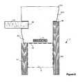
- the cross-section of an appropriate elongate abutment member 7-6 for this purpose is illustrated in Figure 6 .
- the abutment member 7-6 includes a U-shaped recess 56 into which the end of a glass partition 57 can fit.
- Figure 6 also shows that the abutment member 7-6 includes a second abutment surface 58 which is for abutment against the right hand plasterboard 5-2.
- the remaining components of the abutments member 7-6 are the same as those shown in Figure 1 and will be not, therefore, be described again.
- the abutment member 7 was arranged to have one or more tapered sides 15 near the join with the plasterboard 5. As those skilled in the art will appreciate, it is not essential to have such tapered sides. Instead, an abutment member 7 may be provided with sides that are designed to lie flush with the outer surface of the plasterboard 5. In this case, tape or other filler could be used to cover the join between the abutment member 7 and the plasterboard 5.
- the abutment member 7-7 may be arranged to have stepped recesses 59-1 and 59-2 near the join with the plasterboards 5, to allow space for a skim of plaster to be applied to each recess to provide a seamless join between the abutment member 7-7 and the plasterboards 5.
- plasterboards 5 having a tapered edge 61-1 and 61-2 may also be used to provide larger areas around the joins between the abutment member 7-1 and the plasterboards 5 into which a skim of plaster can be made to provide a seamless join.
- one or more wood laths were cast within and along the length of the elongate abutment members 7.
- the wood lath provided a fixing substrate for allowing the abutment member 7 to be fixed to the stud 3 of the partition wall 1 using fixing screws.
- other fixing substrates could be used to achieve this purpose.
- one or more laths may be made out of metal (such as ferous metal or aluminium) or out of any other rigid product.
- the laths also act to strengthen the elongate abutment members 7.
- a separate metal, wood or rope core may be cast within the elongate abutment member 7 for providing further strength.
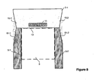
- the abutment 900 is a variation of that illustrated in Figure 1 but having a recessed pocket, 902, adapted to accept the stud 904.
- the recessed pocket 902 enables the abutment to be located or aligned precisely in the correct location relative to the stud; thereby producing a vertical abutment given a vertical stud.
- the width of the recess pocket 902 will depend on the size of the stud being used; the width will be adapted to fit closely around the stud. The widths will therefore be, 50mm, 75mm, 100mm or 145mm or the imperial equivalents, 2", 3", 4", or 6".
- the width of the recess is adapted to fit closely around any other standard width of stud.
- the abutment is preferably attached to the stud when the stud is in place as part of the partition wall.
- the stud may be provided in the abutment before being taken to the installation site, thereby allowing for more accurate fixing and greater stability during transit.
- the recessed pocket 902 typically allows the width W of both limbs of the abutment to be equal on both sides of the partition wall, enabling the plasterboard 906 to align with a flat surface 908 without the requirement for extensive skill by the installer.
- the recess pocket depth D as shown in Figure 9 , of the recess pocket 902 is suitable for allowing the abutment 900 and the plasterboard 906 both to be fixed to the stud using suitable fixings, such as screws (not shown).
- the depth D is half the width of the stud 904. Therefore, the value of D may range from 25mm to 75mm or more depending on the size of the stud used. However, the depth D may vary within this range as long as the primary requirement that both the abutment and plasterboard may be attached to the stud is fulfilled. Therefore, the depth D preferably ranges between 1/4 of the stud width and 3/4 of the stud width, or more preferably the depth D ranges between 1/3 of the stud width and 2/3 of the stud width.
- Screws to attach the abutment 900 to the stud 904 are preferably placed in the area of the taper such that they are hidden from view after the plaster skim is applied.
- the abutment is "back-fixed" with screws (not shown) through the stud into the abutment in the region of the recess pocket; in this case a lath may be required to strengthen the abutment, similar to that shown in Figure 1 .
- the stud 904 When the stud 904 is made from metal it preferably has a wood lath within the stud to enable the fixing screws to affix the abutment more securely.
- the flat surface 908 is preferably approximately 5mm in width; however, alternatively this may range from 3mm to 15mm depending on the application the abutment is used in.
- This surface 908 is used as a leading edge to enable the plasterer to apply the skim of plaster to the taper uniformly.
- the surface 908 is adapted to be in a plane parallel to the outside surface of the plasterboard.
- the plasterer uses the two hard surfaces of the leading edge 908 and the plasterboard 906 to make a smooth flat skim of plaster to produce a seamless joint between the abutment and the partition wall.
- the recess pocket 902 therefore enables the leading edge surface 908 and the outside surface of the plasterboard 906 to be accurately in the same plane.
- the joint between the abutment and the partition wall is taped to produce a joint that is less prone to cracking.
- the tape is placed such that one edge starts just within the tapered region of the abutment, but not encroaching onto the leading edge surface 908, and continues across the join and onto the plasterboard.
- tape of widths between 25 and 35mm are used, and this may for example dictate the width of the taper, which might typically be half the width of standard 25 or 35mm tape.
- both the abutment and the plasterboard has a tapered edge; in this case the tape is again placed such that one edge starts just within the tapered region of the abutment, and finishes just before the tapered edge of the plasterboard finishes.
- the abutment 1000 is shown again with a recess pocket 1002 for accepting the stud 1004 and aligning the abutment with the partition wall.
- a feature 1005 for accepting a glass partition enabling the partition wall to be continued in glass.
- the remaining features are similar to those described above in reference to Figure 9 .
- Figure 10b shows the use of the abutment with both tapered 1006 and non-tapered plasterboard 1008, with the skim of plaster shown to produce the seamless finish in both circumstances, skims 1010 and 1012 respectively.
- the leading edge feature 1014 is again used, on both sides of the abutment, for producing the smooth finish of the skimmed plaster.
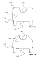
- Figures 11a and 11b Two alternative embodiments of the abutment illustrated in Figures 10 are illustrated in Figures 11a and 11b .
- both these embodiments (1102 and 1104) there is an additional feature 1100 provided for the inclusion of a sealing gasket.
- the feature for accepting the skim of plaster to produce the seamless finish is shown as a recess 1106; however, these embodiments can equally use a taper.
- the recessed pocket 1108 may or may not be required depending on the application of the abutment.
- Figure 11a illustrates the inclusion of angle beads 1110, for example made of metal, cast into the corners of the abutment to provide protection for potentially fragile edges. This feature may be used in any of the above described embodiments, especially those that have sharp edge corners.
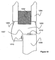
- Figure 12 illustrates an alternative embodiment of the abutment 1200 adapted to provide a door frame, or the frame of any closure.
- a recessed pocket is provided to accept the stud 1202 and align the abutment with the partition wall.
- the plasterboard 1204 adjoins the abutment in a similar fashion, and the tapered skim 1206 is applied in the same manner, using the plasterboard and the leading edge to produce a smooth flat finish.
- the feature 1207 allows the door 1208 to sit within the abutment, producing a conventional door frame effect. Seals 1210 and 1212 may be included to produce a fire rated door frame installation.
- the door frame is preferably provided as a kit of parts suitable for standard door widths of 24, 28, 30, 32, 34, 36 inches, or the equivalent metric sizes.
- the kit provides at least two upright posts and a lintel.
- a taper is also provided to produce a seamless mitred joint between the upright post and horizontal lintel.
- a single skim of plaster can therefore be used to finish both the mitre joint and the joint between the abutment and the partition wall.
- the joint between the mitre is not tapered, thereby enabling ease of manufacture, and distribution (since then the abutment can be manufactured and sold in longer lengths and cut to size on site).
- the door frame embodiment of the abutment is preferably made from a composite material to achieve the desired properties of a door frame, such as durability and fire retardance.
- the composite is plaster based combined with any one, or more, of a number of different materials, such as wood chip/wood pulp mixed in to produce a suitable material.
- the composite material must be capable of accepting mortise features to enable hinges and the like to be attached.
- the door frame may be pre-fitted to include metal/wood plates to attach the hinges and the like.
- FIG. 13a and 13b An alternative embodiment is illustrated in Figures 13a and 13b .
- abutment 1300 an example is provided of horizontal, as opposed to vertical use.
- the abutment is used as a skirting at the bottom of a wall.
- the same taper formation 1302 is utilised to produce a seamless finish between the bottom of the wall 1304 and the abutment 1300.
- quirk details 1306 may be included to produce any desired feature.
- this embodiment may also be utilised at the top of the wall to join the wall to the ceiling.
- the abutment may be used as a cornice to provide a seamless join between a wall and a ceiling.
- FIG. 14 A further embodiment is illustrated in Figure 14 .
- the abutment 1400 is an L-shaped corner-piece to enable the corner of a partition wall to be finished seamlessly.
- the abutment fits around the stud 1402 and the plasterboard 1404 is attached in a similar manner as described above.
- a detail such as a groove for accepting for example a piece of wood may be located
- abutments 7 have been described above. These abutments 7 can be formed either by cutting wet plaster from an elongate rectangular block of plaster or by moulding the plaster using a suitable mould formed from one or more mould pieces. A description will now be given of the way in which a prototype abutment 7 was made by cutting plaster from an elongate block. A description will then be given as to how this prototype can be used to form a latex moulding which can then be used to make a number of similarly profiled abutment members 7.
- All of the above described embodiments are preferably manufactured in a plaster material.
- the abutments are manufactured from composite material to produce the desired properties.
- the technique in which the plaster abutments are finished, such as kiln drying etc, can be varied in order to vary the properties of the abutment to suit different applications.
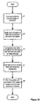
- FIG. 15 is a flow chart illustrating the steps performed to make a prototype abutment member 7.
- step s1 a zinc profile for the required shape of abutment is cut.
- a smooth plaster mix is then made by mixing 20 litres of water with due proportion of herculite and kermicast.
- step s3 a layer of this plaster mix is applied to an elongate rectangular bench mould and a 300mm width by 3m jute scrim is incorporated into this layer of plaster.
- step s5 four laths are incorporated into the plaster for flat fixing with the stud 3 and two laths are incorporated into the plaster for providing strength to the edge of the abutment member 7.
- step s7 a rope scrim is added to the centre of the plaster and the remaining plaster mix is added.
- step s9 the zinc profile is run over the wet plaster until the required shape is cut out and the abutment member 7 is formed.
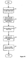
- FIG. 16 is a flow chart illustrating the main steps for a production process for making the above described abutment members.
- step s13 the prototype abutment member made in the manner described above is used to make a latex mould. This involves placing the prototype abutment member 7 within an open top watertight container which is wider than and as deep as the prototype abutment. Latex rubber is then poured over the model and is prevented from leaking by the container. Once the rubber has set, it is peeled off the prototype abutment and is ready for use as the mould for production.
- step s15 the thus formed latex mould is part filled with a base of plaster with GRG (Glass Reinforced Gypsum) matting (200mm wide by 3m long) inserted into the plaster together with 2 laths for fixing.
- GRG matting is formed from fibres similar to those used to make fibre glass boats.
- step s17 after the base of plaster has hardened the main plaster mix is added to fill the latex mould.
- step s19 once all plaster and reinforcements have been incorporated into the mould, a recess is made along the length of the top of the plaster mould for studding purposes. Finally, once the plaster has hardened, the moulded abutment member 7 is removed from the mould. The mould can then be used again to make another abutment member 7 of the same profile.
Landscapes
- Engineering & Computer Science (AREA)
- Architecture (AREA)
- Civil Engineering (AREA)
- Structural Engineering (AREA)
- Ceramic Engineering (AREA)
- Chemical & Material Sciences (AREA)
- Manufacturing & Machinery (AREA)
- Mechanical Engineering (AREA)
- Physics & Mathematics (AREA)
- Electromagnetism (AREA)
- Joining Of Building Structures In Genera (AREA)
- Building Environments (AREA)
- Coating Apparatus (AREA)
Priority Applications (1)
| Application Number | Priority Date | Filing Date | Title |
|---|---|---|---|
| PL07712719T PL2010732T3 (pl) | 2006-04-10 | 2007-02-13 | Podłużny element zakończeniowy z gipsu |
Applications Claiming Priority (4)
| Application Number | Priority Date | Filing Date | Title |
|---|---|---|---|
| GB0607223A GB2437083A (en) | 2006-04-10 | 2006-04-10 | Plaster abutment member for use at ends or junctions of partition walls |
| US11/519,371 US8117791B2 (en) | 2006-04-10 | 2006-09-11 | Abutment member |
| GB0619068A GB2429022B (en) | 2006-04-10 | 2006-09-27 | Abutment member |
| PCT/GB2007/000492 WO2007116198A1 (en) | 2006-04-10 | 2007-02-13 | Elongate abutment member of plaster |
Publications (2)
| Publication Number | Publication Date |
|---|---|
| EP2010732A1 EP2010732A1 (en) | 2009-01-07 |
| EP2010732B1 true EP2010732B1 (en) | 2014-12-03 |
Family
ID=36539698
Family Applications (1)
| Application Number | Title | Priority Date | Filing Date |
|---|---|---|---|
| EP07712719.9A Not-in-force EP2010732B1 (en) | 2006-04-10 | 2007-02-13 | Elongate abutment member of plaster |
Country Status (9)
| Country | Link |
|---|---|
| US (2) | US8117791B2 (pl) |
| EP (1) | EP2010732B1 (pl) |
| DK (1) | DK2010732T3 (pl) |
| EA (1) | EA015214B1 (pl) |
| ES (1) | ES2531625T3 (pl) |
| GB (1) | GB2437083A (pl) |
| PL (1) | PL2010732T3 (pl) |
| PT (1) | PT2010732E (pl) |
| WO (1) | WO2007116198A1 (pl) |
Families Citing this family (7)
| Publication number | Priority date | Publication date | Assignee | Title |
|---|---|---|---|---|
| GB2437083A (en) * | 2006-04-10 | 2007-10-17 | Tony Baccarini | Plaster abutment member for use at ends or junctions of partition walls |
| USD622415S1 (en) | 2006-04-10 | 2010-08-24 | Tony Baccarini | Abutment for partition walls |
| USD597683S1 (en) | 2006-04-10 | 2009-08-04 | Tony Baccarini And Nigel Aulton, Trading As Seamless Abutment Solutions | Abutment for partition walls |
| EP2093346A3 (en) * | 2006-06-28 | 2010-03-31 | Under-Cover | Plastering profile made of reinforced wall plastering material |
| US11933044B2 (en) * | 2017-04-07 | 2024-03-19 | Dynamic Hive, Inc. | Track system for double butt joint glass T-connections |
| US10801212B2 (en) | 2017-10-12 | 2020-10-13 | Donald Kew WOO | Construction elements |
| US20230083940A1 (en) * | 2017-10-12 | 2023-03-16 | Donald Kew WOO | Construction elements |
Family Cites Families (63)
| Publication number | Priority date | Publication date | Assignee | Title |
|---|---|---|---|---|
| US1465539A (en) * | 1921-06-08 | 1923-08-21 | Atterbury Grosvenor | Cementitious sleeper or the like |
| US1555555A (en) * | 1921-09-22 | 1925-09-29 | Bessie D Kennedy | Fireproof wall board |
| US1875576A (en) | 1929-05-06 | 1932-09-06 | Een Johannes Benjamin | Wooden plank house |
| US2110728A (en) * | 1933-01-03 | 1938-03-08 | Certain Teed Prod Corp | Construction material and method of making same |
| US2129497A (en) | 1937-12-20 | 1938-09-06 | I F Laucks | Spline panel joint |
| US2234043A (en) * | 1938-08-24 | 1941-03-04 | Dworetz Joseph | Wall opening construction |
| US2301187A (en) * | 1939-06-19 | 1942-11-10 | Balhatchet William | Plastering device |
| US2261054A (en) * | 1939-09-05 | 1941-10-28 | Randolph L Dietrich | Splay bead |
| US2453221A (en) | 1944-07-21 | 1948-11-09 | Emile S Guignon Jr | Interlocking building units |
| US2537715A (en) | 1945-12-05 | 1951-01-09 | Stead Rupert George | Reinforced wall with ring interlock |
| GB830602A (en) | 1955-06-10 | 1960-03-16 | British Plasterboard Mfg Ltd | Improvements in or relating to the joining of building panels used in the construction of internal walls, ceilings and the like |
| BR6573585D0 (pt) * | 1965-09-29 | 1973-03-08 | Magnesita Sa | Novo e original sistema de fecho em material refratario moldado para arcos aneis e similares |
| US3391509A (en) | 1966-11-03 | 1968-07-09 | Albert A. Fruman | Drywall edge construction and finishing channel |
| US3420016A (en) | 1967-02-06 | 1969-01-07 | Robert L Findlay | Building construction |
| US3465488A (en) * | 1967-03-29 | 1969-09-09 | Peter H Miller | Dry wall structure |
| US3654734A (en) | 1969-06-03 | 1972-04-11 | Stratford Ind Inc | Adjustable door or window frame |
| US3935049A (en) * | 1974-07-15 | 1976-01-27 | Ashland Oil, Inc. | Method of covering a substrate by overidge bonding of a covering material about the edges of the substrate |
| US3973371A (en) | 1974-10-21 | 1976-08-10 | Heller Stephen M | Furniture and wall structural system |
| USD245018S (en) | 1975-06-25 | 1977-07-12 | Westrock Industries Inc. | Upright for an overground swimming pool |
| USD251804S (en) | 1977-02-11 | 1979-05-08 | American Standard Inc. | Door frame or similar article |
| GB2209135B (en) * | 1987-08-29 | 1990-12-05 | Clancast Products Limited | Making elongate moulded products |
| US4753622A (en) * | 1987-10-05 | 1988-06-28 | Yoshitsugu Nakama | Building block kit |
| US4837993A (en) | 1988-09-06 | 1989-06-13 | Studenski Arnold H | Tempered glass door fitting apparatus |
| US4964250A (en) | 1989-08-30 | 1990-10-23 | Soltech, Inc. | Modular acoustical panel and method of making same |
| US5115605A (en) * | 1990-02-16 | 1992-05-26 | Glenn Technologies, Inc. | Window unit |
| GB2269839B (en) | 1991-04-01 | 1995-06-07 | Walter Lindal | Wooden frame building construction |
| USD372546S (en) | 1992-11-12 | 1996-08-06 | Pelosi Lee J | Prehung gauged cove base |
| DE4300130C2 (de) | 1993-01-06 | 1996-05-09 | Gima Gipser Und Malerbedarf Gm | Erzeugnis zum Abdecken und Einfassen von Kanten, Stürzen oder Laibungen bei Bauwerken |
| US6148883A (en) | 1993-03-22 | 2000-11-21 | Wilson; Bryan Alexander | Wood trim system |
| US5501050A (en) | 1993-10-18 | 1996-03-26 | Ruel; Raymond | Shingled tile block siding facade for buildings |
| US5755066A (en) * | 1993-12-02 | 1998-05-26 | Becker; Duane William | Slip track assembly |
| US5544463A (en) | 1994-08-30 | 1996-08-13 | Bergin; Blaine R. | Prefinished corner bead |
| US5819458A (en) * | 1995-09-29 | 1998-10-13 | Hadden; David M. | Reinforced picture frame moulding |
| US5809726A (en) | 1996-08-21 | 1998-09-22 | Spude; Gerald T. | Foundation construction system |
| US5934030A (en) | 1997-08-29 | 1999-08-10 | Composite Structures, Inc. | Door frame |
| DE29809789U1 (de) | 1998-05-30 | 1998-09-17 | Schlüter-Systems GmbH, 58640 Iserlohn | Profil zur Eckausbildung an mit Keramikplatten belegten Gebäudeflächen |
| US6228507B1 (en) * | 1998-08-24 | 2001-05-08 | Richard D. W. Hahn | Ornamental plaster crown molding |
| US6176053B1 (en) * | 1998-08-27 | 2001-01-23 | Roger C. A. St. Germain | Wall track assembly and method for installing the same |
| CA2252016C (en) | 1998-10-28 | 2008-01-15 | David Murray Simonar | Method and apparatus for mounting architectural moldings |
| FR2793269B1 (fr) * | 1999-05-03 | 2003-04-04 | Irina Romanenko | Dispositif destine a faciliter la realisation d'extremites de cloisons en platre, et la jonction entre elles ou avec des murs, des parties rampantes, ou des plafonds |
| US6119432A (en) | 1999-09-03 | 2000-09-19 | Niemann; Michael H. | Concrete form wall building system |
| DE10102882A1 (de) | 2001-01-23 | 2002-07-25 | Josef Klemens | Fugenprofil |
| DE10041362A1 (de) | 2000-08-23 | 2002-03-07 | Josef Klemens | Verbindungsprofil |
| US6722092B2 (en) | 2000-05-17 | 2004-04-20 | Phillips Manufacturing Co. | Paper bead |
| USD467007S1 (en) | 2000-05-18 | 2002-12-10 | Dietrich Industries, Inc. | Building component support header |
| US6408576B1 (en) * | 2000-10-20 | 2002-06-25 | Douglas Roth | Arch mold apparatus and method for making arches |
| AUPR090400A0 (en) | 2000-10-20 | 2000-11-16 | Lafarge Plasterboard Pty Ltd | Partition wall |
| AUPR173700A0 (en) | 2000-11-28 | 2000-12-21 | Csr Limited | Paper wrapped gypsum building component and manufacture thereof |
| CZ20032254A3 (cs) | 2001-02-20 | 2003-12-17 | Malgorzata Wesolowska | Podlahová lišta s dokončovacími prvky |
| DE20104657U1 (de) | 2001-03-16 | 2001-06-21 | Lorentz, Karl-Heinz, 66333 Völklingen | Putzprofile |
| US20030005660A1 (en) | 2001-06-22 | 2003-01-09 | Stibolt Paul E. | Drywall corner finishing device |
| WO2003076732A1 (en) | 2002-03-04 | 2003-09-18 | Mark Spurlock | Improved apparatus for forming a corner of a wall |
| US6604331B1 (en) | 2002-07-09 | 2003-08-12 | Steven Pallas | Baseboard molding strip unit |
| US6990778B2 (en) | 2002-09-18 | 2006-01-31 | Passeno James K | Brick veneer assembly |
| US20040055245A1 (en) * | 2002-09-23 | 2004-03-25 | Fitch Kent C. | Wall cap corner aid |
| US20050011159A1 (en) | 2003-07-14 | 2005-01-20 | Standal Douglas J. | Cove elements and floor coatings and methods for installing |
| US7404272B2 (en) | 2004-06-23 | 2008-07-29 | Piche Michel | Protective baseboard |
| GB2437083A (en) * | 2006-04-10 | 2007-10-17 | Tony Baccarini | Plaster abutment member for use at ends or junctions of partition walls |
| USD622415S1 (en) | 2006-04-10 | 2010-08-24 | Tony Baccarini | Abutment for partition walls |
| USD597683S1 (en) | 2006-04-10 | 2009-08-04 | Tony Baccarini And Nigel Aulton, Trading As Seamless Abutment Solutions | Abutment for partition walls |
| US20090038250A1 (en) * | 2007-08-10 | 2009-02-12 | Leonard Frenkil | Reinforced wallboard |
| USD581545S1 (en) | 2007-09-25 | 2008-11-25 | Dove Michael J | Frame molding for an entrance opening |
| USD629125S1 (en) | 2009-09-04 | 2010-12-14 | Johnsonite Inc. | Wall base |
-
2006
- 2006-04-10 GB GB0607223A patent/GB2437083A/en not_active Withdrawn
- 2006-09-11 US US11/519,371 patent/US8117791B2/en not_active Expired - Fee Related
-
2007
- 2007-02-13 PL PL07712719T patent/PL2010732T3/pl unknown
- 2007-02-13 US US12/594,296 patent/US20100192494A1/en not_active Abandoned
- 2007-02-13 ES ES07712719.9T patent/ES2531625T3/es active Active
- 2007-02-13 EP EP07712719.9A patent/EP2010732B1/en not_active Not-in-force
- 2007-02-13 DK DK07712719.9T patent/DK2010732T3/en active
- 2007-02-13 WO PCT/GB2007/000492 patent/WO2007116198A1/en not_active Ceased
- 2007-02-13 PT PT07712719T patent/PT2010732E/pt unknown
- 2007-02-13 EA EA200870418A patent/EA015214B1/ru not_active IP Right Cessation
Also Published As
| Publication number | Publication date |
|---|---|
| PT2010732E (pt) | 2015-03-04 |
| DK2010732T3 (en) | 2015-03-02 |
| EA015214B1 (ru) | 2011-06-30 |
| EA200870418A1 (ru) | 2009-04-28 |
| EP2010732A1 (en) | 2009-01-07 |
| WO2007116198A1 (en) | 2007-10-18 |
| US8117791B2 (en) | 2012-02-21 |
| GB0607223D0 (en) | 2006-05-17 |
| GB2437083A (en) | 2007-10-17 |
| US20100192494A1 (en) | 2010-08-05 |
| ES2531625T3 (es) | 2015-03-18 |
| PL2010732T3 (pl) | 2015-08-31 |
| US20070245654A1 (en) | 2007-10-25 |
Similar Documents
| Publication | Publication Date | Title |
|---|---|---|
| US8151539B2 (en) | Panel building system | |
| AU2017203291B2 (en) | Stronger wall system | |
| US9151046B1 (en) | Concrete slab having integral wall base forms and wall base plates for automated construction and system thereof | |
| EP2010732B1 (en) | Elongate abutment member of plaster | |
| US8069622B2 (en) | Systems and methods for finishing a penetration in a concrete structure during construction | |
| AU2017258845B2 (en) | Improved composite concrete and framing system and method for building construction | |
| US20210207381A1 (en) | Bead stop for a wall having interior cement board layer | |
| KR100274218B1 (ko) | 건축물 내, 외장용 칼라록 단열판재와 그의 제조 및 시공방법 | |
| US20190323235A1 (en) | Pre-shaped form construction components, system, and method of construction using the same | |
| KR20150008332A (ko) | 건식마감이 용이한 단열패널 연결유닛 및 이를 이용한 철근콘크리트 벽체 시공방법 | |
| US8490354B2 (en) | Apparatus, system, and method for constructing a wall using wall blocks | |
| CN1260020A (zh) | 组合式夹合板及房屋建筑方法 | |
| Plunkett | Construction and Detailing for Interior Design Second Edition | |
| KR20120000702A (ko) | 경량 성형재를 구비한 조립식 영구거푸집 유닛 및 이를 이용한 벽체 시공방법 | |
| KR102335307B1 (ko) | 벽체 방수와 바닥 방수판의 연결 부위 방수를 보강하는 구조 및 이의 시공방법 | |
| KR20120006263A (ko) | 벽체 시공방법 | |
| US20060070327A1 (en) | Wall block and method of manufacture thereof | |
| GB2429022A (en) | Abutment member | |
| RU223852U1 (ru) | Угловой строительный элемент из гипсосодержащего материала | |
| JP7387658B2 (ja) | シャッタゲート及びシャッタゲートの施工方法 | |
| BR102018075380A2 (pt) | Sistema construtivo em blocos de concreto celular | |
| RU77623U1 (ru) | Строительный элемент | |
| FI20215212A1 (fi) | Menetelmä tilaelementin rakentamiseksi ja elementtirakenteinen lattialaatta | |
| AU2021201194A1 (en) | Rend R Wall | |
| IE20200089A1 (en) | A construction arrangement and a method of connecting panels |
Legal Events
| Date | Code | Title | Description |
|---|---|---|---|
| PUAI | Public reference made under article 153(3) epc to a published international application that has entered the european phase |
Free format text: ORIGINAL CODE: 0009012 |
|
| 17P | Request for examination filed |
Effective date: 20081107 |
|
| AK | Designated contracting states |
Kind code of ref document: A1 Designated state(s): AT BE BG CH CY CZ DE DK EE ES FI FR GB GR HU IE IS IT LI LT LU LV MC NL PL PT RO SE SI SK TR |
|
| AX | Request for extension of the european patent |
Extension state: AL BA HR MK RS |
|
| DAX | Request for extension of the european patent (deleted) | ||
| 17Q | First examination report despatched |
Effective date: 20130222 |
|
| GRAP | Despatch of communication of intention to grant a patent |
Free format text: ORIGINAL CODE: EPIDOSNIGR1 |
|
| INTG | Intention to grant announced |
Effective date: 20140701 |
|
| GRAS | Grant fee paid |
Free format text: ORIGINAL CODE: EPIDOSNIGR3 |
|
| GRAA | (expected) grant |
Free format text: ORIGINAL CODE: 0009210 |
|
| AK | Designated contracting states |
Kind code of ref document: B1 Designated state(s): AT BE BG CH CY CZ DE DK EE ES FI FR GB GR HU IE IS IT LI LT LU LV MC NL PL PT RO SE SI SK TR |
|
| REG | Reference to a national code |
Ref country code: GB Ref legal event code: FG4D |
|
| REG | Reference to a national code |
Ref country code: CH Ref legal event code: EP Ref country code: AT Ref legal event code: REF Ref document number: 699483 Country of ref document: AT Kind code of ref document: T Effective date: 20141215 |
|
| REG | Reference to a national code |
Ref country code: IE Ref legal event code: FG4D |
|
| REG | Reference to a national code |
Ref country code: DE Ref legal event code: R096 Ref document number: 602007039526 Country of ref document: DE Effective date: 20150115 |
|
| REG | Reference to a national code |
Ref country code: DK Ref legal event code: T3 Effective date: 20150226 |
|
| REG | Reference to a national code |
Ref country code: PT Ref legal event code: SC4A Free format text: AVAILABILITY OF NATIONAL TRANSLATION Effective date: 20150226 |
|
| REG | Reference to a national code |
Ref country code: SE Ref legal event code: TRGR |
|
| REG | Reference to a national code |
Ref country code: ES Ref legal event code: FG2A Ref document number: 2531625 Country of ref document: ES Kind code of ref document: T3 Effective date: 20150318 Ref country code: NL Ref legal event code: T3 |
|
| PG25 | Lapsed in a contracting state [announced via postgrant information from national office to epo] |
Ref country code: FI Free format text: LAPSE BECAUSE OF FAILURE TO SUBMIT A TRANSLATION OF THE DESCRIPTION OR TO PAY THE FEE WITHIN THE PRESCRIBED TIME-LIMIT Effective date: 20141203 Ref country code: LT Free format text: LAPSE BECAUSE OF FAILURE TO SUBMIT A TRANSLATION OF THE DESCRIPTION OR TO PAY THE FEE WITHIN THE PRESCRIBED TIME-LIMIT Effective date: 20141203 |
|
| REG | Reference to a national code |
Ref country code: LT Ref legal event code: MG4D |
|
| PG25 | Lapsed in a contracting state [announced via postgrant information from national office to epo] |
Ref country code: LV Free format text: LAPSE BECAUSE OF FAILURE TO SUBMIT A TRANSLATION OF THE DESCRIPTION OR TO PAY THE FEE WITHIN THE PRESCRIBED TIME-LIMIT Effective date: 20141203 Ref country code: GR Free format text: LAPSE BECAUSE OF FAILURE TO SUBMIT A TRANSLATION OF THE DESCRIPTION OR TO PAY THE FEE WITHIN THE PRESCRIBED TIME-LIMIT Effective date: 20150304 Ref country code: CY Free format text: LAPSE BECAUSE OF FAILURE TO SUBMIT A TRANSLATION OF THE DESCRIPTION OR TO PAY THE FEE WITHIN THE PRESCRIBED TIME-LIMIT Effective date: 20141203 |
|
| PG25 | Lapsed in a contracting state [announced via postgrant information from national office to epo] |
Ref country code: RO Free format text: LAPSE BECAUSE OF FAILURE TO SUBMIT A TRANSLATION OF THE DESCRIPTION OR TO PAY THE FEE WITHIN THE PRESCRIBED TIME-LIMIT Effective date: 20141203 Ref country code: EE Free format text: LAPSE BECAUSE OF FAILURE TO SUBMIT A TRANSLATION OF THE DESCRIPTION OR TO PAY THE FEE WITHIN THE PRESCRIBED TIME-LIMIT Effective date: 20141203 Ref country code: SK Free format text: LAPSE BECAUSE OF FAILURE TO SUBMIT A TRANSLATION OF THE DESCRIPTION OR TO PAY THE FEE WITHIN THE PRESCRIBED TIME-LIMIT Effective date: 20141203 |
|
| PG25 | Lapsed in a contracting state [announced via postgrant information from national office to epo] |
Ref country code: IS Free format text: LAPSE BECAUSE OF FAILURE TO SUBMIT A TRANSLATION OF THE DESCRIPTION OR TO PAY THE FEE WITHIN THE PRESCRIBED TIME-LIMIT Effective date: 20150403 |
|
| REG | Reference to a national code |
Ref country code: PL Ref legal event code: T3 |
|
| REG | Reference to a national code |
Ref country code: DE Ref legal event code: R097 Ref document number: 602007039526 Country of ref document: DE |
|
| PG25 | Lapsed in a contracting state [announced via postgrant information from national office to epo] |
Ref country code: LU Free format text: LAPSE BECAUSE OF FAILURE TO SUBMIT A TRANSLATION OF THE DESCRIPTION OR TO PAY THE FEE WITHIN THE PRESCRIBED TIME-LIMIT Effective date: 20150213 |
|
| PLBE | No opposition filed within time limit |
Free format text: ORIGINAL CODE: 0009261 |
|
| STAA | Information on the status of an ep patent application or granted ep patent |
Free format text: STATUS: NO OPPOSITION FILED WITHIN TIME LIMIT |
|
| PG25 | Lapsed in a contracting state [announced via postgrant information from national office to epo] |
Ref country code: MC Free format text: LAPSE BECAUSE OF FAILURE TO SUBMIT A TRANSLATION OF THE DESCRIPTION OR TO PAY THE FEE WITHIN THE PRESCRIBED TIME-LIMIT Effective date: 20141203 |
|
| 26N | No opposition filed |
Effective date: 20150904 |
|
| REG | Reference to a national code |
Ref country code: FR Ref legal event code: PLFP Year of fee payment: 10 |
|
| PG25 | Lapsed in a contracting state [announced via postgrant information from national office to epo] |
Ref country code: SI Free format text: LAPSE BECAUSE OF FAILURE TO SUBMIT A TRANSLATION OF THE DESCRIPTION OR TO PAY THE FEE WITHIN THE PRESCRIBED TIME-LIMIT Effective date: 20141203 |
|
| REG | Reference to a national code |
Ref country code: AT Ref legal event code: UEP Ref document number: 699483 Country of ref document: AT Kind code of ref document: T Effective date: 20141203 |
|
| REG | Reference to a national code |
Ref country code: FR Ref legal event code: PLFP Year of fee payment: 11 |
|
| PGFP | Annual fee paid to national office [announced via postgrant information from national office to epo] |
Ref country code: PL Payment date: 20161130 Year of fee payment: 11 |
|
| PGFP | Annual fee paid to national office [announced via postgrant information from national office to epo] |
Ref country code: FR Payment date: 20170112 Year of fee payment: 11 Ref country code: SE Payment date: 20170213 Year of fee payment: 11 Ref country code: CH Payment date: 20170214 Year of fee payment: 11 Ref country code: DE Payment date: 20170207 Year of fee payment: 11 |
|
| PG25 | Lapsed in a contracting state [announced via postgrant information from national office to epo] |
Ref country code: HU Free format text: LAPSE BECAUSE OF FAILURE TO SUBMIT A TRANSLATION OF THE DESCRIPTION OR TO PAY THE FEE WITHIN THE PRESCRIBED TIME-LIMIT; INVALID AB INITIO Effective date: 20070213 Ref country code: BG Free format text: LAPSE BECAUSE OF FAILURE TO SUBMIT A TRANSLATION OF THE DESCRIPTION OR TO PAY THE FEE WITHIN THE PRESCRIBED TIME-LIMIT Effective date: 20141203 |
|
| PGFP | Annual fee paid to national office [announced via postgrant information from national office to epo] |
Ref country code: PT Payment date: 20170208 Year of fee payment: 11 Ref country code: BE Payment date: 20161228 Year of fee payment: 11 Ref country code: CZ Payment date: 20170126 Year of fee payment: 11 Ref country code: NL Payment date: 20170210 Year of fee payment: 11 Ref country code: IE Payment date: 20170209 Year of fee payment: 11 Ref country code: AT Payment date: 20170125 Year of fee payment: 11 Ref country code: DK Payment date: 20170210 Year of fee payment: 11 Ref country code: GB Payment date: 20170208 Year of fee payment: 11 |
|
| PGFP | Annual fee paid to national office [announced via postgrant information from national office to epo] |
Ref country code: IT Payment date: 20170221 Year of fee payment: 11 Ref country code: ES Payment date: 20170110 Year of fee payment: 11 Ref country code: TR Payment date: 20170112 Year of fee payment: 11 |
|
| REG | Reference to a national code |
Ref country code: DE Ref legal event code: R119 Ref document number: 602007039526 Country of ref document: DE |
|
| REG | Reference to a national code |
Ref country code: CH Ref legal event code: PL |
|
| REG | Reference to a national code |
Ref country code: DK Ref legal event code: EBP Effective date: 20180228 |
|
| REG | Reference to a national code |
Ref country code: SE Ref legal event code: EUG |
|
| REG | Reference to a national code |
Ref country code: NL Ref legal event code: MM Effective date: 20180301 |
|
| REG | Reference to a national code |
Ref country code: AT Ref legal event code: MM01 Ref document number: 699483 Country of ref document: AT Kind code of ref document: T Effective date: 20180213 |
|
| GBPC | Gb: european patent ceased through non-payment of renewal fee |
Effective date: 20180213 |
|
| PG25 | Lapsed in a contracting state [announced via postgrant information from national office to epo] |
Ref country code: PT Free format text: LAPSE BECAUSE OF NON-PAYMENT OF DUE FEES Effective date: 20180813 Ref country code: SE Free format text: LAPSE BECAUSE OF NON-PAYMENT OF DUE FEES Effective date: 20180214 |
|
| REG | Reference to a national code |
Ref country code: IE Ref legal event code: MM4A |
|
| REG | Reference to a national code |
Ref country code: BE Ref legal event code: FP Effective date: 20150303 Ref country code: BE Ref legal event code: MM Effective date: 20180228 |
|
| PG25 | Lapsed in a contracting state [announced via postgrant information from national office to epo] |
Ref country code: LI Free format text: LAPSE BECAUSE OF NON-PAYMENT OF DUE FEES Effective date: 20180228 Ref country code: CZ Free format text: LAPSE BECAUSE OF NON-PAYMENT OF DUE FEES Effective date: 20180213 Ref country code: AT Free format text: LAPSE BECAUSE OF NON-PAYMENT OF DUE FEES Effective date: 20180213 Ref country code: CH Free format text: LAPSE BECAUSE OF NON-PAYMENT OF DUE FEES Effective date: 20180228 |
|
| REG | Reference to a national code |
Ref country code: FR Ref legal event code: ST Effective date: 20181031 |
|
| PG25 | Lapsed in a contracting state [announced via postgrant information from national office to epo] |
Ref country code: NL Free format text: LAPSE BECAUSE OF NON-PAYMENT OF DUE FEES Effective date: 20180301 |
|
| PG25 | Lapsed in a contracting state [announced via postgrant information from national office to epo] |
Ref country code: DE Free format text: LAPSE BECAUSE OF NON-PAYMENT OF DUE FEES Effective date: 20180901 Ref country code: DK Free format text: LAPSE BECAUSE OF NON-PAYMENT OF DUE FEES Effective date: 20180228 Ref country code: IE Free format text: LAPSE BECAUSE OF NON-PAYMENT OF DUE FEES Effective date: 20180213 |
|
| PG25 | Lapsed in a contracting state [announced via postgrant information from national office to epo] |
Ref country code: BE Free format text: LAPSE BECAUSE OF NON-PAYMENT OF DUE FEES Effective date: 20180228 Ref country code: GB Free format text: LAPSE BECAUSE OF NON-PAYMENT OF DUE FEES Effective date: 20180213 Ref country code: FR Free format text: LAPSE BECAUSE OF NON-PAYMENT OF DUE FEES Effective date: 20180228 Ref country code: IT Free format text: LAPSE BECAUSE OF NON-PAYMENT OF DUE FEES Effective date: 20180213 |
|
| REG | Reference to a national code |
Ref country code: ES Ref legal event code: FD2A Effective date: 20190801 |
|
| PG25 | Lapsed in a contracting state [announced via postgrant information from national office to epo] |
Ref country code: ES Free format text: LAPSE BECAUSE OF NON-PAYMENT OF DUE FEES Effective date: 20180214 |
|
| PG25 | Lapsed in a contracting state [announced via postgrant information from national office to epo] |
Ref country code: PL Free format text: LAPSE BECAUSE OF NON-PAYMENT OF DUE FEES Effective date: 20180213 |
|
| PG25 | Lapsed in a contracting state [announced via postgrant information from national office to epo] |
Ref country code: TR Free format text: LAPSE BECAUSE OF NON-PAYMENT OF DUE FEES Effective date: 20180213 |