EP2010094B1 - Kieferorthopädische implantatvorrichtung - Google Patents
Kieferorthopädische implantatvorrichtung Download PDFInfo
- Publication number
- EP2010094B1 EP2010094B1 EP07732310.3A EP07732310A EP2010094B1 EP 2010094 B1 EP2010094 B1 EP 2010094B1 EP 07732310 A EP07732310 A EP 07732310A EP 2010094 B1 EP2010094 B1 EP 2010094B1
- Authority
- EP
- European Patent Office
- Prior art keywords
- head portion
- undercut
- recess
- implant
- channel
- Prior art date
- Legal status (The legal status is an assumption and is not a legal conclusion. Google has not performed a legal analysis and makes no representation as to the accuracy of the status listed.)
- Active
Links
- 239000007943 implant Substances 0.000 title claims description 89
- 210000000988 bone and bone Anatomy 0.000 claims description 22
- 238000003780 insertion Methods 0.000 claims description 22
- 230000037431 insertion Effects 0.000 claims description 22
- 238000010079 rubber tapping Methods 0.000 claims description 6
- 238000005553 drilling Methods 0.000 claims description 5
- 230000035515 penetration Effects 0.000 claims description 3
- 238000000034 method Methods 0.000 description 12
- 239000000463 material Substances 0.000 description 6
- 230000001054 cortical effect Effects 0.000 description 4
- 210000001519 tissue Anatomy 0.000 description 4
- 210000004872 soft tissue Anatomy 0.000 description 3
- 230000000295 complement effect Effects 0.000 description 2
- 230000002093 peripheral effect Effects 0.000 description 2
- 238000004080 punching Methods 0.000 description 2
- 210000004746 tooth root Anatomy 0.000 description 2
- 238000007666 vacuum forming Methods 0.000 description 2
- 230000000007 visual effect Effects 0.000 description 2
- FAPWRFPIFSIZLT-UHFFFAOYSA-M Sodium chloride Chemical compound [Na+].[Cl-] FAPWRFPIFSIZLT-UHFFFAOYSA-M 0.000 description 1
- 229910000831 Steel Inorganic materials 0.000 description 1
- 229910001069 Ti alloy Inorganic materials 0.000 description 1
- 229910000883 Ti6Al4V Inorganic materials 0.000 description 1
- RTAQQCXQSZGOHL-UHFFFAOYSA-N Titanium Chemical compound [Ti] RTAQQCXQSZGOHL-UHFFFAOYSA-N 0.000 description 1
- 210000003484 anatomy Anatomy 0.000 description 1
- 230000015572 biosynthetic process Effects 0.000 description 1
- OSGAYBCDTDRGGQ-UHFFFAOYSA-L calcium sulfate Inorganic materials [Ca+2].[O-]S([O-])(=O)=O OSGAYBCDTDRGGQ-UHFFFAOYSA-L 0.000 description 1
- 238000004891 communication Methods 0.000 description 1
- 238000002591 computed tomography Methods 0.000 description 1
- -1 for example Substances 0.000 description 1
- 239000011507 gypsum plaster Substances 0.000 description 1
- 238000007373 indentation Methods 0.000 description 1
- 230000002262 irrigation Effects 0.000 description 1
- 238000003973 irrigation Methods 0.000 description 1
- 229910052751 metal Inorganic materials 0.000 description 1
- 239000002184 metal Substances 0.000 description 1
- 238000012544 monitoring process Methods 0.000 description 1
- 239000004033 plastic Substances 0.000 description 1
- 229920003023 plastic Polymers 0.000 description 1
- 239000011780 sodium chloride Substances 0.000 description 1
- 239000010959 steel Substances 0.000 description 1
- 239000010936 titanium Substances 0.000 description 1
- 229910052719 titanium Inorganic materials 0.000 description 1
- 238000012546 transfer Methods 0.000 description 1
Images


Classifications
-
- A—HUMAN NECESSITIES
- A61—MEDICAL OR VETERINARY SCIENCE; HYGIENE
- A61C—DENTISTRY; APPARATUS OR METHODS FOR ORAL OR DENTAL HYGIENE
- A61C8/00—Means to be fixed to the jaw-bone for consolidating natural teeth or for fixing dental prostheses thereon; Dental implants; Implanting tools
-
- A—HUMAN NECESSITIES
- A61—MEDICAL OR VETERINARY SCIENCE; HYGIENE
- A61C—DENTISTRY; APPARATUS OR METHODS FOR ORAL OR DENTAL HYGIENE
- A61C8/00—Means to be fixed to the jaw-bone for consolidating natural teeth or for fixing dental prostheses thereon; Dental implants; Implanting tools
- A61C8/0018—Means to be fixed to the jaw-bone for consolidating natural teeth or for fixing dental prostheses thereon; Dental implants; Implanting tools characterised by the shape
- A61C8/0022—Self-screwing
- A61C8/0024—Self-screwing with self-boring cutting edge
-
- A—HUMAN NECESSITIES
- A61—MEDICAL OR VETERINARY SCIENCE; HYGIENE
- A61C—DENTISTRY; APPARATUS OR METHODS FOR ORAL OR DENTAL HYGIENE
- A61C1/00—Dental machines for boring or cutting ; General features of dental machines or apparatus, e.g. hand-piece design
- A61C1/08—Machine parts specially adapted for dentistry
- A61C1/082—Positioning or guiding, e.g. of drills
- A61C1/084—Positioning or guiding, e.g. of drills of implanting tools
-
- A—HUMAN NECESSITIES
- A61—MEDICAL OR VETERINARY SCIENCE; HYGIENE
- A61C—DENTISTRY; APPARATUS OR METHODS FOR ORAL OR DENTAL HYGIENE
- A61C8/00—Means to be fixed to the jaw-bone for consolidating natural teeth or for fixing dental prostheses thereon; Dental implants; Implanting tools
- A61C8/0087—Means for sterile storage or manipulation of dental implants
-
- A—HUMAN NECESSITIES
- A61—MEDICAL OR VETERINARY SCIENCE; HYGIENE
- A61C—DENTISTRY; APPARATUS OR METHODS FOR ORAL OR DENTAL HYGIENE
- A61C8/00—Means to be fixed to the jaw-bone for consolidating natural teeth or for fixing dental prostheses thereon; Dental implants; Implanting tools
- A61C8/0089—Implanting tools or instruments
-
- A—HUMAN NECESSITIES
- A61—MEDICAL OR VETERINARY SCIENCE; HYGIENE
- A61C—DENTISTRY; APPARATUS OR METHODS FOR ORAL OR DENTAL HYGIENE
- A61C8/00—Means to be fixed to the jaw-bone for consolidating natural teeth or for fixing dental prostheses thereon; Dental implants; Implanting tools
- A61C8/0093—Features of implants not otherwise provided for
- A61C8/0096—Implants for use in orthodontic treatment
Definitions
- This invention relates to an orthodontic implant device.
- modified bone screws also referred to as "mini-implants”
- mini-implants to provide independent anchor points in the jaw bone of a patient to allow both direct and indirect orthodontic traction.
- bone screws are used to allow the attachment of fixed orthodontic appliances thereto, such as braces, in order to allow the teeth of a patient to be moved in a required direction.
- One such orthodontic implant is known from WO-A-01/37752 .
- a conventional mini bone screw typically includes a screw head with a slot or cross recess defined in a top surface thereof to allow engagement of an insertion tool thereto, such as for example a screw driver.
- a threaded body is provided below the screw head and the threaded body typically has a narrowing taper towards a tip at the opposite end of the screw from the screw head.
- a recess or undercut can be provided between a lower surface of the screw head and the threaded body to allow the attachment of a component of an orthodontic appliance thereto, such as an elastic band of a brace.
- a problem with providing a recess between the threaded body and the screw head is that it provides the screw with a high upper profile, thereby causing discomfort to a user.
- due to the side of the screw head it is often difficult to insert a band or part of orthodontic appliance over the screw head.
- mini bone screws in a patient have also been found critical to their success.
- the insertion technique used should maximize the available bone volume whilst avoiding adjacent anatomical structures, such as dental roots, neurovascular tissues and nasomaxillary cavities.
- planned tooth movement should be taken into account since improper positioning may result in interference with the required tooth movement and limit the effectiveness of the skeletal anchorage.
- it is often difficult to accurately position mini bone screws due to visual obstruction and restricted instrument access in the patient's mouth, particularly when the mini bone screws are to be placed in posterior or palatal locations.
- problems can arise when the planning of treatment and the actual implant insertion is undertaken by different clinicians.
- wire guide which is radiographed in place in the patient's mouth to show the relationship between the planned insertion site and the adjacent dental roots.
- wire guides provide only limited topographical information, rather than a direct indication of the implant angulation.
- an orthodontic implant device said device including a head portion, engagement means provided on or associated with the head portion to allow an insertion instrument to engage therewith in use and a body portion extending from a lower surface of the head portion, and wherein at least one recess dr undercut is provided substantially internally of the head portion.
- the at least one recess or undercut is provided in addition to or in association with the engagement means of the head portion.
- the at least one recess or undercut is arranged so as to provide a point of attachment for at least part of an orthodontic appliance thereto.
- This allows the implant device to have a lower profile than conventional implant devices having a recess or undercut provided between a lower surface of the implant or head portion and the body portion.
- the recess or undercut also reduces the likelihood of the orthodontic appliance part from coming loose in the patient's mouth and removes the requirement for a secondary attachment wire or means therewith.
- the orthodontic implant device is a "mini-implant" device.
- the head portion includes or is associated with a neck portion and the engagement means are associated with the neck portion.
- the engagement means can be associated with a pentagonal surface of the neck portion in one embodiment.
- the engagement means can be associated with an upper surface of the head portion.
- the neck portion is typically provided between the head portion and the body portion, the body potion extending from a lower surface of the neck portion and the head portion extending from an upper surface of the neck portion.
- the orthodontic appliance part includes a wire, tie, band, rubber or elastic piece, ligature and/or the like.
- the engagement means includes one or more slots defined in an upper surface of the head portion. In one embodiment at least two slots are provided on the upper surface of the head portion to form a cross. It is to be appreciated that the engagement means provided on the upper surface of the head portion need not be used to allow engagement of an insertion tool therewith and can simply be provided to have the orthodontic appliance part be located with the undercut associated with the engagement means.
- the implant device is in the form of a screw and the body portion is at least partially threaded.
- the insertion instrument can be in the form of a screw driver.
- the head of the screw driver can engage with the neck portion and/or head portion of the device and/or the slots or other engagement means defined on the head portion and/or neck portion.
- the at least one recess or undercut is in addition to the engagement means.
- the at least one recess or undercut is associated with the one or more slots defined in the upper surface of the head portion.
- At least one recess or undercut is provided substantially internally of the screw head portion.
- the at least one recess or undercut is in communication with the one or more slots.
- the slot is in the form of a channel with the top open end of the channel adjacent the upper surface of the head portion, the side walls and the base of the channel provided below and/or a pre-determined distance below the upper surface of the head portion.
- the base of the channel is provided substantially vertically below and/or substantially directly opposite the open end of the channel.
- the channel can have open side ends adjacent the external side of the head portion.
- the at least one recess or undercut is provided laterally or on at least one side of the base of the channel slot (i.e. the undercut or recess is defined in a side wall or walls of the channel slot). Further preferably the at least one recess or undercut is provided on both sides of the base of the channel slot.
- the at least one recess or undercut is provided substantially perpendicular to the substantially vertical or upright section or side walls of the channel slot.
- the base of the recess or undercut is substantially continuous or planar with the base of the channel slot.
- the base of the recess or undercut could be provided at a different height (i.e. a pre-determined distance above or below) compared to the base of the channel slot.
- the at least one recess or undercut is of such dimensions to allow a wire or part of an orthodontic appliance to be located therewith (i.e. whilst keeping the slot of the engagement means clear for engagement with an insertion tool).
- a top wall of the recess or undercut typically acts as a hook or engagement surface for the wire or orthodontic appliance part when located therewith in use.
- the at least one recess or undercut can be said to be defined “internally" of the head portion in that it is within the boundary of the exterior walls of the head portion.
- the at least one recess or undercut communicates with at least one further recess or undercut provided around at least part of a peripheral edge, side wall or "externally" of the head portion.
- the at least one further recess or undercut can be provided for the attachment of one or more wires or orthodontic appliance parts thereto.
- the recess or undercut is provided laterally or substantially perpendicularly to the external side walls of the head portion.
- the at least one further recess or undercut provided around a peripheral edge of the head portion is typically provided a predetermined distance below the upper surface of the head portion.
- attachment means are provided on the head portion for the attachment or one or more wires of orthodontic appliance parts thereto.
- the attachment means are preferably in addition to the "internal" undercut or recess and/or the further or “external” undercut or recess.
- the attachment means can include one or more apertures, channels, slots and/or the like.
- the attachment means are preferably provided below an upper surface of the head portion.
- Preferably the one or more apertures or channels are provided through the head portion (i.e. from one side to an opposite side thereof).
- the implant device is of a "self drilling" type.
- the tip of the body portion is sufficiently sharp to allow penetration through cortical bone or a jaw bone without a pilot hole being drilled.
- At least one self tapping notch is provided an the body portion of the implant device. Further preferably the length of the self taping notch is provided substantially longitudinally of the body portion of the implant device.
- a bone punch is provided to allow penetration of bone, particularly cortical bone, prior to insertion of the implant device therein.
- the bone punch typically includes a burr type of device and further preferably said burr is located at an end of said bone punch.
- an orthodontic implant positioning apparatus said apparatus including an analogue implant device for location in a dental cast, guidance means for location with said analogue implant device and stent forming means for forming a stent of the dental cast, analogue implant and guidance means.
- the stent allows the transfer of the planned three dimensional implant position from a dental cast of the patient's teeth to a surgical placement procedure without using computed tomography scans as used in the prior art.
- the analogue implant device is typically substantially identical or similar to an implant device which is to be used in a patient, particularly with regard to the exterior dimensions of the implant device. As such, the analogue implant device provides a replicate of the implant device which is to be used in a patient. The at least one recess or undercut can be omitted from the analogue implant device if required.
- the analogue implant device typically includes a head portion and a body portion as with the implant device.
- the guidance means includes engagement means for engaging with at least part of the analogue implant device.
- the guidance means is of such shape and dimensions to fit over at least an end of the head portion of the analogue implant device and to engage therewith.
- the guidance means acts to elongate the analogue implant device at the angle and position the analogue implant is placed in use in the dental cast.
- the guidance means typically includes a housing with at least one channel defined therethrough (preferably longitudinally thereof).
- the channel has open ends, a first open end for location directly or indirectly over the analogue implant device and a second open end for location of a suitable tool therein.
- the guidance means includes an intermediate engagement member or abutment member for location between the analogue implant device and the channel housing.
- the intermediate engagement member helps to position the channel housing in the correct position in use.
- the channel housing is located indirectly over the analogue implant device in this embodiment.
- the intermediate engagement member has a first end which is of substantially complementary shape to the top end or head portion of the analogue implant device to allow engagement therebetween.
- the channel housing is located over the second end of the intermediate engagement member.
- the channel housing can be maintained in position by friction fit or some other engagement means.
- the stent is formed from a plastics material.
- an open ended channel is defined in the stent to allow insertion of an implant device and insertion tool therein at the required position and angle relative to the patient's teeth.
- the analogue implant device is substantially of the same dimensions to the implant device to be used in the patient in whom the dental cast was formed.
- the stent is formed using vacuum forming machine and a stent base plate.
- the stent base plate is moulded to the shape of the cast, the analogue implant and the guidance means.
- a method of forming a stent for positioning of an orthodontic implant device in a patient including the steps of locating an analogue implant device at a required position in a dental cast of the patient's teeth, attaching guidance means to the implant device and forming a stent with stent forming means over the dental cast, analogue implant device and guidance means.
- a method of using a stent for positioning an orthodontic implant device in a patient including the steps of aligning a stent or mould formed using a dental cast of a patient's teeth with a patient's teeth, locating an implant device in a channel defined in the stent and engaging an insertion tool with a head portion of the implant device to insert the implant device into the patient.
- the head portion includes a neck portion and insertion tool engages with the neck portion of the implant device.
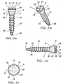
- an orthodontic mini-implant device in the form of a screw 2.
- the screw 2 is used to provide a point of anchorage in skeletal tissue for an orthodontic appliance.
- the screw 2 includes a head portion 4 having an upper end 6 and a lower end 8, and a body portion 10 having a screw thread 12 provided thereon.
- the body portion 10 extends from lower end 8 of head portion 4.
- Engagement means in the form of two slots 14, 16 are defined in upper end 6 and are provided substantially perpendicular to each other across substantially the entire width or diameter of the upper surface 6.
- Four quadrant pieces 18 are defined between slots 14, 16. The upper surface of these quadrant pieces comprise upper surface or end 6 of screw head 4.
- the slots 14, 16 are typically in the form of channels, with the upright part or depth of the channel located substantially longitudinally of the screw 2.
- the open end of the channel is substantially flush with upper end 6 of screw head 4 and the base of the channel is located a vertical distance below the upper end of the screw head.
- Recesses or undercuts 21 are defined internally of the screw head 4 below quadrant pieces 18 and above mid portion 22 of the screw head. Further recesses or undercuts 20 are provided around the outer perimeter of the screw head 4. Both recesses 21 and recesses 20 communicate with each other and with the channel slots 14, 16.
- recesses 21 are provided laterally of channels slots 14, 16 and substantially perpendicular to the depth of the channel.
- the base of recesses 21 is substantially continuous with the base of the channel slots.
- the recesses 21 and slots form an inverted 'T' formation. This provides a shoulder or hook-like portion for engagement of a part of an orthodontic appliance, such as for example a ligature wire, thereto.
- the screw head of the present invention can include both external and internal recesses or undercuts.
- the screw head of the present invention can provide internal recesses or undercuts only. Further attachment means can be provided with the screw head, such as one or more channels passing through middle section 22 of screw head 4 and/or the like.
- a lower portion 26 of screw head 4 has a narrowing taper towards lower end 8 of screw head 4.
- This taper is preferably at substantially a 45 degree angle (although the taper could be between approximately 45-70 degree angle) to improve the fit of the screw head against the bone surface in use.
- the screw thread 12 can take any suitable form and can be tapered if required along a part or, whole of the length thereof and/or on the width from the outer free edge to the body portion. In the illustrated embodiment the screw thread 12 is provided along substantially the entire length of body portion 10 but it will be appreciated that the screw thread could be provided along a part of the body portion only.
- Body portion 10 has a narrowing taper from end 8 to tip 28.
- a self tapping notch 30 is provided adjacent tip 28. This notch 30 extends longitudinally of body portion 10. The self tapping notch typically aids insertion of the screw in the patient's jaw.
- the tip 28 and the screw thread 12 is typically sharp enough and of such form to remove the requirement for drilling a pilot hole to allow insertion.
- the screw 2 can be formed from any suitable material but it is preferably that the material is titanium or a titanium alloy and further preferably grade 5 titanium alloy.
- FIG. 4a and 4b a further example of a mini implant 32 according to the present invention is illustrated. Similar features are shown using the same reference numerals as in figures 1-2 .
- Attachment means in the form of channels 34 are defined through middle section 22.
- the channels 34 typically pass from one side of middle section 22 to an opposite side.
- the attachment means allow wires, parts of orthodontic appliances and/or the like to be attached thereto.
- the pentagonal outer surface of the head and/or neck portion enables engagement with an insertion tool therewith.
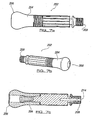
- FIG 3a there is illustrated apparatus for use in the method of positioning an implant in a patient's mouth or orthodontic cast of a patient's teeth.
- the apparatus includes a guidance cylinder 102 which allows the implant position and/ angulations to be transferred to the surgical placement position in a patient.
- the stent 302 that is formed using the apparatus, see figure 8 , allows access for both visual monitoring by the orthodontist and saline irrigation. It is particularly advantageous when the implant is being planned and inserted by different clinicians or when the orthodontist is inexperienced in implant techniques.
- a dental cast is typically made of the patient's teeth, such as for example a cast formed from Plaster of Paris TM .
- the clinician determines the position and angle of the implant in the patient's mouth.
- the three major parameters are considered in this positioning process; the topographical entry point, the anterior/posterior angle of entry and the vertical inclination of entry.
- This hole in the illustrated method is typically 9mm in depth.
- An analogue or dummy implant which is substantially of the same external dimensions and type as the actual mini-screw implant that is to be inserted in the patient's mouth, is inserted into the drilled cast hole.
- the analogue implant does not need to include the external or internal recesses if required.
- the analogue implant can be formed from any suitable material, such as for example, steel.
- Guidance cylinder or channel 102 is then fitted to the analogue implant and acts to increase the length of the analogue implant.
- an intermediate guidance attachment member 120 is attached to the top of the analogue screw head to increase the projection of the analogue implant device from the cast. This allows secure attachment of the guidance cylinder around the screw head, as shown in figure 3b .
- Intermediate attachment member 120 includes a base 122 which is substantially complementary in shape to external pentagonal surface of the analogue head and/or neck portion. The top 124 of member 120 is of such shape and dimensions to engage with an open end 108 of the guidance cylinder.
- the guidance cylinder includes first open end 108 and a second open end 110.
- An elongate body portion 112 is provided adjacent end 108 and this is slightly larger than or substantially equal to the size of the body portion of the analogue implant.
- a head portion 114 is provided adjacent end 110 and is slightly larger than the dimensions of the analogue implant head portion.
- the head portion 114 has a narrowing taper 116 at a lower end thereof and a raised or protruding portion 118 at end 110 thereof. More particularly, the guidance cylinder 102 is engaged over the top of the intermediate attachment member 120.
- Guidance cylinder 102 has an internal channel running longitudinally thereof.
- the diameter of this internal channel corresponds substantially to the diameter of the analogue implant or abutment and the external diameter of the insertion tool, such as a screw driver.
- the length of the internal channel, shown by arrow 106, is sufficient to allow the screw driver to positively engage within the cylinder.
- the guidance cylinder and/or intermediate attachment member can be formed from any suitable material and, in one example, is formed from metal.
- the cast with the analogue implant and guidance cylinder is then located in a vacuum forming machine with a suitable stent forming material or stent base plate.
- a blank mould or stent 302 is then made of the dental cast with the guidance cylinder in place.
- the stent When the stent is removed, it includes an impression of the user's teeth 304 with an elongate channel 306 provided at the required location and at the required angle necessary for insertion of the actual implant in the patient's mouth.
- the blank mould or stent 302 can be trimmed, such as on the labial and lingual edges.
- the stent 302 is then located over the patient's teeth in such a manner that the teeth indents 304 are aligned with the patient's actual teeth by a clinician.
- the implant of the present invention and the implant insertion drill or tool can be located through the elongate channel 306 of the stent to allow correct positioning in the patient's mouth.
- a bone punch may first need to be located through the stent channel to make an initial aperture or pilot hole at the site of location of the implant.
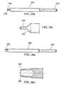
- Figures 7a-7c illustrate an example of a handle 204 of an insertion instrument 202 that can be used to insert the implant used in the present invention.
- the handle 204 has a first end 206 and a second end 208.
- Different screw driver or tool inserts can be detachably attached to second end 208.
- Examples of different tool inserts that can be used with insertion instrument 202 are shown in figures 5a-6b . More particularly, figures 5a and 5b illustrate a cortical bone punch insert 210 having a first end 212 for location in channel 214 defined in second end 208 of handle 202, and a second end 216 having a burr 218 located thereon for punching a recess in the bone.
- FIGS. 6a and 6b illustrate a tissue punch insert 220 having a first end 222 for location in channel 214 of handle 202, and a second end 224 having a recess or channel 226 defined therein (and provided substantially longitudinally of the insert 220) for punching a recess in a patient's mouth soft tissue.
- Figure 9 illustrates an alternative example of a stent forming kit.
- the kit includes an analogue implant 308 with external dimensions corresponding substantially to the external dimensions of the actual implant device to be located in the patient, a guidance cylinder 310 including an elongate cylindrical housing 312 with a channel 314 defined longitudinally thereof and an intermediate abutment member 316 with a cylindrical housing 318 and a pentagonal shaped inner channel or recess 320 at one end thereof to substantially correspond with the pentagonal outer surface of neck portion 322 of analogue implant 308 to allow engagement therewith.
- the outer dimensions of the abutment member 316 are slightly smaller than the dimensions of channel 314, thereby allowing the guidance cylinder to be located over at least part of abutment member 316 to elongate the analogue implant to allow the stent to be formed with a protruding channel portion.
Landscapes
- Health & Medical Sciences (AREA)
- Oral & Maxillofacial Surgery (AREA)
- Orthopedic Medicine & Surgery (AREA)
- Dentistry (AREA)
- Epidemiology (AREA)
- Life Sciences & Earth Sciences (AREA)
- Animal Behavior & Ethology (AREA)
- General Health & Medical Sciences (AREA)
- Public Health (AREA)
- Veterinary Medicine (AREA)
- Dental Prosthetics (AREA)
- Dental Tools And Instruments Or Auxiliary Dental Instruments (AREA)
Claims (14)
- Kieferorthopädische Implantatvorrichtung, welche aufweist einen Kopfbereich; ein Eingriffsmittel, um es einem Einbringinstrument zu erlauben, bei der Benutzung damit in Eingriff gebracht zu werden; einen Körperbereich, welcher sich von einer unteren Oberfläche des Kopfbereichs erstreckt; wobei das Eingriffsmittel umfasst: einen oder mehrere Schlitze, welche in einer oberen Oberfläche des Kopfbereichs definiert sind, wobei der eine oder die mehreren Schlitze in der Form eines Kanals mit einem offenen Ende, einer Basis und Seitenwänden ausgebildet sind; wobei zumindest ein Rücksprung oder Hinterschnitt im Wesentlichen im Inneren des Kopfbereichs vorgesehen ist, um einen Befestigungspunkt für zumindest einen Teil einer kieferchirurgischen Vorrichtung daran bereitzustellen, dadurch gekennzeichnet, dass der zumindest eine Rücksprung oder Hinterschnitt in einer Seitenwand oder -wänden des Kanals definiert ist und lateral des Kanals im Wesentlichen rechtwinklig zu den Seitenwänden vorgesehen ist.
- Vorrichtung nach Anspruch 1, wobei zwei Schlitze auf der oberen Oberfläche des Kopfbereichs bereitgestellt und angeordnet sind, um ein Kreuz zu formen.
- Vorrichtung nach Anspruch 1, wobei die Vorrichtung in der Form einer Schraube ist und zumindest ein Teil des Körperbereichs mit einem Schraubengewinde versehen ist.
- Vorrichtung nach Anspruch 1, wobei der Teil der kieferchirurgischen Vorrichtung ein Draht, ein Band, ein Gummi oder ein elastisches Element, eine Ligatur oder ein Zugelement ist.
- Vorrichtung nach Anspruch 1, wobei der im Wesentlichen innere Rücksprung oder Hinterschnitt mit einem weiteren Rücksprung oder Hinterschnitt in Verbindung steht, welcher um zumindest einen Teil einer äußeren Kante oder Seitenwand des Kopfbereichs vorgesehen ist.
- Vorrichtung nach Anspruch 5, wobei der weitere Rücksprung oder Hinterschnitt im Wesentlichen rechtwinklig zur äußeren Seitenwand des Kopfbereichs vorgesehen ist.
- Vorrichtung nach Anspruch 1, wobei Befestigungsmittel auf dem Kopfbereich vorgesehen sind und wobei die Befestigungsmittel unter einer oberen Oberfläche des Kopfbereichs vorgesehen sind.
- Vorrichtung nach Anspruch 7, wobei das Befestigungsmittel eine oder mehrere Öffnungen, Schlitze oder Kanäle umfasst.
- Vorrichtung nach Anspruch 1, wobei die Vorrichtung selbstbohrend ist und ein Ende der Vorrichtung ausreichend scharf ist, um das Eindringen in einen Knochen zu erlauben.
- Vorrichtung nach Anspruch 1, wobei ein selbstgewindeschneidender Einschnitt an dem Körperbereich vorgesehen ist.
- Vorrichtung nach Anspruch 10, wobei die Länge des selbstgewindeschneidenden Einschnitts im Wesentlichen longitudinal der Vorrichtung vorgesehen ist.
- Vorrichtung nach Anspruch 1, wobei ein unterer Teil des Kopfbereichs oder Halsbereichs mit sich verjüngenden Neigung in Richtung des Körperbereichs versehen ist.
- Vorrichtung nach Anspruch 12, wobei die sich verjüngende Neigung einen Winkel von 45° bis 70° aufweist.
- Vorrichtung nach Anspruch 1, wobei der Kopfbereich einen Halsbereich umfasst und die Verbindungsmittel mit dem Halsbereich verbunden sind und wobei die Verbindungsmittel vorzugsweise mit einer pentagonalen Oberfläche des Halsbereichs verbunden sind.
Priority Applications (1)
| Application Number | Priority Date | Filing Date | Title |
|---|---|---|---|
| EP09000254A EP2052692A3 (de) | 2006-04-25 | 2007-04-05 | Orthodontische Implantatsvorrichtung |
Applications Claiming Priority (2)
| Application Number | Priority Date | Filing Date | Title |
|---|---|---|---|
| US74553806P | 2006-04-25 | 2006-04-25 | |
| PCT/GB2007/001265 WO2007128969A2 (en) | 2006-04-25 | 2007-04-05 | Orthodontic implant device |
Related Child Applications (2)
| Application Number | Title | Priority Date | Filing Date |
|---|---|---|---|
| EP09000254A Division EP2052692A3 (de) | 2006-04-25 | 2007-04-05 | Orthodontische Implantatsvorrichtung |
| EP09000254A Division-Into EP2052692A3 (de) | 2006-04-25 | 2007-04-05 | Orthodontische Implantatsvorrichtung |
Publications (2)
| Publication Number | Publication Date |
|---|---|
| EP2010094A2 EP2010094A2 (de) | 2009-01-07 |
| EP2010094B1 true EP2010094B1 (de) | 2015-07-22 |
Family
ID=38566071
Family Applications (2)
| Application Number | Title | Priority Date | Filing Date |
|---|---|---|---|
| EP09000254A Withdrawn EP2052692A3 (de) | 2006-04-25 | 2007-04-05 | Orthodontische Implantatsvorrichtung |
| EP07732310.3A Active EP2010094B1 (de) | 2006-04-25 | 2007-04-05 | Kieferorthopädische implantatvorrichtung |
Family Applications Before (1)
| Application Number | Title | Priority Date | Filing Date |
|---|---|---|---|
| EP09000254A Withdrawn EP2052692A3 (de) | 2006-04-25 | 2007-04-05 | Orthodontische Implantatsvorrichtung |
Country Status (3)
| Country | Link |
|---|---|
| US (1) | US20100003634A1 (de) |
| EP (2) | EP2052692A3 (de) |
| WO (1) | WO2007128969A2 (de) |
Families Citing this family (10)
| Publication number | Priority date | Publication date | Assignee | Title |
|---|---|---|---|---|
| CA2704284A1 (en) | 2007-08-30 | 2009-03-12 | Vertex Pharmaceuticals Incorporated | Co-crystals and pharmaceutical compositions comprising the same |
| US20090220914A1 (en) * | 2008-02-28 | 2009-09-03 | Dental- Li Uri Consulting 2007 Ltd. | Dental implant and a method of implantation thereof |
| JP2011517603A (ja) | 2008-04-09 | 2011-06-16 | スリーエム イノベイティブ プロパティズ カンパニー | 取り外し可能な部分を備えた舌側歯科矯正装具 |
| TWM360687U (en) * | 2008-07-10 | 2009-07-11 | nai-chang Yu | Orthodontic temporary anchorage device |
| IT1392605B1 (it) * | 2008-12-31 | 2012-03-09 | Hdc S R L | Dispositivo di fissaggio per apparecchi ortodontici |
| DE102009050049B4 (de) * | 2009-10-21 | 2012-06-21 | Sören-Michael Usslepp | Einteilige und zweiteilige Zahnersatz-Implantate, mit wellenförmigem Außengewinde und für zweiteilige Implantate, ein auf zwei Positionsvorgaben limitiertes Ankopplungsdesign, für prothetische Bau- und Hilfsteile inkl. derer Tiefen- bzw. Höhenmarkierung |
| IT1400805B1 (it) * | 2010-07-02 | 2013-07-02 | Vigolo | Vite di ancoraggio ortodontico e procedimento per la sua realizzazione |
| ES2775427T3 (es) * | 2014-09-19 | 2020-07-27 | Cendres Metaux Sa | Instrumento para la manipulación de una pieza dental |
| US10779912B2 (en) | 2014-12-19 | 2020-09-22 | Paul Hertz | Dental implant system |
| JP6185130B1 (ja) * | 2016-09-10 | 2017-08-23 | 医療法人クリエイティングスマイルズ | 歯列矯正用インプラント装置 |
Family Cites Families (27)
| Publication number | Priority date | Publication date | Assignee | Title |
|---|---|---|---|---|
| US2684094A (en) * | 1951-06-21 | 1954-07-20 | Lissy John | Nonslip screw driver and screwhead |
| US2792039A (en) * | 1954-12-14 | 1957-05-14 | Hi Shear Rivet Tool Company | Slotted screw head and driver therefor having non-burring engagement |
| US4130152A (en) * | 1977-10-19 | 1978-12-19 | John Sawyer | Slot-head fastener and driver therefor |
| US5133660A (en) * | 1989-08-07 | 1992-07-28 | Fenick Thomas J | Device for locating the optimum position for a tooth implant |
| WO1994017961A1 (en) * | 1993-02-10 | 1994-08-18 | Marvin Bassell | Fastener and driving tool |
| JP2620823B2 (ja) * | 1993-05-11 | 1997-06-18 | ジンテーズ アクチエンゲゼルシャフト,クール | 接骨固定部品およびその操作装置 |
| US5556278A (en) * | 1994-09-07 | 1996-09-17 | Meitner; Sean W. | Method for making and using a template for a dental implant osteotomy and components relating thereto |
| US5613852A (en) * | 1995-01-06 | 1997-03-25 | Board Of Regents Univ Of Ne At Lincoln | Dental implant drill guide system |
| IL118371A (en) * | 1996-05-22 | 2000-06-29 | Conley Roy | Drill guide |
| AU731976B2 (en) * | 1997-06-02 | 2001-04-12 | Jeannette M. D. Martello | Soft tissue securing anchor |
| IT1307114B1 (it) * | 1999-11-26 | 2001-10-23 | Nicos Sas Di De Toni Nicoletta | Vite di ancoraggio per trattamenti di correzione ortodontica. |
| US6440136B1 (en) * | 2000-05-24 | 2002-08-27 | Medtronic Ps Medical, Inc. | Apparatus for attaching to bone |
| KR200207524Y1 (ko) * | 2000-07-12 | 2000-12-15 | 박영철 | 교정틀 고정구 |
| KR200233786Y1 (ko) * | 2001-03-07 | 2001-09-26 | 박효상 | 치열 교정용 스크류 |
| DE10132088B4 (de) * | 2001-07-05 | 2005-09-29 | Altatec Medizintechnische Elemente Gmbh & Co. Kg | Kieferorthopädisches Implantatsystem zur Zahnmobilisierung |
| US6869282B2 (en) * | 2002-03-04 | 2005-03-22 | Robert P. Carmichael | Implant positioning device and method |
| US20050095550A1 (en) * | 2002-06-27 | 2005-05-05 | Jung-Moon Kim | Orthodontic implant |
| KR100430770B1 (ko) * | 2002-06-27 | 2004-05-17 | 박영철 | 임플랜트 |
| US7125250B2 (en) * | 2003-02-07 | 2006-10-24 | Cheng-Yi Lin | Screw device for orthodontic treatment |
| US7172416B2 (en) * | 2003-12-11 | 2007-02-06 | Cheng-Yi Lin | Screw device for orthodontic treatment |
| US7101177B2 (en) * | 2002-08-05 | 2006-09-05 | Cheng-Yi Lin | Screw device for orthodontic treatment |
| KR20050044214A (ko) * | 2003-11-07 | 2005-05-12 | 경희문 | 브라켓 헤드 타입의 치열 교정용 스크류 |
| US20070083206A1 (en) * | 2005-09-21 | 2007-04-12 | Microware Precision Co., Ltd. | Self drilling and tapping bone screw |
| US20070122764A1 (en) * | 2005-11-28 | 2007-05-31 | Ace Surgical Supply Co., Inc. | Orthodontic bone screw |
| DE102008006094B4 (de) * | 2007-02-14 | 2014-05-08 | Bernhard Förster Gmbh | Orthodontisches Schraubimplantat sowie System aus orthodontischem Schraubimplantat und Drahtbogen |
| DE102007045199B3 (de) * | 2007-09-21 | 2008-12-04 | Bernhard Förster Gmbh | Orthodontisches Implantatsystem |
| US7780444B1 (en) * | 2008-01-07 | 2010-08-24 | Veris Medical, Inc. | Orthodontic anchor |
-
2007
- 2007-04-05 US US12/298,408 patent/US20100003634A1/en not_active Abandoned
- 2007-04-05 EP EP09000254A patent/EP2052692A3/de not_active Withdrawn
- 2007-04-05 EP EP07732310.3A patent/EP2010094B1/de active Active
- 2007-04-05 WO PCT/GB2007/001265 patent/WO2007128969A2/en active Application Filing
Also Published As
| Publication number | Publication date |
|---|---|
| EP2052692A2 (de) | 2009-04-29 |
| EP2052692A3 (de) | 2009-05-13 |
| US20100003634A1 (en) | 2010-01-07 |
| WO2007128969A3 (en) | 2008-02-28 |
| EP2010094A2 (de) | 2009-01-07 |
| WO2007128969A2 (en) | 2007-11-15 |
Similar Documents
| Publication | Publication Date | Title |
|---|---|---|
| EP2010094B1 (de) | Kieferorthopädische implantatvorrichtung | |
| JP6768861B2 (ja) | 顎矯正インプラント | |
| US7153132B2 (en) | Mini-dental implant surgical stent | |
| EP3415112B1 (de) | Verfahren zur virtuellen entwicklung einer chirurgischen führung für zahnimplantate | |
| US7845943B2 (en) | Method for making and using a template for locating a dental implant and components relating thereto | |
| JP5669929B2 (ja) | 顎矯正インプラント及びその使用方法 | |
| US8858228B2 (en) | Method and kit for dental implant drilling guides | |
| US8535055B2 (en) | Method and kit for producing dental implant drilling guides | |
| US8021150B2 (en) | Method for dental implant placement | |
| US20100297574A1 (en) | CT-based, Side-loading Surgical and Laboratory Dental Implant Guide System and Methodology of Use | |
| JP2016517334A (ja) | 歯科インプラントを実施するための精密手術用ガイダンスツールシステムおよび提供方法 | |
| JP7450845B2 (ja) | 位置合わせ部材を有する外科用ガイド及びインプラント | |
| US20100092912A1 (en) | Guide tube and guide tube positioning device | |
| KR101763763B1 (ko) | 임플란트 식립위치 가이드기구 | |
| EP0256708A2 (de) | Verfahren und Vorrichtung zum Herstellen einer Zahnprothese sowie ihre Befestigung im Mund eines Patienten | |
| US20140272793A1 (en) | Dental implant instrumentation and methods | |
| US20210282894A1 (en) | Drill jig for an oral surgery intervention | |
| EP3597140A1 (de) | Modulare schablone zum bohren von löchern und verfahren zur herstellung davon | |
| EP2842514B1 (de) | Verfahren zur positionierung eines führungsrohrs in einer platte aus einem polymermaterial, tomografischer referenzträger und vorrichtung zur positionierung eines führungsrohrs | |
| US11559373B2 (en) | Stable winged affixation system for guided dental implantation | |
| KR20190059556A (ko) | 임플란트 핸드피스 | |
| US11617631B2 (en) | Surgical guide tool for single dental implant positioning | |
| KR102555871B1 (ko) | 임플란트 시술용 게이지 | |
| EP3847993B1 (de) | Stabiles befestigungssystem für geführte zahnimplantation | |
| WO2013138308A1 (en) | Method and kit for dental implant drilling guides |
Legal Events
| Date | Code | Title | Description |
|---|---|---|---|
| PUAI | Public reference made under article 153(3) epc to a published international application that has entered the european phase |
Free format text: ORIGINAL CODE: 0009012 |
|
| 17P | Request for examination filed |
Effective date: 20081020 |
|
| AK | Designated contracting states |
Kind code of ref document: A2 Designated state(s): AT BE BG CH CY CZ DE DK EE ES FI FR GB GR HU IE IS IT LI LT LU LV MC MT NL PL PT RO SE SI SK TR |
|
| AX | Request for extension of the european patent |
Extension state: AL BA HR MK RS |
|
| RAP1 | Party data changed (applicant data changed or rights of an application transferred) |
Owner name: D B ORTHODONTICS LTD Owner name: COUSLEY, RICHARD |
|
| DAX | Request for extension of the european patent (deleted) | ||
| 17Q | First examination report despatched |
Effective date: 20110722 |
|
| GRAP | Despatch of communication of intention to grant a patent |
Free format text: ORIGINAL CODE: EPIDOSNIGR1 |
|
| INTG | Intention to grant announced |
Effective date: 20131205 |
|
| GRAP | Despatch of communication of intention to grant a patent |
Free format text: ORIGINAL CODE: EPIDOSNIGR1 |
|
| INTG | Intention to grant announced |
Effective date: 20150204 |
|
| GRAS | Grant fee paid |
Free format text: ORIGINAL CODE: EPIDOSNIGR3 |
|
| GRAA | (expected) grant |
Free format text: ORIGINAL CODE: 0009210 |
|
| AK | Designated contracting states |
Kind code of ref document: B1 Designated state(s): AT BE BG CH CY CZ DE DK EE ES FI FR GB GR HU IE IS IT LI LT LU LV MC MT NL PL PT RO SE SI SK TR |
|
| REG | Reference to a national code |
Ref country code: GB Ref legal event code: FG4D |
|
| REG | Reference to a national code |
Ref country code: CH Ref legal event code: EP |
|
| REG | Reference to a national code |
Ref country code: IE Ref legal event code: FG4D |
|
| REG | Reference to a national code |
Ref country code: AT Ref legal event code: REF Ref document number: 737428 Country of ref document: AT Kind code of ref document: T Effective date: 20150815 |
|
| REG | Reference to a national code |
Ref country code: DE Ref legal event code: R096 Ref document number: 602007042239 Country of ref document: DE |
|
| REG | Reference to a national code |
Ref country code: AT Ref legal event code: MK05 Ref document number: 737428 Country of ref document: AT Kind code of ref document: T Effective date: 20150722 |
|
| REG | Reference to a national code |
Ref country code: LT Ref legal event code: MG4D |
|
| REG | Reference to a national code |
Ref country code: NL Ref legal event code: MP Effective date: 20150722 |
|
| PG25 | Lapsed in a contracting state [announced via postgrant information from national office to epo] |
Ref country code: GR Free format text: LAPSE BECAUSE OF FAILURE TO SUBMIT A TRANSLATION OF THE DESCRIPTION OR TO PAY THE FEE WITHIN THE PRESCRIBED TIME-LIMIT Effective date: 20151023 Ref country code: LV Free format text: LAPSE BECAUSE OF FAILURE TO SUBMIT A TRANSLATION OF THE DESCRIPTION OR TO PAY THE FEE WITHIN THE PRESCRIBED TIME-LIMIT Effective date: 20150722 Ref country code: FI Free format text: LAPSE BECAUSE OF FAILURE TO SUBMIT A TRANSLATION OF THE DESCRIPTION OR TO PAY THE FEE WITHIN THE PRESCRIBED TIME-LIMIT Effective date: 20150722 Ref country code: LT Free format text: LAPSE BECAUSE OF FAILURE TO SUBMIT A TRANSLATION OF THE DESCRIPTION OR TO PAY THE FEE WITHIN THE PRESCRIBED TIME-LIMIT Effective date: 20150722 |
|
| PG25 | Lapsed in a contracting state [announced via postgrant information from national office to epo] |
Ref country code: PT Free format text: LAPSE BECAUSE OF FAILURE TO SUBMIT A TRANSLATION OF THE DESCRIPTION OR TO PAY THE FEE WITHIN THE PRESCRIBED TIME-LIMIT Effective date: 20151123 Ref country code: SE Free format text: LAPSE BECAUSE OF FAILURE TO SUBMIT A TRANSLATION OF THE DESCRIPTION OR TO PAY THE FEE WITHIN THE PRESCRIBED TIME-LIMIT Effective date: 20150722 Ref country code: ES Free format text: LAPSE BECAUSE OF FAILURE TO SUBMIT A TRANSLATION OF THE DESCRIPTION OR TO PAY THE FEE WITHIN THE PRESCRIBED TIME-LIMIT Effective date: 20150722 Ref country code: PL Free format text: LAPSE BECAUSE OF FAILURE TO SUBMIT A TRANSLATION OF THE DESCRIPTION OR TO PAY THE FEE WITHIN THE PRESCRIBED TIME-LIMIT Effective date: 20150722 Ref country code: AT Free format text: LAPSE BECAUSE OF FAILURE TO SUBMIT A TRANSLATION OF THE DESCRIPTION OR TO PAY THE FEE WITHIN THE PRESCRIBED TIME-LIMIT Effective date: 20150722 Ref country code: IS Free format text: LAPSE BECAUSE OF FAILURE TO SUBMIT A TRANSLATION OF THE DESCRIPTION OR TO PAY THE FEE WITHIN THE PRESCRIBED TIME-LIMIT Effective date: 20151122 |
|
| REG | Reference to a national code |
Ref country code: DE Ref legal event code: R097 Ref document number: 602007042239 Country of ref document: DE |
|
| PG25 | Lapsed in a contracting state [announced via postgrant information from national office to epo] |
Ref country code: EE Free format text: LAPSE BECAUSE OF FAILURE TO SUBMIT A TRANSLATION OF THE DESCRIPTION OR TO PAY THE FEE WITHIN THE PRESCRIBED TIME-LIMIT Effective date: 20150722 Ref country code: SK Free format text: LAPSE BECAUSE OF FAILURE TO SUBMIT A TRANSLATION OF THE DESCRIPTION OR TO PAY THE FEE WITHIN THE PRESCRIBED TIME-LIMIT Effective date: 20150722 Ref country code: CZ Free format text: LAPSE BECAUSE OF FAILURE TO SUBMIT A TRANSLATION OF THE DESCRIPTION OR TO PAY THE FEE WITHIN THE PRESCRIBED TIME-LIMIT Effective date: 20150722 Ref country code: IT Free format text: LAPSE BECAUSE OF FAILURE TO SUBMIT A TRANSLATION OF THE DESCRIPTION OR TO PAY THE FEE WITHIN THE PRESCRIBED TIME-LIMIT Effective date: 20150722 Ref country code: DK Free format text: LAPSE BECAUSE OF FAILURE TO SUBMIT A TRANSLATION OF THE DESCRIPTION OR TO PAY THE FEE WITHIN THE PRESCRIBED TIME-LIMIT Effective date: 20150722 |
|
| PLBE | No opposition filed within time limit |
Free format text: ORIGINAL CODE: 0009261 |
|
| STAA | Information on the status of an ep patent application or granted ep patent |
Free format text: STATUS: NO OPPOSITION FILED WITHIN TIME LIMIT |
|
| PG25 | Lapsed in a contracting state [announced via postgrant information from national office to epo] |
Ref country code: RO Free format text: LAPSE BECAUSE OF FAILURE TO SUBMIT A TRANSLATION OF THE DESCRIPTION OR TO PAY THE FEE WITHIN THE PRESCRIBED TIME-LIMIT Effective date: 20150722 |
|
| 26N | No opposition filed |
Effective date: 20160425 |
|
| PG25 | Lapsed in a contracting state [announced via postgrant information from national office to epo] |
Ref country code: SI Free format text: LAPSE BECAUSE OF FAILURE TO SUBMIT A TRANSLATION OF THE DESCRIPTION OR TO PAY THE FEE WITHIN THE PRESCRIBED TIME-LIMIT Effective date: 20150722 Ref country code: BE Free format text: LAPSE BECAUSE OF NON-PAYMENT OF DUE FEES Effective date: 20160430 |
|
| REG | Reference to a national code |
Ref country code: CH Ref legal event code: PL |
|
| PG25 | Lapsed in a contracting state [announced via postgrant information from national office to epo] |
Ref country code: LU Free format text: LAPSE BECAUSE OF FAILURE TO SUBMIT A TRANSLATION OF THE DESCRIPTION OR TO PAY THE FEE WITHIN THE PRESCRIBED TIME-LIMIT Effective date: 20160405 Ref country code: BE Free format text: LAPSE BECAUSE OF FAILURE TO SUBMIT A TRANSLATION OF THE DESCRIPTION OR TO PAY THE FEE WITHIN THE PRESCRIBED TIME-LIMIT Effective date: 20150722 |
|
| REG | Reference to a national code |
Ref country code: IE Ref legal event code: MM4A |
|
| REG | Reference to a national code |
Ref country code: FR Ref legal event code: ST Effective date: 20161230 |
|
| PG25 | Lapsed in a contracting state [announced via postgrant information from national office to epo] |
Ref country code: FR Free format text: LAPSE BECAUSE OF NON-PAYMENT OF DUE FEES Effective date: 20160502 Ref country code: CH Free format text: LAPSE BECAUSE OF NON-PAYMENT OF DUE FEES Effective date: 20160430 Ref country code: LI Free format text: LAPSE BECAUSE OF NON-PAYMENT OF DUE FEES Effective date: 20160430 |
|
| PG25 | Lapsed in a contracting state [announced via postgrant information from national office to epo] |
Ref country code: IE Free format text: LAPSE BECAUSE OF NON-PAYMENT OF DUE FEES Effective date: 20160405 |
|
| PG25 | Lapsed in a contracting state [announced via postgrant information from national office to epo] |
Ref country code: NL Free format text: LAPSE BECAUSE OF FAILURE TO SUBMIT A TRANSLATION OF THE DESCRIPTION OR TO PAY THE FEE WITHIN THE PRESCRIBED TIME-LIMIT Effective date: 20150722 |
|
| PG25 | Lapsed in a contracting state [announced via postgrant information from national office to epo] |
Ref country code: CY Free format text: LAPSE BECAUSE OF FAILURE TO SUBMIT A TRANSLATION OF THE DESCRIPTION OR TO PAY THE FEE WITHIN THE PRESCRIBED TIME-LIMIT Effective date: 20150722 Ref country code: HU Free format text: LAPSE BECAUSE OF FAILURE TO SUBMIT A TRANSLATION OF THE DESCRIPTION OR TO PAY THE FEE WITHIN THE PRESCRIBED TIME-LIMIT; INVALID AB INITIO Effective date: 20070405 |
|
| PG25 | Lapsed in a contracting state [announced via postgrant information from national office to epo] |
Ref country code: TR Free format text: LAPSE BECAUSE OF FAILURE TO SUBMIT A TRANSLATION OF THE DESCRIPTION OR TO PAY THE FEE WITHIN THE PRESCRIBED TIME-LIMIT Effective date: 20150722 Ref country code: MT Free format text: LAPSE BECAUSE OF NON-PAYMENT OF DUE FEES Effective date: 20160430 Ref country code: MC Free format text: LAPSE BECAUSE OF FAILURE TO SUBMIT A TRANSLATION OF THE DESCRIPTION OR TO PAY THE FEE WITHIN THE PRESCRIBED TIME-LIMIT Effective date: 20150722 |
|
| PG25 | Lapsed in a contracting state [announced via postgrant information from national office to epo] |
Ref country code: BG Free format text: LAPSE BECAUSE OF FAILURE TO SUBMIT A TRANSLATION OF THE DESCRIPTION OR TO PAY THE FEE WITHIN THE PRESCRIBED TIME-LIMIT Effective date: 20150722 |
|
| P01 | Opt-out of the competence of the unified patent court (upc) registered |
Effective date: 20230525 |
|
| PGFP | Annual fee paid to national office [announced via postgrant information from national office to epo] |
Ref country code: GB Payment date: 20240429 Year of fee payment: 18 |
|
| PGFP | Annual fee paid to national office [announced via postgrant information from national office to epo] |
Ref country code: DE Payment date: 20240417 Year of fee payment: 18 |