EP2009252B1 - Montage einer Welle in einem Wellenlager mit selbstabziehender Mutter - Google Patents
Montage einer Welle in einem Wellenlager mit selbstabziehender Mutter Download PDFInfo
- Publication number
- EP2009252B1 EP2009252B1 EP08158908A EP08158908A EP2009252B1 EP 2009252 B1 EP2009252 B1 EP 2009252B1 EP 08158908 A EP08158908 A EP 08158908A EP 08158908 A EP08158908 A EP 08158908A EP 2009252 B1 EP2009252 B1 EP 2009252B1
- Authority
- EP
- European Patent Office
- Prior art keywords
- nut
- trunnion
- engine
- coupling
- axial
- Prior art date
- Legal status (The legal status is an assumption and is not a legal conclusion. Google has not performed a legal analysis and makes no representation as to the accuracy of the status listed.)
- Active
Links
Images


Classifications
-
- F—MECHANICAL ENGINEERING; LIGHTING; HEATING; WEAPONS; BLASTING
- F01—MACHINES OR ENGINES IN GENERAL; ENGINE PLANTS IN GENERAL; STEAM ENGINES
- F01D—NON-POSITIVE DISPLACEMENT MACHINES OR ENGINES, e.g. STEAM TURBINES
- F01D25/00—Component parts, details, or accessories, not provided for in, or of interest apart from, other groups
- F01D25/16—Arrangement of bearings; Supporting or mounting bearings in casings
- F01D25/162—Bearing supports
-
- F—MECHANICAL ENGINEERING; LIGHTING; HEATING; WEAPONS; BLASTING
- F16—ENGINEERING ELEMENTS AND UNITS; GENERAL MEASURES FOR PRODUCING AND MAINTAINING EFFECTIVE FUNCTIONING OF MACHINES OR INSTALLATIONS; THERMAL INSULATION IN GENERAL
- F16D—COUPLINGS FOR TRANSMITTING ROTATION; CLUTCHES; BRAKES
- F16D1/00—Couplings for rigidly connecting two coaxial shafts or other movable machine elements
- F16D1/06—Couplings for rigidly connecting two coaxial shafts or other movable machine elements for attachment of a member on a shaft or on a shaft-end
-
- F—MECHANICAL ENGINEERING; LIGHTING; HEATING; WEAPONS; BLASTING
- F05—INDEXING SCHEMES RELATING TO ENGINES OR PUMPS IN VARIOUS SUBCLASSES OF CLASSES F01-F04
- F05B—INDEXING SCHEME RELATING TO WIND, SPRING, WEIGHT, INERTIA OR LIKE MOTORS, TO MACHINES OR ENGINES FOR LIQUIDS COVERED BY SUBCLASSES F03B, F03D AND F03G
- F05B2260/00—Function
- F05B2260/30—Retaining components in desired mutual position
- F05B2260/301—Retaining bolts or nuts
-
- F—MECHANICAL ENGINEERING; LIGHTING; HEATING; WEAPONS; BLASTING
- F05—INDEXING SCHEMES RELATING TO ENGINES OR PUMPS IN VARIOUS SUBCLASSES OF CLASSES F01-F04
- F05D—INDEXING SCHEME FOR ASPECTS RELATING TO NON-POSITIVE-DISPLACEMENT MACHINES OR ENGINES, GAS-TURBINES OR JET-PROPULSION PLANTS
- F05D2230/00—Manufacture
- F05D2230/60—Assembly methods
- F05D2230/68—Assembly methods using auxiliary equipment for lifting or holding
-
- F—MECHANICAL ENGINEERING; LIGHTING; HEATING; WEAPONS; BLASTING
- F05—INDEXING SCHEMES RELATING TO ENGINES OR PUMPS IN VARIOUS SUBCLASSES OF CLASSES F01-F04
- F05D—INDEXING SCHEME FOR ASPECTS RELATING TO NON-POSITIVE-DISPLACEMENT MACHINES OR ENGINES, GAS-TURBINES OR JET-PROPULSION PLANTS
- F05D2230/00—Manufacture
- F05D2230/70—Disassembly methods
-
- F—MECHANICAL ENGINEERING; LIGHTING; HEATING; WEAPONS; BLASTING
- F05—INDEXING SCHEMES RELATING TO ENGINES OR PUMPS IN VARIOUS SUBCLASSES OF CLASSES F01-F04
- F05D—INDEXING SCHEME FOR ASPECTS RELATING TO NON-POSITIVE-DISPLACEMENT MACHINES OR ENGINES, GAS-TURBINES OR JET-PROPULSION PLANTS
- F05D2260/00—Function
- F05D2260/40—Transmission of power
- F05D2260/403—Transmission of power through the shape of the drive components
- F05D2260/4031—Transmission of power through the shape of the drive components as in toothed gearing
-
- Y—GENERAL TAGGING OF NEW TECHNOLOGICAL DEVELOPMENTS; GENERAL TAGGING OF CROSS-SECTIONAL TECHNOLOGIES SPANNING OVER SEVERAL SECTIONS OF THE IPC; TECHNICAL SUBJECTS COVERED BY FORMER USPC CROSS-REFERENCE ART COLLECTIONS [XRACs] AND DIGESTS
- Y10—TECHNICAL SUBJECTS COVERED BY FORMER USPC
- Y10T—TECHNICAL SUBJECTS COVERED BY FORMER US CLASSIFICATION
- Y10T29/00—Metal working
- Y10T29/49—Method of mechanical manufacture
- Y10T29/49636—Process for making bearing or component thereof
- Y10T29/49696—Mounting
-
- Y—GENERAL TAGGING OF NEW TECHNOLOGICAL DEVELOPMENTS; GENERAL TAGGING OF CROSS-SECTIONAL TECHNOLOGIES SPANNING OVER SEVERAL SECTIONS OF THE IPC; TECHNICAL SUBJECTS COVERED BY FORMER USPC CROSS-REFERENCE ART COLLECTIONS [XRACs] AND DIGESTS
- Y10—TECHNICAL SUBJECTS COVERED BY FORMER USPC
- Y10T—TECHNICAL SUBJECTS COVERED BY FORMER US CLASSIFICATION
- Y10T403/00—Joints and connections
- Y10T403/16—Joints and connections with adjunctive protector, broken parts retainer, repair, assembly or disassembly feature
- Y10T403/1608—Holding means or protector functioning only during transportation, assembly or disassembly
-
- Y—GENERAL TAGGING OF NEW TECHNOLOGICAL DEVELOPMENTS; GENERAL TAGGING OF CROSS-SECTIONAL TECHNOLOGIES SPANNING OVER SEVERAL SECTIONS OF THE IPC; TECHNICAL SUBJECTS COVERED BY FORMER USPC CROSS-REFERENCE ART COLLECTIONS [XRACs] AND DIGESTS
- Y10—TECHNICAL SUBJECTS COVERED BY FORMER USPC
- Y10T—TECHNICAL SUBJECTS COVERED BY FORMER US CLASSIFICATION
- Y10T403/00—Joints and connections
- Y10T403/70—Interfitted members
- Y10T403/7009—Rotary binding cam or wedge
- Y10T403/7011—Radially interposed shim or bushing
Definitions
- the present invention relates to a gas turbine engine in the aeronautical field, and is intended for mounting a shaft inside the engine, more particularly at the upstream end of the high-pressure compressor shaft in an engine. double body.
- intermediate casing designates the element of the structural stator behind the fan casing through which part of the forces between the engine and the aircraft pass and which supports the front bearings of the rotors.
- the intermediate casing comprises a hub arranged to support bearings including the front bearing of the rotor shaft at high pressure.
- the hub is connected to an outer shell by radial arms that pass through the primary and secondary flows.
- the HP compressor bearing rotatably supports the front end of the HP compressor shaft.
- In front of this shaft in its axial extension, is mounted a conical pinion which meshes with a conical pinion integral with a radial shaft.
- These sprockets together form the IGB (Intermediate GearBox).
- the radial shaft drives at its radially outer end, on the casing of the blower, the gears of the box, called AGB (Accessories GearBox), mechanical drive of the auxiliary equipment of the engine: pumps, generators of electric current or others.
- the elements of the bearing are arranged to allow mounting from the rear. Such a solution is advantageous but requires precautions.
- a known solution on a dual-flow, dual-body engine uses a complex, many-piece system that is difficult to manufacture and install. This solution also requires a great deal of length for installation incompatible with small motors.
- the problem to solve therefore concerns a type of connection between the HP compressor shaft, the IGB and the bearing allowing the assembly and disassembly of HP compressor with single access tools from the rear of the engine.
- the invention also aims a compact connection that fits into the available space without the need to modify the surrounding parts or reduce the clearance with the low pressure turbine shaft. Such clearance is necessary in case of decoupling of the bearings of the fan during a dawn loss, for example, and for engine ventilation.
- the invention relates to a gas turbine engine comprising a shaft, a bearing, a sleeve supported by the bearing, the shaft being engaged by an end journal inside the sleeve and fixed to the sleeve by means of a cylindrical nut.
- the nut is housed inside the trunnion and is in axial abutment in a first direction against the sleeve, when the pin is screwed onto the nut, a split stop ring housed in an annular groove formed on the outer face of the nut axial stop against the sleeve in the opposite direction to the first allowing the extraction of the sleeve journal by unscrewing the nut.
- the nut is therefore of the self extracting type and makes it possible to simplify the disassembly assembly sequence of the motor.
- the engine parts are indeed part of the tools required for this sequence.
- the engine therefore permanently integrates the most critical part of this tool which simplifies the rest of the tooling that must be available in each maintenance shop.
- its thickness is less than the radial space between the nut and the sleeve.
- the surface of the split stop ring on the side of the axial abutment surface of the sleeve and the axial abutment surface of the sleeve are frustoconical, so as to prevent the cracking ring from being opened under stress. axial when the ring is in abutment against the axial abutment surface of the sleeve.
- the split stop ring comprises on the opposite side to the preceding a cylindrical extension forming a polarizer.
- journal comprises a cylindrical end portion covering the split stop ring.
- the invention is preferably applied in the case where the sleeve is a conical mechanical power take-off wheel for driving auxiliary equipment and more particularly in the case where the shaft is the high-pressure compressor shaft in an engine. double body.
- the disassembly assembly from the rear of the engine is very advantageous and greatly reduces the cost of this operation.
- the invention is of particular interest when the journal of the compressor shaft is hooped within the bevel gear.
- hooping it is understood here that the trunnion and the conical wheel are sufficiently tight in one another so that during operation of the motor there is no sliding between the pinion and the pin, which would cause premature wear surfaces in contact (fretting).
- the invention therefore also relates to the method of assembly and disassembly.
- the method comprises the step of heating the conical wheel before the engagement of the end portion of the compressor shaft.
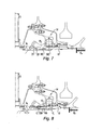
- the engine represented on the figure 1 comprises from upstream to downstream with respect to the gas flow, the following mechanical elements: a fan before 2, a low pressure compressor 3 a high pressure compressor 4, a combustion chamber 5, a high pressure turbine stage 6 receiving the gases from the combustion chamber, a low pressure turbine module 7.
- the fan 2, the low pressure compressor 3 and the low pressure turbine form a rotor integral with a shaft 8 disposed on the axis of the motor.
- the compressor 4 and the high pressure turbine 6 form a second rotor 9 independent of the first and mounted concentrically to the shaft 8 of the first rotor.
- the engine is contained in a casing assembly of which upstream the intermediate casing 11 arranged downstream of the fan casing 12.
- the intermediate casing 11 supports the front bearings of the two rotors, including in particular the support bearing of the trunnion 10. upstream end of the rotor 9 of the high-pressure body.
- the operation of the engine 1 is as follows.
- the air sucked by the fan 2 is divided into two concentric flows: a primary flow and a secondary flow.
- the secondary stream is ejected into the atmosphere and provides most of the thrust.
- the primary flow is guided through the compressors 3 and 4 and then into the combustion chamber 5 where it is mixed with a fuel.
- the high energy gases from the combustion chamber are successively relaxed in the turbines 6 and 7 and set them in motion.
- the turbines in turn drive their associated compressor.
- the gases from the primary flow are ejected downstream and participate in the thrust produced by the engine.
- the figure 2 shows in more detail the interior of the hub of the intermediate housing.
- the intermediate housing 11 supports bearing bearing 14. This bearing is commonly designated bearing three because it is the third from the upstream of the engine. Bearings one and two supporting the fan shafts and low pressure compressor.
- the ball bearing 14 is enclosed in a chamber formed by an upstream sealing flange 15 and a downstream sealing flange 16.
- the bearing 14 supports a sleeve 18 which is integral with a conical wheel 19.
- the conical wheel comprises teeth disposed on a conical surface and cooperating with the teeth of a conical gear 20 disposed substantially perpendicular to the axis XX of the engine.
- the pinion is integral with a radial shaft 21 of which only a part is visible. This shaft extends to the fan housing where it is connected to an AGB gearbox for driving the auxiliary equipment of the engine.
- the end journal 10 of the high-pressure compressor shaft is retained inside the sleeve 18 by a cylindrical nut 23.
- the nut of generally cylindrical shape is screwed inside the pin 10. It abuts in a first axial direction downstream by an outer radial flange 23A against a transverse surface 18A of the sleeve 18. In this case a Scoop 24 centrifugal oil is interposed between the two surfaces 23A and 10B.
- the nut has a thread 23B on its outer surface cooperating with an internal thread 10B of the pin 10.
- a split steel lock ring is housed in an annular groove 23C machined on the outer surface of the nut 23.
- the figure 3 shows the establishment of the ring 25 which is slid along the arrow F in the annular space between the nut 23 and the sleeve 18 before screwing the pin 10. The thickness of the ring is determined so as to allow this passage.
- the figure 4 shows the journal 10 after the nut 23 has been screwed.
- the journal comprises a cylindrical end portion 10A which covers the ring 25. This arrangement ensures the locking of the ring during operation of the engine by maintaining it in the groove 23C.
- the faces of the inner radial flange 18A and the ring 25 which are capable of coming into contact, 18A1 and 25A respectively, are frustoconical.
- the ring 25 includes an axial extension flange 25B which has a foolproof function for the case where it would be mounted upside down. Indeed the extension 25B abuts against the rounded surface portion above the portion 18A1 which would prevent the introduction of the ring into the groove 23C.
- the flange also facilitates the gripping of the split stop ring by a tool during disassembly.
- the nut 23 has been placed in the sleeve 18, abutting against the radial flange 18A of the sleeve.
- the ring 25 was inserted along the gap between the nut and the sleeve and slid into the groove 23C.
- the first step is to heat the sleeve and conical wheel in the bearing to reduce subsequent shrinking efforts.
- a protection thermal I covers the nut so that its thread 23B is not heated.
- the next step, figure 6 consists in axially clamping the nut, both upstream B1 and downstream B2, on a fixed part of the tool, so that the axial mounting forces do not pass through the bearing bearing 3. This could lead to punching bearing tracks by the balls, thereby degrading the life of this bearing.
- the brake comprises a cylindrical portion with tenons 27E which cooperate with notches 23 E at the end of the nut 23 and grooves 27C which cooperate with intents grooves 10I of the journal.
- the brake comprises tabs 27L, at the downstream end of the flexible tabs 27, which are introduced into an internal groove 10F of the pin 10. This brake thus prevents any rotation of the nut in the unscrewing direction.
- Disassembly includes the following operations.
- the brake 27 is removed and the journal is axially locked. figure 10 .
- the groove 10F released by the nut brake is used.
- the nut 23 is unscrewed, it moves upstream until the stop ring 25 comes into contact with the downstream face of the internal radial flange 18A of the conical wheel, figure 11 .
Landscapes
- Engineering & Computer Science (AREA)
- General Engineering & Computer Science (AREA)
- Mechanical Engineering (AREA)
- Structures Of Non-Positive Displacement Pumps (AREA)
- Mounting Of Bearings Or Others (AREA)
- Turbine Rotor Nozzle Sealing (AREA)
Claims (12)
- Gasturbinenantrieb, umfassend eine Welle, ein Lager (14), eine Muffe (18), die vom Lager getragen wird, wobei die Welle von einem Endzapfen (10) im Inneren der Muffe festgespannt wird und an der Muffe (18) mittels einer Ringmutter (23) befestigt ist, dadurch gekennzeichnet, dass die Mutter (23) im Inneren des Zapfens untergebracht ist und axial in eine erste Richtung gegen die Muffe (18) anschlägt, wenn der Zapfen (10) auf die Mutter (23) aufgeschraubt ist, und wobei ein Sicherungsring (25), der in einer ringförmigen Nut (23C) untergebracht ist, die auf der Außenfläche der Mutter (23) ausgebildet ist, den axialen Anschlag gegen die Muffe (18) in die der ersten Richtung entgegengesetzten Richtung bildet, wodurch der Ausbau des Zapfens (10) der Muffe (18) durch Abschrauben der Mutter (23) ermöglicht wird.
- Antrieb nach Anspruch 1, von dem die Dicke des Sicherungsrings (25) geringer ist als der radiale Platz, der zwischen der Mutter (23) und der Muffe (18) ausgebildet ist.
- Antrieb nach Anspruch 1 oder 2, von dem die Fläche (25A) des Sicherungsrings (25) auf Seite der axialen Anschlagsfläche (18A1) der Muffe (18) und die axiale Anschlagsfläche (18A1) der Muffe (18) kegelstumpfförmig sind, sodass die Öffnung des Sicherheitsrings (25) verhindert wird, wenn der Ring gegen die axiale Anschlagsfläche der Muffe anschlägt.
- Antrieb nach dem vorhergehenden Anspruch, von dem der Sicherungsring (25) auf der der Vorhergehenden gegenüberliegenden Seite einen Kragen (25B) als zylindrische Verlängerung umfasst, der eine mechanische Codierung bildet und den Ausbau des Rings erleichtert.
- Antrieb nach einem der vorhergehenden Ansprüche, von dem der Zapfen (10) einen zylindrischen Endabschnitt (10A) aufweist, der den Sicherungsring (25) abdeckt, um den Sicherungsring in der Nut (23C) zu halten.
- Antrieb nach einem der vorhergehenden Ansprüche, von dem die Muffe (18) Teil eines Kegelrads (19) zur mechanischen Leistungsaufnahme für den Antrieb der Zusatzeinrichtungen des Antriebs ist.
- Antrieb nach Anspruch 6, von dem der Zapfen am Ende des Hochdruckkompressors in einem Zwei-Wellen-Antrieb angeordnet ist.
- Antrieb nach dem vorhergehenden Anspruch, von dem der Zapfen (10) des Kompressors im Inneren der Muffe (18) des Kegelrads aufgeschrumpft wird.
- Verfahren zum Einbau des vorgelagerten Endzapfens (10) des Hochdruckkompressors in das Lager (14) des Antriebs nach Anspruch 8, umfassend folgende Schritte: Anbringen der Mutter (23) in der Muffe (18) des Kegelrads, Einsetzen des Sicherungsrings (25) in der Nut (23C) der Mutter, axiales Spannen der Mutter (23), Einfügen des Zapfens (10) des Kompressors, Festschrauben der Mutter (23) im Inneren des Zapfens (10) bei gleichzeitiger axialer Druckausübung nach vorne (Pam) auf den Zapfen, bis zum Anschlag.
- Verfahren nach dem vorhergehenden Anspruch, umfassend den Schritt des Erhitzens der Muffe des Kegelrads vor dem Einfügen des Endzapfens der Kompressorwelle.
- Verfahren nach einem der Ansprüche 9 und 10, umfassend den Einbau einer Mutternsicherung (27).
- Verfahren zum Ausbau des Zapfens (10) des Kompressors aus dem Lager (14) des Antriebs nach Anspruch 8, nach dem Einbau nach Anspruch 9, umfassend folgende Schritte: axiales Blockieren (BA) des Endzapfens (10) des Kompressors, Abschrauben der Mutter (23) bis der Sicherungsring (25) gegen das Kegelrad anschlägt, axiales Spannen (B1, B2) der Mutter, Abschrauben der Mutter bis zum vollständigen Loslösen des Endzapfens des Kompressors bei gleichzeitiger axialer Druckausübung nach hinten (Parr) auf den Zapfen.
Applications Claiming Priority (1)
| Application Number | Priority Date | Filing Date | Title |
|---|---|---|---|
| FR0704544A FR2917783B1 (fr) | 2007-06-25 | 2007-06-25 | Systeme de liaison d'arbre moteur avec ecrou auto-extracteur |
Publications (2)
| Publication Number | Publication Date |
|---|---|
| EP2009252A1 EP2009252A1 (de) | 2008-12-31 |
| EP2009252B1 true EP2009252B1 (de) | 2011-08-31 |
Family
ID=39264541
Family Applications (1)
| Application Number | Title | Priority Date | Filing Date |
|---|---|---|---|
| EP08158908A Active EP2009252B1 (de) | 2007-06-25 | 2008-06-24 | Montage einer Welle in einem Wellenlager mit selbstabziehender Mutter |
Country Status (6)
| Country | Link |
|---|---|
| US (1) | US8152438B2 (de) |
| EP (1) | EP2009252B1 (de) |
| JP (1) | JP5376845B2 (de) |
| CA (1) | CA2634986C (de) |
| FR (1) | FR2917783B1 (de) |
| RU (1) | RU2468213C2 (de) |
Families Citing this family (14)
| Publication number | Priority date | Publication date | Assignee | Title |
|---|---|---|---|---|
| FR2931874B1 (fr) * | 2008-05-29 | 2010-06-25 | Snecma | Dispositif de blocage axial d'un palier de guidage d'arbre dans une turbomachine. |
| FR2942273B1 (fr) * | 2009-02-18 | 2011-06-10 | Snecma | Moteur double flux a roues de turbine contrarotatives |
| FR2963062B1 (fr) | 2010-07-20 | 2012-08-31 | Snecma | Assemblage entre un tourillon d'arbre de compresseur et un pignon conique pour l'entrainement d'un boitier d'accessoires d'une turbomachine |
| EP2415966A1 (de) * | 2010-08-05 | 2012-02-08 | Siemens Aktiengesellschaft | Antriebsstrang für eine Gasturbine |
| FR2975149B1 (fr) * | 2011-05-09 | 2013-06-07 | Snecma | Systeme pour fixer deux pieces tubulaires l'une dans l'autre portant un palier a roulement |
| US8460118B2 (en) | 2011-08-31 | 2013-06-11 | United Technologies Corporation | Shaft assembly for a gas turbine engine |
| FR3007069B1 (fr) * | 2013-06-12 | 2015-07-17 | Snecma | Tourillon pour turbine haute pression, et turboreacteur incluant un tel tourillon |
| US10247029B2 (en) * | 2016-02-04 | 2019-04-02 | United Technologies Corporation | Method for clearance control in a gas turbine engine |
| US10280842B2 (en) | 2017-04-10 | 2019-05-07 | United Technologies Corporation | Nut with air seal |
| FR3066534B1 (fr) * | 2017-05-22 | 2020-01-10 | Safran Aircraft Engines | Ensemble pour turbomachine d'aeronef presentant un systeme de decouplage ameliore en cas de perte d'aube de soufflante |
| FR3093537B1 (fr) * | 2019-03-08 | 2021-06-11 | Safran Aircraft Engines | Sous ensemble de montage d'un palier de guidage d'un arbre de compresseur |
| FR3108935B1 (fr) * | 2020-04-02 | 2022-03-04 | Safran Aircraft Engines | Dispositif de distribution d’huile d’un palier a roulement de turbomachine d’aeronef |
| US11215077B1 (en) * | 2020-08-17 | 2022-01-04 | Raytheon Technologies Corporation | Integral gear support and bearing damper pedestal |
| BE1028685B1 (fr) | 2020-10-08 | 2022-05-12 | Safran Aero Boosters | Système pour désolidariser un arbre moteur d'un support de palier |
Family Cites Families (15)
| Publication number | Priority date | Publication date | Assignee | Title |
|---|---|---|---|---|
| SU8267A1 (ru) * | 1925-06-15 | 1929-03-30 | Ройс Ф.Р.Г. | Тормозное устройство дл самодвижущихс экипажей |
| GB802263A (en) * | 1954-11-22 | 1958-10-01 | Rolls Royce | Improvements in or relating to locking means for parts interengaged by screw threads |
| GB2080486B (en) * | 1980-07-15 | 1984-02-15 | Rolls Royce | Shafts |
| FR2783579B1 (fr) * | 1998-09-17 | 2000-11-03 | Snecma | Agencement de retenue d'un palier, notamment pour un arbre de compresseur a haute pression |
| FR2824362B1 (fr) * | 2001-05-03 | 2003-09-05 | Snecma Moteurs | Agencement de montage de deux lignes d'arbre coaxiales |
| US6540483B2 (en) * | 2001-08-27 | 2003-04-01 | General Electric Company | Methods and apparatus for bearing outer race axial retention |
| US6783319B2 (en) * | 2001-09-07 | 2004-08-31 | General Electric Co. | Method and apparatus for supporting rotor assemblies during unbalances |
| GB2383380B (en) * | 2001-12-19 | 2005-05-25 | Rolls Royce Plc | Rotor assemblies for gas turbine engines |
| FR2857708B1 (fr) * | 2003-07-15 | 2005-09-23 | Snecma Moteurs | Dispositif perfectionne de fixation d'un arbre de moteur sur un support de palier |
| FR2858649B1 (fr) * | 2003-08-05 | 2005-09-23 | Snecma Moteurs | Turbine basse-pression de turbomachine |
| US7097413B2 (en) * | 2004-05-12 | 2006-08-29 | United Technologies Corporation | Bearing support |
| FR2873161B1 (fr) * | 2004-07-15 | 2008-10-10 | Snecma Moteurs Sa | Ensemble comprenant un arbre rotatif et un palier a roulement |
| FR2882096B1 (fr) * | 2005-02-11 | 2012-04-20 | Snecma Moteurs | Turbomoteur a double corps avec des moyens de prise de mouvement sur les rotors basse pression et haute pression, module de prise de mouvement pour le turbomoteur et procede de montage du turbomoteur |
| US7493753B2 (en) * | 2005-10-19 | 2009-02-24 | General Electric Company | Gas turbine engine assembly and methods of assembling same |
| US7883311B2 (en) * | 2006-12-20 | 2011-02-08 | General Electric Company | Bearing assembly and method of assembling the same |
-
2007
- 2007-06-25 FR FR0704544A patent/FR2917783B1/fr not_active Expired - Fee Related
-
2008
- 2008-06-20 CA CA2634986A patent/CA2634986C/fr active Active
- 2008-06-24 RU RU2008125812/06A patent/RU2468213C2/ru active
- 2008-06-24 US US12/145,006 patent/US8152438B2/en active Active
- 2008-06-24 EP EP08158908A patent/EP2009252B1/de active Active
- 2008-06-24 JP JP2008164107A patent/JP5376845B2/ja active Active
Also Published As
| Publication number | Publication date |
|---|---|
| EP2009252A1 (de) | 2008-12-31 |
| FR2917783A1 (fr) | 2008-12-26 |
| CA2634986A1 (fr) | 2008-12-25 |
| US20080317594A1 (en) | 2008-12-25 |
| CA2634986C (fr) | 2015-02-03 |
| JP5376845B2 (ja) | 2013-12-25 |
| JP2009002348A (ja) | 2009-01-08 |
| FR2917783B1 (fr) | 2013-04-12 |
| RU2468213C2 (ru) | 2012-11-27 |
| US8152438B2 (en) | 2012-04-10 |
| RU2008125812A (ru) | 2009-12-27 |
Similar Documents
| Publication | Publication Date | Title |
|---|---|---|
| EP2009252B1 (de) | Montage einer Welle in einem Wellenlager mit selbstabziehender Mutter | |
| EP3071792B1 (de) | Modulares triebwerk | |
| EP2281109B1 (de) | Turbomotor mit einer reversiblen elektrischen maschine | |
| CA2929798C (fr) | Enceinte avant etanche lors du desassemblage modulaire d'un turboreacteur a reducteur | |
| EP3137741B1 (de) | Flugzeugtriebwerk mit verbessertem der ziehen mechanischen leistung | |
| EP3137740B1 (de) | Anordnung für flugzeugtriebwerk und verfahren zur deren montage | |
| FR2963062A1 (fr) | Assemblage entre un tourillon d'arbre de compresseur et un pignon conique pour l'entrainement d'un boitier d'accessoires d'une turbomachine | |
| EP4240951B1 (de) | Modularität einer flugzeugturbomaschine | |
| EP3584413B1 (de) | Ringförmiges und aufgeschrumpftes gussteil für ein turbotriebwerk eines luftfahrzeugs | |
| WO2013190246A1 (fr) | Moteur a turbine a gaz comportant un cône d'échappement fixe au carter d'échappement | |
| EP2469100A1 (de) | Motorkompressor mit Drehkupplung in einer Hohlwelle des Kompressors | |
| EP3124795B1 (de) | Gebläse mit scheibe für einen turboreaktor sowie turboreaktor | |
| WO2011148078A2 (fr) | Boite d'engrenages dans une turbomachine | |
| EP4248074B1 (de) | Antriebswelle eines flugzeugturbinentriebwerks mit einem verbindungsring zum ausbau der antriebswelle | |
| FR3140124A1 (fr) | Turbomachine comprenant plusieurs modules et un dispositif de blocage de ces modules, et procede de demontage correspondant | |
| EP4240950B1 (de) | Modularität einer flugzeugturbomaschine | |
| WO2022144514A1 (fr) | Module de turbomachine equipe d'une machine electrique et turbomachine equipee d'un tel module | |
| EP4273391B1 (de) | Vormontageverfahren für eine flugzeugturbomaschine | |
| EP4411178B1 (de) | Strömungsmaschine mit einem drehzahlminderer mit durch eine zahnkupplung gekoppelten befestigungsflanschen | |
| WO2025133528A1 (fr) | Turbomachine comprenant plusieurs modules et un dispositif de blocage de ces modules, et procede de montage correspondant | |
| FR3162797A1 (fr) | Turbomachine comprenant plusieurs modules et un dispositif de blocage de ces modules, et procede de montage correspondant | |
| FR3164504A1 (fr) | Systeme d’accouplement ameliore de deux pieces de turbomachine d’aeronef, de preference deux arbres de turbomachine | |
| FR3140123A1 (fr) | Modularite d’une turbomachine d’aeronef par un dispositif de blocage axial et en rotation, procede de montage correspondant | |
| FR3135756A1 (fr) | boitier de relais d’accessoires perfectionné |
Legal Events
| Date | Code | Title | Description |
|---|---|---|---|
| PUAI | Public reference made under article 153(3) epc to a published international application that has entered the european phase |
Free format text: ORIGINAL CODE: 0009012 |
|
| 17P | Request for examination filed |
Effective date: 20080624 |
|
| AK | Designated contracting states |
Kind code of ref document: A1 Designated state(s): AT BE BG CH CY CZ DE DK EE ES FI FR GB GR HR HU IE IS IT LI LT LU LV MC MT NL NO PL PT RO SE SI SK TR |
|
| AX | Request for extension of the european patent |
Extension state: AL BA MK RS |
|
| AKX | Designation fees paid |
Designated state(s): DE FR GB |
|
| GRAP | Despatch of communication of intention to grant a patent |
Free format text: ORIGINAL CODE: EPIDOSNIGR1 |
|
| GRAS | Grant fee paid |
Free format text: ORIGINAL CODE: EPIDOSNIGR3 |
|
| GRAA | (expected) grant |
Free format text: ORIGINAL CODE: 0009210 |
|
| AK | Designated contracting states |
Kind code of ref document: B1 Designated state(s): DE FR GB |
|
| REG | Reference to a national code |
Ref country code: GB Ref legal event code: FG4D Free format text: NOT ENGLISH |
|
| REG | Reference to a national code |
Ref country code: DE Ref legal event code: R096 Ref document number: 602008009243 Country of ref document: DE Effective date: 20111110 |
|
| PLBE | No opposition filed within time limit |
Free format text: ORIGINAL CODE: 0009261 |
|
| STAA | Information on the status of an ep patent application or granted ep patent |
Free format text: STATUS: NO OPPOSITION FILED WITHIN TIME LIMIT |
|
| 26N | No opposition filed |
Effective date: 20120601 |
|
| REG | Reference to a national code |
Ref country code: DE Ref legal event code: R097 Ref document number: 602008009243 Country of ref document: DE Effective date: 20120601 |
|
| REG | Reference to a national code |
Ref country code: FR Ref legal event code: PLFP Year of fee payment: 8 |
|
| REG | Reference to a national code |
Ref country code: FR Ref legal event code: PLFP Year of fee payment: 9 |
|
| REG | Reference to a national code |
Ref country code: FR Ref legal event code: PLFP Year of fee payment: 10 |
|
| REG | Reference to a national code |
Ref country code: FR Ref legal event code: CD Owner name: SAFRAN AIRCRAFT ENGINES, FR Effective date: 20170719 |
|
| REG | Reference to a national code |
Ref country code: FR Ref legal event code: PLFP Year of fee payment: 11 |
|
| PGFP | Annual fee paid to national office [announced via postgrant information from national office to epo] |
Ref country code: DE Payment date: 20250618 Year of fee payment: 18 |
|
| PGFP | Annual fee paid to national office [announced via postgrant information from national office to epo] |
Ref country code: GB Payment date: 20250625 Year of fee payment: 18 |
|
| PGFP | Annual fee paid to national office [announced via postgrant information from national office to epo] |
Ref country code: FR Payment date: 20250623 Year of fee payment: 18 |