EP2009248A1 - Turbinenanordnung und Verfahren zur Kühlung eines Deckbands an der Spitze einer Turbinenschaufel - Google Patents
Turbinenanordnung und Verfahren zur Kühlung eines Deckbands an der Spitze einer Turbinenschaufel Download PDFInfo
- Publication number
- EP2009248A1 EP2009248A1 EP07012388A EP07012388A EP2009248A1 EP 2009248 A1 EP2009248 A1 EP 2009248A1 EP 07012388 A EP07012388 A EP 07012388A EP 07012388 A EP07012388 A EP 07012388A EP 2009248 A1 EP2009248 A1 EP 2009248A1
- Authority
- EP
- European Patent Office
- Prior art keywords
- rotor
- shroud
- supersonic
- cooling fluid
- turbine
- Prior art date
- Legal status (The legal status is an assumption and is not a legal conclusion. Google has not performed a legal analysis and makes no representation as to the accuracy of the status listed.)
- Granted
Links
Images

Classifications
-
- F—MECHANICAL ENGINEERING; LIGHTING; HEATING; WEAPONS; BLASTING
- F01—MACHINES OR ENGINES IN GENERAL; ENGINE PLANTS IN GENERAL; STEAM ENGINES
- F01D—NON-POSITIVE DISPLACEMENT MACHINES OR ENGINES, e.g. STEAM TURBINES
- F01D5/00—Blades; Blade-carrying members; Heating, heat-insulating, cooling or antivibration means on the blades or the members
- F01D5/12—Blades
- F01D5/22—Blade-to-blade connections, e.g. for damping vibrations
- F01D5/225—Blade-to-blade connections, e.g. for damping vibrations by shrouding
-
- F—MECHANICAL ENGINEERING; LIGHTING; HEATING; WEAPONS; BLASTING
- F01—MACHINES OR ENGINES IN GENERAL; ENGINE PLANTS IN GENERAL; STEAM ENGINES
- F01D—NON-POSITIVE DISPLACEMENT MACHINES OR ENGINES, e.g. STEAM TURBINES
- F01D11/00—Preventing or minimising internal leakage of working-fluid, e.g. between stages
- F01D11/08—Preventing or minimising internal leakage of working-fluid, e.g. between stages for sealing space between rotor blade tips and stator
- F01D11/10—Preventing or minimising internal leakage of working-fluid, e.g. between stages for sealing space between rotor blade tips and stator using sealing fluid, e.g. steam
-
- F—MECHANICAL ENGINEERING; LIGHTING; HEATING; WEAPONS; BLASTING
- F01—MACHINES OR ENGINES IN GENERAL; ENGINE PLANTS IN GENERAL; STEAM ENGINES
- F01D—NON-POSITIVE DISPLACEMENT MACHINES OR ENGINES, e.g. STEAM TURBINES
- F01D25/00—Component parts, details, or accessories, not provided for in, or of interest apart from, other groups
- F01D25/08—Cooling; Heating; Heat-insulation
- F01D25/12—Cooling
-
- F—MECHANICAL ENGINEERING; LIGHTING; HEATING; WEAPONS; BLASTING
- F05—INDEXING SCHEMES RELATING TO ENGINES OR PUMPS IN VARIOUS SUBCLASSES OF CLASSES F01-F04
- F05D—INDEXING SCHEME FOR ASPECTS RELATING TO NON-POSITIVE-DISPLACEMENT MACHINES OR ENGINES, GAS-TURBINES OR JET-PROPULSION PLANTS
- F05D2240/00—Components
- F05D2240/10—Stators
- F05D2240/11—Shroud seal segments
-
- F—MECHANICAL ENGINEERING; LIGHTING; HEATING; WEAPONS; BLASTING
- F05—INDEXING SCHEMES RELATING TO ENGINES OR PUMPS IN VARIOUS SUBCLASSES OF CLASSES F01-F04
- F05D—INDEXING SCHEME FOR ASPECTS RELATING TO NON-POSITIVE-DISPLACEMENT MACHINES OR ENGINES, GAS-TURBINES OR JET-PROPULSION PLANTS
- F05D2250/00—Geometry
- F05D2250/30—Arrangement of components
- F05D2250/32—Arrangement of components according to their shape
- F05D2250/323—Arrangement of components according to their shape convergent
-
- F—MECHANICAL ENGINEERING; LIGHTING; HEATING; WEAPONS; BLASTING
- F05—INDEXING SCHEMES RELATING TO ENGINES OR PUMPS IN VARIOUS SUBCLASSES OF CLASSES F01-F04
- F05D—INDEXING SCHEME FOR ASPECTS RELATING TO NON-POSITIVE-DISPLACEMENT MACHINES OR ENGINES, GAS-TURBINES OR JET-PROPULSION PLANTS
- F05D2250/00—Geometry
- F05D2250/30—Arrangement of components
- F05D2250/32—Arrangement of components according to their shape
- F05D2250/324—Arrangement of components according to their shape divergent
Definitions
- the present invention relates to a turbine arrangement with a rotor and a stator surrounding the rotor so as to form a flow path for hot and pressurised combustion gases between the rotor and the stator, the rotor comprising turbine blades extending in a substantially radial direction through the flow path towards the stator and having a shroud located at their tips.
- the invention relates to a method of cooling a shroud located at the tip of a turbine blade of a rotor while the rotor is turning.
- Shrouds at the radial outer end of gas turbine blades are used for sealing the gap between the tip of the turbine blade and the turbine stator surrounding the turbine blade. By this measure a leakage flow through the gap between the tip and the stator is reduced.
- a typical shroud extends in the circumferential direction of the rotor and in the axial direction of the rotor along a substantial length of the turbine blade, in particular along its whole axial length, i.e. over a large area of the inner wall of the stator.
- EP 1 083 299 A2 describes a gas turbine with a stator and a rotor from which turbine blades extend towards the stator. At the radial outer tip of a turbine blade a shroud is located which faces a honeycomb seal structure at the inner wall of the stator. Cooling air is blown out of an opening in the stator wall into the gap between the shroud and the stator wall directly upstream from the honeycomb seal structure.
- the first objective is solved by a turbine arrangement according to claim 1.
- the second objective is solved by a method of cooling a shroud as claimed in claim 8.
- the depending claims contain further developments of the invention.
- An inventive turbine arrangement comprises a rotor and a stator surrounding the rotor so as to form a flow path for hot and pressurised combustion gases between the rotor and the stator.
- the rotor defines a radial direction and a circumferential direction and comprises turbine blades extending in the radial direction through the flow path towards the stator and having a shroud located at their tip.
- the stator comprises a wall section along which the shroud moves when the rotor is turning.
- At least one supersonic nozzle is located in the wall section and connected to a cooling fluid provider. The supersonic nozzle is located such as to provide a supersonic cooling fluid flow towards the shroud.
- a supersonic nozzle may be simply realised by a converging-diverging nozzle cross section.
- the flow towards the shroud will have a very high velocity.
- This flow will mix with an overlap leakage through the radial gap between the shroud and the inner wall of the stator.
- This leakage has a lower velocity in the circumferential direction than the supersonic flow emerging from the supersonic nozzle.
- the supersonic flow will increase the circumferential velocity of the mix which will lead to a lower relative velocity in the shroud's rotating frame of reference, whereby the cooling efficiency of the shroud cooling is increased.
- the relative circumferential velocity of the shroud and the gas in the gap between the shroud and the stator is high in the state of the art cooling arrangements.
- the friction between the gas and the shroud is high and, as a consequence, the temperature of the gas is increased. This increase lowers the capability of heat dissipation from the shroud.
- the cooling fluid provider may be the gas turbine's compressor which also supplies the combustion system with combustion air. The cooling fluid is then just compressed air from the compressor. An additional cooling fluid provider is thus not necessary.
- a seal is advantageously located in the wall section along which the shroud moves.
- This seal is partly or fully plain and the supersonic nozzle is located in the plain seal or its plain section if it is only partly plain.
- Such a plain seal (section) reduces friction between the supersonic flow and the stator wall as compared to non-plain seals.
- the seal in the stator's wall may, in particular, comprise a plain section and a honeycomb section where the honeycomb section is located upstream from the plain section.
- an impingement jet may be directed onto the shroud.
- an impingement jet opening would be present upstream from the seal in the stator. This opening would be located and oriented such as to provide an impingement jet directed towards the shroud.
- the supersonic flow emerging from the supersonic nozzle can also impinge on the shroud so as to provide some degree of impingement cooling.
- the impingement jet opening could also be implemented such as to provide a supersonic cooling fluid flow with or without an inclination towards the circumferential direction of the rotor.
- a supersonic cooling fluid flow which has a component in its flow direction that is parallel to the moving direction of the shroud of the turning rotor blade.
- Such supersonic cooling fluid flow would mix with a leakage flow flowing in the substantially axial direction of the rotor through the gap between the shroud and the inner wall of the stator.
- the mixture of the supersonic cooling fluid flow and the leakage flow would, as a consequence, have a circumferential velocity component that decreases the relative velocity between the shroud and the gas flow through the gap.
- the velocity reduction in the turbine frame of reference leads to a reduced warming of the gas in the gap by the movement of the rotating rotor and hence to an improved cooling efficiency as warming the gas by the movement would mean a reduced capability of dissipating heat from the shroud itself.
- the supersonic cooling fluid flow may have a radial component which allows it to impinge on the shroud so as to provide some degree of impingement cooling.
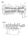
- Figure 1 shows, in a highly schematic view, a gas turbine engine 1 comprising a compressor section 3, a combustor section 5 and a turbine section 7.
- a rotor 9 extends through all sections and comprises, in the compressor section 3, rows of compressor blades 11 and, in the turbine section 7, rows of turbine blades 13 which may be equipped with shrouds at their tips. Between neighbouring rows of compressor blades 11 and between neighbouring rows of turbine blades 13 rows of compressor vanes 15 and turbine vanes 17, respectively, extend from a stator or housing 19 of the gas turbine engine 1 radially inwards towards the rotor 9.
- air is taken in through an air inlet 21 of the compressor section 3.
- the air is compressed and led towards the combustor section 5 by the rotating compressor blades 11.
- the air is mixed with a gaseous or liquid fuel and the mixture is burnt.
- the hot and pressurised combustion gas resulting from burning the fuel/air mixture is fed to the turbine section 7.
- the hot pressurised gas transfers momentum to the turbine blades 13 while expanding and cooling, thereby imparting a rotational movement to the rotor 9 that drives the compressor and a consumer, e.g. a generator for producing electrical power or an industrial machine.
- the expanded and cooled combustion gas leaves the turbine section 7 through an exhaust 23.
- FIG. 2 shows a section through the arrangement along the rotor's axial direction
- Figure 3 shows a section of the arrangement along the rotor's radial direction.
- the figures show a turbine blade 13 with a shroud 25 located at its tip, i.e. its radial outer end. It further shows a wall section 27 of the stator 19 (or housing) of the turbine.
- a plain seal 29 is located on the inner surface of the inner wall 27 where the shroud 25 faces the wall.
- the shroud 25 is equipped with fins 31 extending radially outwards from a shroud platform 33 towards the seal 29.
- These fins 31 provide a labyrinth seal function that reduces the pressure of a gas flowing through the gap between the shroud 25 and the wall 27.
- a cooling channel 30 is provided in an upstream section 32 of the wall 27 by which an impingement jet can be blown towards an upstream part of the shroud 25.
- the main flow direction of the hot and pressurised combustion gases is indicated by the arrow 35 in Figure 2 .
- a minor part of the flow leaks through the gap between the shroud 25 and the wall 27 of the stator 19.
- This leakage flow is indicated by arrow 37.
- This leakage flow 37 is mainly directed parallel to the axial direction of the rotor 9. The pressure of the leakage flow will be reduced by the labyrinth seal.
- a converging-diverging nozzle 39 is provided in the stator wall 27.
- This nozzle forms the supersonic nozzle which connects the gap between the shroud 25 and the wall 27 with a plenum 41 at the other side of the wall 27.
- the plenum 41 is in flow connection with the compressor exit and hence contains compressed air from the compressor. The compressed air from the compressor is let through the plenum 41 to the supersonic nozzle 39 and blown out by the nozzle towards the shroud 25.
- Increased velocities of the cooling fluid are achieved by the use of the converging-diverging configuration of the nozzle where supersonic flows are generated at the nozzle's exit opening 45.
- the nozzle 39 is arranged such in the wall section 27 and the plain seal 29 that its exit opening 45 faces a downstream cavity 43 which is defined by the space between the two most downstream fins 31. Therefore, the supersonic cooling fluid flow emerges from the nozzle 39 into this downstream cavity 43 where the gas pressure has already been reduced by the action of the fin 31 being located upstream of the cavity. Therefore a high pressure ratio is obtained by using high pressure compressor delivery air for the cooling fluid supply to the nozzle 39.
- the nozzle 39 is inclined with respect to the radial direction of the rotor 9, as can be seen in Figure 3 .
- the inclination is such that the supersonic cooling fluid flow enters the gap between the shroud 25 and the wall 27 with a velocity component which is parallel to the moving direction 48 of the shrouds 25 when the rotor is rotating.
- the flow direction at the nozzle's exit opening 45 is indicated by arrow 46.
- the supersonic cooling air flow is pre-swirled in the same direction as the rotor blade 13 with the shroud 25 rotates.
- the flow will be supersonic and have a very high velocity.
- This supersonic cooling air flow will mix with the leakage flow entering the gap between the shroud 25 and the wall 27 along the flow path which is indicated by arrow 37.
- This leakage flow will have a lower velocity in the circumferential direction and thus be a source of friction between the leakage flow 37 and the shroud 25.
- the supersonic cooling fluid flow 46 with a circumferential velocity direction the velocity of the mix of supersonic cooling air and leakage flow will be increased in the circumferential direction of the rotor 9.
- Figure 4 shows a section through the shroud 25 and the wall 27 of the stator which is taken along the axial direction of the rotor 9.
- Elements which are identical to elements of the first embodiment are designated with the same reference numerals as in Figure 2 and will not be described again in order to avoid repetition.
- the seal in the first embodiment is a simple plain seal 29
- the seal in the second embodiment is a combination of a plain seal section 129 and a honeycomb seal section 131.
- the plain seal section 129 is located in a downstream section of the wall facing the shroud 25
- the honeycomb seal section 131 is located in an upstream section of the wall facing the shroud 25.
- This second embodiment is particularly suitable for use in conjunction with turbines of large size.
- a plain seal section should surround the converging-diverging nozzle 39 to give reduced friction as compared to a honeycomb seal and therefore not to reduce the velocity of the fluid in the gap in the circumferential direction of the rotor 9. Otherwise, the second embodiment does not differ from the first embodiment.
- supersonic nozzle 39 Although only one supersonic nozzle 39 has been described, supersonic nozzles will usually be distributed over the whole circumference of those stator wall sections facing shrouds of turbine blades.
Priority Applications (8)
| Application Number | Priority Date | Filing Date | Title |
|---|---|---|---|
| ES07012388T ES2341897T3 (es) | 2007-06-25 | 2007-06-25 | Disposicion de turbina y procedimiento de enfriamiento de un aro de refuerzo ubicado en la planta de un alabe de turbina. |
| DE602007006468T DE602007006468D1 (de) | 2007-06-25 | 2007-06-25 | Turbinenanordnung und Verfahren zur Kühlung eines Deckbands an der Spitze einer Turbinenschaufel |
| EP07012388A EP2009248B1 (de) | 2007-06-25 | 2007-06-25 | Turbinenanordnung und Verfahren zur Kühlung eines Deckbands an der Spitze einer Turbinenschaufel |
| AT07012388T ATE467750T1 (de) | 2007-06-25 | 2007-06-25 | Turbinenanordnung und verfahren zur kühlung eines deckbands an der spitze einer turbinenschaufel |
| CN2008800217374A CN101688448B (zh) | 2007-06-25 | 2008-06-18 | 涡轮装置和冷却位于涡轮叶片尖端的覆环的方法 |
| PCT/EP2008/057709 WO2009000728A1 (en) | 2007-06-25 | 2008-06-18 | Turbine arrangement and method of cooling a shroud located at the tip of a turbine blade |
| US12/664,742 US8550774B2 (en) | 2007-06-25 | 2008-06-18 | Turbine arrangement and method of cooling a shroud located at the tip of a turbine blade |
| RU2010102036/06A RU2462600C2 (ru) | 2007-06-25 | 2008-06-18 | Устройство турбины и способ охлаждения бандажа, расположенного у кромки лопатки турбины |
Applications Claiming Priority (1)
| Application Number | Priority Date | Filing Date | Title |
|---|---|---|---|
| EP07012388A EP2009248B1 (de) | 2007-06-25 | 2007-06-25 | Turbinenanordnung und Verfahren zur Kühlung eines Deckbands an der Spitze einer Turbinenschaufel |
Publications (2)
| Publication Number | Publication Date |
|---|---|
| EP2009248A1 true EP2009248A1 (de) | 2008-12-31 |
| EP2009248B1 EP2009248B1 (de) | 2010-05-12 |
Family
ID=38753553
Family Applications (1)
| Application Number | Title | Priority Date | Filing Date |
|---|---|---|---|
| EP07012388A Not-in-force EP2009248B1 (de) | 2007-06-25 | 2007-06-25 | Turbinenanordnung und Verfahren zur Kühlung eines Deckbands an der Spitze einer Turbinenschaufel |
Country Status (8)
| Country | Link |
|---|---|
| US (1) | US8550774B2 (de) |
| EP (1) | EP2009248B1 (de) |
| CN (1) | CN101688448B (de) |
| AT (1) | ATE467750T1 (de) |
| DE (1) | DE602007006468D1 (de) |
| ES (1) | ES2341897T3 (de) |
| RU (1) | RU2462600C2 (de) |
| WO (1) | WO2009000728A1 (de) |
Cited By (11)
| Publication number | Priority date | Publication date | Assignee | Title |
|---|---|---|---|---|
| WO2011007366A1 (en) * | 2009-07-17 | 2011-01-20 | Vaigunth Ener Tek (P) Ltd. | An improved turbine and method thereof |
| EP2341217A1 (de) * | 2009-12-30 | 2011-07-06 | Siemens Aktiengesellschaft | Turbine zur Umwandlung von Energie und Verfahren zu ihrem Betrieb |
| WO2011079997A1 (en) * | 2009-12-30 | 2011-07-07 | Siemens Aktiengesellschaft | Turbine for converting energy and method for operating the same |
| EP2390466A1 (de) | 2010-05-27 | 2011-11-30 | Alstom Technology Ltd | Eine Kühlanordnung für eine Gasturbine |
| ITMI20101919A1 (it) * | 2010-10-20 | 2012-04-21 | Ansaldo Energia Spa | Turbina a gas provvista di un circuito per il raffreddamento di sezioni di sommita' di pale rotoriche |
| EP2484872A1 (de) * | 2011-02-07 | 2012-08-08 | General Electric Company | Passives Kühlsystem für eine Turbomaschine |
| WO2014191780A1 (en) * | 2013-05-31 | 2014-12-04 | Cummins Ltd | A seal assembly |
| FR3053385A1 (fr) * | 2016-06-29 | 2018-01-05 | Safran Helicopter Engines | Roue de turbomachine |
| FR3053386A1 (fr) * | 2016-06-29 | 2018-01-05 | Safran Helicopter Engines | Roue de turbine |
| WO2019122540A1 (fr) * | 2017-12-19 | 2019-06-27 | Safran Helicopter Engines | Roue de turbomachine avec léchettes convexe ou concave |
| CN114776403A (zh) * | 2021-12-29 | 2022-07-22 | 东方电气集团东方汽轮机有限公司 | 一种适用于大焓降小流量透平进气结构及其方法 |
Families Citing this family (17)
| Publication number | Priority date | Publication date | Assignee | Title |
|---|---|---|---|---|
| RU2547542C2 (ru) * | 2010-11-29 | 2015-04-10 | Альстом Текнолоджи Лтд | Осевая газовая турбина |
| EP2495399B1 (de) * | 2011-03-03 | 2016-11-23 | Safran Aero Booster S.A. | Segmentierter Stator-Außenring zum Kompensieren von Rotorverschiebungen gegenüber dem Stator |
| US20130318996A1 (en) * | 2012-06-01 | 2013-12-05 | General Electric Company | Cooling assembly for a bucket of a turbine system and method of cooling |
| GB201311333D0 (en) * | 2013-06-26 | 2013-08-14 | Rolls Royce Plc | Component for use in releasing a flow of material into an environment subject to periodic fluctuations in pressure |
| EP2837856B1 (de) * | 2013-08-14 | 2016-10-26 | General Electric Technology GmbH | Flüssigkeitsdichtungsanordnung und Verfahren zum Einziehen einer Leckageströmung durch eine Leckagekluft |
| EP3009613B1 (de) * | 2014-08-19 | 2019-01-30 | United Technologies Corporation | Kontaktlose dichtungen für gasturbinenmotoren |
| DE102015216208A1 (de) * | 2015-08-25 | 2017-03-02 | Rolls-Royce Deutschland Ltd & Co Kg | Dichtelement für eine Turbomaschine, Turbomaschine mit einem Dichtelement und Verfahren zur Herstellung eines Dichtelementes |
| JP6209199B2 (ja) * | 2015-12-09 | 2017-10-04 | 三菱日立パワーシステムズ株式会社 | シールフィン,シール構造,ターボ機械及びシールフィンの製造方法 |
| RU2624691C1 (ru) * | 2016-05-10 | 2017-07-05 | Акционерное общество "Научно-производственный центр газотурбостроения "Салют" (АО "НПЦ газотурбостроения "Салют") | Устройство охлаждения уплотнительных гребней бандажных полок рабочих лопаток турбины |
| US10408077B2 (en) * | 2017-01-26 | 2019-09-10 | United Tehnologies Corporation | Gas turbine seal |
| EP3358142B1 (de) * | 2017-02-02 | 2021-08-18 | General Electric Company | Kontrolle der spaltleckage über ein turbinenschaufeldeckband |
| JP6916755B2 (ja) * | 2018-03-09 | 2021-08-11 | 三菱重工業株式会社 | 回転機械 |
| US10907501B2 (en) * | 2018-08-21 | 2021-02-02 | General Electric Company | Shroud hanger assembly cooling |
| US10815828B2 (en) | 2018-11-30 | 2020-10-27 | General Electric Company | Hot gas path components including plurality of nozzles and venturi |
| US10753208B2 (en) | 2018-11-30 | 2020-08-25 | General Electric Company | Airfoils including plurality of nozzles and venturi |
| CN113266431B (zh) * | 2021-06-03 | 2022-08-09 | 西安交通大学 | 向心透平叶尖间隙超声波密封结构 |
| CN114738119A (zh) * | 2022-04-18 | 2022-07-12 | 中国航发沈阳发动机研究所 | 一种篦齿封严结构 |
Citations (6)
| Publication number | Priority date | Publication date | Assignee | Title |
|---|---|---|---|---|
| EP0365195A2 (de) * | 1988-10-12 | 1990-04-25 | ROLLS-ROYCE plc | Laserbearbeitungsverfahren |
| EP1083299A2 (de) | 1999-09-07 | 2001-03-14 | General Electric Company | Innnengekühlte Deckringsegmente für Turbomaschinenschaufeln |
| EP1219788A2 (de) * | 2000-12-28 | 2002-07-03 | ALSTOM Power N.V. | Anordnung der Leitschaufelplattformen in einer Axialturbine zur Verminderung der Spaltverluste |
| DE10336863A1 (de) * | 2002-09-17 | 2004-03-25 | Alstom (Switzerland) Ltd. | Thermische Turbomaschine |
| GB2409247A (en) | 2003-12-20 | 2005-06-22 | Rolls Royce Plc | A seal arrangement |
| US20070071593A1 (en) * | 2004-04-30 | 2007-03-29 | Ulrich Rathmann | Blade for a gas turbine |
Family Cites Families (10)
| Publication number | Priority date | Publication date | Assignee | Title |
|---|---|---|---|---|
| US3314649A (en) * | 1963-04-15 | 1967-04-18 | Gen Electric | Turbomachine cooling system |
| US3816022A (en) * | 1972-09-01 | 1974-06-11 | Gen Electric | Power augmenter bucket tip construction for open-circuit liquid cooled turbines |
| US3970319A (en) * | 1972-11-17 | 1976-07-20 | General Motors Corporation | Seal structure |
| US4311431A (en) * | 1978-11-08 | 1982-01-19 | Teledyne Industries, Inc. | Turbine engine with shroud cooling means |
| FR2570764B1 (fr) * | 1984-09-27 | 1986-11-28 | Snecma | Dispositif de controle automatique du jeu d'un joint a labyrinthe de turbomachine |
| US4752185A (en) * | 1987-08-03 | 1988-06-21 | General Electric Company | Non-contacting flowpath seal |
| SU1749494A1 (ru) | 1988-07-15 | 1992-07-23 | Московский авиационный институт им.Серго Орджоникидзе | Турбина с устройством дл уплотнени радиального зазора |
| RU31814U1 (ru) | 2003-02-17 | 2003-08-27 | Открытое акционерное общество "Нефтемаш" | Установка для замера дебита продукции нефтяных скважин "Дебит" |
| RU2289029C2 (ru) | 2004-02-05 | 2006-12-10 | Государственное предприятие "Запорожское машиностроительное конструкторское бюро "Прогресс" им. акад. А.Г. Ивченко" | Устройство подвода охлаждающего воздуха к рабочим лопаткам колеса турбины |
| US7334985B2 (en) * | 2005-10-11 | 2008-02-26 | United Technologies Corporation | Shroud with aero-effective cooling |
-
2007
- 2007-06-25 DE DE602007006468T patent/DE602007006468D1/de active Active
- 2007-06-25 ES ES07012388T patent/ES2341897T3/es active Active
- 2007-06-25 AT AT07012388T patent/ATE467750T1/de not_active IP Right Cessation
- 2007-06-25 EP EP07012388A patent/EP2009248B1/de not_active Not-in-force
-
2008
- 2008-06-18 CN CN2008800217374A patent/CN101688448B/zh not_active Expired - Fee Related
- 2008-06-18 WO PCT/EP2008/057709 patent/WO2009000728A1/en active Application Filing
- 2008-06-18 US US12/664,742 patent/US8550774B2/en not_active Expired - Fee Related
- 2008-06-18 RU RU2010102036/06A patent/RU2462600C2/ru not_active IP Right Cessation
Patent Citations (6)
| Publication number | Priority date | Publication date | Assignee | Title |
|---|---|---|---|---|
| EP0365195A2 (de) * | 1988-10-12 | 1990-04-25 | ROLLS-ROYCE plc | Laserbearbeitungsverfahren |
| EP1083299A2 (de) | 1999-09-07 | 2001-03-14 | General Electric Company | Innnengekühlte Deckringsegmente für Turbomaschinenschaufeln |
| EP1219788A2 (de) * | 2000-12-28 | 2002-07-03 | ALSTOM Power N.V. | Anordnung der Leitschaufelplattformen in einer Axialturbine zur Verminderung der Spaltverluste |
| DE10336863A1 (de) * | 2002-09-17 | 2004-03-25 | Alstom (Switzerland) Ltd. | Thermische Turbomaschine |
| GB2409247A (en) | 2003-12-20 | 2005-06-22 | Rolls Royce Plc | A seal arrangement |
| US20070071593A1 (en) * | 2004-04-30 | 2007-03-29 | Ulrich Rathmann | Blade for a gas turbine |
Cited By (19)
| Publication number | Priority date | Publication date | Assignee | Title |
|---|---|---|---|---|
| WO2011007366A1 (en) * | 2009-07-17 | 2011-01-20 | Vaigunth Ener Tek (P) Ltd. | An improved turbine and method thereof |
| EP2341217A1 (de) * | 2009-12-30 | 2011-07-06 | Siemens Aktiengesellschaft | Turbine zur Umwandlung von Energie und Verfahren zu ihrem Betrieb |
| WO2011079997A1 (en) * | 2009-12-30 | 2011-07-07 | Siemens Aktiengesellschaft | Turbine for converting energy and method for operating the same |
| CN102667068A (zh) * | 2009-12-30 | 2012-09-12 | 西门子公司 | 用于转换能量的涡轮机及其操作方法 |
| EP2390466A1 (de) | 2010-05-27 | 2011-11-30 | Alstom Technology Ltd | Eine Kühlanordnung für eine Gasturbine |
| US8801371B2 (en) | 2010-05-27 | 2014-08-12 | Alstom Technology Ltd. | Gas turbine |
| ITMI20101919A1 (it) * | 2010-10-20 | 2012-04-21 | Ansaldo Energia Spa | Turbina a gas provvista di un circuito per il raffreddamento di sezioni di sommita' di pale rotoriche |
| WO2012052961A1 (en) * | 2010-10-20 | 2012-04-26 | Ansaldo Energia S.P.A. | Gas turbine provided with a cooling circuit for tip sections of rotor blades |
| US8444372B2 (en) | 2011-02-07 | 2013-05-21 | General Electric Company | Passive cooling system for a turbomachine |
| EP2484872A1 (de) * | 2011-02-07 | 2012-08-08 | General Electric Company | Passives Kühlsystem für eine Turbomaschine |
| WO2014191780A1 (en) * | 2013-05-31 | 2014-12-04 | Cummins Ltd | A seal assembly |
| GB2530216A (en) * | 2013-05-31 | 2016-03-16 | Cummins Ltd | A seal assembly |
| GB2530216B (en) * | 2013-05-31 | 2016-12-21 | Cummins Ltd | A seal assembly |
| US10301959B2 (en) | 2013-05-31 | 2019-05-28 | Cummins Ltd. | Seal assembly |
| FR3053385A1 (fr) * | 2016-06-29 | 2018-01-05 | Safran Helicopter Engines | Roue de turbomachine |
| FR3053386A1 (fr) * | 2016-06-29 | 2018-01-05 | Safran Helicopter Engines | Roue de turbine |
| WO2019122540A1 (fr) * | 2017-12-19 | 2019-06-27 | Safran Helicopter Engines | Roue de turbomachine avec léchettes convexe ou concave |
| CN114776403A (zh) * | 2021-12-29 | 2022-07-22 | 东方电气集团东方汽轮机有限公司 | 一种适用于大焓降小流量透平进气结构及其方法 |
| CN114776403B (zh) * | 2021-12-29 | 2023-12-26 | 东方电气集团东方汽轮机有限公司 | 一种适用于大焓降小流量透平进气结构及其方法 |
Also Published As
| Publication number | Publication date |
|---|---|
| DE602007006468D1 (de) | 2010-06-24 |
| WO2009000728A1 (en) | 2008-12-31 |
| US20100189542A1 (en) | 2010-07-29 |
| CN101688448B (zh) | 2012-12-05 |
| RU2010102036A (ru) | 2011-07-27 |
| ATE467750T1 (de) | 2010-05-15 |
| ES2341897T3 (es) | 2010-06-29 |
| CN101688448A (zh) | 2010-03-31 |
| US8550774B2 (en) | 2013-10-08 |
| RU2462600C2 (ru) | 2012-09-27 |
| EP2009248B1 (de) | 2010-05-12 |
Similar Documents
| Publication | Publication Date | Title |
|---|---|---|
| EP2009248B1 (de) | Turbinenanordnung und Verfahren zur Kühlung eines Deckbands an der Spitze einer Turbinenschaufel | |
| JP6209609B2 (ja) | 動翼 | |
| EP1582697B1 (de) | Turbinenkühllufteinspritzung | |
| US9879603B2 (en) | Axial flow machine cooling system | |
| CA2567938C (en) | Methods and apparatuses for cooling gas turbine engine rotor assemblies | |
| US8177492B2 (en) | Passage obstruction for improved inlet coolant filling | |
| US9518478B2 (en) | Microchannel exhaust for cooling and/or purging gas turbine segment gaps | |
| US7452184B2 (en) | Airfoil platform impingement cooling | |
| US10443422B2 (en) | Gas turbine engine with a rim seal between the rotor and stator | |
| US8573925B2 (en) | Cooled component for a gas turbine engine | |
| US20120003091A1 (en) | Rotor assembly for use in gas turbine engines and method for assembling the same | |
| EP3181821B1 (de) | Turbulatoren zur verbesserten kühlung von gasturbinentriebwerkskomponenten | |
| US20100068069A1 (en) | Turbine Blade | |
| US20040081556A1 (en) | Blade passive cooling feature | |
| US10408075B2 (en) | Turbine engine with a rim seal between the rotor and stator | |
| EP3425174A1 (de) | Anordnung mit geführtem kühlluftstrom zur querflussverringerung in einer gasturbine | |
| EP2140113A1 (de) | Flächenkühlung bei turbinenschaufeln | |
| JP2019056366A (ja) | タービンエンジン翼形部用のシールド | |
| KR20140124799A (ko) | 가스 터빈 엔진 | |
| EP2180143A1 (de) | Gasturbinenleitschaufelnanordnung und Gasturbine | |
| EP2196623A1 (de) | Gasturbine | |
| EP2771554B1 (de) | Gasturbine und verfahren zum leiten von druckflüssigkeit in einer gasturbine | |
| JP5614954B2 (ja) | 燃焼器とタービン部との連通構造、および、ガスタービン | |
| EP3653839A1 (de) | Turbinenschaufel | |
| US10626797B2 (en) | Turbine engine compressor with a cooling circuit |
Legal Events
| Date | Code | Title | Description |
|---|---|---|---|
| PUAI | Public reference made under article 153(3) epc to a published international application that has entered the european phase |
Free format text: ORIGINAL CODE: 0009012 |
|
| AK | Designated contracting states |
Kind code of ref document: A1 Designated state(s): AT BE BG CH CY CZ DE DK EE ES FI FR GB GR HU IE IS IT LI LT LU LV MC MT NL PL PT RO SE SI SK TR |
|
| AX | Request for extension of the european patent |
Extension state: AL BA HR MK RS |
|
| 17P | Request for examination filed |
Effective date: 20090518 |
|
| 17Q | First examination report despatched |
Effective date: 20090616 |
|
| AKX | Designation fees paid |
Designated state(s): AT BE BG CH CY CZ DE DK EE ES FI FR GB GR HU IE IS IT LI LT LU LV MC MT NL PL PT RO SE SI SK TR |
|
| GRAP | Despatch of communication of intention to grant a patent |
Free format text: ORIGINAL CODE: EPIDOSNIGR1 |
|
| GRAS | Grant fee paid |
Free format text: ORIGINAL CODE: EPIDOSNIGR3 |
|
| GRAA | (expected) grant |
Free format text: ORIGINAL CODE: 0009210 |
|
| AK | Designated contracting states |
Kind code of ref document: B1 Designated state(s): AT BE BG CH CY CZ DE DK EE ES FI FR GB GR HU IE IS IT LI LT LU LV MC MT NL PL PT RO SE SI SK TR |
|
| REG | Reference to a national code |
Ref country code: GB Ref legal event code: FG4D |
|
| REG | Reference to a national code |
Ref country code: CH Ref legal event code: EP |
|
| REG | Reference to a national code |
Ref country code: IE Ref legal event code: FG4D |
|
| REF | Corresponds to: |
Ref document number: 602007006468 Country of ref document: DE Date of ref document: 20100624 Kind code of ref document: P |
|
| REG | Reference to a national code |
Ref country code: ES Ref legal event code: FG2A Ref document number: 2341897 Country of ref document: ES Kind code of ref document: T3 |
|
| REG | Reference to a national code |
Ref country code: NL Ref legal event code: VDEP Effective date: 20100512 |
|
| LTIE | Lt: invalidation of european patent or patent extension |
Effective date: 20100512 |
|
| PG25 | Lapsed in a contracting state [announced via postgrant information from national office to epo] |
Ref country code: SE Free format text: LAPSE BECAUSE OF FAILURE TO SUBMIT A TRANSLATION OF THE DESCRIPTION OR TO PAY THE FEE WITHIN THE PRESCRIBED TIME-LIMIT Effective date: 20100512 Ref country code: LT Free format text: LAPSE BECAUSE OF FAILURE TO SUBMIT A TRANSLATION OF THE DESCRIPTION OR TO PAY THE FEE WITHIN THE PRESCRIBED TIME-LIMIT Effective date: 20100512 Ref country code: NL Free format text: LAPSE BECAUSE OF FAILURE TO SUBMIT A TRANSLATION OF THE DESCRIPTION OR TO PAY THE FEE WITHIN THE PRESCRIBED TIME-LIMIT Effective date: 20100512 |
|
| PG25 | Lapsed in a contracting state [announced via postgrant information from national office to epo] |
Ref country code: AT Free format text: LAPSE BECAUSE OF FAILURE TO SUBMIT A TRANSLATION OF THE DESCRIPTION OR TO PAY THE FEE WITHIN THE PRESCRIBED TIME-LIMIT Effective date: 20100512 Ref country code: SI Free format text: LAPSE BECAUSE OF FAILURE TO SUBMIT A TRANSLATION OF THE DESCRIPTION OR TO PAY THE FEE WITHIN THE PRESCRIBED TIME-LIMIT Effective date: 20100512 Ref country code: LV Free format text: LAPSE BECAUSE OF FAILURE TO SUBMIT A TRANSLATION OF THE DESCRIPTION OR TO PAY THE FEE WITHIN THE PRESCRIBED TIME-LIMIT Effective date: 20100512 Ref country code: IS Free format text: LAPSE BECAUSE OF FAILURE TO SUBMIT A TRANSLATION OF THE DESCRIPTION OR TO PAY THE FEE WITHIN THE PRESCRIBED TIME-LIMIT Effective date: 20100912 Ref country code: FI Free format text: LAPSE BECAUSE OF FAILURE TO SUBMIT A TRANSLATION OF THE DESCRIPTION OR TO PAY THE FEE WITHIN THE PRESCRIBED TIME-LIMIT Effective date: 20100512 |
|
| PG25 | Lapsed in a contracting state [announced via postgrant information from national office to epo] |
Ref country code: CY Free format text: LAPSE BECAUSE OF FAILURE TO SUBMIT A TRANSLATION OF THE DESCRIPTION OR TO PAY THE FEE WITHIN THE PRESCRIBED TIME-LIMIT Effective date: 20100609 Ref country code: PL Free format text: LAPSE BECAUSE OF FAILURE TO SUBMIT A TRANSLATION OF THE DESCRIPTION OR TO PAY THE FEE WITHIN THE PRESCRIBED TIME-LIMIT Effective date: 20100512 |
|
| PG25 | Lapsed in a contracting state [announced via postgrant information from national office to epo] |
Ref country code: GR Free format text: LAPSE BECAUSE OF FAILURE TO SUBMIT A TRANSLATION OF THE DESCRIPTION OR TO PAY THE FEE WITHIN THE PRESCRIBED TIME-LIMIT Effective date: 20100813 Ref country code: DK Free format text: LAPSE BECAUSE OF FAILURE TO SUBMIT A TRANSLATION OF THE DESCRIPTION OR TO PAY THE FEE WITHIN THE PRESCRIBED TIME-LIMIT Effective date: 20100512 Ref country code: EE Free format text: LAPSE BECAUSE OF FAILURE TO SUBMIT A TRANSLATION OF THE DESCRIPTION OR TO PAY THE FEE WITHIN THE PRESCRIBED TIME-LIMIT Effective date: 20100512 Ref country code: PT Free format text: LAPSE BECAUSE OF FAILURE TO SUBMIT A TRANSLATION OF THE DESCRIPTION OR TO PAY THE FEE WITHIN THE PRESCRIBED TIME-LIMIT Effective date: 20100913 Ref country code: MC Free format text: LAPSE BECAUSE OF NON-PAYMENT OF DUE FEES Effective date: 20100630 |
|
| PG25 | Lapsed in a contracting state [announced via postgrant information from national office to epo] |
Ref country code: CZ Free format text: LAPSE BECAUSE OF FAILURE TO SUBMIT A TRANSLATION OF THE DESCRIPTION OR TO PAY THE FEE WITHIN THE PRESCRIBED TIME-LIMIT Effective date: 20100512 Ref country code: SK Free format text: LAPSE BECAUSE OF FAILURE TO SUBMIT A TRANSLATION OF THE DESCRIPTION OR TO PAY THE FEE WITHIN THE PRESCRIBED TIME-LIMIT Effective date: 20100512 Ref country code: RO Free format text: LAPSE BECAUSE OF FAILURE TO SUBMIT A TRANSLATION OF THE DESCRIPTION OR TO PAY THE FEE WITHIN THE PRESCRIBED TIME-LIMIT Effective date: 20100512 Ref country code: BE Free format text: LAPSE BECAUSE OF FAILURE TO SUBMIT A TRANSLATION OF THE DESCRIPTION OR TO PAY THE FEE WITHIN THE PRESCRIBED TIME-LIMIT Effective date: 20100512 |
|
| PLBE | No opposition filed within time limit |
Free format text: ORIGINAL CODE: 0009261 |
|
| STAA | Information on the status of an ep patent application or granted ep patent |
Free format text: STATUS: NO OPPOSITION FILED WITHIN TIME LIMIT |
|
| PG25 | Lapsed in a contracting state [announced via postgrant information from national office to epo] |
Ref country code: IT Free format text: LAPSE BECAUSE OF NON-PAYMENT OF DUE FEES Effective date: 20100625 |
|
| 26N | No opposition filed |
Effective date: 20110215 |
|
| PG25 | Lapsed in a contracting state [announced via postgrant information from national office to epo] |
Ref country code: MT Free format text: LAPSE BECAUSE OF FAILURE TO SUBMIT A TRANSLATION OF THE DESCRIPTION OR TO PAY THE FEE WITHIN THE PRESCRIBED TIME-LIMIT Effective date: 20100512 Ref country code: IE Free format text: LAPSE BECAUSE OF NON-PAYMENT OF DUE FEES Effective date: 20100625 |
|
| REG | Reference to a national code |
Ref country code: DE Ref legal event code: R097 Ref document number: 602007006468 Country of ref document: DE Effective date: 20110214 |
|
| REG | Reference to a national code |
Ref country code: CH Ref legal event code: PL |
|
| PG25 | Lapsed in a contracting state [announced via postgrant information from national office to epo] |
Ref country code: LI Free format text: LAPSE BECAUSE OF NON-PAYMENT OF DUE FEES Effective date: 20110630 Ref country code: CH Free format text: LAPSE BECAUSE OF NON-PAYMENT OF DUE FEES Effective date: 20110630 |
|
| PG25 | Lapsed in a contracting state [announced via postgrant information from national office to epo] |
Ref country code: HU Free format text: LAPSE BECAUSE OF FAILURE TO SUBMIT A TRANSLATION OF THE DESCRIPTION OR TO PAY THE FEE WITHIN THE PRESCRIBED TIME-LIMIT Effective date: 20101113 Ref country code: BG Free format text: LAPSE BECAUSE OF FAILURE TO SUBMIT A TRANSLATION OF THE DESCRIPTION OR TO PAY THE FEE WITHIN THE PRESCRIBED TIME-LIMIT Effective date: 20100512 Ref country code: LU Free format text: LAPSE BECAUSE OF NON-PAYMENT OF DUE FEES Effective date: 20100625 |
|
| PGFP | Annual fee paid to national office [announced via postgrant information from national office to epo] |
Ref country code: IT Payment date: 20120626 Year of fee payment: 6 |
|
| PG25 | Lapsed in a contracting state [announced via postgrant information from national office to epo] |
Ref country code: TR Free format text: LAPSE BECAUSE OF FAILURE TO SUBMIT A TRANSLATION OF THE DESCRIPTION OR TO PAY THE FEE WITHIN THE PRESCRIBED TIME-LIMIT Effective date: 20100512 |
|
| PGFP | Annual fee paid to national office [announced via postgrant information from national office to epo] |
Ref country code: ES Payment date: 20120726 Year of fee payment: 6 |
|
| PG25 | Lapsed in a contracting state [announced via postgrant information from national office to epo] |
Ref country code: BG Free format text: LAPSE BECAUSE OF FAILURE TO SUBMIT A TRANSLATION OF THE DESCRIPTION OR TO PAY THE FEE WITHIN THE PRESCRIBED TIME-LIMIT Effective date: 20100812 |
|
| PG25 | Lapsed in a contracting state [announced via postgrant information from national office to epo] |
Ref country code: IT Free format text: LAPSE BECAUSE OF NON-PAYMENT OF DUE FEES Effective date: 20130625 |
|
| REG | Reference to a national code |
Ref country code: ES Ref legal event code: FD2A Effective date: 20140709 |
|
| PG25 | Lapsed in a contracting state [announced via postgrant information from national office to epo] |
Ref country code: ES Free format text: LAPSE BECAUSE OF NON-PAYMENT OF DUE FEES Effective date: 20130626 |
|
| PGFP | Annual fee paid to national office [announced via postgrant information from national office to epo] |
Ref country code: DE Payment date: 20150821 Year of fee payment: 9 |
|
| REG | Reference to a national code |
Ref country code: FR Ref legal event code: PLFP Year of fee payment: 10 |
|
| PGFP | Annual fee paid to national office [announced via postgrant information from national office to epo] |
Ref country code: GB Payment date: 20160610 Year of fee payment: 10 |
|
| PGFP | Annual fee paid to national office [announced via postgrant information from national office to epo] |
Ref country code: FR Payment date: 20160615 Year of fee payment: 10 |
|
| REG | Reference to a national code |
Ref country code: DE Ref legal event code: R119 Ref document number: 602007006468 Country of ref document: DE |
|
| PG25 | Lapsed in a contracting state [announced via postgrant information from national office to epo] |
Ref country code: DE Free format text: LAPSE BECAUSE OF NON-PAYMENT OF DUE FEES Effective date: 20170103 |
|
| GBPC | Gb: european patent ceased through non-payment of renewal fee |
Effective date: 20170625 |
|
| REG | Reference to a national code |
Ref country code: FR Ref legal event code: ST Effective date: 20180228 |
|
| PG25 | Lapsed in a contracting state [announced via postgrant information from national office to epo] |
Ref country code: GB Free format text: LAPSE BECAUSE OF NON-PAYMENT OF DUE FEES Effective date: 20170625 |
|
| PG25 | Lapsed in a contracting state [announced via postgrant information from national office to epo] |
Ref country code: FR Free format text: LAPSE BECAUSE OF NON-PAYMENT OF DUE FEES Effective date: 20170630 |