EP2008840A1 - Vorrichtung zur Kühlung von Elektronikbautteilen - Google Patents
Vorrichtung zur Kühlung von Elektronikbautteilen Download PDFInfo
- Publication number
- EP2008840A1 EP2008840A1 EP08011559A EP08011559A EP2008840A1 EP 2008840 A1 EP2008840 A1 EP 2008840A1 EP 08011559 A EP08011559 A EP 08011559A EP 08011559 A EP08011559 A EP 08011559A EP 2008840 A1 EP2008840 A1 EP 2008840A1
- Authority
- EP
- European Patent Office
- Prior art keywords
- air duct
- housing
- cold air
- air
- electronic component
- Prior art date
- Legal status (The legal status is an assumption and is not a legal conclusion. Google has not performed a legal analysis and makes no representation as to the accuracy of the status listed.)
- Granted
Links
Images


Classifications
-
- B—PERFORMING OPERATIONS; TRANSPORTING
- B60—VEHICLES IN GENERAL
- B60H—ARRANGEMENTS OF HEATING, COOLING, VENTILATING OR OTHER AIR-TREATING DEVICES SPECIALLY ADAPTED FOR PASSENGER OR GOODS SPACES OF VEHICLES
- B60H1/00—Heating, cooling or ventilating devices
- B60H1/00507—Details, e.g. mounting arrangements, desaeration devices
- B60H1/00557—Details of ducts or cables
- B60H1/00564—Details of ducts or cables of air ducts
-
- H—ELECTRICITY
- H05—ELECTRIC TECHNIQUES NOT OTHERWISE PROVIDED FOR
- H05K—PRINTED CIRCUITS; CASINGS OR CONSTRUCTIONAL DETAILS OF ELECTRIC APPARATUS; MANUFACTURE OF ASSEMBLAGES OF ELECTRICAL COMPONENTS
- H05K7/00—Constructional details common to different types of electric apparatus
- H05K7/20—Modifications to facilitate cooling, ventilating, or heating
- H05K7/20845—Modifications to facilitate cooling, ventilating, or heating for automotive electronic casings
- H05K7/20863—Forced ventilation, e.g. on heat dissipaters coupled to components
-
- B—PERFORMING OPERATIONS; TRANSPORTING
- B60—VEHICLES IN GENERAL
- B60H—ARRANGEMENTS OF HEATING, COOLING, VENTILATING OR OTHER AIR-TREATING DEVICES SPECIALLY ADAPTED FOR PASSENGER OR GOODS SPACES OF VEHICLES
- B60H1/00—Heating, cooling or ventilating devices
- B60H1/00271—HVAC devices specially adapted for particular vehicle parts or components and being connected to the vehicle HVAC unit
- B60H2001/003—Component temperature regulation using an air flow
-
- B—PERFORMING OPERATIONS; TRANSPORTING
- B60—VEHICLES IN GENERAL
- B60H—ARRANGEMENTS OF HEATING, COOLING, VENTILATING OR OTHER AIR-TREATING DEVICES SPECIALLY ADAPTED FOR PASSENGER OR GOODS SPACES OF VEHICLES
- B60H1/00—Heating, cooling or ventilating devices
- B60H1/00507—Details, e.g. mounting arrangements, desaeration devices
- B60H2001/00614—Cooling of electronic units in air stream
Definitions
- the invention relates to a device for cooling at least one electronic component according to the preamble of claim 1.
- Such devices for cooling electronic components in particular in connection with electronic components which are installed in the center console of a vehicle, still leave something to be desired.
- a device for cooling of at least one electronic component which is arranged in an electronics housing, wherein part of the device is the motor vehicle air conditioning, with its air duct housing, in which an evaporator and a heater are arranged, branches off from the at least one air duct which tempered air can be fed to an interior.
- at least one cold air duct is provided, which branches off behind the evaporator and in front of the heater, which leads to the electronics housing and cold air leads to the electronic component, so that it can be cooled without significant, additional effort.
- no additional blower is required.
- cooled air is supplied to the electronic component so that the cooling effect is greater in most operating conditions of the vehicle compared to ambient air.
- the cold air duct is integrated in a partition wall, which is arranged in the air duct housing for a division of the air flow in different (air) zones.
- the partition separates areas in the air duct housing, which are different temperature.
- the partition may also be a partition between a cold air carrying and a hot air duct in the air duct housing.
- the cold air duct can also be completely or partially integrated in a wall of the air duct housing.
- the electronic component is arranged in an electronics housing, which is connected to the air guide housing of the air conditioner via the cold air duct.
- a direct connection between the electronics housing and the air duct housing may be provided, however, an elastic intermediate element is preferably arranged between the two housings or at least one elastic region is provided on one of the two housings which decouples the two housings so that a transmission of vibrations is prevented.
- the elastic region can be formed by a partial region of a wall of the electronics housing, in which a region of the cold air duct projecting beyond the air guide housing penetrates.
- the opening cross section of the elastic portion is preferably smaller than the outer cross section of the protruding cold air duct, wherein the cross section does not necessarily have to be circular.
- the production of the electronics housing by means of a two-component injection molding process, wherein the elastic portion may also be subsequently molded.
- the elastic portion may also be formed by a separately formed elastic intermediate element which is inserted into a larger opening in the wall.
- the resilient intermediate member having a surface fixedly attached to an outer surface of the air guide housing and be connected to the opposite surface fixed to a wall of the electronics housing.
- a region of the cold air duct projecting beyond the air guide housing can contact the electronics housing in a contactless manner.
- the electronics housing in which the at least one electronic component or at least with a heat-generating and / or emitting region is arranged, is preferably arranged in the region of the center console of a vehicle. This allows without changing the conventional installation position of the air conditioning a short route of the cold air duct to its destination.
- the cold air duct is integrally formed with the partition wall and / or the air duct housing, in particular preferably injection-molded.
- the electronic component is arranged in an open, for example one or two-sided open electronics housing, so that a direct connection via the cold air duct or the air guide housing can be omitted and the Kaftluftkanal is guided before or to an inflow region of the open housing. Between the two housings can thus account for an elastic intermediate element.
- the electronic component without a this completely or partially enclosing housing for example, arranged on a wall wherein the cold air duct leads to a Anström Scheme this wall with the electronic component.
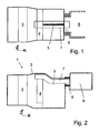
- a motor vehicle air conditioning system 1 with a blower (not shown) arranged in an air guide housing 2, an evaporator 3 and a heater 4 is presently designed as a two-zone air conditioning system with a partition wall 5 extending in the central longitudinal plane (xz plane) Mounting in the air duct housing 2 is used essentially free of play.
- the air conditioner 1 is arranged behind the center console of the motor vehicle.
- a housing 6 hereinafter also partially referred to as electronics housing
- the housing 6 is shown in the drawing highly schematized as a box, but its shape is adapted to the installation space, i. in particular the rear side of the center console and the corresponding region of the air guide housing 2 of the air conditioner 1.
- a cold air bypass starting from a region after the evaporator 3 and in front of the heater 4, provided around the heater 4 around, which is referred to below as the cold air duct 7.
- This cold air duct 7 is formed here unregulated, i. the flow velocity of the air in the cold air duct 7 depends on the blower output.
- a flap can be provided for demand-controlled regulation of the air supply of the electronic components - in particular on the air inlet side.
- the flap can be closed so that the total amount of air is available for removal of the disc fitting.
- the cold air duct 7 in the present case has a substantially circular cross section, as seen from Fig. 4 can be seen, and is integrally integrated into the partition wall 5. It runs - starting from an upper area with respect to the vertical cross-section of the air conditioning - along the central longitudinal plane of the air conditioner 1 above the heater 4.
- the course of the cold air duct 7 follows the same up to its end, in which also the electronics housing is arranged.
- the cold air duct 7 is formed according to the first embodiment, projecting like a nozzle over the air duct housing 2.
- an annular, elastic intermediate element 8 Spaced from the nozzle-shaped end of the cold air duct 7 is an annular, elastic intermediate element 8, in this case formed by a closed-cell, foamed material, both on an outer surface of the air guide housing 2 and on an opposite outer surface of the electronics housing 6 fixedly mounted, for example.
- an annular, elastic intermediate element 8 By gluing, the End of the cold air duct 7 ends approximately at the level of the electronics housing side end of the intermediate element 8.
- the elastic intermediate element 8 serves for a decoupling of air guide housing 2 and electronics housing 6, i. almost no or no vibrations are transmitted from the air conditioner 1 to the center console, on the other hand, the tolerance compensation between the two housings 2 and 6, and further the seal with respect to the air flowing in the cold air duct.
- the air duct 7 is not over the air duct housing 2 nozzle-like over, but ends flush with the air duct housing 2.
- the lbody exteriorsgepuruse sheet provided in the electronics housing 6 opening for the cold air duct 7 is approximately the diameter of the elastic intermediate element 8, which is larger than the outlet opening of the Cold air duct 7 is formed extended, so that the cooling Air flow is already slightly widened in the intermediate element 8 and diffusely enters the electronics housing 6.
- the cold air duct has an approximately square cross-section, wherein the cross-sectional profile over the length of the cold air duct increases in the width direction, so that there is a rectangular outlet opening and the air flow relatively broadly enters the electronics housing.
- the electronics housing according to the present embodiment and the variants thereof is not airtight and has a plurality of gaps and openings, the heated air passes into the area behind the center console and is distributed there.
- an air-tight design of the electronics housing in conjunction with a laxative air duct for example.
- a type of temperature stratification in the vehicle interior ie the temperature in the footwell is above the area arranged above
- Fig. 5 is a second variant with respect to the attachment of the electronics housing 6 on the air guide housing 2 and the introduction of the cold air duct 7 shown in the electronics housing 6.
- the cold air duct 6 is again formed like a nozzle protruding.
- the elastic intermediate element 8 is integrated directly integrated into the air guide housing side wall of the electronics housing 6, for example.
- an annular, elastic intermediate element 8 is attached to the air guide housing 2, for example. Glued. Opposite the air duct housing 2, the electronics housing 6 is attached to the elastic intermediate element 8, for example. Also glued.
- an opening is provided which is larger than the nozzle-like manner on the air guide housing 2 projecting cold air duct 7 is formed. In this case, the end of the cold air duct 7 projects into the electronics housing 6, without the cold air duct 7 touching the electronics housing 6. To avoid noise, a sufficiently large gap between the outer surface of the cold air duct 7 and the inner surface of the opening is provided. For reasons of flow technology and for reinforcing the wall surface of the electronics housing 6, an edge projecting in both sides is formed in the region of the opening.
- Fig. 7 For example, two courses of cold air ducts 7 and 7 'are indicated. For ease of illustration, the elastic intermediate element is not shown. Furthermore, the further course of the cold air duct 7 'to the electronics housing 6 is not shown.
- the Kaftluftkanal 7 extends substantially in the boundary region of the upper outer wall of the air duct housing 2 and the partition wall 5, wherein the cold air duct 7 over part of its circumference from the air duct housing 2 and over the remaining part of its circumference by a correspondingly formed portion of the partition. 5 is formed.
- Downstream cold air duct 7 ' is a course below the heater 4 in the immediate vicinity of the outer wall of the air duct housing 2 integrated into the partition wall 5 and the outer wall provided.
- the transition of the cold air duct 7 'in the direction of the above disposed electronics housing 6 is carried out by a suitable channel guide past the branching off from the air duct housing 2 air channels to the vehicle interior.
- the cold air duct to the electronics housing may alternatively be arranged in a substantially horizontally extending partition wall, for example. When it comes to a four-zone air conditioning.
- the cold air duct is integrated into one of the outer walls of the air duct housing the air conditioning to the electronics housing.
- the cold air duct can be designed to extend above, below or optionally laterally past the heater.
- the cold air duct is at least partially preferably formed integrally with the air duct housing the air conditioning.
- a channel can be attached from the outside to the air duct housing.
- This allows, for example, a kind of modular principle when the air duct housing is formed with a breakable or otherwise removable area for the beginning of the cold air duct.
- the opening may also be closed by means of a flap, which is provided with an actuator only in the case of a cold air duct to the electronics housing or permanently open.
- Another variant with respect to the guidance of the cold air duct provides a split design of the heater.
- the cold air duct can be passed through the gap between the two heating areas.
- the cold air duct can also be formed by a double-walled partition, in particular in connection with a divided embodiment of the heater. This allows a small stream of air to pass into the narrow cold air duct over almost the entire height of the air duct housing and to be guided to the electronic components in the electronics housing.
- a small additional fan can be provided, which operates exclusively in the case of a switched-off air conditioning.
Landscapes
- Physics & Mathematics (AREA)
- Thermal Sciences (AREA)
- Engineering & Computer Science (AREA)
- Mechanical Engineering (AREA)
- Microelectronics & Electronic Packaging (AREA)
- Cooling Or The Like Of Electrical Apparatus (AREA)
- Air-Conditioning For Vehicles (AREA)
- Encapsulation Of And Coatings For Semiconductor Or Solid State Devices (AREA)
Abstract
Description
- Die Erfindung betrifft eine Vorrichtung zur Kühlung von mindestens einem Elektronikbauteil gemäß dem Oberbegriff des Anspruchs 1.
- Um Elektronikbauteile bei Bedarf aktiv zu kühlen, ist es beispielsweise bei Computern bekannt, Lüfter vorzusehen, welche Luft aus der Umgebung ansaugen und dadurch einen Luftstrom vorbei an den Elektronikbauteilen erzeugen, mittels dessen die in den Elektronikbauteilen erzeugte Wärme abgeführt werden kann.
- Aus
EP 0 897 348 B1 ist eine Vorrichtung zur Halterung und Kühlung von elektronischen Einrichtungen in einem Fahrzeug bekannt. Hierbei ist für die Kühlung der elektronischen Einrichtungen ein Luftkanal, über welchen von einem Gebläse kommende Luft zum Verdampfer geführt wird, mit einem klappengeregelten Bypass ausgebildet. An einer Wand des Bypasses sind die elektronischen Vorrichtungen angebracht, die bei Bedarf mittels durch den Bypass leitbarer Luft gekühlt werden. - Derartige Vorrichtungen zur Kühlung von Elektronikbauteilen, insbesondere in Zusammenhang mit Elektronikbauteilen, die in der Mittelkonsole eines Fahrzeugs eingebaut sind, lassen noch Wünsche offen.
- Es ist Aufgabe der Erfindung, eine verbesserte Vorrichtung zur Kühlung von mindestens einem Elektronikbauteil zur Verfügung zu stellen.
- Diese Aufgabe wird gelöst durch eine Vorrichtung zur Kühlung von mindestens einem Elektronikbauteil mit den Merkmalen des Anspruchs 1. Vorteilhafte Ausgestaltungen sind Gegenstand der Unteransprüche.
- Hierbei ist eine Vorrichtung zur Kühlung von mindestens einem Elektronikbauteil, das in einem Elektronikgehäuse angeordnet ist, wobei Teil der Vorrichtung die Kraftfahrzeug-Klimaanlage ist, mit ihrem Luftführungsgehäuse, in welchem ein Verdampfer und ein Heizer angeordnet sind, von dem mindestens ein Luftkanal abzweigt, über welche temperierte Luft einem innenraum zuführbar ist. Hierbei ist mindestens ein Kaltluftkanal vorgesehen, der hinter dem Verdampfer und vor dem Heizer abzweigt, welcher zum Elektronikgehäuse führt und kalte Luft zum Elektronikbauteil führt, so dass dieses ohne wesentlichen, zusätzlichen Aufwand gekühlt werden kann. Im Unterschied zu üblichen Ausgestaltungen ist kein zusätzliches Gebläse erforderlich. Zudem wird gekühlte Luft zum Elektronikbauteil geführt, so dass der Kühlungseffekt - verglichen mit Luft aus der Umgebung - in den meisten Betriebsbedingungen des Fahrzeugs größer ist.
- Insbesondere bevorzugt ist der Kaltluftkanal in eine Trennwand integriert, die im Luftführungsgehäuse für eine Aufteilung des Luftstroms in verschiedene (Klima-)Zonen angeordnet ist. Die Trennwand trennt dabei Bereiche im Luftführungsgehäuse, die unterschiedlich temperierbar sind. Bei der Trennwand kann es sich auch um eine Trennwand zwischen einem kaltluftführenden und einen warmluftführenden Kanal im Luftführungsgehäuse handeln. Alternativ oder in Kombination hiermit kann der Kaltluftkanal auch ganz oder teilweise in eine Wand des Luftführungsgehäuses integriert sein.
- Bevorzugt ist das Elektronikbauteil in einem Elektronikgehäuse angeordnet, welches mit dem Luftführungsgehäuse der Klimaanlage über den Kaltluftkanal verbunden ist. Hierbei kann eine direkte Verbindung zwischen Elektronikgehäuse und Luftführungsgehäuse vorgesehen sein, jedoch ist bevorzugt ein elastisches Zwischenelement zwischen den beiden Gehäusen angeordnet oder zumindest ein elastischer Bereich an einem der beiden Gehäuse vorgesehen, welcher die beiden Gehäuse entkoppelt, so dass eine Übertragung von Schwingungen verhindert wird.
- Der elastische Bereich kann durch einen Teilbereich einer Wand des Elektronikgehäuses gebildet sein, in welchen ein über das Luftführungsgehäuse überstehender Bereich des Kaltluftkanals eindringt. Hierbei ist bevorzugt der Öffnungsquerschnitt des elastischen Teilbereichs kleiner als der Außenquerschnitt des überstehenden Kaltluftkanals, wobei der Querschnitt nicht notwendigerweise kreisförmig sein muss. Bevorzugt erfolgt die Herstellung des Elektronikgehäuses mittels eines Zwei-Komponenten-Spritzgussverfahrens, wobei der elastische Teilbereich auch nachträglich angespritzt sein kann. Der elastische Teilbereich kann auch durch ein getrennt ausgebildetes elastisches Zwischenelement gebildet sein, welches in eine größere Öffnung in der Wand eingesetzt ist.
- Alternativ kann das elastische Zwischenelement mit einer Fläche fest an einer Außenfläche des Luftführungsgehäuses angebracht und mit der gegenüberliegenden Fläche fest mit einer Wand des Elektronikgehäuses verbunden sein. Zusätzlich kann ein über das Luftführungsgehäuse überstehender Bereich des Kaltluftkanals berührungslos in das Elektronikgehäuses eindringen.
- Das Elektronikgehäuse, in welchem das mindestens eine Elektronikbauteil oder zumindest mit einem wärmeerzeugenden und/oder abgebenden Bereich angeordnet ist, ist vorzugsweise im Bereich der Mittelkonsole eines Fahrzeugs angeordnet. Dies ermöglicht ohne Veränderung der herkömmlichen Einbaulage der Klimaanlage eine kurze Wegführung des Kaltluftkanals bis zu seinem Zielort.
- Insbesondere bevorzugt ist der Kaltluftkanal einstückig mit der Trennwand und/oder dem Luftführungsgehäuse ausgebildet, insbesondere bevorzugt spritzgegossen. Durch eine einstückige Ausgestaltung verringert sich die Anzahl der im Rahmen der Montage zusammenzubauenden Teile, so dass sich der Montageaufwand verringert.
- In einer weiteren bevorzugten Ausführungsform, ist das Elektronikbauteil in einem offenen, beispielsweise ein- oder zweiseitig offenen Elektronikgehäuse angeordnet, so dass eine direkte Verbindung über den Kaltluftkanal oder das Luftführungsgehäuse entfallen kann und der Kaftluftkanal vor oder zu einem Anströmbereich an dem offenen Gehäuse geführt ist. Zwischen den beiden Gehäusen kann damit ein elastisches Zwischenelement entfallen.
- In einer weiteren vorteilhaften Variante ist das Elektronikbauteil ohne ein dieses ganz oder teilweise umschließendes Gehäuse, beispielsweise an einer Wand angeordnet wobei der Kaltluftkanal hin zu einem Anströmbereich dieser Wand mit dem Elektronikbauteil führt. Alternativ ist auch die Anordnung des Elektronikbauteils in einem einseitig
- Im Folgenden wird die Erfindung anhand mehrerer Ausführungsbeispiele, teilweise mit Varianten und unter Bezugnahme auf die Zeichnung, im Einzelnen erläutert. Es zeigen:
- Fig. 1
- eine schematische Darstellung eines Längsschnitts in horizontaler Ebene (xy-Ebene) einer Klimaanlage samt angedeutetem Elektronikgehäuse gemäß dem ersten Ausführungsbeispiel,
- Fig. 2
- eine schematische Darstellung eines Längsschnitts in vertikaler Ebene (xz-Ebene) der Klimaanlage samt Elektronikgehäuse von
Fig. 1 , - Fig.3
- eine schematisierte Detaildarstellung des Übergangsbereichs von Klimaanlage zum Elektronikgehäuse gemäß einer leicht abgewandelten Variante des ersten Ausführungsbeispiels,
- Fig. 4
- eine ausschnittsweise Detaildarstellung einer Trennwand, wie sie bei der Klimaanlage von
Fig. 1 verwendet wird, - Fig. 5
- eine schematisierte Detaildarstellung des Übergangsbereichs von Klimaanlage zum Elektronikgehäuse gemäß einer zweiten Variante,
- Fig. 6
- eine schematisierte Detaildarstellung des Übergangsbereichs von Klimaanlage zum Elektronikgehäuse gemäß einer dritten Variante, und
- Fig. 7
- eine schematische Darstellung eines Längsschnitts in horizontaler Ebene einer Klimaanlage samt angedeutetem Elektronikgehäuse zur Verdeutlichung zweier gestrichelt dargestellter, alternativer Verläufe eines in die Mitteltrennwand integrierten Kaltluftkanals zum Elektronikgehäuse.
- Eine Kraftfahrzeug-Klimaanlage 1 mit einem in einem Luftführungsgehäuse 2 angeordneten Gebläse (nicht dargestellt), einem Verdampfer 3 und einem Heizer 4 ist vorliegend als zweizonige Klimaanlage mit einer in der Mittellängsebene (xz-Ebene) verlaufenden Trennwand 5 ausgebildet, welche vorliegend im Rahmen der Montage in das Luftführungsgehäuse 2 im wesentlichen spielfrei eingesetzt wird. Im eingebauten Zustand ist die Klimaanlage 1 hinter der Mittelkonsole des Kraftfahrzeugs angeordnet.
- In der Mittelkonsole sind ferner Elektronikbauteile (nicht im Einzelnen dargestellt) vorgesehen, welche vorliegend zumindest mit ihrem wärmeerzeugenden Bereich in einem Gehäuse 6, im Folgenden teilweise auch als Elektronikgehäuse bezeichnet, angeordnet sind. Das Gehäuse 6 ist in der Zeichnung stark schematisiert als Kasten dargestellt, jedoch ist seine Gestalt dem Bauraum angepasst, d.h. insbesondere der Rückseite der Mittelkonsole und dem entsprechenden Bereich des Luftführungsgehäuses 2 der Klimaanlage 1.
- Um die im und am Gehäuse 6 angebrachten Elektronikbauteile zu kühlen, ist ein Kaltluftbypass, ausgehend von einem Bereich nach dem Verdampfer 3 und vor dem Heizer 4, um den Heizer 4 herum vorgesehen, der im Folgenden als Kaltluftkanal 7 bezeichnet ist. Dieser Kaltluftkanal 7 ist vorliegend ungeregelt ausgebildet, d.h. die Strömungsgeschwindigkeit der Luft im Kaltluftkanal 7 hängt von der Gebläseleistung ab.
- Alternativ kann - insbesondere lufteintrittsseitig - eine Klappe für eine bedarfsgerechte Regelung der Luftversorgung der Elektronikbauteile vorgesehen sein. Beispielsweise für den Defrostbetrieb kann die Klappe geschlossen werden, damit die gesamte Luftmenge für eine Entfernung des Scheibenbeschlags zur Verfügung steht.
- Der Kaltluftkanal 7 weist vorliegend einen im Wesentlichen kreisförmigen Querschnitt auf, wie aus
Fig. 4 ersichtlich, und ist einstückig in die Trennwand 5 integriert. Er verläuft - ausgehend von einem oberen Bereich in Bezug auf den vertikalen Querschnitt der Klimaanlage - entlang der Mittellängsebene der Klimaanlage 1 oberhalb des Heizers 4. In Anpassung an den Verlauf des Luftführungsgehäuses 2 folgt der Verlauf des Kaltluftkanals 7 demselben bis zu dessen Endbereich, in welchem auch das Elektronikgehäuse angeordnet ist. Der Kaltluftkanal 7 ist gemäß dem ersten Ausführungsbeispiel stutzenartig überstehend über das Luftführungsgehäuse 2 ausgebildet. Beabstandet vom stutzenförmigen Ende des Kaltluftkanals 7 ist ein ringförmiges, elastisches Zwischenelement 8, vorliegend gebildet durch ein geschlossenzelliges, geschäumtes Material, sowohl an einer Außenfläche des Luftführungsgehäuses 2 als auch an einer gegenüberliegenden Außenfläche des Elektronikgehäuses 6 fest angebracht, bspw. mittels Klebens, wobei das Ende des Kaltluftkanals 7 etwa in Höhe des elektronikgehäuseseitigen Endes des Zwischenelements 8 endet. - Das elastische Zwischenelement 8 dient zum einen der Entkopplung von Luftführungsgehäuse 2 und Elektronikgehäuse 6, d.h. fast keine oder keine Schwingungen werden von der Klimaanlage 1 an die Mittelkonsole übertragen, zum anderen dem Toleranzausgleich zwischen dem beiden Gehäusen 2 und 6, und des weiteren der Abdichtung in Bezug auf die im Kaltluftkanal strömende Luft.
- Gemäß einer in
Fig. 3 dargestellten Variante, steht der Kaltluftkanal 7 nicht über das Luftführungsgehäuse 2 stutzenartig über, sondern endet bündig mit dem Luftführungsgehäuse 2. Die lüftführungsgehäuseseitig im Elektronikgehäuse 6 vorgesehene Öffnung für den Kaltluftkanal 7 ist auf etwa den Durchmesser des elastischen Zwischenelements 8, der größer als die Austrittsöffnung des Kaltluftkanals 7 ist, erweitert ausgebildet, so dass der kühlende Luftstrom bereits im Zwischenelement 8 etwas aufgeweitet wird und diffus in das Elektronikgehäuse 6 eintritt. - Gemäß einer nicht in der Zeichnung dargestellten Variante weist der Kaltluftkanal einen etwa quadratischen Querschnitt auf, wobei der Querschnittsverlauf über die Länge des Kaltluftkanals sich in Breitenrichtung vergrößert, so dass sich eine rechteckförmige Austrittsöffnung ergibt und der Luftstrom relativ breitflächig in das Elektronikgehäuse eintritt.
- Da das Elektronikgehäuse gemäß dem vorliegenden Ausführungsbeispiel und der Varianten hierzu nicht luftdicht ausgebildet ist und eine Mehrzahl von Spalte und Öffnungen aufweist, gelangt die erwärmte Luft in den Bereich hinter der Mittelkonsole und verteilt sich dort.
- Alternativ ist auch eine luftdichte Ausgestaltung des Elektronikgehäuses in Verbindung mit einem abführenden Luftkanal, bspw. zum Fußraum (bei starker Wärmeabgabe der Elektronikbauteile ergibt sich so automatisch eine Art Temperaturschichtung im Fahrzeuginnenraum, d.h. die Temperatur im Bereich des Fußraums liegt über der im darüber angeordneten Bereich) oder zur Umgebung hin möglich.
- In
Fig. 5 ist eine zweite Variante in Bezug auf die Anbringung des Elektronikgehäuses 6 am Luftführungsgehäuse 2 und die Einführung des Kaltluftkanals 7 in das Elektronikgehäuse 6 dargestellt. Hierbei ist der Kaltluftkanal 6 wieder stutzenartig überstehend ausgebildet. Im Unterschied zum ersten Ausführungsbeispiel ist jedoch das elastische Zwischenelement 8 direkt integriert in die luftführungsgehäuseseitige Wand des Elektronikgehäuses 6 integriert ausgebildet, bspw. mittels eines Zwei-Komponenten-Spritzgußverfahrens. Das stutzenartige Ende des Kaltluftkanals 7 ist in eine in dem Zwischenelement 8 ausgebildete Öffnung unter leichter Vorspannung aufgenommen, so dass die Innenfläche des Zwischenelements 8 flächig am Außenumfang des stutzenartigen Endes anliegt und ein Austreten von Luft verhindert wird. - Gemäß der in
Fig. 6 dargestellten, dritten Variante in Bezug auf die Anbringung des Elektronikgehäuses 6 am Luftführungsgehäuse 2 ist am Luftführungsgehäuse 2 ein ringförmiges, elastisches Zwischenelement 8 angebracht, bspw. angeklebt. Gegenüberliegend vom Luftführungsgehäuse 2 ist das Elektronikgehäuse 6 am elastischen Zwischenelement 8 angebracht, bspw. ebenfalls angeklebt. In der Seitenwand des Elektronikgehäuses 6 ist eine Öffnung vorgesehen, die größer als der stutzenartig über das Luftführungsgehäuse 2 überstehende Kaltluftkanal 7 ausgebildet ist. Dabei ragt das Ende des Kaltluftkanals 7 bis in das Elektronikgehäuse 6 hinein, ohne dass der Kaltluftkanal 7 das Elektronikgehäuse 6 berührt. Zur Vermeidung von Geräuschen ist ein ausreichend großer Spalt zwischen der Außenfläche des Kaltluftkanals 7 und der Innenfläche der Öffnung vorgesehen. Aus strömungstechnischen Gründen sowie zur Verstärkung der Wandfläche des Elektronikgehäuses 6 ist im Bereich der Öffnung ein in beide Seiten vorstehender Rand ausgebildet. - In
Fig. 7 sind beispielhaft zwei Verläufe von Kaltluftkanälen 7 bzw. 7' angedeutet. Zur Vereinfachung der Darstellung ist das elastische Zwischenelement nicht dargestellt. Ferner ist der weitere Verlauf des Kaltluftkanals 7' zum Elektronikgehäuse 6 nicht dargestellt. - Wie in
Fig. 7 , oben dargestellt, verläuft der Kaftluftkanal 7 im Wesentlichen im Grenzbereich der oberen Außenwand des Luftführungsgehäuses 2 und der Trennwand 5, wobei der Kaltluftkanal 7 über einen Teil seines Umfangs vom Luftführungsgehäuse 2 und über den restlichen Teil seines Umfangs durch einen entsprechend ausgebildeten Bereich der Trennwand 5 gebildet ist. - Gemäß dem in
Fig. 7 , unten dargestellten Kaltluftkanal 7' ist ein Verlauf unterhalb des Heizers 4 in direkter Nachbarschaft zur Außenwand des Luftführungsgehäuses 2 integriert in die Trennwand 5 und die Außenwand vorgesehen. Die Überleitung des Kaltluftkanals 7' in Richtung des oberhalb angeordneten Elektronikgehäuses 6 erfolgt durch eine geeignete Kanalführung vorbei an den vom Luftführungsgehäuse 2 abzweigenden Luftkanälen zum Fahrzeuginnenraum. - Der Kaltluftkanal zum Elektronikgehäuse kann alternativ auch in einer im Wesentlichen horizontal verlaufenden Trennwand angeordnet sein, bspw. wenn es sich um eine vierzonige Klimaanlage handelt.
- Gemäß einem zweiten, nicht in der Zeichnung dargestellten Ausführungsbeispiel verläuft der Kaltluftkanal integriert in eine der Außenwände des Luftführungsgehäuses der Klimaanlage zum Elektronikgehäuse. Der Kaltluftkanal kann - je nach vorhandenem Bauraum - oberhalb, unterhalb oder ggf. auch seitlich am Heizer vorbei verlaufend ausgestaltet sein. Hierbei ist der Kaltluftkanal zumindest bereichsweise bevorzugt einstückig mit dem Luftführungsgehäuse der Klimaanlage ausgebildet.
- Gemäß einer Variante kann jedoch auch ein Kanal von außen an das Luftführungsgehäuse angebracht werden. Dies ermöglicht beispielsweise eine Art Baukastenprinzip, wenn das Luftführungsgehäuse mit einem herausbrechbaren oder auf andere Weise entfernbaren Bereich für den Beginn des Kaltluftkanals ausgebildet ist. Hierbei kann die Öffnung auch mittels einer Klappe verschlossen sein, die nur im Falle eines Kaltluftkanals zum Elektronikgehäuse mit einem Aktuator versehen oder beständig geöffnet ist.
- Eine weitere Variante in Bezug auf die Führung des Kaltluftkanals bietet eine geteilte Ausgestaltung des Heizers. In diesem Fall kann der Kaltluftkanal durch die Lücke zwischen den beiden Heizbereichen geführt werden.
- Der Kaltluftkanal kann - insbesondere in Verbindung mit einer geteilten Ausgestaltung des Heizers - auch durch eine doppelwandige Trennwand gebildet sein. Dies ermöglicht, dass über nahezu die gesamte Höhe des Luftführungsgehäuses ein kleiner Luftstrom in den schmalen Kaltluftkanal gelangen und zu den Elektronikbauteilen im Elektronikgehäuse geführt werden kann.
- Um auch im Falle einer ausgeschalteten Klimaanlage eine Kühlung der Elektronikbauteile sicherstellen zu können, werden im Falle eines manuellen Ausschalten der Klimaanlage bzw. des Gebläses derselben lediglich alle Luftausgänge zum Fahrzeuginnenraum durch Klappen verschlossen. Das Gebläse läuft - ggf. mit minimaler Drehzahl - weiter, um weiter für eine Kühlung der Elektronikbauteile zu sorgen.
- Alternativ kann auch ein kleiner Zusatzlüfter vorgesehen sein, der ausschließlich im Falle einer ausgeschalteten Klimaanlage tätig wird.
-
- 1
- Klimaanlage
- 2
- Luftführungsgehäuse
- 3
- Verdampfer
- 4
- Heizer
- 5
- Trennwand
- 6
- Gehäuse, Elektronikgehäuse
- 7, 7'
- Kaltluftkanal
- 8
- Zwischenelement
Claims (15)
- Vorrichtung zur Kühlung von mindestens einem Elektronikbauteil, aufweisend eine Klimaanlage (1), insbesondere Kraftfahrzeug-Klimaanlage (1), mit einem Luftführungsgehäuse (2), in welchem ein Verdampfer (3) und ein Heizer (4) angeordnet sind, und von dem mindestens ein Luftkanal abzweigt, über welchen temperierte Luft einem Innenraum zuführbar ist, dadurch gekennzeichnet, dass ein Kaltluftkanal (7, 7') vorgesehen ist, der hinter dem Verdampfer (3) und vor dem Heizer (4) abzweigt, welcher zum Elektronikbauteil führt.
- Vorrichtung nach Anspruch 1, dadurch gekennzeichnet, dass der Kaltluftkanal (7, 7') in eine Trennwand (5) integriert ist, die im Luftführungsgehäuse (2) angeordnet ist.
- Vorrichtung nach Anspruch 1 oder 2, dadurch gekennzeichnet, dass der Kaltluftkanal (7, 7') in eine Wand des Luftführungsgehäuses (2) integriert ist.
- Vorrichtung nach einem der vorhergehenden Ansprüche, dadurch gekennzeichnet, dass das Elektronikbauteil in einem Elektronikgehäuse (6) angeordnet ist, welches mit dem Luftführungsgehäuse (2) der Klimaanlage (1) über den Kaltluftkanal (7, 7') verbunden ist.
- Vorrichtung nach Anspruch 4, dadurch gekennzeichnet, dass das Elektronikgehäuse (6) und das Luftführungsgehäuse (2) über einen elastisch ausgebildeten Bereich oder ein elastisches Zwischenelement (8) miteinander verbunden sind.
- Vorrichtung nach Anspruch 5, dadurch gekennzeichnet, dass der elastische Bereich durch einen Teilbereich einer Wand des Elektronikgehäuses (6) gebildet ist, in welchen ein über das Luftführungsgehäuse (2) überstehender Bereich des Kaltluftkanals (7, 7') eindringt.
- Vorrichtung nach Anspruch 5, dadurch gekennzeichnet, dass das elastische Zwischenelement (8) mit einer Fläche fest an einer Außenfläche des Luftführungsgehäuses (2) angebracht und mit der gegenüberliegenden Fläche fest mit einer Wand des Elektrohikgehäuses (6) verbunden ist, und dass ein über das Luftführungsgehäuse (2) überstehender Bereich des Kaltluftkanals (7, 7') berührungslos in das Elektronikgehäuses (6) eindringt.
- Vorrichtung nach einem der vorhergehenden Ansprüche, dadurch gekennzeichnet, dass der Kaftluftkanal (7, 7') einstückig mit dem Luftführungsgehäuse (2) und/oder der Trennwand (5) im Luftführungsgehäuse (2) ausgebildet ist.
- Vorrichtung nach einem der vorhergehenden Ansprüche, dadurch gekennzeichnet, dass das Elektronikbauteil im Bereich der Mittelkonsole eines Fahrzeugs angeordnet ist.
- Vorrichtung nach Anspruch 9, dadurch gekennzeichnet, dass das Elektronikbauteil in einem Elektronikgehäuse (6) angeordnet ist, welches unterhalb der Mittelkonsole des Fahrzeugs angeordnet ist, und in welchem der Kaltluftkanal (7, 7') endet.
- Vorrichtung nach einem der vorhergehenden Ansprüche, dadurch gekennzeichnet, dass der Kaltluftkanal (7, 7') einstückig spritzgegossen mit der Trennwand (5) und/oder dem Luftführungsgehäuse (2) ist.
- Verfahren zum Betreiben einer Vorrichtung nach einem der vorhergehenden Ansprüche, die eine Kühlung des Elektronikbauteils über einen Kaltluftkanal (7, 7') vorsieht, über welchen vom Gebläse geförderte und vom Verdampfer (3) kommende Kaltluft zum Elektronikbauteil geleitet wird.
- Verfahren nach Anspruch 12, dadurch gekennzeichnet, dass im Falle einer Abschaltung der Klimaanlage (1) eine Zwangsbelüftung des Elektronikbauteils im Bedarfsfall vorgesehen ist.
- Verfahren nach Anspruch 13, dadurch gekennzeichnet, dass die Zwangsbelüftung über das Gebläse der Klimaanlage (1) erfolgt, und sämtliche Luftkanäle zum Innenraum verschlossen werden.
- Verfahren nach Anspruch 13, dadurch gekennzeichnet, dass die Zwangsbelüftung durch einen kleinen Zusatzlüfter erfolgt, der bei stehendem Gebläse angeschaltet wird.
Applications Claiming Priority (1)
| Application Number | Priority Date | Filing Date | Title |
|---|---|---|---|
| DE102007029635A DE102007029635A1 (de) | 2007-06-26 | 2007-06-26 | Vorrichtung zur Kühlung von Elektronikbauteilen |
Publications (2)
| Publication Number | Publication Date |
|---|---|
| EP2008840A1 true EP2008840A1 (de) | 2008-12-31 |
| EP2008840B1 EP2008840B1 (de) | 2010-11-24 |
Family
ID=39830224
Family Applications (1)
| Application Number | Title | Priority Date | Filing Date |
|---|---|---|---|
| EP08011559A Not-in-force EP2008840B1 (de) | 2007-06-26 | 2008-06-26 | Vorrichtung zur Kühlung von Elektronikbautteilen |
Country Status (3)
| Country | Link |
|---|---|
| EP (1) | EP2008840B1 (de) |
| AT (1) | ATE489246T1 (de) |
| DE (2) | DE102007029635A1 (de) |
Cited By (2)
| Publication number | Priority date | Publication date | Assignee | Title |
|---|---|---|---|---|
| CN110461135A (zh) * | 2019-08-30 | 2019-11-15 | 江苏华频电子科技有限公司 | 一种电动工具散热系统及集成化散热系统 |
| US11505033B2 (en) | 2019-11-08 | 2022-11-22 | Volvo Car Corporation | Module for accommodating and cooling electronic circuitry in a vehicle |
Families Citing this family (3)
| Publication number | Priority date | Publication date | Assignee | Title |
|---|---|---|---|---|
| DE102012203351A1 (de) * | 2012-03-02 | 2013-09-05 | Behr Gmbh & Co. Kg | Kraftfahrzeugklimaanlage |
| DE102012204892A1 (de) * | 2012-03-27 | 2013-10-02 | Mekra Lang Gmbh & Co. Kg | Temperierbares Gehäuse zur Aufnahme einer elektronischen Einrichtung und Fahrzeug mit diesem Gehäuse |
| DE102012021445A1 (de) | 2012-10-31 | 2013-05-02 | Daimler Ag | Vorrichtung zur Kühlung von Elektronikkomponenten in einem Kraftfahrzeug |
Citations (4)
| Publication number | Priority date | Publication date | Assignee | Title |
|---|---|---|---|---|
| EP0897348B1 (de) | 1996-05-03 | 2001-10-24 | Ford Motor Company Limited | Vorrichtung zur halterung und kühlung von elktronischen einrichtungen in einem fahrzeug |
| DE10359064B3 (de) * | 2003-12-17 | 2005-03-10 | Daimler Chrysler Ag | Kühlungseinrichtung zur Kühlung elektronischer Bauteile in einem Kraftfahrzeug |
| DE102005050683A1 (de) * | 2004-10-21 | 2006-05-18 | Behr Gmbh & Co. Kg | Vorrichtung zur Kühlung einer Wärmequelle eines Kraftfahrzeugs |
| DE102005013567A1 (de) * | 2005-03-23 | 2006-09-28 | Siemens Ag | Anordnung zur Kühlung von Komponenten in einem Fahrzeug |
Family Cites Families (11)
| Publication number | Priority date | Publication date | Assignee | Title |
|---|---|---|---|---|
| DE3331890A1 (de) * | 1983-09-03 | 1985-03-28 | Süddeutsche Kühlerfabrik Julius Fr. Behr GmbH & Co KG, 7000 Stuttgart | Kraftfahrzeug-heizungs- und/oder klimaanlage |
| US4976327A (en) * | 1989-02-14 | 1990-12-11 | Globe-Union Inc. | Battery module for the engine compartment of an automobile |
| FR2646500B1 (fr) * | 1989-04-27 | 1994-11-25 | Alsthom Gec | Procede de refroidissement de composants electriques, dispositif pour la mise en oeuvre de ce procede et application aux composants embarques dans un vehicule |
| US20030193217A1 (en) * | 1996-08-13 | 2003-10-16 | Mollertech Gmbh | Motor vehicle passenger compartment heat insulation and dissipation |
| DE19821683B4 (de) * | 1997-05-26 | 2006-07-06 | Volkswagen Ag | Anordnung zur Kühlung eines in eine Fahrzeugkabine eingebauten elektronischen Geräts |
| DE10009521A1 (de) * | 2000-02-29 | 2001-08-30 | Mannesmann Sachs Ag | Elektrisches System |
| FR2832023B1 (fr) * | 2001-11-02 | 2004-02-20 | Valeo Climatisation | Module de commande de groupe moto-ventilateur |
| DE10160935A1 (de) * | 2001-12-12 | 2003-07-17 | Daimler Chrysler Ag | Kraftfahrzeugkühlvorrichtung für elektronische Geräte |
| DE20213397U1 (de) * | 2002-08-30 | 2003-01-09 | TRW Automotive Electronics & Components GmbH & Co.KG, 67677 Enkenbach-Alsenborn | Baugruppe zur Kühlung eines Steuermoduls und einer Batterie |
| DE102004028740B4 (de) * | 2004-06-14 | 2007-09-27 | Lisa Dräxlmaier GmbH | Kombiniertes Kühl-/Klimasystem für Kraftfahrzeuge |
| DE102004051608A1 (de) * | 2004-10-23 | 2006-04-27 | Bayerische Motoren Werke Ag | Kühleinrichtung für Fahrzeuge |
-
2007
- 2007-06-26 DE DE102007029635A patent/DE102007029635A1/de not_active Withdrawn
-
2008
- 2008-06-26 EP EP08011559A patent/EP2008840B1/de not_active Not-in-force
- 2008-06-26 AT AT08011559T patent/ATE489246T1/de active
- 2008-06-26 DE DE502008001864T patent/DE502008001864D1/de active Active
Patent Citations (4)
| Publication number | Priority date | Publication date | Assignee | Title |
|---|---|---|---|---|
| EP0897348B1 (de) | 1996-05-03 | 2001-10-24 | Ford Motor Company Limited | Vorrichtung zur halterung und kühlung von elktronischen einrichtungen in einem fahrzeug |
| DE10359064B3 (de) * | 2003-12-17 | 2005-03-10 | Daimler Chrysler Ag | Kühlungseinrichtung zur Kühlung elektronischer Bauteile in einem Kraftfahrzeug |
| DE102005050683A1 (de) * | 2004-10-21 | 2006-05-18 | Behr Gmbh & Co. Kg | Vorrichtung zur Kühlung einer Wärmequelle eines Kraftfahrzeugs |
| DE102005013567A1 (de) * | 2005-03-23 | 2006-09-28 | Siemens Ag | Anordnung zur Kühlung von Komponenten in einem Fahrzeug |
Cited By (3)
| Publication number | Priority date | Publication date | Assignee | Title |
|---|---|---|---|---|
| CN110461135A (zh) * | 2019-08-30 | 2019-11-15 | 江苏华频电子科技有限公司 | 一种电动工具散热系统及集成化散热系统 |
| CN110461135B (zh) * | 2019-08-30 | 2024-04-30 | 江苏华频电子科技有限公司 | 一种电动工具散热系统及集成化散热系统 |
| US11505033B2 (en) | 2019-11-08 | 2022-11-22 | Volvo Car Corporation | Module for accommodating and cooling electronic circuitry in a vehicle |
Also Published As
| Publication number | Publication date |
|---|---|
| DE102007029635A1 (de) | 2009-01-08 |
| ATE489246T1 (de) | 2010-12-15 |
| EP2008840B1 (de) | 2010-11-24 |
| DE502008001864D1 (de) | 2011-01-05 |
Similar Documents
| Publication | Publication Date | Title |
|---|---|---|
| DE60225979T2 (de) | Vorrichtung zur Erzeugung einer temperaturgeregelten Luftströmung für einen Kraftfahrzeugfahrgastraum und Heizungs- und/oder Klimaanlage mit einer solchen Sicherungsvorrichtung | |
| DE69500706T2 (de) | Bedienungsvorrichtung für die Klimaanlage eines Kraftfahrzeuges | |
| EP2038154B1 (de) | Schienenfahrzeug mit einer kühlanordnung für in einem unterflurbereich angeordnete komponenten | |
| DE69301785T2 (de) | Vorrichtung für die Heizung, Lüftung und/oder Klimatisierung eines Fahrzeuginnenraumes | |
| EP2008840B1 (de) | Vorrichtung zur Kühlung von Elektronikbautteilen | |
| DE19920061C1 (de) | Heizungs- oder Klimaanlage für eine Fahrgastzelle eines Kraftfahrzeugs | |
| DE102019207567A1 (de) | Luftausströmer für den Innenraum eines Kraftfahrzeugs | |
| EP1641642B1 (de) | Kraftfahrzeug-klimaanlage | |
| DE102005013567A1 (de) | Anordnung zur Kühlung von Komponenten in einem Fahrzeug | |
| DE19515836B4 (de) | Heizungs- und Belüftungsvorrichtung für Innenräume von Fahrzeugen | |
| DE10062151B4 (de) | Instrumententafel, insbesondere für ein Kraftfahrzeug, mit einem Grundkörper und einer Abdeckung | |
| EP1426213A2 (de) | Klimagerät für Fahrzeuge | |
| DE102012214859A1 (de) | Klimaanlage, insbesondere für ein Kraftfahrzeug | |
| EP0089500A1 (de) | Gehäuse für eine Heizungs- oder Klimaanlage für Kraftfahrzeuge | |
| EP3144180A1 (de) | Belüftungseinrichtung und sitz mit einer solchen belüftungseinrichtung, insbesondere für ein fahrzeug | |
| EP1930193B1 (de) | Vorrichtung zur Luftmengenregelung, insbesondere für eine Kraftfahrzeug-Klimaanlage | |
| DE10350193A1 (de) | Fahrzeug-Klimaanlage | |
| WO2001040002A9 (de) | Heiz- und/oder klimaanlage für ein fahrzeug mit teilluftführungskanal | |
| DE102008038935A1 (de) | Heiz- und Lüftungseinheit für ein Fahrzeug mit minimalem Energieverbrauch | |
| DE1284317C2 (de) | Heiz- und belueftungsvorrichtung, insbesondere fuer kraftfahrzeuge | |
| DE102018118234B4 (de) | Luftausströmer | |
| DE102024106861B3 (de) | Luftausströmersystem für ein fahrzeug | |
| EP2407324B1 (de) | Luftregulierungselement für eine Heizungs- und Belüftungsvorrichtung für ein Kraftfahrzeug sowie Heizungs- und Belüftungsvorrichtung für einen Fahrgastraum eines Kraftfahrzeuges | |
| EP1843908B1 (de) | Kraftfahrzeug-klimaanlage | |
| DE19956038B4 (de) | Belüftungsvorrichtung für ein Gehäuse |
Legal Events
| Date | Code | Title | Description |
|---|---|---|---|
| PUAI | Public reference made under article 153(3) epc to a published international application that has entered the european phase |
Free format text: ORIGINAL CODE: 0009012 |
|
| AK | Designated contracting states |
Kind code of ref document: A1 Designated state(s): AT BE BG CH CY CZ DE DK EE ES FI FR GB GR HR HU IE IS IT LI LT LU LV MC MT NL NO PL PT RO SE SI SK TR |
|
| AX | Request for extension of the european patent |
Extension state: AL BA MK RS |
|
| 17P | Request for examination filed |
Effective date: 20090630 |
|
| 17Q | First examination report despatched |
Effective date: 20090729 |
|
| AKX | Designation fees paid |
Designated state(s): AT BE BG CH CY CZ DE DK EE ES FI FR GB GR HR HU IE IS IT LI LT LU LV MC MT NL NO PL PT RO SE SI SK TR |
|
| GRAP | Despatch of communication of intention to grant a patent |
Free format text: ORIGINAL CODE: EPIDOSNIGR1 |
|
| GRAS | Grant fee paid |
Free format text: ORIGINAL CODE: EPIDOSNIGR3 |
|
| GRAA | (expected) grant |
Free format text: ORIGINAL CODE: 0009210 |
|
| AK | Designated contracting states |
Kind code of ref document: B1 Designated state(s): AT BE BG CH CY CZ DE DK EE ES FI FR GB GR HR HU IE IS IT LI LT LU LV MC MT NL NO PL PT RO SE SI SK TR |
|
| REG | Reference to a national code |
Ref country code: GB Ref legal event code: FG4D Free format text: NOT ENGLISH |
|
| REG | Reference to a national code |
Ref country code: CH Ref legal event code: EP |
|
| REG | Reference to a national code |
Ref country code: IE Ref legal event code: FG4D |
|
| REF | Corresponds to: |
Ref document number: 502008001864 Country of ref document: DE Date of ref document: 20110105 Kind code of ref document: P |
|
| REG | Reference to a national code |
Ref country code: NL Ref legal event code: VDEP Effective date: 20101124 |
|
| LTIE | Lt: invalidation of european patent or patent extension |
Effective date: 20101124 |
|
| PG25 | Lapsed in a contracting state [announced via postgrant information from national office to epo] |
Ref country code: NO Free format text: LAPSE BECAUSE OF FAILURE TO SUBMIT A TRANSLATION OF THE DESCRIPTION OR TO PAY THE FEE WITHIN THE PRESCRIBED TIME-LIMIT Effective date: 20110224 Ref country code: LT Free format text: LAPSE BECAUSE OF FAILURE TO SUBMIT A TRANSLATION OF THE DESCRIPTION OR TO PAY THE FEE WITHIN THE PRESCRIBED TIME-LIMIT Effective date: 20101124 |
|
| PG25 | Lapsed in a contracting state [announced via postgrant information from national office to epo] |
Ref country code: SI Free format text: LAPSE BECAUSE OF FAILURE TO SUBMIT A TRANSLATION OF THE DESCRIPTION OR TO PAY THE FEE WITHIN THE PRESCRIBED TIME-LIMIT Effective date: 20101124 Ref country code: FI Free format text: LAPSE BECAUSE OF FAILURE TO SUBMIT A TRANSLATION OF THE DESCRIPTION OR TO PAY THE FEE WITHIN THE PRESCRIBED TIME-LIMIT Effective date: 20101124 Ref country code: CY Free format text: LAPSE BECAUSE OF FAILURE TO SUBMIT A TRANSLATION OF THE DESCRIPTION OR TO PAY THE FEE WITHIN THE PRESCRIBED TIME-LIMIT Effective date: 20101124 Ref country code: SE Free format text: LAPSE BECAUSE OF FAILURE TO SUBMIT A TRANSLATION OF THE DESCRIPTION OR TO PAY THE FEE WITHIN THE PRESCRIBED TIME-LIMIT Effective date: 20101124 Ref country code: HR Free format text: LAPSE BECAUSE OF FAILURE TO SUBMIT A TRANSLATION OF THE DESCRIPTION OR TO PAY THE FEE WITHIN THE PRESCRIBED TIME-LIMIT Effective date: 20101124 Ref country code: LV Free format text: LAPSE BECAUSE OF FAILURE TO SUBMIT A TRANSLATION OF THE DESCRIPTION OR TO PAY THE FEE WITHIN THE PRESCRIBED TIME-LIMIT Effective date: 20101124 Ref country code: BG Free format text: LAPSE BECAUSE OF FAILURE TO SUBMIT A TRANSLATION OF THE DESCRIPTION OR TO PAY THE FEE WITHIN THE PRESCRIBED TIME-LIMIT Effective date: 20110224 Ref country code: PT Free format text: LAPSE BECAUSE OF FAILURE TO SUBMIT A TRANSLATION OF THE DESCRIPTION OR TO PAY THE FEE WITHIN THE PRESCRIBED TIME-LIMIT Effective date: 20110324 Ref country code: NL Free format text: LAPSE BECAUSE OF FAILURE TO SUBMIT A TRANSLATION OF THE DESCRIPTION OR TO PAY THE FEE WITHIN THE PRESCRIBED TIME-LIMIT Effective date: 20101124 Ref country code: IS Free format text: LAPSE BECAUSE OF FAILURE TO SUBMIT A TRANSLATION OF THE DESCRIPTION OR TO PAY THE FEE WITHIN THE PRESCRIBED TIME-LIMIT Effective date: 20110324 |
|
| REG | Reference to a national code |
Ref country code: IE Ref legal event code: FD4D |
|
| PG25 | Lapsed in a contracting state [announced via postgrant information from national office to epo] |
Ref country code: GR Free format text: LAPSE BECAUSE OF FAILURE TO SUBMIT A TRANSLATION OF THE DESCRIPTION OR TO PAY THE FEE WITHIN THE PRESCRIBED TIME-LIMIT Effective date: 20110225 |
|
| PG25 | Lapsed in a contracting state [announced via postgrant information from national office to epo] |
Ref country code: IE Free format text: LAPSE BECAUSE OF FAILURE TO SUBMIT A TRANSLATION OF THE DESCRIPTION OR TO PAY THE FEE WITHIN THE PRESCRIBED TIME-LIMIT Effective date: 20101124 Ref country code: CZ Free format text: LAPSE BECAUSE OF FAILURE TO SUBMIT A TRANSLATION OF THE DESCRIPTION OR TO PAY THE FEE WITHIN THE PRESCRIBED TIME-LIMIT Effective date: 20101124 Ref country code: EE Free format text: LAPSE BECAUSE OF FAILURE TO SUBMIT A TRANSLATION OF THE DESCRIPTION OR TO PAY THE FEE WITHIN THE PRESCRIBED TIME-LIMIT Effective date: 20101124 Ref country code: ES Free format text: LAPSE BECAUSE OF FAILURE TO SUBMIT A TRANSLATION OF THE DESCRIPTION OR TO PAY THE FEE WITHIN THE PRESCRIBED TIME-LIMIT Effective date: 20110307 |
|
| PG25 | Lapsed in a contracting state [announced via postgrant information from national office to epo] |
Ref country code: PL Free format text: LAPSE BECAUSE OF FAILURE TO SUBMIT A TRANSLATION OF THE DESCRIPTION OR TO PAY THE FEE WITHIN THE PRESCRIBED TIME-LIMIT Effective date: 20101124 Ref country code: SK Free format text: LAPSE BECAUSE OF FAILURE TO SUBMIT A TRANSLATION OF THE DESCRIPTION OR TO PAY THE FEE WITHIN THE PRESCRIBED TIME-LIMIT Effective date: 20101124 Ref country code: RO Free format text: LAPSE BECAUSE OF FAILURE TO SUBMIT A TRANSLATION OF THE DESCRIPTION OR TO PAY THE FEE WITHIN THE PRESCRIBED TIME-LIMIT Effective date: 20101124 Ref country code: DK Free format text: LAPSE BECAUSE OF FAILURE TO SUBMIT A TRANSLATION OF THE DESCRIPTION OR TO PAY THE FEE WITHIN THE PRESCRIBED TIME-LIMIT Effective date: 20101124 |
|
| PLBE | No opposition filed within time limit |
Free format text: ORIGINAL CODE: 0009261 |
|
| STAA | Information on the status of an ep patent application or granted ep patent |
Free format text: STATUS: NO OPPOSITION FILED WITHIN TIME LIMIT |
|
| 26N | No opposition filed |
Effective date: 20110825 |
|
| REG | Reference to a national code |
Ref country code: DE Ref legal event code: R097 Ref document number: 502008001864 Country of ref document: DE Effective date: 20110825 |
|
| PG25 | Lapsed in a contracting state [announced via postgrant information from national office to epo] |
Ref country code: IT Free format text: LAPSE BECAUSE OF FAILURE TO SUBMIT A TRANSLATION OF THE DESCRIPTION OR TO PAY THE FEE WITHIN THE PRESCRIBED TIME-LIMIT Effective date: 20101124 Ref country code: MT Free format text: LAPSE BECAUSE OF FAILURE TO SUBMIT A TRANSLATION OF THE DESCRIPTION OR TO PAY THE FEE WITHIN THE PRESCRIBED TIME-LIMIT Effective date: 20101124 |
|
| BERE | Be: lapsed |
Owner name: BEHR G.M.B.H. & CO. KG Effective date: 20110630 |
|
| PG25 | Lapsed in a contracting state [announced via postgrant information from national office to epo] |
Ref country code: BE Free format text: LAPSE BECAUSE OF NON-PAYMENT OF DUE FEES Effective date: 20110630 |
|
| PGFP | Annual fee paid to national office [announced via postgrant information from national office to epo] |
Ref country code: GB Payment date: 20120626 Year of fee payment: 5 Ref country code: FR Payment date: 20120704 Year of fee payment: 5 |
|
| REG | Reference to a national code |
Ref country code: CH Ref legal event code: PL |
|
| REG | Reference to a national code |
Ref country code: CH Ref legal event code: PL |
|
| PG25 | Lapsed in a contracting state [announced via postgrant information from national office to epo] |
Ref country code: MC Free format text: LAPSE BECAUSE OF NON-PAYMENT OF DUE FEES Effective date: 20110630 Ref country code: CH Free format text: LAPSE BECAUSE OF NON-PAYMENT OF DUE FEES Effective date: 20120630 Ref country code: LI Free format text: LAPSE BECAUSE OF NON-PAYMENT OF DUE FEES Effective date: 20120630 |
|
| PG25 | Lapsed in a contracting state [announced via postgrant information from national office to epo] |
Ref country code: LU Free format text: LAPSE BECAUSE OF NON-PAYMENT OF DUE FEES Effective date: 20110626 |
|
| PG25 | Lapsed in a contracting state [announced via postgrant information from national office to epo] |
Ref country code: TR Free format text: LAPSE BECAUSE OF FAILURE TO SUBMIT A TRANSLATION OF THE DESCRIPTION OR TO PAY THE FEE WITHIN THE PRESCRIBED TIME-LIMIT Effective date: 20101124 |
|
| PG25 | Lapsed in a contracting state [announced via postgrant information from national office to epo] |
Ref country code: HU Free format text: LAPSE BECAUSE OF FAILURE TO SUBMIT A TRANSLATION OF THE DESCRIPTION OR TO PAY THE FEE WITHIN THE PRESCRIBED TIME-LIMIT Effective date: 20101124 |
|
| GBPC | Gb: european patent ceased through non-payment of renewal fee |
Effective date: 20130626 |
|
| REG | Reference to a national code |
Ref country code: FR Ref legal event code: ST Effective date: 20140228 |
|
| PG25 | Lapsed in a contracting state [announced via postgrant information from national office to epo] |
Ref country code: GB Free format text: LAPSE BECAUSE OF NON-PAYMENT OF DUE FEES Effective date: 20130626 |
|
| PG25 | Lapsed in a contracting state [announced via postgrant information from national office to epo] |
Ref country code: FR Free format text: LAPSE BECAUSE OF NON-PAYMENT OF DUE FEES Effective date: 20130701 |
|
| REG | Reference to a national code |
Ref country code: AT Ref legal event code: MM01 Ref document number: 489246 Country of ref document: AT Kind code of ref document: T Effective date: 20130626 |
|
| PG25 | Lapsed in a contracting state [announced via postgrant information from national office to epo] |
Ref country code: AT Free format text: LAPSE BECAUSE OF NON-PAYMENT OF DUE FEES Effective date: 20130626 |
|
| REG | Reference to a national code |
Ref country code: DE Ref legal event code: R082 Ref document number: 502008001864 Country of ref document: DE Representative=s name: GRAUEL, ANDREAS, DIPL.-PHYS. DR. RER. NAT., DE |
|
| REG | Reference to a national code |
Ref country code: DE Ref legal event code: R081 Ref document number: 502008001864 Country of ref document: DE Owner name: MAHLE INTERNATIONAL GMBH, DE Free format text: FORMER OWNER: BEHR GMBH & CO. KG, 70469 STUTTGART, DE Effective date: 20150302 Ref country code: DE Ref legal event code: R082 Ref document number: 502008001864 Country of ref document: DE Representative=s name: GRAUEL, ANDREAS, DIPL.-PHYS. DR. RER. NAT., DE Effective date: 20150302 |
|
| PGFP | Annual fee paid to national office [announced via postgrant information from national office to epo] |
Ref country code: DE Payment date: 20190822 Year of fee payment: 12 |
|
| REG | Reference to a national code |
Ref country code: DE Ref legal event code: R119 Ref document number: 502008001864 Country of ref document: DE |
|
| PG25 | Lapsed in a contracting state [announced via postgrant information from national office to epo] |
Ref country code: DE Free format text: LAPSE BECAUSE OF NON-PAYMENT OF DUE FEES Effective date: 20210101 |