EP2008749B1 - Method for cutting a continuously extruded tube into segments of lesser and predetermined length - Google Patents
Method for cutting a continuously extruded tube into segments of lesser and predetermined length Download PDFInfo
- Publication number
- EP2008749B1 EP2008749B1 EP07425393A EP07425393A EP2008749B1 EP 2008749 B1 EP2008749 B1 EP 2008749B1 EP 07425393 A EP07425393 A EP 07425393A EP 07425393 A EP07425393 A EP 07425393A EP 2008749 B1 EP2008749 B1 EP 2008749B1
- Authority
- EP
- European Patent Office
- Prior art keywords
- tube
- advance
- cutting
- cutting plane
- length
- Prior art date
- Legal status (The legal status is an assumption and is not a legal conclusion. Google has not performed a legal analysis and makes no representation as to the accuracy of the status listed.)
- Active
Links
Images


Classifications
-
- B—PERFORMING OPERATIONS; TRANSPORTING
- B26—HAND CUTTING TOOLS; CUTTING; SEVERING
- B26D—CUTTING; DETAILS COMMON TO MACHINES FOR PERFORATING, PUNCHING, CUTTING-OUT, STAMPING-OUT OR SEVERING
- B26D1/00—Cutting through work characterised by the nature or movement of the cutting member or particular materials not otherwise provided for; Apparatus or machines therefor; Cutting members therefor
- B26D1/56—Cutting through work characterised by the nature or movement of the cutting member or particular materials not otherwise provided for; Apparatus or machines therefor; Cutting members therefor involving a cutting member which travels with the work otherwise than in the direction of the cut, i.e. flying cutter
- B26D1/60—Cutting through work characterised by the nature or movement of the cutting member or particular materials not otherwise provided for; Apparatus or machines therefor; Cutting members therefor involving a cutting member which travels with the work otherwise than in the direction of the cut, i.e. flying cutter and is mounted on a movable carriage
-
- B—PERFORMING OPERATIONS; TRANSPORTING
- B23—MACHINE TOOLS; METAL-WORKING NOT OTHERWISE PROVIDED FOR
- B23D—PLANING; SLOTTING; SHEARING; BROACHING; SAWING; FILING; SCRAPING; LIKE OPERATIONS FOR WORKING METAL BY REMOVING MATERIAL, NOT OTHERWISE PROVIDED FOR
- B23D25/00—Machines or arrangements for shearing stock while the latter is travelling otherwise than in the direction of the cut
- B23D25/02—Flying shearing machines
- B23D25/04—Flying shearing machines in which a cutting unit moves bodily with the work while cutting
-
- B—PERFORMING OPERATIONS; TRANSPORTING
- B26—HAND CUTTING TOOLS; CUTTING; SEVERING
- B26D—CUTTING; DETAILS COMMON TO MACHINES FOR PERFORATING, PUNCHING, CUTTING-OUT, STAMPING-OUT OR SEVERING
- B26D3/00—Cutting work characterised by the nature of the cut made; Apparatus therefor
- B26D3/16—Cutting rods or tubes transversely
-
- B—PERFORMING OPERATIONS; TRANSPORTING
- B23—MACHINE TOOLS; METAL-WORKING NOT OTHERWISE PROVIDED FOR
- B23D—PLANING; SLOTTING; SHEARING; BROACHING; SAWING; FILING; SCRAPING; LIKE OPERATIONS FOR WORKING METAL BY REMOVING MATERIAL, NOT OTHERWISE PROVIDED FOR
- B23D36/00—Control arrangements specially adapted for machines for shearing or similar cutting, or for sawing, stock which the latter is travelling otherwise than in the direction of the cut
- B23D36/0091—Control arrangements specially adapted for machines for shearing or similar cutting, or for sawing, stock which the latter is travelling otherwise than in the direction of the cut for machines with more than one cutting, shearing, or sawing devices
-
- B—PERFORMING OPERATIONS; TRANSPORTING
- B26—HAND CUTTING TOOLS; CUTTING; SEVERING
- B26D—CUTTING; DETAILS COMMON TO MACHINES FOR PERFORATING, PUNCHING, CUTTING-OUT, STAMPING-OUT OR SEVERING
- B26D7/00—Details of apparatus for cutting, cutting-out, stamping-out, punching, perforating, or severing by means other than cutting
- B26D7/01—Means for holding or positioning work
- B26D2007/013—Means for holding or positioning work the work being tubes, rods or logs
-
- B—PERFORMING OPERATIONS; TRANSPORTING
- B26—HAND CUTTING TOOLS; CUTTING; SEVERING
- B26D—CUTTING; DETAILS COMMON TO MACHINES FOR PERFORATING, PUNCHING, CUTTING-OUT, STAMPING-OUT OR SEVERING
- B26D3/00—Cutting work characterised by the nature of the cut made; Apparatus therefor
- B26D3/16—Cutting rods or tubes transversely
- B26D3/161—Cutting rods or tubes transversely for obtaining more than one product at a time
-
- B—PERFORMING OPERATIONS; TRANSPORTING
- B26—HAND CUTTING TOOLS; CUTTING; SEVERING
- B26D—CUTTING; DETAILS COMMON TO MACHINES FOR PERFORATING, PUNCHING, CUTTING-OUT, STAMPING-OUT OR SEVERING
- B26D5/00—Arrangements for operating and controlling machines or devices for cutting, cutting-out, stamping-out, punching, perforating, or severing by means other than cutting
- B26D5/02—Means for moving the cutting member into its operative position for cutting
-
- B—PERFORMING OPERATIONS; TRANSPORTING
- B26—HAND CUTTING TOOLS; CUTTING; SEVERING
- B26D—CUTTING; DETAILS COMMON TO MACHINES FOR PERFORATING, PUNCHING, CUTTING-OUT, STAMPING-OUT OR SEVERING
- B26D7/00—Details of apparatus for cutting, cutting-out, stamping-out, punching, perforating, or severing by means other than cutting
- B26D7/01—Means for holding or positioning work
- B26D7/02—Means for holding or positioning work with clamping means
Definitions
- the present invention relates to a method for cutting an extruded tube into segments of lesser and predetermined length.
- plastic tubes are widely used, in particular made of PVC-U (rigid polyvinyl chloride), PP (polypropylene) and PE (polyethylene).
- PVC-U rigid polyvinyl chloride
- PP polypropylene
- PE polyethylene
- the most widely used technique for joining tubes is the bellmouth with a sealing elastomeric gasket: the end of the tube is widened and provided with a seat for a gasket, in order to enable the insertion of another tube into the end, achieving a junction with fluid-dynamic tightness.
- Plastic tube production lines are extrusion lines with continuous production in which the extruded tube advances along the line at uniform velocity (extrusion velocity).
- an automatic cutting machine commanded by an electronic control unit, able to obtain tube segments with chamfered end.
- the length of the cut segments corresponds to the nominal commercial length plus a segment with sufficient length to obtain, with subsequent bellmouth making machine, with thermoforming process, the bellmouth.
- the products most on demand are short tubes, usually tubes having commercial length of up to 500 mm.
- the traditional automatic cutting machine is configured as a carriage that moves within a frame along the axis of the tube.
- a drum comprising two rings, separated by spacers, within which is obtained a cavity that is coaxial to the tube.
- the cutting tool In the drum is located the cutting tool.
- the drum is able to rotate at high velocity around the tube. Since the tube is in constant rectilinear motion, when the cut is performed the carriage must also move at the same velocity as the tube.
- two clamps positioned on the carriage at the side of the cutting assembly, close on the tube, achieving a rigid carriage-tube structure that moves at the same velocity, thereby allowing maximum cutting precision.
- the electronic control unit receives the signal that commands the execution of the cutting cycles from an electronic position measurer that, through an electro-mechanical transducer (wheel-encoder), constantly measures the velocity of the tube and the required lengths of tube to be cut.
- the carriage starts from a motionless condition and from a starting position, follows and reaches the point to be cut, synchronises to the velocity of the tube, closes the clamps and through the cutting tool performs the cutting cycle. Once the cut is completed, the clamps release the tube and the carriage returns to the starting position, awaiting another cutting command. It is evident that the higher the extrusion velocity, the greater will be the length of travel needed by the carriage to complete the work cycle. It is also evident that, for equal extrusion velocity, the shorter the lengths of tube required, the greater will be the number of cuts the machine must execute in a unit of time.
- the so-called “flying” cut technique described in the patent EP 0129515 is advantageous. This technique enables to achieve working cycles characterised by sequences of short segments alternating to a long segment.
- the carriage provided with a shearing cutter does not take as a reference the absolute stroke-start position, but the relative position on the tube where the next cut is to be executed with respect to the instantaneous position of the carriage.
- the carriage in the return stroke does not return to a stroke-start position, but when it arrives in the vicinity of the position of the tube where the next cut is to be executed, it stops "on the fly", it reverses its motion and it reaches the cutting point, it synchronises the velocity with the extrusion velocity and it carries out the cutting cycle, and so on until the end of the working stroke.
- the carriage After completing the working stroke, the carriage returns to the stroke-start position and from said position it can cut a long segment and then resume the sequence of cuts "on the fly” that produce the short segments.
- Document US A 5 224 368 illustrates a flying die apparatus having multiple heads for performing various operations (for example: cutting and/or shearing) on tube stock or other shaped stock exiting a forming machine.
- An object of the present invention is to overcome the drawbacks described above, making available a method for cutting an extruded tube into segments with a lesser and predetermined length which enables to obtain a high machining rate.
- Another object of the present invention is to make available a method for cutting an extruded tube into segments with a lesser and predetermined length which enables to obtain relatively small bulks.
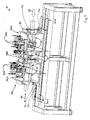
- the number 1 indicates a machine for cutting a tube extruded in continuous fashion into segments of a lesser and predetermined length.
- said machine 1 houses the tube generated by a continuous extruder positioned upstream (the extruder is not shown).
- tube means generically the set both of the cut segments, still operatively fastened to the machine 1, and of the part of tube not yet cut into segments.
- the machine 1 comprises a guide 30 that develops between a stroke-start 301 and a stroke end 302.
- the cutting machine 1 also comprises sliding means 3 that are movable along the guide 30 parallel to a direction 20 of advance of the tube along which the tube is to proceed according to a first sense of advance 21 oriented from the stroke-start 301 to the stroke end 302 of the guide 30.
- the tube moves along said first sense of advance 21 with its own velocity; said velocity is generally imposed by a suitable driving device (not shown) interposed between the cutting machine 1 and the extruder upstream.
- the machine 1 further comprises means 33 for actuating said sliding means 3 along said guide 30. Said sliding means 3, under the action of the actuating means 33, move both forward and backward along the guide 30.
- the actuating means 33 comprise a motion transmission 34 comprising a belt integral with a portion of the sliding means 3, closed in a loop on itself and wound around a pair of pulleys. Said motion transmission 34 is responsible for the reciprocating translation of the sliding means 3 along the guide 30.
- the actuating means 33 comprise a fluid-dynamic jack that actuates the sliding means 3.
- the sliding means 3 comprise a first station 31 for cutting the tube, said first cutting station 31 comprising a first shearing cutter 311 defining a first cutting plane 310 transverse to the direction 20 of advance of the tube.
- the first cutting plane 310 is orthogonal to the direction 20 of advance of the tube.
- the sliding means 3 further comprise a second station 32 for cutting the tube positioned upstream of the first cutting station 31 with respect to the first sense 21 of advance of the tube along the direction 20 of advance, said second cutting station 32 comprising a second shearing cutter 312 distanced from the first shearing cutter 311 and defining a second cutting plane 320 that is transverse to the direction 20 of advance of the tube.
- the first and the second shearing cutter 311, 312 are mutually distinct and separate.
- the second cutting plane 320 is orthogonal relative to the direction 20 of advance of the tube.
- the first and the second cutting plane 310, 320 are mutually parallel.
- the cutting action of the first and of the second shearing cutter 311, 312 can take place at least partly simultaneously, but it preferably takes place wholly simultaneously.
- shearing cutter means the portion of the corresponding cutting station which interacts physically with the tube, determining its split into two distinct, independent portions.
- This chamfer is advantageously used to facilitate the connection by insertion of two distinct segments whereof at least one has a bellmouth end.
- both the first and the second shearing cutter 311, 312 are constituted by a tool that can be a blade (see figure 7 ) or a rotating disk (see figure 8 ).
- To the shearing cutter can also be associated the portion 313 of the cutting station necessary to execute a conical chamfer.
- the sliding means 3 comprise means 50 for gripping tube portions, said gripping means 50 being positioned, relative to the first sense of advance 21 of the tube, at least upstream of the first cutting plane 310, downstream of the second cutting plane 320 and between the first and the second cutting plane 310, 320.
- the gripping means 50 are movable between a first configuration in which they securely grip corresponding tube portions and a second configuration in which they release said tube portions.
- the cutting machine 1 further comprises means for controlling the actuating means 33 and means for measuring the relative displacement between said tube and said first and second cutting plane 310, 320 along the direction of advance 20 of the tube.
- the actuating means 33 are able to synchronise with the motion of the tube the motion of each cutting station 31, 32 along the direction of advance 20, positioning the first and the second cutting plane 310, 320 at desired positions on the tube.
- the control means command the means 33 for actuating said sliding means 3 at least as a function:
- said gripping means 50 assume said first configuration to keep in position tube segments positioned at the first and at the second cutting plane 310, 320. Said second configuration is assumed after each cut to allow the relative motion of the tube and of the sliding means 3 along the direction 20 of advance of the tube.
- the relative displacement of the cutting stations 31, 32 with respect to the tube is possible.
- the action of the gripping means enables to maximise the cutting precision preventing undesired displacements between the tube and the first and/or the second shearing cutter 311,312.
- the sliding means 3 could also comprise more than two cutting stations 31, 32.
- each cutting station should be associated a corresponding cutting plane.
- shear scraps means the portion of the tube that is removed by the shearing cutter and that does not remain attached to either of the two segments generated by the cut.
- Figure 7 shows a cut without production of scraps
- figure 8 shows a cut with the production of a shear scrap by the second shearing cutter 312.
- the machine 1 comprises means for positioning the first and the second cutting plane 310, 320 at a mutual distance defined by the following formula: n ⁇ L + K where:
- the natural number n takes into account the fact that from the tube portion interposed between the first and the second cutting plane 310, 320 and obtained from the cut executed simultaneously by the first and by the second shearing cutter 311, 312, a number of segments of equal length L equal to the natural number n will be obtained.
- the value of the natural number n is greater than 1.
- the first corrective coefficient K is advantageously equal to 0.
- the thickness of the first and of the second shearing cutter 311, 312 is variable from 0 to 3 mm.
- each shearing cutter 311, 312 are associated multiple shearing planes included in an interval defined by the length of the scrap generated by the corresponding shearing cutter 311, 312 along the direction 20 of advance of the tube.
- the first and the second cutting plane 310, 320 coinciding with the two shearing planes mutually closest and generated at least in part simultaneously one by the first shearing cutter 311 and one by the second shearing cutter 312.
- the cutting planes 310, 320 are defined and as a function of the subsequent steps provided by the method implemented by the machine 1, in the formula n.L+K (previously indicated), if one wants to take into account the scrap generated by the shearing cutters 311, 312, it will be necessary to take into account only the scrap generated by the first shearing cutter 311.
- the first corrective coefficient is equal to the length of the scrap generated by the first shearing cutter 311 along the direction 20 of advance multiplied by n-1 where n is the aforesaid natural number. From this it is evident that if n is equal to 1, the first corrective coefficient K is nil.
- the cutting machine 1 further comprises a user interface to set the value of the preferential length L of the desired tube segments outputted by the machine 1.
- the preferential length L is the target length which the machine 1 is to produce.
- a number of segments of a length equal to said preferential length is usually alternated by the generation of a segment of greater dimensions. This depends both on the fact that the guide 30 has a finite development and on the operating procedures of the cutting machine 1 (as better explained below).
- the length of said segment of greater dimension can also be pre-set (e.g. to create a stock of segments of this length). These long segments are in any case usually generated in a smaller number than the segments of preferential length L and their generation constitutes a way to try to optimise the production of the machine 1.
- the machine 1 further comprises an electronic unit that enables to determine the value of the natural number n as a function of the value of the length L of the desired segments and of pre-set geometric parameters of the machine 1.
- the value of n should be the smallest possible, taking into account the maximum and minimum mutual distance whereat it is possible to position the first and the second cutting plane 310, 320. This is linked to the need to contain the length of the stroke which the sliding means 3 must have available.
- the maximum and minimum mutual distance whereat it is possible to position the first and the second cutting plane 310, 320 is a function of the constructive geometric parameters of the machine 1 and they are values that characterise a machine 1 and hence are known beforehand.
- the actuating means 33 comprise means 330 for regulating the mutual distance of the first and of the second cutting plane 310, 320.
- the regulating means 330 enable to change the distance between the first and the second cutting plane 310, 320 and consequently they can change the length of the desired tube segments outputted by the machine 1.
- the machine 1 comprises a remote centre for controlling the regulating means 330 which enables to activate the regulating means 330 without stopping the machine 1.
- the sliding means 3 comprise a carriage 36 comprising a first and a second portion 361, 362 that are mutually movable by the regulating means 330.
- the regulating means 330 are physically interposed between the first and the second portion 361, 362 of the carriage.
- the regulating means 330 thus also enable the physical connection between the first portion 361 and the second portion 362 of the carriage 36.
- the regulating means 330 comprise electromechanical systems or fluid-dynamic jacks.
- the measuring means comprise a position transducer 35 that measures the relative displacement of the first and of the second cutting station 31, 32.
- the sliding means 3 comprise:
- both the first and the second cutting station 31, 32 comprise: a drum 37 rotatable around a horizontal axis, first motorisation means 371a of the drum 37, means 372 for calibrating the cutting tools (see, for example, figure 3 ).
- the horizontal axis of rotation of the drum is coaxial with the longitudinal axis of development of the tube parallel to the direction 20 of advance.
- both the first and the second cutting station 31, 32 comprise second motorisation means 371b for actuating the cutting tools that enable the tool to rotate around its own axis of rotation.
- the drum 37 is defined by two planar flanges 373, with annular shape, mutually parallel which are rigidly interconnected by interposed spacers.
- the drum 37 is axially traversed for its entire length by a cavity 374 able to be travelled by the tube longitudinally and coaxially with the axis of rotation of the drum 37.
- the shearing cutter is supported by the drum 37 in such a way as to project in the cavity 374, transversely to the axis of rotation of the drum 37.
- the first and the second motorisation means 371a, 371b include motor members which are positioned externally to the rotatable drum 37 and are supported in stationary fashion by the sliding means 3. This enables to reduce the inertia of the rotating drum and make the cutting operations more rapid.
- the first motorisation means 371a include a motion transmission 375a which is operatively interposed between the motor member and the drum 37.
- the second motorisation means 371b include a motion transmission 375b which is operatively interposed between the motor member and the rotatable cutting tools.
- a similar configuration is known and described in the Italian patent application for industrial invention No. RN2003A000014 .
- the gripping means 50 comprise vices 51 which in the first configuration are tightened on the tube.
- Each vice 51 comprises at least one lower portion 511 and one upper portion 512 movable relative to each other, in the first configuration of the gripping means both the lower portion 511 and the upper portion 512 being tightened on the tube; in the second configuration of the gripping means 50 the upper portion 512 being moved away from the tube to allow the mutual sliding of the tube relative to the vice 51.
- the lower portions 511 of the vices 51 support at least part of the segments of the cut tube.
- the vices 51 are aligned and define the direction 20 of advance.
- the surfaces of the vices 51 destined to come in contact with the tube define a channel for sliding. Said channel is interrupted between a vice and the other and it is advantageously coaxial to the tube.
- the first cutting plane 310 there is a first pair of vices 51 astride the second cutting plane 320 there is a second pair of vices 51, said second pair of vices 51 being distinct from the first pair of vices 51.
- the first pair of vices is integral with the first cutting station 31, the second pair of vices is integral with the second cutting station 32.
- first and the second cutting plane 310, 320 there are two vices 51, one integral with the first cutting station 31 and one integral to the second cutting station 32.
- At least one of said two vices 51 interposed between the first and the second cutting plane 310, 320 comprises teeth 52 both complementarily shaped and opposite relative to recesses 53 obtained on the other vice 51; the insertion or extraction of the teeth 52 from the corresponding recesses 53 (see figures 4, 5, 6 ) allowing the at least partial co-penetration of one vice 51 in the other to compensate for the motion towards or away from each other of the first and of the second cutting station 31, 32 along the direction 20 of advance.
- the motion of the first and of the second cutting station 31, 32 toward or away from each other causes the first and the second cutting plane 310, 320 to move toward or away from each other.
- the presence of said teeth 52 and of the respective recesses 53 enables to approach the first cutting plane 310 to the second cutting plane 320 as far as possible and simultaneously enables the lower portion 511 of the vices 51 to support the tube segments even when the two vices 51 integral to the cutting stations 31, 32 are in a configuration of maximum mutual distancing.
- One of said two vices 51 interposed between the first and the second cutting plane 310, 320 is a part of the first pair of vices, the other is a part of the second pair of vices.
- the present invention further relates to a method for cutting a continuously extruded tube into segments of lesser and predetermined length by means of a cutting machine.
- Said method comprises the step of positioning the tube in a work area of the cutting machine 1.
- the tube is positioned placing its own axis of longitudinal development parallel to said guide 30 of the cutting machine 1.
- the method also comprises the step of making the tube advance along the direction 20 of advance according to the sense 21 of advance.
- the direction 20 of advance is advantageously parallel to the direction of development of the guide 30.
- the method further comprises the step of positioning the first and the second cutting plane 310, 320 at a mutual distance equal to: n ⁇ L + K where:
- the method further comprises synchronising to the motion of the tube the motion of the first and of the second cutting plane 310, 320 along the direction 20 of advance.
- a first and a second cut of the tube is executed at the first and the second cutting plane 310, 320.
- said cutting operation is executed wholly simultaneously by the first and by the second cutter 311, 312.
- each iterative cycle of said first procedure comprises the three following steps:
- the first procedure thus comprises a number of iterative cycles equal to the natural number n minus one unit.
- the second corrective coefficient Y is nil. If the scrap generated by the second shearing cutter 312 is neglected, then the third corrective coefficient X is nil.
- the value of the second corrective coefficient Y is equal to the length of the scrap generated by the first shearing cutter 311 and measured along the direction 20 of advance of the tube.
- the value of the third corrective coefficient X is equal to the length of the scrap generated by the second shearing cutter 312 and measured along the direction 20 of advance of the tube.
- the second and the third corrective coefficient Y, X assume the same value. Normally, in such cases the first and the second shearing cutters 311, 312 are identical (preferred solution).
- the method comprises a second iterative procedure that is activated if the progressive reference index i is greater than 1 and assumes a value equal to the natural number n and if the sliding means 3 are at a distance greater than a predetermined distance from the stroke-end 302 of the guide 30 or if the natural number n is unitary and the sliding means 3 are at a distance greater than a predetermined distance from the stroke-end 302 of the guide 30; said predetermined distance depends on the operating parameters of the machine 1, e.g. on the preferential length L of the segments, on the value of the natural number n, on the velocity of advance of the tube, etc..
- Said second iterative procedure is interrupted when, at the end of an iterative cycle, the sliding means 3 are at a lesser distance than the predetermined distance from the stroke-end 302 of the guide 30; every operating cycle of said second procedure comprises the following steps:
- the first and the second and the third and the fourth and the fifth corrective coefficient assume two alternative sets of values; a first set of values in which the first, as well as the second, as well as the third, as well as the fourth, as well as the fifth corrective coefficient are nil, in this case neglecting the scrap of the tube generated by the first and by the second shearing cutters 311,312.
- the sliding means 3 when the progressive reference index i assumes the value of the natural number n, they will return to the stroke-start 301 of the guide 30.
- a segment Following a cutting action by the first shearing cutter 311, downstream of said first shearing cutter 311 a segment will be generated having greater length than the preferential length L of the desired segments outputted by the machine and the method does not provide for said long segment to be further worked on by the machine 1.
- said long segment is not discarded, as it can still be used in applications where a longer tube is required.
- said long segment has a length whose value is pre-set and of interest (e.g. to increase stocks of tubes of a certain length).
- the first iterative procedure if the progressive reference index i is smaller than the natural number n, provides for the step of moving the first and the second cutting plane 310, 320 from the initial positions to the new positions, comprises the step of mutually approaching (advantageously, by the regulating means 330) the second cutting plane 320 and the first cutting plane 310 by a quantity equal to the second corrective coefficient Y. Neglecting the scrap generated by the second shearing cutter 312, based on the above description, the approach of the first and of the second cutting plane 310, 320 becomes nil as well.
- the approach enables to compensate for the fact that in the immediately preceding cut the second shearing cutter 312 removed a scrap from the tube along the direction 20 of advance (normally equal to the value of the thickness of the second shearing cutter 312).
- the control means govern the motion of the sliding means 3 taking into account the time required for the two edges to come in contact; said time is equal to the length of the scrap measured along the direction 20 of advance of the tube in relation to the velocity of advance of the tube.
- the method comprises the step of bringing back (advantageously by the regulating means 330) the distance between the first and the second cutting plane 310, 320 to the distance given by the formula n ⁇ L + K where:
- the method further comprises the step of setting the value L of the preferential length of the desired tube segments outputted by the machine 1, measured along the direction of advance of the tube. Said step is usually conducted before starting the cutting operations and it is important to determine the mutual distance whereat the first and the second cutting planes 310, 320 are to be set.
- the method provides in any case for the possibility of regulating the mutual distance of the first and of the second cutting plane 310, 320, this being possible also during the normal operation of the cutting machine 1 which will thus comply with the new instructions.
- the method provides for choosing the minimum value of "n" that enables to obtain the value expressed by the following relationship: n ⁇ L + K between a minimum and a maximum pre-set value.
- the geometric configuration of the machine 1 enables a regulation of the distance between the first and the second cutting plane 310, 320 from a minimum distance of 500 mm to a maximum distance of 700 mm.
- the sliding means 3 are at the stroke-start 301 of the guide 30. In this position, the sliding means 3 wait for an adequate segment of tube to slide, then they start translating along the tube and as soon as they reach a velocity near the velocity of the tube and as soon as they position the first cutting plane 310 at a distance from the end of the tube equal to the preferential length L, the vices 51 are closed and the cutting operation is executed (see figure 9 ).
- a first segment of length equal to the preferential length L and a second segment of length equal to three times the preferential length L are obtained.
- the vices 51 are opened and the sliding means 3 start to return towards the stroke-start 301 of the guide 30.
- the tube continues to slide in opposite direction and the relative displacements are detected between the tube and the first and the second cutting plane 310, 320 (given by the sum of the absolute displacements of the cutting planes 310, 320 and of the tube). Subsequently, the sliding means 3 stop and resume the motion in the opposite direction.
- the first cutting plane 310 is positioned upstream (relative to the first sense of advance 21 of the tube) and at a distance from the end of the as-yet uncut tube portion equal to the preferential length L.
- a cutting operation is executed, again obtaining a segment with length L equal to the preferential length and a segment whose length is equal to three times the preferential length.
- the operations described above are repeated, to cut the long segment just generated into segments having preferential length L and so on.
- the sliding means 3 At the end of one of the work cycles described above, if the sliding means 3 have no more travel available because they are too close to the stroke-end 302 of the guide 30, they can return in proximity to the stroke-start position 301.
- a subsequent cutting operation downstream of the first cutting plane 310 a segment is generated with a length that is usually pre-set before starting the machining (not necessarily multiple of the desired preferential length L), whilst between the first and the second cutting plane 310, 320 a segment is generated that is equal to or multiple of the desired preferential length L; then, the execution of the various cutting cycles as described previously is resumed.
- the dashed lines orthogonal to the tube represent the areas that will be cut from the cutting planes in the subsequent steps.
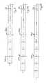
- Figures 12 through 14 show the same steps shown in figures 9 through 11 , if the scrap generated by the first and/or by the second cutter 311, 312 is not neglected.
- the scrap generated by the corresponding cutter is shown as a thick line, orthogonal to the tube.
- the invention achieves important advantages.
- Another important advantage is that it allows relatively small dimensions of the machine.
Abstract
Description
- The present invention relates to a method for cutting an extruded tube into segments of lesser and predetermined length.
- In drainage pipeline systems within buildings, plastic tubes are widely used, in particular made of PVC-U (rigid polyvinyl chloride), PP (polypropylene) and PE (polyethylene). In these systems, referring to the metric dimensions, the outer tube diameters employed rarely exceed 200 mm, whilst the smallest diameter used is normally 32 mm. The commercial lengths of the tubes are short relative to the tubes used in sewers or in pressurised fluid distribution pipelines, because the structure of the building is poorly suited to the installation of tubes longer than 3 metres. Commonly employed lengths, normally available on the market, are: 150mm, 250mm, 500mm, 750mm, 1000mm, 1500mm, 2000mm and 3000mm. The most widely used technique for joining tubes is the bellmouth with a sealing elastomeric gasket: the end of the tube is widened and provided with a seat for a gasket, in order to enable the insertion of another tube into the end, achieving a junction with fluid-dynamic tightness.
- The end of the tube that is inserted into the bellmouth is chamfered, so insertion into the bellmouth is facilitated and the risks of damaging the gasket are reduced. The nominal commercial length of the tube with bellmouth does not consider the bellmouth portion, because the length of the bellmouth is irrelevant in calculating the extension of the pipeline. Tubes with bellmouths at both ends also have considerable commercial success.
- Plastic tube production lines are extrusion lines with continuous production in which the extruded tube advances along the line at uniform velocity (extrusion velocity). In the line is normally present an automatic cutting machine, commanded by an electronic control unit, able to obtain tube segments with chamfered end. The length of the cut segments corresponds to the nominal commercial length plus a segment with sufficient length to obtain, with subsequent bellmouth making machine, with thermoforming process, the bellmouth. In draining tubes within buildings, the products most on demand are short tubes, usually tubes having commercial length of up to 500 mm.
- The traditional automatic cutting machine is configured as a carriage that moves within a frame along the axis of the tube. Within the carriage is located a drum comprising two rings, separated by spacers, within which is obtained a cavity that is coaxial to the tube. In the drum is located the cutting tool. The drum is able to rotate at high velocity around the tube. Since the tube is in constant rectilinear motion, when the cut is performed the carriage must also move at the same velocity as the tube. At the time the cut is executed, two clamps positioned on the carriage at the side of the cutting assembly, close on the tube, achieving a rigid carriage-tube structure that moves at the same velocity, thereby allowing maximum cutting precision. The electronic control unit receives the signal that commands the execution of the cutting cycles from an electronic position measurer that, through an electro-mechanical transducer (wheel-encoder), constantly measures the velocity of the tube and the required lengths of tube to be cut.
- When the cut is commanded, the carriage starts from a motionless condition and from a starting position, follows and reaches the point to be cut, synchronises to the velocity of the tube, closes the clamps and through the cutting tool performs the cutting cycle. Once the cut is completed, the clamps release the tube and the carriage returns to the starting position, awaiting another cutting command. It is evident that the higher the extrusion velocity, the greater will be the length of travel needed by the carriage to complete the work cycle. It is also evident that, for equal extrusion velocity, the shorter the lengths of tube required, the greater will be the number of cuts the machine must execute in a unit of time. To limit the length of the working stroke of the carriage and increase, for equal stroke available, the number of producible short segments, the so-called "flying" cut technique described in the patent
EP 0129515 is advantageous. This technique enables to achieve working cycles characterised by sequences of short segments alternating to a long segment. With the "flying cut" control technique, the carriage provided with a shearing cutter does not take as a reference the absolute stroke-start position, but the relative position on the tube where the next cut is to be executed with respect to the instantaneous position of the carriage. By so doing, after the first cut, the carriage in the return stroke does not return to a stroke-start position, but when it arrives in the vicinity of the position of the tube where the next cut is to be executed, it stops "on the fly", it reverses its motion and it reaches the cutting point, it synchronises the velocity with the extrusion velocity and it carries out the cutting cycle, and so on until the end of the working stroke. After completing the working stroke, the carriage returns to the stroke-start position and from said position it can cut a long segment and then resume the sequence of cuts "on the fly" that produce the short segments. - The technical evolution of the extrusion lines is characterised by a constant increase of the extrusion velocity, whilst the application of drainage tubes in buildings requires prevalently short segments with bellmouths. To meet this requirement, no relevant problems are associated with installing at the end of the extrusion line multiple bellmouth-making machines, able to sustain the arrival in a given time of an ever greater number of tubes to be shaped with bellmouth ends. However, it is necessary to increase ever more the velocity with which the tube segments are produced in order to keep pace with the velocity of extrusion of the tubes.
- Document
US A 5 224 368 illustrates a flying die apparatus having multiple heads for performing various operations (for example: cutting and/or shearing) on tube stock or other shaped stock exiting a forming machine. - The following features are known from
US A 5 224 368 . - A method for cutting a continuously extruded tube into segments of lesser and predetermined length by means of a cutting machine, the cutting machine comprising:
- a guide that develops between a stroke-start and a stroke-end;
- sliding means that are movable along the guide parallel to a direction of advance of the tube along which the tube is to proceed according to a first sense of advance oriented from the stroke-start to the stroke end of the guide;
- means for actuating said sliding means along the guide;
- a second station for cutting the tube positioned upstream of the first cutting station with respect to the first sense of advance of the tube along the direction of advance, said second cutting station comprising a second shearing cutter distanced from the first shearing cutter and defining a second cutting plane that is transverse to the direction of advance of the tube;
- means for gripping tube portions, said gripping means being positioned between the first and the second cutting plane; said gripping means being movable between a first configuration in which they securely grip corresponding tube portions and a second configuration in which they release said tube portions;
- positioning the tube in a work area of the cutting machine;
- making the tube advance along the direction of advance according to the first sense of advance;
- positioning the first and the second cutting plane at a mutual distance:
- synchronising to the motion of the tube the motion of the first and of the second cutting plane along the direction of advance;
- executing by means of the first and of the second cutter, a first and a second cut of the tube at the first and the second cutting plane.
- An object of the present invention is to overcome the drawbacks described above, making available a method for cutting an extruded tube into segments with a lesser and predetermined length which enables to obtain a high machining rate.
- Another object of the present invention is to make available a method for cutting an extruded tube into segments with a lesser and predetermined length which enables to obtain relatively small bulks.
- These objects and others beside, which shall become more readily apparent in the description that follows, are achieved, in accordance with the present invention, by a method for cutting an extruded tube into segments of lesser and predetermined length having structural and functional characteristics in accordance with the appended independent claims, additional embodiments thereof being identified in the appended and corresponding dependent claims.
- The invention is described in greater detail hereafter with the aid of the drawings, which represent an embodiment provided purely by way of non limiting example.
-
Figure 1 shows a perspective view of a machine suitable for executing the present invention. -
Figure 2 shows a schematic view of a portion of the machine suitable for executing the present invention. -
Figure 3 shows a portion of the machine suitable for executing the present invention shown infigure 1 . -
Figures 4, 5, 6 show distinct configurations of a detail of the machine suitable for executing the present invention. -
Figures 7, 8 , show two distinct constructive solutions of a detail of a machine according to the present invention. -
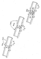
Figures 9, 10, 11 show some sequences of the machining of the tube. -
Figures 12, 13, 14 show some sequences of the machining of the tube if the shearing scraps are not neglected. - With reference to
Figure 1 , the number 1 indicates a machine for cutting a tube extruded in continuous fashion into segments of a lesser and predetermined length. Advantageously, said machine 1 houses the tube generated by a continuous extruder positioned upstream (the extruder is not shown). - In the present description, the term "tube" means generically the set both of the cut segments, still operatively fastened to the machine 1, and of the part of tube not yet cut into segments.
- The machine 1 comprises a
guide 30 that develops between a stroke-start 301 and astroke end 302. The cutting machine 1 also comprises sliding means 3 that are movable along theguide 30 parallel to adirection 20 of advance of the tube along which the tube is to proceed according to a first sense ofadvance 21 oriented from the stroke-start 301 to thestroke end 302 of theguide 30. The tube moves along said first sense ofadvance 21 with its own velocity; said velocity is generally imposed by a suitable driving device (not shown) interposed between the cutting machine 1 and the extruder upstream. The machine 1 further comprises means 33 for actuating said sliding means 3 along saidguide 30. Said sliding means 3, under the action of the actuating means 33, move both forward and backward along theguide 30. As schematically shown infigure 2 , the actuating means 33 comprise amotion transmission 34 comprising a belt integral with a portion of the sliding means 3, closed in a loop on itself and wound around a pair of pulleys. Saidmotion transmission 34 is responsible for the reciprocating translation of the sliding means 3 along theguide 30. - Alternatively (solution not shown herein), the actuating means 33 comprise a fluid-dynamic jack that actuates the sliding means 3.
- The sliding means 3 comprise a
first station 31 for cutting the tube, said first cuttingstation 31 comprising afirst shearing cutter 311 defining afirst cutting plane 310 transverse to thedirection 20 of advance of the tube. Advantageously, thefirst cutting plane 310 is orthogonal to thedirection 20 of advance of the tube. - The sliding means 3 further comprise a
second station 32 for cutting the tube positioned upstream of the first cuttingstation 31 with respect to thefirst sense 21 of advance of the tube along thedirection 20 of advance, said second cuttingstation 32 comprising asecond shearing cutter 312 distanced from thefirst shearing cutter 311 and defining asecond cutting plane 320 that is transverse to thedirection 20 of advance of the tube. - The first and the
second shearing cutter - Advantageously, the
second cutting plane 320 is orthogonal relative to thedirection 20 of advance of the tube. - Advantageously, the first and the
second cutting plane - The cutting action of the first and of the
second shearing cutter - The term "shearing cutter" means the portion of the corresponding cutting station which interacts physically with the tube, determining its split into two distinct, independent portions. A
portion 313 of the cutting station that executes a simple chamfer, but does not split the tube into two parts, is not a part of the shearing cutter. See in this regardfigure 8 . This chamfer is advantageously used to facilitate the connection by insertion of two distinct segments whereof at least one has a bellmouth end. Advantageously, both the first and thesecond shearing cutter figure 7 ) or a rotating disk (seefigure 8 ). To the shearing cutter can also be associated theportion 313 of the cutting station necessary to execute a conical chamfer. - The sliding means 3 comprise means 50 for gripping tube portions, said gripping
means 50 being positioned, relative to the first sense ofadvance 21 of the tube, at least upstream of thefirst cutting plane 310, downstream of thesecond cutting plane 320 and between the first and thesecond cutting plane - The cutting machine 1 further comprises means for controlling the actuating means 33 and means for measuring the relative displacement between said tube and said first and
second cutting plane advance 20 of the tube. Before every cut and on the command of the control means, the actuating means 33 are able to synchronise with the motion of the tube the motion of each cuttingstation advance 20, positioning the first and thesecond cutting plane means 33 for actuating said sliding means 3 at least as a function: - of the information provided by said measuring means;
- of the desired length of the tube segments to be produced with the machine 1.
- Once the synchronisation is completed, before each cut, said gripping
means 50 assume said first configuration to keep in position tube segments positioned at the first and at thesecond cutting plane direction 20 of advance of the tube. - In said second configuration, therefore, the relative displacement of the cutting
stations - The sliding means 3 could also comprise more than two cutting
stations stations - In the machining of polypropylene and polyethylene tubes for drains to be used within buildings, the cutting operation usually takes place without production of shear scraps. On the contrary, the cutting operation on rigid polyvinyl chloride tubes usually takes place with production of shear scraps. The term "shear scraps" means the portion of the tube that is removed by the shearing cutter and that does not remain attached to either of the two segments generated by the cut.
-
Figure 7 shows a cut without production of scraps, whilstfigure 8 shows a cut with the production of a shear scrap by thesecond shearing cutter 312. - The machine 1 comprises means for positioning the first and the
second cutting plane 
- n: is a natural number greater than 0;
- L: is a preferential length of the desired tube segments outputted by the machine, measured along the direction of
advance 20 of the tube; - K: is a first corrective coefficient to take into account the length, measured along the direction of advance of the tube, of a scrap generated by the first and/or by the
second shearing cutter direction 20 of advance of the tube. - The natural number n takes into account the fact that from the tube portion interposed between the first and the
second cutting plane second shearing cutter - If one considers negligible the scrap generated by the first and by the
second shearing cutter second shearing cutter - If one does not consider negligible the scrap generated by the first and by the
second shearing cutter shearing cutter shearing cutter direction 20 of advance of the tube. The first and thesecond cutting plane first shearing cutter 311 and one by thesecond shearing cutter 312. - Constant reference shall be made hereafter to this definition of the cutting
planes direction 20 of advance. By virtue of the way the cuttingplanes shearing cutters first shearing cutter 311. In this case, the first corrective coefficient is equal to the length of the scrap generated by thefirst shearing cutter 311 along thedirection 20 of advance multiplied by n-1 where n is the aforesaid natural number. From this it is evident that if n is equal to 1, the first corrective coefficient K is nil. - The cutting machine 1 further comprises a user interface to set the value of the preferential length L of the desired tube segments outputted by the machine 1. The preferential length L is the target length which the machine 1 is to produce. A number of segments of a length equal to said preferential length is usually alternated by the generation of a segment of greater dimensions. This depends both on the fact that the
guide 30 has a finite development and on the operating procedures of the cutting machine 1 (as better explained below). Advantageously, the length of said segment of greater dimension can also be pre-set (e.g. to create a stock of segments of this length). These long segments are in any case usually generated in a smaller number than the segments of preferential length L and their generation constitutes a way to try to optimise the production of the machine 1. - The machine 1 further comprises an electronic unit that enables to determine the value of the natural number n as a function of the value of the length L of the desired segments and of pre-set geometric parameters of the machine 1. In particular, the value of n should be the smallest possible, taking into account the maximum and minimum mutual distance whereat it is possible to position the first and the
second cutting plane second cutting plane - Advantageously, the actuating means 33 comprise means 330 for regulating the mutual distance of the first and of the
second cutting plane second cutting plane - Advantageously, the machine 1 comprises a remote centre for controlling the regulating means 330 which enables to activate the regulating means 330 without stopping the machine 1.
- As exemplified in
figure 1 , the sliding means 3 comprise acarriage 36 comprising a first and asecond portion first portion 361 of thecarriage 36 is obtained the first cuttingstation 31, on thesecond portion 362 of the carriage is obtained thesecond cutting station 32. Advantageously, the regulating means 330 are physically interposed between the first and thesecond portion first portion 361 and thesecond portion 362 of thecarriage 36. Usually, the regulating means 330 comprise electromechanical systems or fluid-dynamic jacks. Advantageously, the measuring means comprise aposition transducer 35 that measures the relative displacement of the first and of thesecond cutting station - By intervening on the regulating means 330, it is thus possible to move mutually closer or farther away the first and the
second portion carriage 36 and hence the first and thesecond cutting station second cutting plane - In an alternative embodiment, the sliding means 3 comprise:
- a first carriage movable along said guiding means 30, on said carriage being obtained the first cutting
station 31; - a second carriage, movable parallel to the
direction 20 of advance of the tube, on said second carriage being obtained thesecond cutting station 32; - In general, both the first and the
second cutting station drum 37 rotatable around a horizontal axis, first motorisation means 371a of thedrum 37, means 372 for calibrating the cutting tools (see, for example,figure 3 ). The horizontal axis of rotation of the drum is coaxial with the longitudinal axis of development of the tube parallel to thedirection 20 of advance. Advantageously, if the cutting tool is rotatable around its own axis, both the first and thesecond cutting station - The
drum 37 is defined by twoplanar flanges 373, with annular shape, mutually parallel which are rigidly interconnected by interposed spacers. Thedrum 37 is axially traversed for its entire length by acavity 374 able to be travelled by the tube longitudinally and coaxially with the axis of rotation of thedrum 37. The shearing cutter is supported by thedrum 37 in such a way as to project in thecavity 374, transversely to the axis of rotation of thedrum 37. Advantageously, two cutting tools are present, on diametrically opposite positions relative to the axis of rotation of thedrum 37 in order to be able to operate simultaneously on opposite circumference arcs of the tube and enable the cutting of the tube by means of a single rotation of thedrum 37 around its axis of rotation. As exemplified infigure 3 , the first and the second motorisation means 371a, 371b include motor members which are positioned externally to therotatable drum 37 and are supported in stationary fashion by the sliding means 3. This enables to reduce the inertia of the rotating drum and make the cutting operations more rapid. In particular, the first motorisation means 371a include a motion transmission 375a which is operatively interposed between the motor member and thedrum 37. The second motorisation means 371b include a motion transmission 375b which is operatively interposed between the motor member and the rotatable cutting tools. A similar configuration is known and described in the Italian patent application for industrial invention No.RN2003A000014 - The gripping means 50 comprise
vices 51 which in the first configuration are tightened on the tube. - Each
vice 51 comprises at least onelower portion 511 and oneupper portion 512 movable relative to each other, in the first configuration of the gripping means both thelower portion 511 and theupper portion 512 being tightened on the tube; in the second configuration of the gripping means 50 theupper portion 512 being moved away from the tube to allow the mutual sliding of the tube relative to thevice 51. - In particular, the
lower portions 511 of thevices 51 support at least part of the segments of the cut tube. Advantageously, thevices 51 are aligned and define thedirection 20 of advance. In particular, the surfaces of thevices 51 destined to come in contact with the tube define a channel for sliding. Said channel is interrupted between a vice and the other and it is advantageously coaxial to the tube. Astride thefirst cutting plane 310 there is a first pair ofvices 51, astride thesecond cutting plane 320 there is a second pair ofvices 51, said second pair ofvices 51 being distinct from the first pair ofvices 51. In particular, the first pair of vices is integral with the first cuttingstation 31, the second pair of vices is integral with thesecond cutting station 32. - Between the first and the
second cutting plane vices 51, one integral with the first cuttingstation 31 and one integral to thesecond cutting station 32. At least one of said twovices 51 interposed between the first and thesecond cutting plane teeth 52 both complementarily shaped and opposite relative torecesses 53 obtained on theother vice 51; the insertion or extraction of theteeth 52 from the corresponding recesses 53 (seefigures 4, 5, 6 ) allowing the at least partial co-penetration of onevice 51 in the other to compensate for the motion towards or away from each other of the first and of thesecond cutting station direction 20 of advance. The motion of the first and of thesecond cutting station second cutting plane teeth 52 and of therespective recesses 53 enables to approach thefirst cutting plane 310 to thesecond cutting plane 320 as far as possible and simultaneously enables thelower portion 511 of thevices 51 to support the tube segments even when the twovices 51 integral to the cuttingstations vices 51 interposed between the first and thesecond cutting plane - The present invention further relates to a method for cutting a continuously extruded tube into segments of lesser and predetermined length by means of a cutting machine.
- To said machine 1 and to its components, constant reference shall be made hereafter.
- Said method comprises the step of positioning the tube in a work area of the cutting machine 1. Advantageously, the tube is positioned placing its own axis of longitudinal development parallel to said
guide 30 of the cutting machine 1. The method also comprises the step of making the tube advance along thedirection 20 of advance according to thesense 21 of advance. Thedirection 20 of advance is advantageously parallel to the direction of development of theguide 30. - The method further comprises the step of positioning the first and the
second cutting plane 
- n: is a natural number greater than 0;
- L: is the preferential length of the desired tube segments outputted by the machine, measured along the direction of advance of the tube;
- K: is a first corrective coefficient that takes into account the length, measured along the direction of advance of the tube, of the scrap generated by the first and/or by the
second shearing cutter - The method further comprises synchronising to the motion of the tube the motion of the first and of the
second cutting plane direction 20 of advance. - Subsequently, at least in part simultaneously, by means of the first and of the
second cutter second cutting plane - Advantageously, said cutting operation is executed wholly simultaneously by the first and by the
second cutter - Advantageously, after executing the first and the second cut, if the natural number n is greater than 1, the implementation of a first iterative procedure is activated, each iteration whereof being identified by a progressive reference index i whose initial value is unitary. Said first procedure is interrupted when the progressive reference index i assumes a value equal to the natural number n; each iterative cycle of said first procedure comprises the three following steps:
- determining a displacement relative to the tube of the first and of the
second cutting plane first sense 21 of advance of the tube; in the initial positions and in the new positions, the displacement of the first and of thesecond cutting plane direction 20 of advance being synchronised to that of the tube; the displacement of thefirst cutting plane 310 is evaluated relative to a point integral with the portion of tube that in the initial position of thefirst cutting plane 310 is placed, relative to the first sense ofadvance 21 of the tube, immediately upstream of thefirst shearing cutter 311, said displacement of thefirst cutting plane 310 being provided by the following formula:
- L: is the preferential length of the desired tube segments outputted by the machine, measured along the direction of advance of the tube;
- Y: is a second corrective coefficient to take into account the length, measured along the direction of advance of the tube, of the scrap generated by the first and/or by the
second shearing cutter
second cutting plane 320 being evaluated relative to a point integral with the portion of tube that in the initial position of thesecond cutting plane 320 is placed, relative to the first sense ofadvance 21 of the tube, immediately upstream of thesecond shearing cutter 312, said displacement of thesecond cutting plane 320 being provided by the following formula:
- L: is the preferential length of the desired tube segments outputted by the machine, measured along the direction of advance of the tube;
- X is a third corrective coefficient to take into account the length, measured along the direction of advance of the tube, of the scrap generated by the first and/or by the
second shearing cutter
- cutting the tube in the new positions of the first and of the
second cutting plane second shearing cutter - increasing by one unit the value of the progressive reference index i.
- The first procedure thus comprises a number of iterative cycles equal to the natural number n minus one unit.
- If one neglects the scrap generated by the
first shearing cutter 311, then the second corrective coefficient Y is nil. If the scrap generated by thesecond shearing cutter 312 is neglected, then the third corrective coefficient X is nil. - In particular, the value of the second corrective coefficient Y is equal to the length of the scrap generated by the
first shearing cutter 311 and measured along thedirection 20 of advance of the tube. - The value of the third corrective coefficient X is equal to the length of the scrap generated by the
second shearing cutter 312 and measured along thedirection 20 of advance of the tube. - If the length of the scrap generated by the first and by the
second shearing cutter direction 20 of advance is identical, then the second and the third corrective coefficient Y, X assume the same value. Normally, in such cases the first and thesecond shearing cutters - Appropriately, the method comprises a second iterative procedure that is activated if the progressive reference index i is greater than 1 and assumes a value equal to the natural number n and if the sliding means 3 are at a distance greater than a predetermined distance from the stroke-
end 302 of theguide 30 or if the natural number n is unitary and the sliding means 3 are at a distance greater than a predetermined distance from the stroke-end 302 of theguide 30; said predetermined distance depends on the operating parameters of the machine 1, e.g. on the preferential length L of the segments, on the value of the natural number n, on the velocity of advance of the tube, etc.. Said second iterative procedure is interrupted when, at the end of an iterative cycle, the sliding means 3 are at a lesser distance than the predetermined distance from the stroke-end 302 of theguide 30; every operating cycle of said second procedure comprises the following steps: - determining a displacement relative to the tube of the first and of the
second cutting plane first sense 21 of advance of the tube; in the initial positions and in the new positions, the displacement of the first and of thesecond cutting plane direction 20 of advance being synchronised to that of the tube;
the displacements of the first and of thesecond cutting plane second cutting plane 320 is placed, relative to the first sense ofadvance 21 of the tube, immediately upstream of thesecond shearing cutter 312, the displacements of the first and of thesecond cutting plane 

- n: is the natural number greater than 0;
- L: is the preferential length of the desired tube segments outputted by the machine, measured along the direction of advance of the tube;
- H is a fourth corrective coefficient to take into account the length, measured along the direction of advance of the tube, of the scrap generated by the first and/or by the
second shearing cutter - Z: is a fifth corrective coefficient to take into account the length, measured along the direction of advance of the tube, of the scrap generated by the first and/or by the
second shearing cutter
- cutting the tube in the new positions of the first and of the
second cutting plane second shearing cutter - activating said first procedure again if the natural number n is greater than 1.
- If one neglects the scraps of the tube generated both by the first and by the
second shearing cutter - More in general, the value of the fourth and of the fifth corrective coefficient are given by the following relationships:


- n: is the natural number greater than 0;
- H is the fourth corrective coefficient to take into account the length, measured along the direction of advance of the tube, of the scrap generated by the first and/or by the
second shearing cutter - Z is the fifth corrective coefficient to take into account the length, measured along the direction of advance of the tube, of the scrap generated by the first and/or by the
second shearing cutter - S1 is the length of the scrap generated by the
first shearing cutter 311; - S2 is the length of the scrap generated by the
second shearing cutter 312. - Advantageously, the first and the second and the third and the fourth and the fifth corrective coefficient assume two alternative sets of values; a first set of values in which the first, as well as the second, as well as the third, as well as the fourth, as well as the fifth corrective coefficient are nil, in this case neglecting the scrap of the tube generated by the first and by the second shearing cutters 311,312.
- Alternatively, to take into account the scrap of the tube generated by the first and by the
second shearing cutter 


- n: is the natural number greater than 0;
- L: is the preferential length of the desired tube segments outputted by the machine, measured along the direction of
advance 20 of the tube; - K: is the first corrective coefficient to take into account the length, measured along the direction of advance of the tube, of the scrap generated by the first and/or by the
second shearing cutter - Y is the second corrective coefficient to take into account the length, measured along the direction of advance of the tube, of the scrap generated by the first and/or by the
second shearing cutter - X is the third corrective coefficient to take into account the length, measured along the direction of advance of the tube, of the scrap generated by the first and/or by the
second shearing cutter - H is the fourth corrective coefficient to take into account the length, measured along the direction of advance of the tube, of the scrap generated by the first and/or by the
second shearing cutter - Z is the fifth corrective coefficient to take into account the length, measured along the direction of advance of the tube, of the scrap generated by the first and/or by the
second shearing cutter - S1 is the length of the scrap generated by the
first shearing cutter 311; - S2 is the length of the scrap generated by the
second shearing cutter 312. - If the sliding means 3, when the progressive reference index i assumes the value of the natural number n, are at a lesser distance than said predetermined distance from the stroke-
end 302 of theguide 30, they will return to the stroke-start 301 of theguide 30. Following a cutting action by thefirst shearing cutter 311, downstream of said first shearing cutter 311 a segment will be generated having greater length than the preferential length L of the desired segments outputted by the machine and the method does not provide for said long segment to be further worked on by the machine 1. Anyway, said long segment is not discarded, as it can still be used in applications where a longer tube is required. In general, said long segment has a length whose value is pre-set and of interest (e.g. to increase stocks of tubes of a certain length). - The first iterative procedure, if the progressive reference index i is smaller than the natural number n, provides for the step of moving the first and the
second cutting plane second cutting plane 320 and thefirst cutting plane 310 by a quantity equal to the second corrective coefficient Y. Neglecting the scrap generated by thesecond shearing cutter 312, based on the above description, the approach of the first and of thesecond cutting plane - The approach enables to compensate for the fact that in the immediately preceding cut the
second shearing cutter 312 removed a scrap from the tube along thedirection 20 of advance (normally equal to the value of the thickness of the second shearing cutter 312). As a result of the advance of the tube portion outputted by the extruder, the two edges of the tube generated by the cutting action of thesecond shearing cutter 312 will very quickly come in contact and in the absence of the mutual approach of the two cuttingplanes direction 20 of advance of the tube in relation to the velocity of advance of the tube. - If the progressive reference index i assumes a value equal to the natural number n, the method comprises the step of bringing back (advantageously by the regulating means 330) the distance between the first and the
second cutting plane 
- n is the natural number greater than 0;
- L is the preferential length of the desired tube segments outputted by the machine, measured along the direction of advance of the tube;
- K is the first corrective coefficient to take into account the length, measured along the direction of advance of the tube, of the scrap generated by the first and/or by the
second shearing cutter - The method further comprises the step of setting the value L of the preferential length of the desired tube segments outputted by the machine 1, measured along the direction of advance of the tube. Said step is usually conducted before starting the cutting operations and it is important to determine the mutual distance whereat the first and the second cutting planes 310, 320 are to be set. The method provides in any case for the possibility of regulating the mutual distance of the first and of the
second cutting plane - Once the value L of the preferential length is chosen, the method provides for choosing the minimum value of "n" that enables to obtain the value expressed by the following relationship:

- With reference to
Figures 9 through 11 , an illustrative example of the invention is described below. - Suppose a polypropylene tube is to be machined, with diameter 110 mm and thickness 2.7 mm, and that bellmouth tubes are to be produced with preferential length L equal to 230 mm (including the part of tube, e.g. 80 mm long, whereon the bellmouth is to be formed). For the sake of simplicity, let it be assumed that the shearing cutter determines no cutting scrap.
- Let it be supposed that the geometric configuration of the machine 1 enables a regulation of the distance between the first and the
second cutting plane second cutting plane - Initially, the sliding means 3 are at the stroke-
start 301 of theguide 30. In this position, the sliding means 3 wait for an adequate segment of tube to slide, then they start translating along the tube and as soon as they reach a velocity near the velocity of the tube and as soon as they position thefirst cutting plane 310 at a distance from the end of the tube equal to the preferential length L, thevices 51 are closed and the cutting operation is executed (seefigure 9 ). - Using the two cutting
stations vices 51 are opened and the sliding means 3 start to return towards the stroke-start 301 of theguide 30. During this return phase, the tube continues to slide in opposite direction and the relative displacements are detected between the tube and the first and thesecond cutting plane 310, 320 (given by the sum of the absolute displacements of the cuttingplanes first cutting plane 310 is positioned at one third of the second segment previously generated (and maintaining unaltered the relative distance of the first and of thesecond cutting plane 310, 320), thevices 51 close and a cutting operation is executed (seefigure 10 ). With said cutting action, 2 additional segments with preferential length L are obtained as well as a third segment whose length is twice the preferential length L. Subsequently (in the manner described above) thefirst cutting plane 310 is moved relative to the tube in such a way as to position thefirst cutting plane 310 at half the third segment, previously generated. In this case, too, the relative distance of the first and of thesecond cutting plane second cutting station figure 11 ). The machine has thus executed a work cycle and with three cutting actions, 6 segments having length equal to the preferential length have been obtained. It is evident that the traditional machine configured with a single cutting plane would, in the same working time, have obtained a smaller number of segments. - Subsequently, the
first cutting plane 310 is positioned upstream (relative to the first sense ofadvance 21 of the tube) and at a distance from the end of the as-yet uncut tube portion equal to the preferential length L. A cutting operation is executed, again obtaining a segment with length L equal to the preferential length and a segment whose length is equal to three times the preferential length. Subsequently, the operations described above are repeated, to cut the long segment just generated into segments having preferential length L and so on. - At the end of one of the work cycles described above, if the sliding means 3 have no more travel available because they are too close to the stroke-
end 302 of theguide 30, they can return in proximity to the stroke-start position 301. With a subsequent cutting operation, downstream of the first cutting plane 310 a segment is generated with a length that is usually pre-set before starting the machining (not necessarily multiple of the desired preferential length L), whilst between the first and thesecond cutting plane 310, 320 a segment is generated that is equal to or multiple of the desired preferential length L; then, the execution of the various cutting cycles as described previously is resumed. Infigure 9 through 11 , the dashed lines orthogonal to the tube represent the areas that will be cut from the cutting planes in the subsequent steps. -
Figures 12 through 14 show the same steps shown infigures 9 through 11 , if the scrap generated by the first and/or by thesecond cutter - The invention achieves important advantages.
- First of all, it enables to obtain a high machining rate.
- Another important advantage is that it allows relatively small dimensions of the machine.
- The invention thus conceived can be subject to numerous modifications and variants, without thereby departing from the scope of the claims.
said sliding means further comprising:
the control means commanding said actuating means of said sliding means at least according to the information provided by said measuring means and to the desired length of the tube segments to be produced with the machine; once the synchronisation is completed, before each cut, said gripping means assume said first configuration to keep in position tube segments positioned at the first and at the second cutting plane, said second configuration being assumed after each cut to allow the relative motion of the tube and of the sliding means along the direction of advance of the tube;
the method comprising the steps of
Claims (23)
- A method for cutting a continuously extruded tube into segments of lesser and predetermined length by means of a cutting machine (1), the cutting machine (1) comprising:- a guide (30) that develops between a stroke-start (301) and a stroke-end (302);- sliding means (3) that ate movable along the guide (30) parallel to a direction (20) of advance of the tube along which the tube is to proceed according to a first sense of advance (21) oriented from the stroke-start (301) to the stroke end (302) of the guide (30);- means (33) for actuating said sliding means (3) along the guide (30);said sliding means (3) comprising a first station (31) for cutting the tube, said fist cutting station (31) comprising in turn a first shearing cutter (311) defining a first cutting plane (310) transverse to the direction (20) of advance;
said sliding means (3) further comprising:- a second station (32) for cutting the tube positioned upstream of the first cutting station (31) with respect to the first sense (21) of advance of the tube along the direction (20) of advance, said second cutting station (32) comprising a second shearing cutter (312) distanced from the first shearing cutter (311) and defining a second cutting plane (320) that is transverse to the direction (20) of advance of the tube;- means (50) for gripping tube portions, said gripping means (50) being positioned, relative to the first sense of advance (21) of the tube, upstream of the first cutting plane (310), downstream of the second cutting plane (320) and between the first and the second cutting plane (310, 320); said gripping means being movable between a first configuration in which they securely grip corresponding tube portions and a second configuration in which they release said tube portions;said cutting machine (1) further comprising means for controlling the actuating means (33) and means for measuring the relative displacement between said tube and said first and second cutting plane (310, 320) along the direction of advance (20); before every cut and on the command of the control means, the actuating means (33) being able to synchronise with the motion of the tube the motion of each cutting station (31, 32) along the direction of advance (20), positioning the first and the second cutting plane (310, 320) at desired positions on the tube;
the control means commanding said actuating means (33) of said sliding means (3) at least according to the information provided by said measuring means and to the desired length of the tube segments to be produced with the machine (1); once the synchronisation is completed, before each cut, said gripping means (50) assume said first configuration to keep in position tube segments positioned at the first and at the second cutting plane (310, 320), said second configuration being assumed after each cut to allow the relative motion of the tube and of the sliding means (3) along the direction (20) of advance of the tube;
the method comprising the steps of- positioning the tube in a work area of the cutting machine (1);- making the tube advance along the direction of advance (20) according to the first sense (21) of advance;- positioning the first and the second cutting plane (310, 320) at a mutual distance equal to:
where:n: is a natural number greater than 0;L: is a preferential length of the desired tube segments outputted by the machine, measured along the direction of advance of the tube;K: is a first corrective coefficient to take into account the length, measured along the direction of advance of the tube, of the scrap generated by the first and/or by the second shearing cutter (311, 312);- synchronising to the motion of the tube the motion of the first and of the second cutting plane (310, 320) along the direction (20) of advance;- executing at least in part simultaneously, by means of the first and of the second cutter (311, 312), a first and a second cut of the tube at the first and the second cutting plane (310, 320). - A method as claimed in claim 1, characterised in that after executing the first and the second cut, if the natural number n is greater than 1, the implementation of a first iterative procedure is activated, each iteration whereof being identified by a progressive reference index i whose initial value is unitary, said first procedure being interrupted when the progressive reference index i assumes a value equal to the natural number n; each iterative cycle of said first procedure comprising the steps of:- determining a displacement relative to the tube of the first and of the second cutting plane (310, 320) from initial positions to new positions located upstream of the corresponding initial positions relative to the first sense (21) of advance of the tube, in the initial positions and in the new positions the displacement of the first and of the second cutting plane (310, 320) along the direction (20) of advance being synchronised to that of the tube;
the displacement of the first cutting plane (310) being evaluated relative to a point integral with the portion of tube that in the initial position of the first cutting plane (310) is placed, relative to the first sense of advance (21) of the tube, immediately upstream of the first shearing cutter (311), said displacement of the first cutting plane (310) being provided by the following formula:
where:L is the preferential length of the desired tube segments outputted by the machine, measured along the direction of advance of the tube;Y is a second corrective coefficient to take into account the length, measured along the direction of advance of the tube, of the scrap generated by the first and/or by the second shearing cutter (311, 312);the displacement of the second cutting plane (320) being evaluated relative to a point integral with the portion of tube that in the initial position of the second cutting plane (320) is placed, relative to the first sense of advance (21) of the tube, immediately upstream of the second shearing cutter (312), said displacement of the second cutting plane (320) being provided by the following formula:
where:L is the preferential length of the desired tube segments outputted by the machines, measured along the direction of advance of the tube;X is a third corrective coefficient to take into account the length, measured along the direction of advance of the tube, of the scrap generated by the first and/or by the second shearing cutter (311, 312);- cutting the tube in the new positions of the first and of the second cutting plane (310, 320) by means of the first and of the second shearing cutter (311, 312);- increasing by one unit the value of the progressive reference index i.. - A method as claimed in claim 2, characterised in that it comprises a second iterative procedure that is activated if the progressive reference index i is greater than 1 and assumes a value equal to the natural number n and if the sliding means (3) are at a distance greater than a predetermined distance from the stroke-end (302) of the guide (30); said second iterative procedure is interrupted when, at the end of an iterative cycle, the sliding means (3) are at a lesser distance than the predetermined distance from the stroke-end (302) of the guide (30); every operating cycle of said second procedure comprises the following steps:- determining a displacement relative to the tube of the first and of the second cutting plane (31.0, 320) from initial positions to new positions located upstream of the corresponding initial positions relative to the first sense (21) of advance of the tube, in the initial positions and in the new positions, the displacement of the first and of the second cutting plane (310, 320) along the direction (20) of advance being synchronised to that of the tube;
the displacements of the first and of the second cutting plane (310, 320) being evaluated relative to a point integral with the portion of tube that in the initial position of the second cutting plane (320) is placed, relative to the first sense of advance (21) of the tube, immediately upstream of the second shearing cutter (312), the displacements of the first and of the second cutting plane (310, 320) being respectively provided by the following formulas:

where:n: is the natural number greater than 0;L: is the preferential length of the desired tube segments outputted by the machine, measured along the direction of advance of the tube;H: is a fourth corrective coefficient to take into account the length, measured along the direction of advance of the tube, of the scrap generated by the first and/or by the second shearing cutter (311, 312);Z: is a fifth corrective coefficient to take into account the length, measured along the direction of advance of the tube, of the scrap generated by the first and/or by the second shearing cutter (311, 312);- cutting the tube in the new positions of the first and of the second cutting plane (310, 320) by means of the first and of the second shearing cutter (311, 312);- activating the first procedure again. - A method as claimed in claim 1, characterised in that after executing the first and the second cut, if the natural number n is unitary and the sliding means (3) are at a distance greater than a predetermined distance from the stroke-end (302) of the guide (30), the implementation of a second iterative procedure is activated; said second iterative procedure is interrupted when, at the end of an iterative cycle, the sliding means (3) are at a lesser distance than the predetermined distance from the stroke-end (302) of the guide (30); every operating cycle of said second procedure comprises the following steps:- determining a displacement relative to the tube of the first and of the second cutting plane (310, 320) from initial positions to new positions located upstream of the corresponding initial positions relative to the first sense (21) of advance of the tube, in the initial positions and in the new positions the displacement of the first and of the second cutting plane (310, 320) along the direction (20) of advance being synchronised to that of the tube;
the displacements of the first and of the second cutting plane (310, 320) being evaluated relative to a point integral with the portion of tube that in the initial position of the second cutting plane (320) is placed, relative to the first sense of advance (21) of the tube, immediately upstream of the second shearing cutter (312), the displacements of the first and of the second cutting plane (310, 320) being respectively provided by the following formulas:

where:L: is the preferential length of the desired tube segments outputted by the machine, measured along the direction of advance of the tube;H: is a fourth corrective coefficient to take into account the length, measured along the direction of advance of the tube, of the scrap generated by the first and/or by the second shearing cutter (311, 312);Z: is a fifth corrective coefficient to take into account the length, measured along the direction of advance of the tube, of the scrap generated by the first and/or by the second shearing cutter (311, 312);- cutting the tube in the new positions of the first and of the second cutting plane (310, 320) by means of the first and of the second shearing cutter (311, 312). - A method as claimed in claim 3 or 4, characterised in that the first and the second and the third and the fourth and the fifth corrective coefficient assume two sets of alternative values:- a first set of values in which the first, as well as the second, as well as the third, as well as the fourth, as well as the fifth corrective coefficient are nil, in this case neglecting the scrap of the tube generated by the first and by the second shearing cutters 311, 312;- a second set of values in which the first, the second, the third, the fourth and the fifth corrective coefficient take into account the scrap generated by the first and/or by the second shearing cutter (311, 312), in this case to each shearing cutter (311, 312) being associated multiple shearing planes within an interval defined by the length of the scrap generated by the corresponding cutter (311, 312) along the direction of advance (20) of the tube, the first and the second cutting planes (310, 320) coinciding with the two mutually closest shearing planes, generated at least in part simultaneously one by the first shearing cutter (311) and one by the second shearing cutter (312); in the second set of values, the first, the second, the third, the fourth and the fifth corrective coefficient assume the values provided by the following relationships:


where:n: is the natural number greater than 0;L: is the preferential length of the desired tube segments outputted by the machine, measured along the direction of advance of the tube;K: is the first corrective coefficient to take into account the length, measured along the direction of advance of the tube, of the scrap generated by the first and/or by the second shearing cutter (311, 312);Y is the second corrective coefficient to take into account the length, measured along the direction of advance of the tube, of the scrap generated by the first and/or by the second shearing cutter (311, 312);X is the third corrective coefficient to take into account the length, measured along the direction of advance of the tube, of the scrap generated by the first and/or by the second shearing cutter (311, 312);H is the fourth corrective coefficient to take into account the length, measured along the direction of advance of the tube, of the scrap generated by the first and/or by the second shearing cutter (311, 312);Z is the fifth corrective coefficient to take into account the length, measured along the direction of advance of the tube, of the scrap generated by the first and/or by the second shearing cutter (311, 312);S1 is the length of the scrap, measured along the direction of advance of the tube, generated by the first shearing cutter (311);S2 is the length of the scrap, measured along the direction of advance of the tube, generated by the second shearing cutter (312). - A method as claimed in any of the preceeding claims, characterised in that said first iterative procedure, if the progressive reference index i is smaller than the natural number n, provides for the step of moving the first and the second cutting plane (310,320) from the initial positions to the new positions, comprises the step of mutually approaching the second cutting plane (320) and the first cutting plane (310) by a quantity equal to the second corrective coefficient Y.
- A method as claimed in claim 6, characterised in that it comprises the following step when the progressive reference index i assumes a value equal to the natural number n: bringing back the distance between the first and the second cutting plane (310, 320) to the distance given by the following formula:

wheren: is a natural number greater than 0;L: is the preferential length of the desired tube segments outputted by the machine, measured along the direction of advance of the tube;K: is the first corrective coefficient to take into account the length, measured along the direction of advance of the tube, of the scrap generated by the first and/or by the second shearing cutter (311, 312). - A method as claimed in any of the preceeding claims, characterised in that it comprises setting the value of the preferential length L of the desired tube segments outputted by the machine (1), measured along the direction of advance of the tube.
- A method as claimed in any of the proceeding claims, characterised in that it comprises electing the minimum value of "n" that allows to obtain the value expressed by the following relationship:

between a minimum and a maximum pre-set value. - A method as claimed in any of the preceeding claims, characterised in that it comprises regulating the mutual distance of the first and of the second cutting plane (310, 320).
- A method as claimed in any of the preceeding claims, characterised in that the value of the natural number n is greater than 1.
- A method according to any of the preceeding claims, characterized in that the machine (1) comprises means for positioning the first and the second cutting plane (310, 320) at a mutual distance defined by the formula:

where:n: is the natural number greater than 0;L: is the preferential length of the desired tube segments outputted by the machine, measured along the direction of advance of the tube;K: is the first corrective coefficient to take into account the length, measured along the direction of advance of the tube, of a scrap generated by the first and/or by the second shearing cutter (311, 312). - A method as claimed in claim 12, characterised in that the machine (1) comprises a user interface to set the value of the preferential length L of the desired tube segments outputted by the machine.
- A method as claimed in claim 12 or 13, characterised in that the machine (1) comprises an electronic unit that determines the value of the natural number n as a function of the value of the preferential length L of the desired segments outputted by the machine (1) and of pre-set geometric parameters of the machine.
- A method as claimed in any of the previous claims, characterised in that in the machine (1) said actuating means (33) comprise means (330) for regulating the mutual distance of the first and of the second cutting plane (310, 320).
- A method as claimed in claim 15, characterised in that the machine (1) comprises a remote centre for controlling the regulating means (330) which enables to activate the regulating means (330) without stopping the machine (1).
- A method as claimed in any of the previous claims, characterised in that in the machine (1) said sliding means (3) comprise:- a first carriage movable along said guiding means (30), on said first carriage being obtained the first cutting station (31);- a second carriage, movable parallel to the direction (20) of advance of the tube, on said second carriage being obtained the second cutting station (32);said first and second carriage being physically disengaged from each other at least along the direction (20) of advance of the tube.
- A method as claimed in any of the previous claims, characterised in that in the machine (1) said gripping means (50) comprise vices (51) that in the first configuration are tightened on the tube.
- A method as claimed in claim 18, characterised in that in the machine (1) each vice (51) comprises at least one lower portion (511) and one upper portion (512), movable relative to each other, in the first configuration of the gripping means (50) both the lower portion (511) and the upper portion (512) being tightened on the tube, in the second configuration of the gripping means (50) the upper portion (512) being removed from the tube to enable the mutual sliding of the tube relative to the vice (51)
- A method as claimed in claim 19, characterised in that in the machine (1) the lower portions (511) of the vices (51) support at least part of the segments of the cut tube.
- A method as claimed in claim 18 or 19 or 20, characterised in that in the machine (1) said vices (51) are aligned and define the direction (20) of advance.
- A method as claimed in any of the claims 18 through 21, characterised in that in the machine (1) astride the first cutting plane (310) there is a first pair of vices (51), astride the second cutting plane (320) there is a second pair of vices (51), said second pair of vices (51) being distinct from said first pair of vices (51).
- A method as claimed in any of the claims 18 through 22, characterised in that in the machine (1) between the first and the second cutting plane (310, 320) there are two vices (51), one integral with the first cutting station (31) and one integral with the second cutting station (32), at least one of said vices (51) comprising teeth (52) that are both complementarily shaped and opposite with respect to recesses (53) obtained on the other vice (51), the insertion or the extraction of the teeth (52) from the corresponding recesses (53) allowing the at least partial co-penetration of a vice (51) in the other, to compensate the mutual approach or separation of the first and of the second cutting station (31, 32) along the direction of advance (20).
Priority Applications (4)
| Application Number | Priority Date | Filing Date | Title |
|---|---|---|---|
| PT07425393T PT2008749E (en) | 2007-06-27 | 2007-06-27 | Method for cutting a continuously extruded tube into segments of lesser and predetermined length |
| EP07425393A EP2008749B1 (en) | 2007-06-27 | 2007-06-27 | Method for cutting a continuously extruded tube into segments of lesser and predetermined length |
| ES07425393T ES2371417T3 (en) | 2007-06-27 | 2007-06-27 | METHOD FOR CUTTING A TUBE EXTRUDED CONTINUOUSLY IN SEGMENTS OF LOWER AND DEFAULT LENGTH. |
| AT07425393T ATE519553T1 (en) | 2007-06-27 | 2007-06-27 | METHOD FOR CUTTING CONTINUOUSLY EXTRUDED PIPES TO PREDETERMINED LENGTH. |
Applications Claiming Priority (1)
| Application Number | Priority Date | Filing Date | Title |
|---|---|---|---|
| EP07425393A EP2008749B1 (en) | 2007-06-27 | 2007-06-27 | Method for cutting a continuously extruded tube into segments of lesser and predetermined length |
Publications (2)
| Publication Number | Publication Date |
|---|---|
| EP2008749A1 EP2008749A1 (en) | 2008-12-31 |
| EP2008749B1 true EP2008749B1 (en) | 2011-08-10 |
Family
ID=38686624
Family Applications (1)
| Application Number | Title | Priority Date | Filing Date |
|---|---|---|---|
| EP07425393A Active EP2008749B1 (en) | 2007-06-27 | 2007-06-27 | Method for cutting a continuously extruded tube into segments of lesser and predetermined length |
Country Status (4)
| Country | Link |
|---|---|
| EP (1) | EP2008749B1 (en) |
| AT (1) | ATE519553T1 (en) |
| ES (1) | ES2371417T3 (en) |
| PT (1) | PT2008749E (en) |
Families Citing this family (12)
| Publication number | Priority date | Publication date | Assignee | Title |
|---|---|---|---|---|
| CN101885187B (en) * | 2010-07-09 | 2011-12-14 | 太原重工股份有限公司 | Following shearing device of carbon extrusion press |
| CN103722580B (en) * | 2013-12-31 | 2015-07-29 | 浙江安浦科技有限公司 | Copper Foil cuts servo control mechanism continuously |
| CN105458301B (en) * | 2016-01-12 | 2018-07-20 | 大连富地重工机械制造有限公司 | A kind of new method of the continuously shaped material of the synchronous fixed ruler cutting of more vehicle series connection |
| EP3275581A1 (en) | 2016-07-26 | 2018-01-31 | Aisapack Holding SA | Rotary knife for packaging-producing machine and method using said knife |
| IT201600105300A1 (en) * | 2016-10-19 | 2018-04-19 | Manz Italy Srl | METHOD AND PROCESSING APPARATUS |
| CN107414934B (en) * | 2017-06-23 | 2018-11-13 | 中北大学 | A kind of online ring type disconnecting device |
| CN110091180A (en) * | 2018-01-31 | 2019-08-06 | 佛山市源锐鑫机械模具有限公司 | A kind of intelligent full-automatic assembly line of stainless steel tube manufacture production |
| IT201900018368A1 (en) * | 2019-10-10 | 2021-04-10 | Baruffaldi Plastic Tech S R L | CUTTING GROUP FOR TUBULAR ELEMENTS |
| CN111923115A (en) * | 2020-08-18 | 2020-11-13 | 重庆泽通管业科技有限公司 | Enhanced polyethylene winding pipe cutting device |
| CN112496435A (en) * | 2020-11-14 | 2021-03-16 | 刘杰 | A operation frock for track traffic |
| CN112589863B (en) * | 2021-01-14 | 2021-09-07 | 新疆志成兴管业有限公司 | PVC pipe cutting device that can range finding cutting |
| EP4306296A1 (en) | 2022-07-12 | 2024-01-17 | Sica S.P.A. | Apparatus and method for distributing pipes made of thermoplastic material to a belling machine |
Family Cites Families (4)
| Publication number | Priority date | Publication date | Assignee | Title |
|---|---|---|---|---|
| GB1392637A (en) * | 1972-12-11 | 1975-04-30 | Speedex Eng Ltd | Plastics extrusion cutting-off machines |
| IT1171937B (en) | 1983-06-21 | 1987-06-10 | Sica Spa | EQUIPMENT AND PROCEDURE FOR CHECKING THE WORKING PHASES OF A MOBILE CUTTING DEVICE ON CONTINUOUS EXTRUDED PIPES |
| US5224368A (en) | 1992-04-03 | 1993-07-06 | Schach Herbert U | Flying die machine |
| FI115705B (en) * | 2002-04-26 | 2005-06-30 | Paroc Group Oy Ab | Method and apparatus for cutting a moving web |
-
2007
- 2007-06-27 AT AT07425393T patent/ATE519553T1/en active
- 2007-06-27 EP EP07425393A patent/EP2008749B1/en active Active
- 2007-06-27 PT PT07425393T patent/PT2008749E/en unknown
- 2007-06-27 ES ES07425393T patent/ES2371417T3/en active Active
Also Published As
| Publication number | Publication date |
|---|---|
| ATE519553T1 (en) | 2011-08-15 |
| EP2008749A1 (en) | 2008-12-31 |
| ES2371417T3 (en) | 2012-01-02 |
| PT2008749E (en) | 2011-11-21 |
Similar Documents
| Publication | Publication Date | Title |
|---|---|---|
| EP2008749B1 (en) | Method for cutting a continuously extruded tube into segments of lesser and predetermined length | |
| US8630730B2 (en) | Machine and method for cutting | |
| US4362187A (en) | Spirally-formed thermoplastic tube | |
| KR101531573B1 (en) | Pipe cutting and beveling apparatus | |
| US3422648A (en) | Extrusion apparatus | |
| WO2011099176A1 (en) | Circular saw cutting machine | |
| CN110142451B (en) | Self-adaptive flying shear positioning control method based on shearing length | |
| US9969096B2 (en) | Device for cutting extruded plastics profiles to length | |
| CN105992679A (en) | Device for cutting extruded plastic profiles to length | |
| MX2020005198A (en) | Pipe cutting machine with a controlled floating cutting mandrel, and cutting method. | |
| ATE58077T1 (en) | METHOD OF CONTROL OF MANUFACTURING STEPS OF A MOBILE CUTTING DEVICE ON CONTINUOUSLY EXPRESSED PIPES. | |
| CN102248446B (en) | Intelligent control system for grooving machine | |
| CN105328341A (en) | Door frame welding system and welding method thereof | |
| WO2007130141A2 (en) | Spiral pipe machine | |
| CN204159973U (en) | The cutting machine of automatic location section bar | |
| GB2535144A (en) | Pipe cutter for thermoplastic pipes | |
| CN106625810B (en) | Heat-shrink tube cutting means | |
| CN109624287B (en) | End seal host | |
| KR20050083114A (en) | A cutting apparatus of a pipe for air conditioning system | |
| CN209255966U (en) | Plate shearing machine Mobile ultra-long plate cutting unit | |
| CN109760130A (en) | Cutter device, punching cutter device and its control method | |
| CN211072024U (en) | Automatic tool setting device for servo positioning cutting | |
| DE60316360D1 (en) | CUTTING UNIT FOR CUTTING THE SURFACE OF A PIECE OF PIG AT AN EQUAL DEPTH | |
| CN211761841U (en) | Plastic tubing fixed length cutting device | |
| US20020076285A1 (en) | Cutting-processing machine |
Legal Events
| Date | Code | Title | Description |
|---|---|---|---|
| PUAI | Public reference made under article 153(3) epc to a published international application that has entered the european phase |
Free format text: ORIGINAL CODE: 0009012 |
|
| 17P | Request for examination filed |
Effective date: 20080929 |
|
| AK | Designated contracting states |
Kind code of ref document: A1 Designated state(s): AT BE BG CH CY CZ DE DK EE ES FI FR GB GR HU IE IS IT LI LT LU LV MC MT NL PL PT RO SE SI SK TR |
|
| AX | Request for extension of the european patent |
Extension state: AL BA HR MK RS |
|
| 17Q | First examination report despatched |
Effective date: 20090414 |
|
| AKX | Designation fees paid |
Designated state(s): AT BE BG CH CY CZ DE DK EE ES FI FR GB GR HU IE IS IT LI LT LU LV MC MT NL PL PT RO SE SI SK TR |
|
| AXX | Extension fees paid |
Extension state: RS Payment date: 20080929 Extension state: HR Payment date: 20080929 Extension state: AL Payment date: 20080929 Extension state: MK Payment date: 20080929 Extension state: BA Payment date: 20080929 |
|
| GRAP | Despatch of communication of intention to grant a patent |
Free format text: ORIGINAL CODE: EPIDOSNIGR1 |
|
| RTI1 | Title (correction) |
Free format text: METHOD FOR CUTTING A CONTINUOUSLY EXTRUDED TUBE INTO SEGMENTS OF LESSER AND PREDETERMINED LENGTH |
|
| GRAS | Grant fee paid |
Free format text: ORIGINAL CODE: EPIDOSNIGR3 |
|
| GRAA | (expected) grant |
Free format text: ORIGINAL CODE: 0009210 |
|
| AK | Designated contracting states |
Kind code of ref document: B1 Designated state(s): AT BE BG CH CY CZ DE DK EE ES FI FR GB GR HU IE IS IT LI LT LU LV MC MT NL PL PT RO SE SI SK TR |
|
| AX | Request for extension of the european patent |
Extension state: AL BA HR MK RS |
|
| REG | Reference to a national code |
Ref country code: GB Ref legal event code: FG4D |
|
| REG | Reference to a national code |
Ref country code: CH Ref legal event code: EP |
|
| REG | Reference to a national code |
Ref country code: IE Ref legal event code: FG4D |
|
| REG | Reference to a national code |
Ref country code: DE Ref legal event code: R096 Ref document number: 602007016410 Country of ref document: DE Effective date: 20111013 |
|
| REG | Reference to a national code |
Ref country code: PT Ref legal event code: SC4A Free format text: AVAILABILITY OF NATIONAL TRANSLATION Effective date: 20111104 |
|
| REG | Reference to a national code |
Ref country code: NL Ref legal event code: T3 |
|
| REG | Reference to a national code |
Ref country code: ES Ref legal event code: FG2A Ref document number: 2371417 Country of ref document: ES Kind code of ref document: T3 Effective date: 20120102 |
|
| LTIE | Lt: invalidation of european patent or patent extension |
Effective date: 20110810 |
|
| PG25 | Lapsed in a contracting state [announced via postgrant information from national office to epo] |
Ref country code: LT Free format text: LAPSE BECAUSE OF FAILURE TO SUBMIT A TRANSLATION OF THE DESCRIPTION OR TO PAY THE FEE WITHIN THE PRESCRIBED TIME-LIMIT Effective date: 20110810 Ref country code: SE Free format text: LAPSE BECAUSE OF FAILURE TO SUBMIT A TRANSLATION OF THE DESCRIPTION OR TO PAY THE FEE WITHIN THE PRESCRIBED TIME-LIMIT Effective date: 20110810 Ref country code: IS Free format text: LAPSE BECAUSE OF FAILURE TO SUBMIT A TRANSLATION OF THE DESCRIPTION OR TO PAY THE FEE WITHIN THE PRESCRIBED TIME-LIMIT Effective date: 20111210 |
|
| PG25 | Lapsed in a contracting state [announced via postgrant information from national office to epo] |
Ref country code: SI Free format text: LAPSE BECAUSE OF FAILURE TO SUBMIT A TRANSLATION OF THE DESCRIPTION OR TO PAY THE FEE WITHIN THE PRESCRIBED TIME-LIMIT Effective date: 20110810 Ref country code: LV Free format text: LAPSE BECAUSE OF FAILURE TO SUBMIT A TRANSLATION OF THE DESCRIPTION OR TO PAY THE FEE WITHIN THE PRESCRIBED TIME-LIMIT Effective date: 20110810 Ref country code: PL Free format text: LAPSE BECAUSE OF FAILURE TO SUBMIT A TRANSLATION OF THE DESCRIPTION OR TO PAY THE FEE WITHIN THE PRESCRIBED TIME-LIMIT Effective date: 20110810 Ref country code: CY Free format text: LAPSE BECAUSE OF FAILURE TO SUBMIT A TRANSLATION OF THE DESCRIPTION OR TO PAY THE FEE WITHIN THE PRESCRIBED TIME-LIMIT Effective date: 20110810 Ref country code: GR Free format text: LAPSE BECAUSE OF FAILURE TO SUBMIT A TRANSLATION OF THE DESCRIPTION OR TO PAY THE FEE WITHIN THE PRESCRIBED TIME-LIMIT Effective date: 20111111 |
|
| PG25 | Lapsed in a contracting state [announced via postgrant information from national office to epo] |
Ref country code: BE Free format text: LAPSE BECAUSE OF FAILURE TO SUBMIT A TRANSLATION OF THE DESCRIPTION OR TO PAY THE FEE WITHIN THE PRESCRIBED TIME-LIMIT Effective date: 20110810 |
|
| PG25 | Lapsed in a contracting state [announced via postgrant information from national office to epo] |
Ref country code: SK Free format text: LAPSE BECAUSE OF FAILURE TO SUBMIT A TRANSLATION OF THE DESCRIPTION OR TO PAY THE FEE WITHIN THE PRESCRIBED TIME-LIMIT Effective date: 20110810 Ref country code: CZ Free format text: LAPSE BECAUSE OF FAILURE TO SUBMIT A TRANSLATION OF THE DESCRIPTION OR TO PAY THE FEE WITHIN THE PRESCRIBED TIME-LIMIT Effective date: 20110810 |
|
| PG25 | Lapsed in a contracting state [announced via postgrant information from national office to epo] |
Ref country code: EE Free format text: LAPSE BECAUSE OF FAILURE TO SUBMIT A TRANSLATION OF THE DESCRIPTION OR TO PAY THE FEE WITHIN THE PRESCRIBED TIME-LIMIT Effective date: 20110810 Ref country code: RO Free format text: LAPSE BECAUSE OF FAILURE TO SUBMIT A TRANSLATION OF THE DESCRIPTION OR TO PAY THE FEE WITHIN THE PRESCRIBED TIME-LIMIT Effective date: 20110810 |
|
| PLBE | No opposition filed within time limit |
Free format text: ORIGINAL CODE: 0009261 |
|
| STAA | Information on the status of an ep patent application or granted ep patent |
Free format text: STATUS: NO OPPOSITION FILED WITHIN TIME LIMIT |
|
| PG25 | Lapsed in a contracting state [announced via postgrant information from national office to epo] |
Ref country code: DK Free format text: LAPSE BECAUSE OF FAILURE TO SUBMIT A TRANSLATION OF THE DESCRIPTION OR TO PAY THE FEE WITHIN THE PRESCRIBED TIME-LIMIT Effective date: 20110810 |
|
| 26N | No opposition filed |
Effective date: 20120511 |
|
| REG | Reference to a national code |
Ref country code: DE Ref legal event code: R097 Ref document number: 602007016410 Country of ref document: DE Effective date: 20120511 |
|
| PG25 | Lapsed in a contracting state [announced via postgrant information from national office to epo] |
Ref country code: MC Free format text: LAPSE BECAUSE OF NON-PAYMENT OF DUE FEES Effective date: 20120630 |
|
| REG | Reference to a national code |
Ref country code: CH Ref legal event code: PL |
|
| REG | Reference to a national code |
Ref country code: CH Ref legal event code: PL |
|
| REG | Reference to a national code |
Ref country code: IE Ref legal event code: MM4A |
|
| PG25 | Lapsed in a contracting state [announced via postgrant information from national office to epo] |
Ref country code: IE Free format text: LAPSE BECAUSE OF NON-PAYMENT OF DUE FEES Effective date: 20120627 Ref country code: CH Free format text: LAPSE BECAUSE OF NON-PAYMENT OF DUE FEES Effective date: 20120630 Ref country code: LI Free format text: LAPSE BECAUSE OF NON-PAYMENT OF DUE FEES Effective date: 20120630 |
|
| PG25 | Lapsed in a contracting state [announced via postgrant information from national office to epo] |
Ref country code: BG Free format text: LAPSE BECAUSE OF FAILURE TO SUBMIT A TRANSLATION OF THE DESCRIPTION OR TO PAY THE FEE WITHIN THE PRESCRIBED TIME-LIMIT Effective date: 20111110 |
|
| PG25 | Lapsed in a contracting state [announced via postgrant information from national office to epo] |
Ref country code: MT Free format text: LAPSE BECAUSE OF FAILURE TO SUBMIT A TRANSLATION OF THE DESCRIPTION OR TO PAY THE FEE WITHIN THE PRESCRIBED TIME-LIMIT Effective date: 20110810 |
|
| PG25 | Lapsed in a contracting state [announced via postgrant information from national office to epo] |
Ref country code: LU Free format text: LAPSE BECAUSE OF NON-PAYMENT OF DUE FEES Effective date: 20120627 |
|
| PG25 | Lapsed in a contracting state [announced via postgrant information from national office to epo] |
Ref country code: HU Free format text: LAPSE BECAUSE OF FAILURE TO SUBMIT A TRANSLATION OF THE DESCRIPTION OR TO PAY THE FEE WITHIN THE PRESCRIBED TIME-LIMIT Effective date: 20070627 |
|
| REG | Reference to a national code |
Ref country code: FR Ref legal event code: PLFP Year of fee payment: 10 |
|
| REG | Reference to a national code |
Ref country code: FR Ref legal event code: PLFP Year of fee payment: 11 |
|
| REG | Reference to a national code |
Ref country code: FR Ref legal event code: PLFP Year of fee payment: 12 |
|
| PGFP | Annual fee paid to national office [announced via postgrant information from national office to epo] |
Ref country code: PT Payment date: 20200609 Year of fee payment: 14 Ref country code: FR Payment date: 20200626 Year of fee payment: 14 Ref country code: FI Payment date: 20200622 Year of fee payment: 14 |
|
| PGFP | Annual fee paid to national office [announced via postgrant information from national office to epo] |
Ref country code: GB Payment date: 20200629 Year of fee payment: 14 |
|
| PGFP | Annual fee paid to national office [announced via postgrant information from national office to epo] |
Ref country code: ES Payment date: 20200710 Year of fee payment: 14 |
|
| REG | Reference to a national code |
Ref country code: FI Ref legal event code: MAE |
|
| PG25 | Lapsed in a contracting state [announced via postgrant information from national office to epo] |
Ref country code: PT Free format text: LAPSE BECAUSE OF NON-PAYMENT OF DUE FEES Effective date: 20211227 Ref country code: FI Free format text: LAPSE BECAUSE OF NON-PAYMENT OF DUE FEES Effective date: 20210627 |
|
| GBPC | Gb: european patent ceased through non-payment of renewal fee |
Effective date: 20210627 |
|
| PG25 | Lapsed in a contracting state [announced via postgrant information from national office to epo] |
Ref country code: GB Free format text: LAPSE BECAUSE OF NON-PAYMENT OF DUE FEES Effective date: 20210627 |
|
| PG25 | Lapsed in a contracting state [announced via postgrant information from national office to epo] |
Ref country code: FR Free format text: LAPSE BECAUSE OF NON-PAYMENT OF DUE FEES Effective date: 20210630 |
|
| REG | Reference to a national code |
Ref country code: ES Ref legal event code: FD2A Effective date: 20220830 |
|
| PG25 | Lapsed in a contracting state [announced via postgrant information from national office to epo] |
Ref country code: ES Free format text: LAPSE BECAUSE OF NON-PAYMENT OF DUE FEES Effective date: 20210628 |
|
| P01 | Opt-out of the competence of the unified patent court (upc) registered |
Effective date: 20230517 |
|
| PGFP | Annual fee paid to national office [announced via postgrant information from national office to epo] |
Ref country code: NL Payment date: 20230626 Year of fee payment: 17 Ref country code: IT Payment date: 20230615 Year of fee payment: 17 Ref country code: DE Payment date: 20230627 Year of fee payment: 17 |
|
| PGFP | Annual fee paid to national office [announced via postgrant information from national office to epo] |
Ref country code: TR Payment date: 20230606 Year of fee payment: 17 Ref country code: AT Payment date: 20230619 Year of fee payment: 17 |