EP2007535B1 - Sequential casting metals having high co-efficients of contraction - Google Patents
Sequential casting metals having high co-efficients of contraction Download PDFInfo
- Publication number
- EP2007535B1 EP2007535B1 EP07710655.7A EP07710655A EP2007535B1 EP 2007535 B1 EP2007535 B1 EP 2007535B1 EP 07710655 A EP07710655 A EP 07710655A EP 2007535 B1 EP2007535 B1 EP 2007535B1
- Authority
- EP
- European Patent Office
- Prior art keywords
- metal
- ingot
- casting
- mold
- angle
- Prior art date
- Legal status (The legal status is an assumption and is not a legal conclusion. Google has not performed a legal analysis and makes no representation as to the accuracy of the status listed.)
- Active
Links
- 229910052751 metal Inorganic materials 0.000 title claims description 93
- 239000002184 metal Substances 0.000 title claims description 93
- 238000005266 casting Methods 0.000 title claims description 51
- 230000008602 contraction Effects 0.000 title claims description 27
- 150000002739 metals Chemical class 0.000 title description 8
- 238000000034 method Methods 0.000 claims description 23
- 239000011777 magnesium Substances 0.000 claims description 10
- 229910052782 aluminium Inorganic materials 0.000 claims description 9
- XAGFODPZIPBFFR-UHFFFAOYSA-N aluminium Chemical compound [Al] XAGFODPZIPBFFR-UHFFFAOYSA-N 0.000 claims description 9
- 229910052749 magnesium Inorganic materials 0.000 claims description 8
- 239000002131 composite material Substances 0.000 claims description 7
- 229910000861 Mg alloy Inorganic materials 0.000 claims description 2
- SNAAJJQQZSMGQD-UHFFFAOYSA-N aluminum magnesium Chemical compound [Mg].[Al] SNAAJJQQZSMGQD-UHFFFAOYSA-N 0.000 claims 1
- 239000010410 layer Substances 0.000 description 72
- 238000005253 cladding Methods 0.000 description 18
- 238000001816 cooling Methods 0.000 description 13
- 238000007711 solidification Methods 0.000 description 12
- 230000008023 solidification Effects 0.000 description 12
- 239000007787 solid Substances 0.000 description 10
- 229910045601 alloy Inorganic materials 0.000 description 9
- 239000000956 alloy Substances 0.000 description 9
- 229910000838 Al alloy Inorganic materials 0.000 description 8
- 239000012792 core layer Substances 0.000 description 8
- 208000010392 Bone Fractures Diseases 0.000 description 6
- 206010017076 Fracture Diseases 0.000 description 6
- PXHVJJICTQNCMI-UHFFFAOYSA-N Nickel Chemical compound [Ni] PXHVJJICTQNCMI-UHFFFAOYSA-N 0.000 description 6
- 238000005096 rolling process Methods 0.000 description 5
- 239000011701 zinc Substances 0.000 description 5
- RYGMFSIKBFXOCR-UHFFFAOYSA-N Copper Chemical compound [Cu] RYGMFSIKBFXOCR-UHFFFAOYSA-N 0.000 description 4
- 229910052802 copper Inorganic materials 0.000 description 4
- 239000010949 copper Substances 0.000 description 4
- 229910052725 zinc Inorganic materials 0.000 description 4
- 229910052759 nickel Inorganic materials 0.000 description 3
- XLYOFNOQVPJJNP-UHFFFAOYSA-N water Substances O XLYOFNOQVPJJNP-UHFFFAOYSA-N 0.000 description 3
- XEEYBQQBJWHFJM-UHFFFAOYSA-N Iron Chemical compound [Fe] XEEYBQQBJWHFJM-UHFFFAOYSA-N 0.000 description 2
- FYYHWMGAXLPEAU-UHFFFAOYSA-N Magnesium Chemical compound [Mg] FYYHWMGAXLPEAU-UHFFFAOYSA-N 0.000 description 2
- HCHKCACWOHOZIP-UHFFFAOYSA-N Zinc Chemical compound [Zn] HCHKCACWOHOZIP-UHFFFAOYSA-N 0.000 description 2
- 230000015572 biosynthetic process Effects 0.000 description 2
- 239000011247 coating layer Substances 0.000 description 2
- 238000005097 cold rolling Methods 0.000 description 2
- 230000000694 effects Effects 0.000 description 2
- 238000005098 hot rolling Methods 0.000 description 2
- 230000006872 improvement Effects 0.000 description 2
- 239000007788 liquid Substances 0.000 description 2
- 238000005058 metal casting Methods 0.000 description 2
- 229910001092 metal group alloy Inorganic materials 0.000 description 2
- 238000000926 separation method Methods 0.000 description 2
- XUIMIQQOPSSXEZ-UHFFFAOYSA-N Silicon Chemical compound [Si] XUIMIQQOPSSXEZ-UHFFFAOYSA-N 0.000 description 1
- 230000001154 acute effect Effects 0.000 description 1
- 230000009286 beneficial effect Effects 0.000 description 1
- 230000008901 benefit Effects 0.000 description 1
- 238000005219 brazing Methods 0.000 description 1
- 230000008859 change Effects 0.000 description 1
- 239000000498 cooling water Substances 0.000 description 1
- 238000010586 diagram Methods 0.000 description 1
- 239000012467 final product Substances 0.000 description 1
- 229910052742 iron Inorganic materials 0.000 description 1
- 239000000155 melt Substances 0.000 description 1
- 238000002844 melting Methods 0.000 description 1
- 230000008569 process Effects 0.000 description 1
- 230000009467 reduction Effects 0.000 description 1
- 229910052710 silicon Inorganic materials 0.000 description 1
- 239000010703 silicon Substances 0.000 description 1
- 239000002356 single layer Substances 0.000 description 1
- 239000007921 spray Substances 0.000 description 1
- 239000000758 substrate Substances 0.000 description 1
- 230000007704 transition Effects 0.000 description 1
Images


Classifications
-
- B—PERFORMING OPERATIONS; TRANSPORTING
- B22—CASTING; POWDER METALLURGY
- B22D—CASTING OF METALS; CASTING OF OTHER SUBSTANCES BY THE SAME PROCESSES OR DEVICES
- B22D7/00—Casting ingots, e.g. from ferrous metals
- B22D7/02—Casting compound ingots of two or more different metals in the molten state, i.e. integrally cast
-
- B—PERFORMING OPERATIONS; TRANSPORTING
- B22—CASTING; POWDER METALLURGY
- B22D—CASTING OF METALS; CASTING OF OTHER SUBSTANCES BY THE SAME PROCESSES OR DEVICES
- B22D11/00—Continuous casting of metals, i.e. casting in indefinite lengths
- B22D11/007—Continuous casting of metals, i.e. casting in indefinite lengths of composite ingots, i.e. two or more molten metals of different compositions being used to integrally cast the ingots
-
- B—PERFORMING OPERATIONS; TRANSPORTING
- B22—CASTING; POWDER METALLURGY
- B22D—CASTING OF METALS; CASTING OF OTHER SUBSTANCES BY THE SAME PROCESSES OR DEVICES
- B22D11/00—Continuous casting of metals, i.e. casting in indefinite lengths
- B22D11/001—Continuous casting of metals, i.e. casting in indefinite lengths of specific alloys
-
- B—PERFORMING OPERATIONS; TRANSPORTING
- B22—CASTING; POWDER METALLURGY
- B22D—CASTING OF METALS; CASTING OF OTHER SUBSTANCES BY THE SAME PROCESSES OR DEVICES
- B22D15/00—Casting using a mould or core of which a part significant to the process is of high thermal conductivity, e.g. chill casting; Moulds or accessories specially adapted therefor
- B22D15/04—Machines or apparatus for chill casting
-
- B—PERFORMING OPERATIONS; TRANSPORTING
- B22—CASTING; POWDER METALLURGY
- B22D—CASTING OF METALS; CASTING OF OTHER SUBSTANCES BY THE SAME PROCESSES OR DEVICES
- B22D21/00—Casting non-ferrous metals or metallic compounds so far as their metallurgical properties are of importance for the casting procedure; Selection of compositions therefor
- B22D21/02—Casting exceedingly oxidisable non-ferrous metals, e.g. in inert atmosphere
- B22D21/04—Casting aluminium or magnesium
-
- B—PERFORMING OPERATIONS; TRANSPORTING
- B22—CASTING; POWDER METALLURGY
- B22D—CASTING OF METALS; CASTING OF OTHER SUBSTANCES BY THE SAME PROCESSES OR DEVICES
- B22D7/00—Casting ingots, e.g. from ferrous metals
- B22D7/12—Appurtenances, e.g. for sintering, for preventing splashing
Definitions
- This invention relates to an apparatus for casting a composite metal ingot applicable to the casting of metals, particularly aluminum and aluminum alloys, by direct chill (DC) casting techniques. More particularly, the invention relates to the co-casting of metal layers by direct chill casting involving sequential solidification. Further, it relates to a method of casting a composite ingot.
- DC direct chill
- Metal ingots are commonly produced by direct chill casting of molten metals. This involves pouring a molten metal into a mold having cooled walls, an open upper end and (after start-up) an open lower end. The metal emerges from the lower end of the mold as a metal ingot that descends as the casting operation proceeds. In other cases, the casting takes place horizontally, but the procedure is essentially the same. Such casting techniques are particularly suited for the casting of aluminum and aluminum alloys, but may be employed for other metals too.
- An aspect of the invention relates to an apparatus for casting a composite metal ingot, comprising: an open-ended generally rectangular mold cavity having an entry end portion, a discharge end opening, and a movable bottom block adapted to fit within the discharge end and to move axially of the mold during casting; at least one cooled divider wall at the entry end portion of the mold and terminating above said discharge end opening to divide the entry end portion into at least two feed chambers; and means for feeding metal for an inner layer to one of said at least two feed chambers and at least one means for feeding another metal for at least one outer layer to at least one other of said feed chambers; wherein said at least one divider wall has a metal-contacting surface for contacting said metal for said at least one outer layer, characterized in that said surface is arranged at an angle to the vertical sloping away from said metal for said outer layer in a downward direction, with said angle increasing at positions on said at least one divider wall approaching each longitudinal end thereof. It further relates to a method according to claim 7.
- another exemplary embodiment provides, in a method of casting an inner layer made of a metal and at least one metal cladding layer of another metal in a direct chill casting apparatus having at least one divider wall forming at least two chambers in the apparatus, wherein the metal for the inner layer has a higher coefficient of contraction than the metal of the at least one outer layer, the improvement which comprises angling the at least one divider wall at an angle to the vertical for contacting but sloping away in a downward direction from metal supplied for the at least one outer layer, and increasing the angle at positions approaching the longitudinal ends of the divider wall.
- the present invention may employ casting apparatus of the type described, for example, in U.S. Patent Publication No. 2005/0011630, published on January 20, 2005 in the name of Anderson et al. (the disclosure of which is referred to).
- This apparatus makes it possible to cast metals by sequential solidification to form at least one outer layer (e.g. a cladding layer) on an inner layer (e.g. a core ingot).
- the invention also extends techniques disclosed in U.S. Patent No. 6,260,602 to Wagstaff (the disclosure of which is alsoreferred to).
- outer and inner are used herein quite loosely.
- an outer layer is one that is normally intended to be exposed to the atmosphere, to the weather or to the eye when fabricated into a final product.
- the "outer” layer is often thinner than the "inner” layer, usually considerably so, and is thus provided as a thin coating layer on the underlying "inner” layer or core ingot.
- the inner layer is often referred to as a "core” or “core ingot” and the outer layers are referred to as "cladding” or “cladding layers”.
- Fig. 1 shows a version 10 of the Anderson et al. apparatus used for casting an outer layer 11 on both major surfaces (rolling faces) of a rectangular inner layer or core ingot 12.
- the coating layers are solidified first (at least partially) during casting and then the core layer is cast in contact with the outer layers.
- This arrangement is typical when casting an alloy having a high coefficient of contraction (e.g. a high Mg alloy) as the core layer 12.
- the apparatus includes a rectangular casting mold assembly 13 that has mold walls 14 forming part of a water jacket 15 from which a stream 16 of cooling water is dispensed onto an emerging ingot 17.
- Ingots cast in this way generally are of rectangular cross-section and have a size of up to 178 cm by 89 cm (70 inches by 35 inches). They are usually used for rolling into clad sheet, e.g. brazing sheet, in a rolling mill by conventional hot and cold rolling procedures.
- clad sheet e.g. brazing sheet
- the entry end portion 18 of the mold is separated by divider walls 19 (sometimes referred to as “chills” or “chill walls”) into three feed chambers, one for each layer of the ingot structure.
- the divider walls 19, which are often made of copper for good thermal conductivity, are kept cool by means of water cooled cooling equipment (not shown) contacting the divider walls above the molten metal levels. Consequently, the divider walls cool and solidify the molten metal that comes into contact with them.
- each of the three chambers is supplied with molten metal up to a desired level by means of a separate molten metal delivery nozzle 20 equipped with an adjustable throttle (not shown).
- the metal chosen for the outer layers 11 is usually different from the metal of the core 12 (the latter being a metal having a high coefficient of contraction in this exemplary embodiment).
- a vertically movable bottom block unit 21 initially closes the open bottom end 22 of the mold, and is then lowered during casting (as indicated by the arrow B) while supporting the embryonic composite ingot as it emerges from the mold.
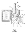
- Fig. 2 is an enlargement of the region of the apparatus of Fig. 1 adjacent to the left hand divider wall 19 where the molten metal 23 of the core layer 12 and the molten metal 24 of the left hand cladding layer 11 come into mutual contact in the mold.
- Metal alloys when cooling from liquid to solid, go through an intermediate semi-solid or "mushy" state when the temperature of the metal is between the liquidus temperature and the solidus temperature of the metal.
- the metal 24 forming the cladding layer 11 has a molten sump region 25, a semi-solid or mushy zone 26 generally below the molten sump, and a fully solid region 27 generally below the mushy zone, but these regions are contoured in the manner shown due to the cooling effects of the mold wall 14 and the divider wall 19.
- the inner surface 28 of the cladding layer 11 immediately below the cooled divider wall 19 is solid, but the shell of solid metal is quite thin as it surrounds the mushy zone 26 and molten sump 25.
- This surface is contacted with the molten metal 23 of the core layer 12 somewhat below the lower end of the divider wall, and heat from the molten metal re-melts a portion of the solid surface 28 of the cladding layer in a shallow region 29 in the shell.
- This re-melting provides good adhesion between the layers at their interface when they solidify.
- the metal of the core layer falls below its liquidus temperature and a mushy zone 30 is formed with solid metal 31 further below.
- the metal of the core layer becomes fully solid, it contracts strongly in the direction of arrows 32, i.e. inwardly towards the center of the ingot, due to its high coefficient of contraction.
- Fracturing of this kind is most likely to occur during the early stage of ingot formation, i.e. during the emergence of the first 12 to 30 inches of the ingot from the mold. This is because of the extra stresses imposed on the ingot at this time by the well-known phenomenon of "butt curl" which is encountered at the start of the casting process.
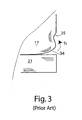
- This phenomenon is illustrated in simplified and exaggerated schematic form in Fig. 3 which shows a region of a bottom of the emerging ingot 17 at one longitudinal end thereof, looking at one of the clad faces.
- the metal contacts the bottom block 21, which has a substantial heat capacity and thus rapidly cools the ingot at its bottom end.
- the ingot is therefore cooled both from the bottom and from the sides (by primary cooling from the cooled mold surfaces and secondary cooling from a water spray or jet 16 contacting the ingot immediately below the mold).
- the cooling influence of the bottom block diminishes because of the increased distance, and cooling then takes place primarily from the sides of the ingot.
- the combination of the cooling from the bottom the cooling from the sides makes the initial region of the ingot curl in the manner shown.
- the lower ends of the ingot feel the influence of a torque ⁇ 1 that lifts the corners of the ingot and causes the wall of the ingot to bow inwardly at 35.
- the initial stage of casting is carried out at a faster rate than the casting that takes place after the initial stage.
- This can create deeper sumps of molten metal in the various layers and this, in turn, increases the contraction force generated by the core metal (the forces being generated along the surface of solidification, as will be explained more fully later). For this reason also, fracture is more likely during the initial stage of casting than later in the process.
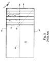
- Fig. 4 is a diagram representing one longitudinal end of a rectangular ingot 17 (showing just the inner layer 12 for simplicity) as it is cast in an apparatus of the kind shown in Fig. 1 .
- the broken line 50 is the line of transition from liquid to solid within the ingot - the so-called line of thermal convergence (more accurately referred to as a surface). It will be seen that the line is quite deep towards the longitudinal center of the ingot where the metal is close to the molten metal feed nozzle 20 ( Fig.
- the line of thermal convergence bifurcates and extends upwardly to each corner of the ingot. This is because of the cooling that takes place from the end surface 54 of the ingot as well as the side surfaces 56 and 58. As the metal solidifies at the line of thermal convergence, contraction takes parallel to the solidification surfaces as shown by arrows A, B and C. At positions on the ingot more central than the bifurcation point 52, the ingot is being cooled, and thus contracts, generally equally from each side surface, but beyond the bifurcation point towards the end of the ingot, the cooling (heat loss) and contraction from the end surface 54 becomes more influential as the end surface is approached. This causes the ingot to curl or torque inwardly at the ends of the side surfaces, as explained in more detail in the following.
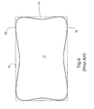
- the ingot takes on a shape illustrated in greatly exaggerated form in Fig. 6 set against a rectangular "ideal" shape 59. It can be seen that the outer surfaces 56 and 58 thus curl inwardly at the extreme ends of the ingot and it is believed that this curl adds to the stresses imposed on the cladding layers and increases the tendency of the layers to separate in this region as the ingot is being cast.
- the outer metal layer (not shown), as it contacts the inner layer or ingot, cannot easily follow this inward turn as it is held back by the divider wall 19. The likelihood of fracture is therefore increased in the end regions.
- the exemplary embodiments overcome this problem by tapering or angling the divider walls 19 at the surface 40 that contacts the metal of the cladding layer(s), and increasing the angle of taper (slope of the surface) of the divider walls at points between the center and the longitudinal ends of the ingot to accommodate both the shrinkage of the ingot and the additional forces produced by butt-curl and in-turning of the core ingot at its longitudinal ends.
- the divider wall 19 may be tapered or angled from the vertical by an angle that is preferably in the range of 0 to 2°, but preferably 1 to 2°.
- the surface 40 of the divider wall 19 that contacts and restrains the metal of the outer or cladding layer slopes inwardly towards the core layer in the direction from top to bottom of the divider wall.
- the angle of taper of the divider wall is increased at the longitudinal ends of the mold, e.g. to a range of 3 to 7°, or more preferably 3 to 4°, for a conventionally-sized ingot.
- the angles selected may depend on the coefficient of contraction of the metal of the inner layer (normally, the higher the coefficient, the higher should be the angle of taper required at both the center and the longitudinal ends).
- the taper angle of the divider wall may be about 1.5° and would stay the same for the entire length of the divider wall.
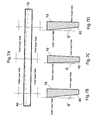
- Figs. 7A to 7D The increase in taper of the divider walls towards their respective ends is illustrated schematically in Figs. 7A to 7D , in which the angle of taper at the center is represented as angle ⁇ , and the angle of taper at the longitudinal ends is represented by angle ⁇ '.
- the angle ⁇ ' at the ends is preferably at least twice the angle ⁇ at the center, but this may depend on the particular alloys employed. Any degree of increase in the angle of taper towards the ends of the divider wall is often found to be beneficial, but the preferred doubling or more gives significant improvements. The most preferred angle for any particular set of circumstances can easily be determined empirically by carrying out test casting operations using different angles and observing the results.
- the mold wall 14 may be vertical or may itself be tapered, i.e. sloping outwardly towards the bottom of the mold (in which case the angle of taper would normally be up to about 1°).
- the angle of taper would normally be up to about 1°.
- the increase in angle of taper of the surface 40 of divider wall 19 may take place gradually and linearly along the length of the divider wall from the center to the longitudinal ends on each longitudinal side. However, it is not always necessary to increase the angle of taper in this way. It is found that, in a region of the divider wall from the center of the mold to a point in line with the start of the bifurcation 52 within the ingot, there may be need for little or no increase in the angle of taper. Therefore, the angle of taper may remain constant in an elongated central region and may then increase in end regions spaced along the divider wall from the center of the mold.
- the increase in may take place gradually, which is preferred, or the angle of taper may increase rapidly to the maximum angle of taper over a short distance at the start of the region and then remain constant throughout the remainder of the region to the ends of the divider wall.
- the positions where the angle of taper commences to increase on each side of the center may be taken as the quarter points of the ingot length. That is to say, the central region of constant (minimum) taper extends across the central region (the second and third quarters) to approximately the quarter and three quarter points along the divider wall, and then the angle of taper increases in the more distant first and fourth quarters.
- a divider wall tapered in this way is shown in Fig. 8 .
- divider wall 19 may also be arched outwardly (in the manner shown in Fig. 7 of U.S. 2005/0011630 ) to accommodate contraction of the long side faces 56 and 58 of the ingot during cooling and solidification. This will compensate for the "bowing-in” of these faces as shown in Fig. 6 and produce side surfaces closer to the ideal planar shape that is desirable for rolling into sheet articles.
- Fig. 9 is a view similar to that of Fig. 1 showing a casting apparatus according to one exemplary embodiment of the invention.
- the figure is split vertically down the center of the casting apparatus.
- the right hand side shows the apparatus in vertical cross-section at the longitudinal center point of the ingot, and the left hand side shows the casting mold at a position towards one longitudinal end of the ingot.
- the thermal bifurcation point 52 is indicated, but the left hand side of the drawing is actually shown as it will appear somewhat beyond this point further towards the end of the ingot.
- the two halves of the drawing show the different angles ( ⁇ and ⁇ ') of divider walls 19 at these different positions as well as the variation in the height of the central solidification point of the metal of the inner layer at these points. It will be seen that the angle of taper ⁇ ' towards the end of the ingot is much greater than at the center (angle ⁇ ).
- the alloy used to cast the inner layer may be a metal having a high coefficient of contraction, for example, a high-Mg or high-Zn aluminum alloy, e.g. an aluminum alloy containing at least 2.5 wt.% Mg, more preferably 2.5 to 15 wt.%, more preferably 2.5 to 9 wt.%, and even more preferably 2.5 to 7 wt.% Mg.
- suitable alloys are generally chosen from AA5xxx series and include alloys AA 5083, 5086, 5454, 5182 and 5754.
- the alloy used for the cladding layer may be one that does not have a high coefficient of contraction, e.g. an aluminum alloy that does not contain any Mg or Zn at all, or one that does not have a very high concentration of Mg or Zn, e.g. an aluminum alloy containing 2 to 3 wt.% Mg or less.
- embodiments of the invention are also of benefit in those cases where there is a significant difference of coefficient of contraction between the metals of the inner and outer layer, even if the metals themselves do not have particularly high coefficients of thermal contraction, because such combinations may also show a tendency towards layer separation.
- the difference of coefficient of contraction is significant if it is large enough to result in occurrences of layer separation.
Landscapes
- Engineering & Computer Science (AREA)
- Mechanical Engineering (AREA)
- Continuous Casting (AREA)
Applications Claiming Priority (2)
| Application Number | Priority Date | Filing Date | Title |
|---|---|---|---|
| US77791406P | 2006-03-01 | 2006-03-01 | |
| PCT/CA2007/000309 WO2007098583A1 (en) | 2006-03-01 | 2007-02-28 | Sequential casting metals having high co-efficients of contraction |
Publications (3)
| Publication Number | Publication Date |
|---|---|
| EP2007535A1 EP2007535A1 (en) | 2008-12-31 |
| EP2007535A4 EP2007535A4 (en) | 2010-07-14 |
| EP2007535B1 true EP2007535B1 (en) | 2013-09-04 |
Family
ID=38458609
Family Applications (1)
| Application Number | Title | Priority Date | Filing Date |
|---|---|---|---|
| EP07710655.7A Active EP2007535B1 (en) | 2006-03-01 | 2007-02-28 | Sequential casting metals having high co-efficients of contraction |
Country Status (13)
| Country | Link |
|---|---|
| US (1) | US7748434B2 (es) |
| EP (1) | EP2007535B1 (es) |
| JP (1) | JP5111401B2 (es) |
| KR (1) | KR101317977B1 (es) |
| CN (1) | CN101394958B (es) |
| AU (1) | AU2007219664B2 (es) |
| BR (1) | BRPI0708261A2 (es) |
| CA (1) | CA2640947C (es) |
| ES (1) | ES2437863T3 (es) |
| NO (1) | NO20084142L (es) |
| RU (1) | RU2416485C2 (es) |
| WO (1) | WO2007098583A1 (es) |
| ZA (1) | ZA200807145B (es) |
Families Citing this family (39)
| Publication number | Priority date | Publication date | Assignee | Title |
|---|---|---|---|---|
| ES2610599T3 (es) | 2003-06-24 | 2017-04-28 | Novelis, Inc. | Método para colar un lingote compuesto |
| US7377304B2 (en) * | 2005-07-12 | 2008-05-27 | Alcoa Inc. | Method of unidirectional solidification of castings and associated apparatus |
| US7617864B2 (en) * | 2006-02-28 | 2009-11-17 | Novelis Inc. | Cladding ingot to prevent hot-tearing |
| US7762310B2 (en) * | 2006-04-13 | 2010-07-27 | Novelis Inc. | Cladding superplastic alloys |
| RU2009133826A (ru) * | 2007-02-28 | 2011-04-10 | Новелис Инк. (Ca) | Совместное литье металлов с прямым охлаждением |
| AU2008291636B2 (en) | 2007-08-29 | 2011-09-15 | Novelis Inc. | Sequential casting of metals having the same or similar co-efficients of contraction |
| US8448690B1 (en) | 2008-05-21 | 2013-05-28 | Alcoa Inc. | Method for producing ingot with variable composition using planar solidification |
| WO2010012099A1 (en) | 2008-07-31 | 2010-02-04 | Novelis Inc. | Sequential casting of metals having similar freezing ranges |
| US20100124668A1 (en) * | 2008-11-14 | 2010-05-20 | Alok Kumar Gupta | Composite aluminum tread plate sheet |
| US20100159266A1 (en) * | 2008-12-23 | 2010-06-24 | Karam Singh Kang | Clad can body stock |
| EP2376281A4 (en) * | 2008-12-23 | 2014-05-21 | Novelis Inc | COATED SHEET AND HEAT EXCHANGER TUBES AND OTHER COMPONENTS MANUFACTURED THEREFROM |
| WO2010071981A1 (en) * | 2008-12-23 | 2010-07-01 | Novelis Inc. | Clad can stock |
| WO2010085888A1 (en) * | 2009-01-29 | 2010-08-05 | Novelis Inc. | Score line corrosion protection for container end walls |
| US20100316887A1 (en) * | 2009-06-16 | 2010-12-16 | Horst Dwenger | Sheet product having an outer surface optimized for anodization |
| MX344421B (es) | 2010-09-08 | 2016-12-15 | Alcoa Inc * | Aleaciones mejoradas de aluminio 7xxx y metodos para producir las mismas. |
| JP2012086250A (ja) * | 2010-10-20 | 2012-05-10 | Toyota Motor Corp | アルミニウム合金クラッド材の製造方法 |
| JP6083812B2 (ja) | 2010-12-22 | 2017-02-22 | ノベリス・インコーポレイテッドNovelis Inc. | 太陽エネルギー吸収ユニット、およびこれを収容する太陽エネルギー装置 |
| CN103658571B (zh) * | 2012-09-04 | 2016-01-06 | 中国兵器科学研究院宁波分院 | 一种层状复合材料半连铸结晶器 |
| EP3237129B1 (en) | 2014-12-22 | 2020-06-24 | Novelis Inc. | Heat exchanger |
| MX2018004508A (es) | 2015-10-15 | 2018-08-01 | Novelis Inc | Empaque de aleacion de aluminio de capas multiples de alta capacidad de formacion. |
| CN106180603A (zh) * | 2016-08-30 | 2016-12-07 | 中国重型机械研究院股份公司 | 镁合金板坯铸造结晶器 |
| JP7163304B2 (ja) | 2017-03-23 | 2022-10-31 | ノベリス・インコーポレイテッド | リサイクルされたアルミニウムスクラップの鋳造 |
| EP3461267B1 (en) | 2017-03-30 | 2022-01-26 | Novelis Inc. | Surface roughening of polymer films |
| EP4056364B1 (en) | 2017-04-24 | 2023-12-13 | Novelis, Inc. | Clad aluminium alloy products and methods of making the same |
| CN107127312B (zh) * | 2017-06-07 | 2022-11-22 | 山东钢铁股份有限公司 | 一种生产复合连铸坯的设备及方法 |
| EP3635148A1 (en) | 2017-08-21 | 2020-04-15 | Novelis Inc. | Aluminum alloy products having selectively recrystallized microstructure and methods of making |
| CA3084467C (en) | 2017-10-23 | 2022-05-31 | Novelis Inc. | Reactive quenching solutions and methods of use |
| CN108526425B (zh) * | 2018-03-30 | 2020-09-01 | 鞍钢股份有限公司 | 一种复合金属连铸装置及连铸方法 |
| MX2021000851A (es) | 2018-07-23 | 2021-03-26 | Novelis Inc | Aleaciones de aluminio recicladas, altamente formables y metodos de fabricacion de las mismas. |
| CN109465410A (zh) * | 2018-12-21 | 2019-03-15 | 西南铝业(集团)有限责任公司 | 一种高锌变形铝合金大圆铸锭的生产工艺 |
| CN113438993A (zh) | 2019-02-13 | 2021-09-24 | 诺维尔里斯公司 | 具有高晶粒圆度的铸造金属产品 |
| ES2964962T3 (es) | 2019-03-13 | 2024-04-10 | Novelis Inc | Aleaciones de aluminio endurecibles por envejecimiento y altamente conformables, chapa monolítica y productos de aleación de aluminio revestidos que la contengan |
| CN115243883A (zh) | 2020-01-21 | 2022-10-25 | 诺维尔里斯公司 | 具有高耐腐蚀性的铝合金和涂层铝合金及其制造方法 |
| US20230227980A1 (en) | 2020-06-10 | 2023-07-20 | Novelis Inc. | Aluminum alloy pretreatment with phosphorus- containing organic acids for surface modification |
| EP4221914A1 (en) | 2020-10-01 | 2023-08-09 | Novelis, Inc. | Direct chill cast aluminum ingot with composition gradient for reduced cracking |
| KR20240058902A (ko) | 2021-09-09 | 2024-05-03 | 노벨리스 인크. | 낮은 로핑을 갖는 알루미늄 합금 물품 및 이의 제조 방법 |
| CA3228948A1 (en) | 2021-09-24 | 2023-03-30 | Novelis Inc. | Surface treatment of metal substrates simultaneous with solution heat treatment or continuous annealing |
| WO2023244770A1 (en) | 2022-06-17 | 2023-12-21 | Novelis Inc. | Recycled aluminum alloys for use in current collectors in lithium-ion batteries |
| CN115319035B (zh) * | 2022-08-19 | 2023-10-31 | 眉山市博眉启明星铝业有限公司 | 一种铝锭连铸生产线浇铸装置 |
Family Cites Families (13)
| Publication number | Priority date | Publication date | Assignee | Title |
|---|---|---|---|---|
| US3212142A (en) | 1962-02-15 | 1965-10-19 | Reynolds Metals Co | Continuous casting system |
| US3353934A (en) | 1962-08-14 | 1967-11-21 | Reynolds Metals Co | Composite-ingot |
| JPS5231814B1 (es) * | 1970-12-08 | 1977-08-17 | ||
| US3717197A (en) * | 1971-01-15 | 1973-02-20 | Mannesmann Ag | Mold for continuous casting of slab ingots |
| US4567936A (en) * | 1984-08-20 | 1986-02-04 | Kaiser Aluminum & Chemical Corporation | Composite ingot casting |
| JPS62104625A (ja) * | 1985-10-31 | 1987-05-15 | Kawasaki Steel Corp | 2層クラツド金属板の反り矯正方法 |
| US6495269B1 (en) * | 1996-12-03 | 2002-12-17 | Corus Aluminium Walzprodukte Gmbh | Multilayer metal composite products obtained by compound strand casting |
| IT1293817B1 (it) * | 1997-08-04 | 1999-03-10 | Giovanni Arvedi | Lingottiera per la colata continua di bramme d'acciaio a contatto migliorato |
| US6158498A (en) * | 1997-10-21 | 2000-12-12 | Wagstaff, Inc. | Casting of molten metal in an open ended mold cavity |
| US6705384B2 (en) * | 2001-10-23 | 2004-03-16 | Alcoa Inc. | Simultaneous multi-alloy casting |
| ES2610599T3 (es) * | 2003-06-24 | 2017-04-28 | Novelis, Inc. | Método para colar un lingote compuesto |
| US7617864B2 (en) | 2006-02-28 | 2009-11-17 | Novelis Inc. | Cladding ingot to prevent hot-tearing |
| US7762310B2 (en) | 2006-04-13 | 2010-07-27 | Novelis Inc. | Cladding superplastic alloys |
-
2007
- 2007-02-28 CA CA2640947A patent/CA2640947C/en active Active
- 2007-02-28 RU RU2008138425/02A patent/RU2416485C2/ru active
- 2007-02-28 BR BRPI0708261-4A patent/BRPI0708261A2/pt not_active Application Discontinuation
- 2007-02-28 KR KR1020087023952A patent/KR101317977B1/ko active IP Right Grant
- 2007-02-28 ES ES07710655.7T patent/ES2437863T3/es active Active
- 2007-02-28 US US11/712,672 patent/US7748434B2/en active Active
- 2007-02-28 JP JP2008556620A patent/JP5111401B2/ja active Active
- 2007-02-28 EP EP07710655.7A patent/EP2007535B1/en active Active
- 2007-02-28 AU AU2007219664A patent/AU2007219664B2/en not_active Ceased
- 2007-02-28 WO PCT/CA2007/000309 patent/WO2007098583A1/en active Application Filing
- 2007-02-28 ZA ZA200807145A patent/ZA200807145B/xx unknown
- 2007-02-28 CN CN2007800073034A patent/CN101394958B/zh active Active
-
2008
- 2008-10-01 NO NO20084142A patent/NO20084142L/no not_active Application Discontinuation
Also Published As
| Publication number | Publication date |
|---|---|
| JP2009528169A (ja) | 2009-08-06 |
| KR20080104168A (ko) | 2008-12-01 |
| NO20084142L (no) | 2008-11-26 |
| RU2008138425A (ru) | 2010-04-10 |
| JP5111401B2 (ja) | 2013-01-09 |
| EP2007535A1 (en) | 2008-12-31 |
| CA2640947C (en) | 2011-09-20 |
| CA2640947A1 (en) | 2007-09-07 |
| US20070215313A1 (en) | 2007-09-20 |
| BRPI0708261A2 (pt) | 2011-05-24 |
| WO2007098583A1 (en) | 2007-09-07 |
| AU2007219664B2 (en) | 2011-03-17 |
| KR101317977B1 (ko) | 2013-10-14 |
| CN101394958A (zh) | 2009-03-25 |
| RU2416485C2 (ru) | 2011-04-20 |
| EP2007535A4 (en) | 2010-07-14 |
| CN101394958B (zh) | 2011-12-21 |
| ES2437863T3 (es) | 2014-01-14 |
| AU2007219664A1 (en) | 2007-09-07 |
| US7748434B2 (en) | 2010-07-06 |
| ZA200807145B (en) | 2009-12-30 |
Similar Documents
| Publication | Publication Date | Title |
|---|---|---|
| EP2007535B1 (en) | Sequential casting metals having high co-efficients of contraction | |
| EP2188079B1 (en) | Sequential casting of metals having the same or similar co-efficients of contraction | |
| US8927113B2 (en) | Composite metal ingot | |
| Emley | Continuous casting of aluminium | |
| US7617864B2 (en) | Cladding ingot to prevent hot-tearing | |
| US8096344B2 (en) | Sequential casting of metals having similar freezing ranges | |
| US8336603B2 (en) | Oxide restraint during co-casting of metals |
Legal Events
| Date | Code | Title | Description |
|---|---|---|---|
| PUAI | Public reference made under article 153(3) epc to a published international application that has entered the european phase |
Free format text: ORIGINAL CODE: 0009012 |
|
| 17P | Request for examination filed |
Effective date: 20080820 |
|
| AK | Designated contracting states |
Kind code of ref document: A1 Designated state(s): AT BE BG CH CY CZ DE DK EE ES FI FR GB GR HU IE IS IT LI LT LU LV MC NL PL PT RO SE SI SK TR |
|
| AX | Request for extension of the european patent |
Extension state: AL BA HR MK RS |
|
| A4 | Supplementary search report drawn up and despatched |
Effective date: 20100614 |
|
| 17Q | First examination report despatched |
Effective date: 20110811 |
|
| DAX | Request for extension of the european patent (deleted) | ||
| REG | Reference to a national code |
Ref country code: DE Ref legal event code: R079 Ref document number: 602007032645 Country of ref document: DE Free format text: PREVIOUS MAIN CLASS: B22D0007020000 Ipc: B22D0011000000 |
|
| GRAP | Despatch of communication of intention to grant a patent |
Free format text: ORIGINAL CODE: EPIDOSNIGR1 |
|
| RIC1 | Information provided on ipc code assigned before grant |
Ipc: B22D 11/00 20060101AFI20130308BHEP |
|
| INTG | Intention to grant announced |
Effective date: 20130402 |
|
| GRAS | Grant fee paid |
Free format text: ORIGINAL CODE: EPIDOSNIGR3 |
|
| GRAA | (expected) grant |
Free format text: ORIGINAL CODE: 0009210 |
|
| AK | Designated contracting states |
Kind code of ref document: B1 Designated state(s): AT BE BG CH CY CZ DE DK EE ES FI FR GB GR HU IE IS IT LI LT LU LV MC NL PL PT RO SE SI SK TR |
|
| REG | Reference to a national code |
Ref country code: GB Ref legal event code: FG4D |
|
| REG | Reference to a national code |
Ref country code: CH Ref legal event code: NV Representative=s name: E. BLUM AND CO. AG PATENT- UND MARKENANWAELTE , CH Ref country code: CH Ref legal event code: EP |
|
| REG | Reference to a national code |
Ref country code: AT Ref legal event code: REF Ref document number: 630200 Country of ref document: AT Kind code of ref document: T Effective date: 20130915 |
|
| REG | Reference to a national code |
Ref country code: IE Ref legal event code: FG4D |
|
| REG | Reference to a national code |
Ref country code: CH Ref legal event code: PCOW Free format text: NEW ADDRESS: 3560 LENOX ROAD SUITE 2000, ATLANTA, GA 30326 (US) |
|
| REG | Reference to a national code |
Ref country code: DE Ref legal event code: R096 Ref document number: 602007032645 Country of ref document: DE Effective date: 20131031 |
|
| RAP2 | Party data changed (patent owner data changed or rights of a patent transferred) |
Owner name: NOVELIS INC. |
|
| REG | Reference to a national code |
Ref country code: ES Ref legal event code: FG2A Ref document number: 2437863 Country of ref document: ES Kind code of ref document: T3 Effective date: 20140114 |
|
| REG | Reference to a national code |
Ref country code: NL Ref legal event code: VDEP Effective date: 20130904 |
|
| PG25 | Lapsed in a contracting state [announced via postgrant information from national office to epo] |
Ref country code: CY Free format text: LAPSE BECAUSE OF FAILURE TO SUBMIT A TRANSLATION OF THE DESCRIPTION OR TO PAY THE FEE WITHIN THE PRESCRIBED TIME-LIMIT Effective date: 20130619 Ref country code: LT Free format text: LAPSE BECAUSE OF FAILURE TO SUBMIT A TRANSLATION OF THE DESCRIPTION OR TO PAY THE FEE WITHIN THE PRESCRIBED TIME-LIMIT Effective date: 20130904 Ref country code: SE Free format text: LAPSE BECAUSE OF FAILURE TO SUBMIT A TRANSLATION OF THE DESCRIPTION OR TO PAY THE FEE WITHIN THE PRESCRIBED TIME-LIMIT Effective date: 20130904 |
|
| REG | Reference to a national code |
Ref country code: NL Ref legal event code: VDEP Effective date: 20130904 |
|
| REG | Reference to a national code |
Ref country code: LT Ref legal event code: MG4D |
|
| PG25 | Lapsed in a contracting state [announced via postgrant information from national office to epo] |
Ref country code: SI Free format text: LAPSE BECAUSE OF FAILURE TO SUBMIT A TRANSLATION OF THE DESCRIPTION OR TO PAY THE FEE WITHIN THE PRESCRIBED TIME-LIMIT Effective date: 20130904 Ref country code: LV Free format text: LAPSE BECAUSE OF FAILURE TO SUBMIT A TRANSLATION OF THE DESCRIPTION OR TO PAY THE FEE WITHIN THE PRESCRIBED TIME-LIMIT Effective date: 20130904 Ref country code: FI Free format text: LAPSE BECAUSE OF FAILURE TO SUBMIT A TRANSLATION OF THE DESCRIPTION OR TO PAY THE FEE WITHIN THE PRESCRIBED TIME-LIMIT Effective date: 20130904 Ref country code: PL Free format text: LAPSE BECAUSE OF FAILURE TO SUBMIT A TRANSLATION OF THE DESCRIPTION OR TO PAY THE FEE WITHIN THE PRESCRIBED TIME-LIMIT Effective date: 20130904 Ref country code: GR Free format text: LAPSE BECAUSE OF FAILURE TO SUBMIT A TRANSLATION OF THE DESCRIPTION OR TO PAY THE FEE WITHIN THE PRESCRIBED TIME-LIMIT Effective date: 20131205 |
|
| PG25 | Lapsed in a contracting state [announced via postgrant information from national office to epo] |
Ref country code: BE Free format text: LAPSE BECAUSE OF FAILURE TO SUBMIT A TRANSLATION OF THE DESCRIPTION OR TO PAY THE FEE WITHIN THE PRESCRIBED TIME-LIMIT Effective date: 20130904 Ref country code: CY Free format text: LAPSE BECAUSE OF FAILURE TO SUBMIT A TRANSLATION OF THE DESCRIPTION OR TO PAY THE FEE WITHIN THE PRESCRIBED TIME-LIMIT Effective date: 20130904 |
|
| PG25 | Lapsed in a contracting state [announced via postgrant information from national office to epo] |
Ref country code: CZ Free format text: LAPSE BECAUSE OF FAILURE TO SUBMIT A TRANSLATION OF THE DESCRIPTION OR TO PAY THE FEE WITHIN THE PRESCRIBED TIME-LIMIT Effective date: 20130904 Ref country code: NL Free format text: LAPSE BECAUSE OF FAILURE TO SUBMIT A TRANSLATION OF THE DESCRIPTION OR TO PAY THE FEE WITHIN THE PRESCRIBED TIME-LIMIT Effective date: 20130904 Ref country code: EE Free format text: LAPSE BECAUSE OF FAILURE TO SUBMIT A TRANSLATION OF THE DESCRIPTION OR TO PAY THE FEE WITHIN THE PRESCRIBED TIME-LIMIT Effective date: 20130904 Ref country code: SK Free format text: LAPSE BECAUSE OF FAILURE TO SUBMIT A TRANSLATION OF THE DESCRIPTION OR TO PAY THE FEE WITHIN THE PRESCRIBED TIME-LIMIT Effective date: 20130904 Ref country code: RO Free format text: LAPSE BECAUSE OF FAILURE TO SUBMIT A TRANSLATION OF THE DESCRIPTION OR TO PAY THE FEE WITHIN THE PRESCRIBED TIME-LIMIT Effective date: 20130904 Ref country code: IS Free format text: LAPSE BECAUSE OF FAILURE TO SUBMIT A TRANSLATION OF THE DESCRIPTION OR TO PAY THE FEE WITHIN THE PRESCRIBED TIME-LIMIT Effective date: 20140104 |
|
| REG | Reference to a national code |
Ref country code: DE Ref legal event code: R097 Ref document number: 602007032645 Country of ref document: DE |
|
| PG25 | Lapsed in a contracting state [announced via postgrant information from national office to epo] |
Ref country code: PT Free format text: LAPSE BECAUSE OF FAILURE TO SUBMIT A TRANSLATION OF THE DESCRIPTION OR TO PAY THE FEE WITHIN THE PRESCRIBED TIME-LIMIT Effective date: 20140106 |
|
| PLBE | No opposition filed within time limit |
Free format text: ORIGINAL CODE: 0009261 |
|
| STAA | Information on the status of an ep patent application or granted ep patent |
Free format text: STATUS: NO OPPOSITION FILED WITHIN TIME LIMIT |
|
| 26N | No opposition filed |
Effective date: 20140605 |
|
| REG | Reference to a national code |
Ref country code: DE Ref legal event code: R097 Ref document number: 602007032645 Country of ref document: DE Effective date: 20140605 |
|
| PG25 | Lapsed in a contracting state [announced via postgrant information from national office to epo] |
Ref country code: DK Free format text: LAPSE BECAUSE OF FAILURE TO SUBMIT A TRANSLATION OF THE DESCRIPTION OR TO PAY THE FEE WITHIN THE PRESCRIBED TIME-LIMIT Effective date: 20130904 Ref country code: MC Free format text: LAPSE BECAUSE OF FAILURE TO SUBMIT A TRANSLATION OF THE DESCRIPTION OR TO PAY THE FEE WITHIN THE PRESCRIBED TIME-LIMIT Effective date: 20130904 Ref country code: LU Free format text: LAPSE BECAUSE OF FAILURE TO SUBMIT A TRANSLATION OF THE DESCRIPTION OR TO PAY THE FEE WITHIN THE PRESCRIBED TIME-LIMIT Effective date: 20140228 |
|
| REG | Reference to a national code |
Ref country code: IE Ref legal event code: MM4A |
|
| PG25 | Lapsed in a contracting state [announced via postgrant information from national office to epo] |
Ref country code: IE Free format text: LAPSE BECAUSE OF NON-PAYMENT OF DUE FEES Effective date: 20140228 |
|
| REG | Reference to a national code |
Ref country code: FR Ref legal event code: PLFP Year of fee payment: 10 |
|
| PG25 | Lapsed in a contracting state [announced via postgrant information from national office to epo] |
Ref country code: BG Free format text: LAPSE BECAUSE OF FAILURE TO SUBMIT A TRANSLATION OF THE DESCRIPTION OR TO PAY THE FEE WITHIN THE PRESCRIBED TIME-LIMIT Effective date: 20130904 |
|
| PG25 | Lapsed in a contracting state [announced via postgrant information from national office to epo] |
Ref country code: TR Free format text: LAPSE BECAUSE OF FAILURE TO SUBMIT A TRANSLATION OF THE DESCRIPTION OR TO PAY THE FEE WITHIN THE PRESCRIBED TIME-LIMIT Effective date: 20130904 Ref country code: HU Free format text: LAPSE BECAUSE OF FAILURE TO SUBMIT A TRANSLATION OF THE DESCRIPTION OR TO PAY THE FEE WITHIN THE PRESCRIBED TIME-LIMIT; INVALID AB INITIO Effective date: 20070228 |
|
| REG | Reference to a national code |
Ref country code: FR Ref legal event code: PLFP Year of fee payment: 11 |
|
| REG | Reference to a national code |
Ref country code: FR Ref legal event code: PLFP Year of fee payment: 12 |
|
| PGFP | Annual fee paid to national office [announced via postgrant information from national office to epo] |
Ref country code: AT Payment date: 20200123 Year of fee payment: 14 Ref country code: IT Payment date: 20200121 Year of fee payment: 14 Ref country code: ES Payment date: 20200302 Year of fee payment: 14 |
|
| REG | Reference to a national code |
Ref country code: AT Ref legal event code: MM01 Ref document number: 630200 Country of ref document: AT Kind code of ref document: T Effective date: 20210228 |
|
| PG25 | Lapsed in a contracting state [announced via postgrant information from national office to epo] |
Ref country code: AT Free format text: LAPSE BECAUSE OF NON-PAYMENT OF DUE FEES Effective date: 20210228 |
|
| PG25 | Lapsed in a contracting state [announced via postgrant information from national office to epo] |
Ref country code: IT Free format text: LAPSE BECAUSE OF NON-PAYMENT OF DUE FEES Effective date: 20210228 |
|
| REG | Reference to a national code |
Ref country code: ES Ref legal event code: FD2A Effective date: 20220517 |
|
| PG25 | Lapsed in a contracting state [announced via postgrant information from national office to epo] |
Ref country code: ES Free format text: LAPSE BECAUSE OF NON-PAYMENT OF DUE FEES Effective date: 20210301 |
|
| PGFP | Annual fee paid to national office [announced via postgrant information from national office to epo] |
Ref country code: FR Payment date: 20230119 Year of fee payment: 17 |
|
| P01 | Opt-out of the competence of the unified patent court (upc) registered |
Effective date: 20230517 |
|
| PGFP | Annual fee paid to national office [announced via postgrant information from national office to epo] |
Ref country code: DE Payment date: 20240123 Year of fee payment: 18 Ref country code: GB Payment date: 20240123 Year of fee payment: 18 Ref country code: CH Payment date: 20240301 Year of fee payment: 18 |