EP4056364B1 - Clad aluminium alloy products and methods of making the same - Google Patents
Clad aluminium alloy products and methods of making the same Download PDFInfo
- Publication number
- EP4056364B1 EP4056364B1 EP22165096.3A EP22165096A EP4056364B1 EP 4056364 B1 EP4056364 B1 EP 4056364B1 EP 22165096 A EP22165096 A EP 22165096A EP 4056364 B1 EP4056364 B1 EP 4056364B1
- Authority
- EP
- European Patent Office
- Prior art keywords
- alloy
- aluminum alloy
- clad
- clad aluminum
- cladding layer
- Prior art date
- Legal status (The legal status is an assumption and is not a legal conclusion. Google has not performed a legal analysis and makes no representation as to the accuracy of the status listed.)
- Active
Links
- 229910000838 Al alloy Inorganic materials 0.000 title claims description 136
- 238000000034 method Methods 0.000 title description 42
- 229910045601 alloy Inorganic materials 0.000 claims description 159
- 239000000956 alloy Substances 0.000 claims description 159
- 239000010410 layer Substances 0.000 claims description 89
- 238000005253 cladding Methods 0.000 claims description 69
- 239000012792 core layer Substances 0.000 claims description 55
- 229910052782 aluminium Inorganic materials 0.000 claims description 17
- XAGFODPZIPBFFR-UHFFFAOYSA-N aluminium Chemical compound [Al] XAGFODPZIPBFFR-UHFFFAOYSA-N 0.000 claims description 17
- 239000012535 impurity Substances 0.000 claims description 12
- 229910052802 copper Inorganic materials 0.000 claims description 7
- 229910052749 magnesium Inorganic materials 0.000 claims description 7
- 229910052804 chromium Inorganic materials 0.000 claims description 6
- 229910052748 manganese Inorganic materials 0.000 claims description 6
- 229910052710 silicon Inorganic materials 0.000 claims description 6
- 229910052725 zinc Inorganic materials 0.000 claims description 6
- 229910052742 iron Inorganic materials 0.000 claims description 5
- 229910052726 zirconium Inorganic materials 0.000 claims description 5
- 239000000047 product Substances 0.000 description 102
- 230000032683 aging Effects 0.000 description 60
- 239000000523 sample Substances 0.000 description 37
- 238000010438 heat treatment Methods 0.000 description 36
- 230000000052 comparative effect Effects 0.000 description 19
- 230000000694 effects Effects 0.000 description 19
- 230000007797 corrosion Effects 0.000 description 15
- 238000005260 corrosion Methods 0.000 description 15
- 238000005266 casting Methods 0.000 description 13
- 239000000203 mixture Substances 0.000 description 13
- 238000010791 quenching Methods 0.000 description 13
- 238000003466 welding Methods 0.000 description 12
- 239000011701 zinc Substances 0.000 description 12
- 239000011777 magnesium Substances 0.000 description 11
- 239000000463 material Substances 0.000 description 11
- 239000011651 chromium Substances 0.000 description 10
- 239000013068 control sample Substances 0.000 description 10
- 239000010949 copper Substances 0.000 description 10
- 238000005098 hot rolling Methods 0.000 description 10
- 239000011572 manganese Substances 0.000 description 10
- 238000000265 homogenisation Methods 0.000 description 9
- XEEYBQQBJWHFJM-UHFFFAOYSA-N iron Substances [Fe] XEEYBQQBJWHFJM-UHFFFAOYSA-N 0.000 description 9
- 238000001000 micrograph Methods 0.000 description 8
- 230000008569 process Effects 0.000 description 8
- 238000012360 testing method Methods 0.000 description 8
- XLYOFNOQVPJJNP-UHFFFAOYSA-N water Substances O XLYOFNOQVPJJNP-UHFFFAOYSA-N 0.000 description 8
- 238000001816 cooling Methods 0.000 description 7
- 238000005304 joining Methods 0.000 description 7
- 239000003973 paint Substances 0.000 description 7
- 238000005097 cold rolling Methods 0.000 description 6
- 239000010432 diamond Substances 0.000 description 6
- 229910052751 metal Inorganic materials 0.000 description 6
- 239000002184 metal Substances 0.000 description 6
- 238000012545 processing Methods 0.000 description 6
- 239000000126 substance Substances 0.000 description 6
- 238000011282 treatment Methods 0.000 description 6
- 241000206607 Porphyra umbilicalis Species 0.000 description 5
- 229910052799 carbon Inorganic materials 0.000 description 4
- 238000009749 continuous casting Methods 0.000 description 4
- 239000011261 inert gas Substances 0.000 description 4
- 238000004519 manufacturing process Methods 0.000 description 4
- 239000011324 bead Substances 0.000 description 3
- 230000035515 penetration Effects 0.000 description 3
- 239000007787 solid Substances 0.000 description 3
- RYGMFSIKBFXOCR-UHFFFAOYSA-N Copper Chemical compound [Cu] RYGMFSIKBFXOCR-UHFFFAOYSA-N 0.000 description 2
- FYYHWMGAXLPEAU-UHFFFAOYSA-N Magnesium Chemical compound [Mg] FYYHWMGAXLPEAU-UHFFFAOYSA-N 0.000 description 2
- 238000004026 adhesive bonding Methods 0.000 description 2
- 238000003483 aging Methods 0.000 description 2
- 238000000137 annealing Methods 0.000 description 2
- 229910052797 bismuth Inorganic materials 0.000 description 2
- 239000002131 composite material Substances 0.000 description 2
- 238000005336 cracking Methods 0.000 description 2
- 239000000945 filler Substances 0.000 description 2
- 239000000446 fuel Substances 0.000 description 2
- 229910052759 nickel Inorganic materials 0.000 description 2
- 230000000171 quenching effect Effects 0.000 description 2
- 230000009467 reduction Effects 0.000 description 2
- 238000005096 rolling process Methods 0.000 description 2
- 238000002791 soaking Methods 0.000 description 2
- 229910052708 sodium Inorganic materials 0.000 description 2
- 238000003756 stirring Methods 0.000 description 2
- 229910052718 tin Inorganic materials 0.000 description 2
- WFKWXMTUELFFGS-UHFFFAOYSA-N tungsten Chemical compound [W] WFKWXMTUELFFGS-UHFFFAOYSA-N 0.000 description 2
- 229910052721 tungsten Inorganic materials 0.000 description 2
- 239000010937 tungsten Substances 0.000 description 2
- 229910052720 vanadium Inorganic materials 0.000 description 2
- OKTJSMMVPCPJKN-UHFFFAOYSA-N Carbon Chemical compound [C] OKTJSMMVPCPJKN-UHFFFAOYSA-N 0.000 description 1
- VYZAMTAEIAYCRO-UHFFFAOYSA-N Chromium Chemical compound [Cr] VYZAMTAEIAYCRO-UHFFFAOYSA-N 0.000 description 1
- PWHULOQIROXLJO-UHFFFAOYSA-N Manganese Chemical compound [Mn] PWHULOQIROXLJO-UHFFFAOYSA-N 0.000 description 1
- 241000830107 Pediomelum Species 0.000 description 1
- XUIMIQQOPSSXEZ-UHFFFAOYSA-N Silicon Chemical compound [Si] XUIMIQQOPSSXEZ-UHFFFAOYSA-N 0.000 description 1
- 229910000831 Steel Inorganic materials 0.000 description 1
- HCHKCACWOHOZIP-UHFFFAOYSA-N Zinc Chemical compound [Zn] HCHKCACWOHOZIP-UHFFFAOYSA-N 0.000 description 1
- 238000004458 analytical method Methods 0.000 description 1
- 238000005452 bending Methods 0.000 description 1
- 238000004140 cleaning Methods 0.000 description 1
- 239000011248 coating agent Substances 0.000 description 1
- 238000000576 coating method Methods 0.000 description 1
- 230000003247 decreasing effect Effects 0.000 description 1
- 238000011143 downstream manufacturing Methods 0.000 description 1
- 238000005516 engineering process Methods 0.000 description 1
- 238000004299 exfoliation Methods 0.000 description 1
- 238000002474 experimental method Methods 0.000 description 1
- 239000012467 final product Substances 0.000 description 1
- 230000004927 fusion Effects 0.000 description 1
- 238000009957 hemming Methods 0.000 description 1
- 230000006698 induction Effects 0.000 description 1
- 238000002955 isolation Methods 0.000 description 1
- 229910052745 lead Inorganic materials 0.000 description 1
- 238000012986 modification Methods 0.000 description 1
- 230000004048 modification Effects 0.000 description 1
- 239000002245 particle Substances 0.000 description 1
- 238000001953 recrystallisation Methods 0.000 description 1
- 238000003303 reheating Methods 0.000 description 1
- 230000002787 reinforcement Effects 0.000 description 1
- VSZWPYCFIRKVQL-UHFFFAOYSA-N selanylidenegallium;selenium Chemical compound [Se].[Se]=[Ga].[Se]=[Ga] VSZWPYCFIRKVQL-UHFFFAOYSA-N 0.000 description 1
- 239000010703 silicon Substances 0.000 description 1
- 238000007655 standard test method Methods 0.000 description 1
- 239000010959 steel Substances 0.000 description 1
- 238000004381 surface treatment Methods 0.000 description 1
- JBQYATWDVHIOAR-UHFFFAOYSA-N tellanylidenegermanium Chemical compound [Te]=[Ge] JBQYATWDVHIOAR-UHFFFAOYSA-N 0.000 description 1
- 230000007704 transition Effects 0.000 description 1
Images


Classifications
-
- C—CHEMISTRY; METALLURGY
- C22—METALLURGY; FERROUS OR NON-FERROUS ALLOYS; TREATMENT OF ALLOYS OR NON-FERROUS METALS
- C22C—ALLOYS
- C22C21/00—Alloys based on aluminium
- C22C21/10—Alloys based on aluminium with zinc as the next major constituent
-
- B—PERFORMING OPERATIONS; TRANSPORTING
- B32—LAYERED PRODUCTS
- B32B—LAYERED PRODUCTS, i.e. PRODUCTS BUILT-UP OF STRATA OF FLAT OR NON-FLAT, e.g. CELLULAR OR HONEYCOMB, FORM
- B32B15/00—Layered products comprising a layer of metal
- B32B15/01—Layered products comprising a layer of metal all layers being exclusively metallic
- B32B15/016—Layered products comprising a layer of metal all layers being exclusively metallic all layers being formed of aluminium or aluminium alloys
-
- B—PERFORMING OPERATIONS; TRANSPORTING
- B32—LAYERED PRODUCTS
- B32B—LAYERED PRODUCTS, i.e. PRODUCTS BUILT-UP OF STRATA OF FLAT OR NON-FLAT, e.g. CELLULAR OR HONEYCOMB, FORM
- B32B15/00—Layered products comprising a layer of metal
- B32B15/01—Layered products comprising a layer of metal all layers being exclusively metallic
-
- C—CHEMISTRY; METALLURGY
- C22—METALLURGY; FERROUS OR NON-FERROUS ALLOYS; TREATMENT OF ALLOYS OR NON-FERROUS METALS
- C22C—ALLOYS
- C22C21/00—Alloys based on aluminium
- C22C21/02—Alloys based on aluminium with silicon as the next major constituent
-
- C—CHEMISTRY; METALLURGY
- C22—METALLURGY; FERROUS OR NON-FERROUS ALLOYS; TREATMENT OF ALLOYS OR NON-FERROUS METALS
- C22C—ALLOYS
- C22C21/00—Alloys based on aluminium
- C22C21/06—Alloys based on aluminium with magnesium as the next major constituent
- C22C21/08—Alloys based on aluminium with magnesium as the next major constituent with silicon
-
- C—CHEMISTRY; METALLURGY
- C22—METALLURGY; FERROUS OR NON-FERROUS ALLOYS; TREATMENT OF ALLOYS OR NON-FERROUS METALS
- C22F—CHANGING THE PHYSICAL STRUCTURE OF NON-FERROUS METALS AND NON-FERROUS ALLOYS
- C22F1/00—Changing the physical structure of non-ferrous metals or alloys by heat treatment or by hot or cold working
- C22F1/002—Changing the physical structure of non-ferrous metals or alloys by heat treatment or by hot or cold working by rapid cooling or quenching; cooling agents used therefor
-
- C—CHEMISTRY; METALLURGY
- C22—METALLURGY; FERROUS OR NON-FERROUS ALLOYS; TREATMENT OF ALLOYS OR NON-FERROUS METALS
- C22F—CHANGING THE PHYSICAL STRUCTURE OF NON-FERROUS METALS AND NON-FERROUS ALLOYS
- C22F1/00—Changing the physical structure of non-ferrous metals or alloys by heat treatment or by hot or cold working
- C22F1/04—Changing the physical structure of non-ferrous metals or alloys by heat treatment or by hot or cold working of aluminium or alloys based thereon
- C22F1/053—Changing the physical structure of non-ferrous metals or alloys by heat treatment or by hot or cold working of aluminium or alloys based thereon of alloys with zinc as the next major constituent
-
- Y—GENERAL TAGGING OF NEW TECHNOLOGICAL DEVELOPMENTS; GENERAL TAGGING OF CROSS-SECTIONAL TECHNOLOGIES SPANNING OVER SEVERAL SECTIONS OF THE IPC; TECHNICAL SUBJECTS COVERED BY FORMER USPC CROSS-REFERENCE ART COLLECTIONS [XRACs] AND DIGESTS
- Y10—TECHNICAL SUBJECTS COVERED BY FORMER USPC
- Y10T—TECHNICAL SUBJECTS COVERED BY FORMER US CLASSIFICATION
- Y10T428/00—Stock material or miscellaneous articles
- Y10T428/12—All metal or with adjacent metals
- Y10T428/12493—Composite; i.e., plural, adjacent, spatially distinct metal components [e.g., layers, joint, etc.]
- Y10T428/12736—Al-base component
- Y10T428/12764—Next to Al-base component
Definitions
- novel clad aluminum alloy products are provided herein.
- the clad alloy products are suitable for a variety of applications, including automotive and electronic applications.
- the clad alloy products display high strength and corrosion resistance properties.
- an aluminum alloy product must offer the best combination of high strength and other key attributes, such as corrosion resistance, formability, and joining ability.
- 7xxx series aluminum alloys are prime candidates for high end strength applications.
- an increase in strength typically results in a lowering of the aforementioned key attributes.
- strength and corrosion resistance performance tend to be inversely related for 7xxx series alloys, meaning that while the alloys have high strength, the corrosion resistance performance is limited.
- EP 2 581 218 A1 refers to a 7xxx-series aluminum alloy, which might be present in the form of a composite sheet having a core layer and a cladding layer.
- the core layer can be made from an aluminum alloy of the AA7xxx-series, and the one or several clad layers can be made from an AA3xxx-, AA4xxx-, AA5xxx-, AA6xxx-series alloy or a different AA7xxx-series aluminum alloy compared to the core alloy.
- WO 2012/059505 A1 refers to an AA7000-series alloy, which may optionally be provided with a metal clad layer, such as from an AA3000-, AA4000-, AA5000-, AA6000- or a different AA7000-series aluminum alloy compared to the core.
- Joining methods can include, but are not limited to, resistance spot welding (RSW), friction stir welding, remote laser welding, metal inert gas (MIG) welding, tungsten inert gas (TIG) welding, adhesive bonding, and self-piercing riveting.
- RSW resistance spot welding
- MIG metal inert gas
- TOG tungsten inert gas
- the alloy products can be used in a variety of applications, including automotive, transportation, electronics, and other applications.
- the clad aluminum alloy products described herein comprise a core layer comprising up to 12.0 wt. % Zn, 1.0 to 4.0 wt. % Mg, 0.1 to 3.0 wt. % Cu, up to 0.60 wt. % Si, up to 0.50 wt. % Fe, up to 0.20 wt. % Mn, up to 0.20 wt. % Cr, up to 0.30 wt. % Zr, up to 0.15 wt.
- the core layer has a first side and a second side; and a first cladding layer on the first side of the core layer, wherein the first cladding layer is an AA7xxx series alloy cladding layer selected from AA7011, AA7019, AA7020, AA7021, AA7039, AA7075, AA7085, AA7108, AA7108A, AA7015, AA7017, AA7018, AA7019A, AA7024, AA7025, AA7028, AA7030, AA7031, AA7033, AA7035, AA7035A, AA7046, AA7046A, AA7003, AA7004, AA7005, AA7009, AA7010, AA7011, AA7012, AA7014, AA7016, AA7116, AA7122, AA7023, AA7026, AA7029, AA
- the core layer comprises 5.0 to 9.5 wt. % Zn, 1.2 to 2.3 wt. % Mg, 0.10 to 2.6 wt. % Cu, up to 0.10 wt. % Si, up to 0.15 wt. % Fe, up to 0.05 wt. % Mn, up to 0.05 wt. % Cr, up to 0.25 wt. % Zr, up to 0.15 wt. % impurities, and the balance aluminum.
- the core layer has a thickness of about 0.5 to 3 mm (e.g., from about 0.7 to about 2.3 mm or from about 1 mm to about 2 mm).
- the first cladding layer can have a thickness of about 1% to 25% of the total clad product thickness (e.g., from about 1% to about 12% of the total clad product thickness or about 10% of the total clad product thickness).
- the clad aluminum alloy product described herein can further comprise a second cladding layer located on the second side of the core layer.
- the first cladding layer and the second cladding layer can comprise the same or different alloys.
- the clad aluminum alloy product has a yield strength up to 600 MPa (e.g., up to 550 MPa).
- the clad product can have an elongation up to 20 % (e.g., up to 15 %).
- the materials can include automotive products (e.g., automotive structural parts), aerospace products (e.g., an aerospace structural part or an aerospace non-structural part), marine products (e.g., a marine structural part or a marine non-structural part), or electronic products (e.g., electronic device housings), among others.
- automotive products e.g., automotive structural parts
- aerospace products e.g., an aerospace structural part or an aerospace non-structural part
- marine products e.g., a marine structural part or a marine non-structural part
- electronic products e.g., electronic device housings
- the clad aluminum alloy products include a core layer and one or more cladding layers.
- the core layer which represents the largest component of the material, mainly determines the bulk mechanical properties of the cladded material (e.g., strength).
- the cladding layer(s) which represents a small component of the material, is in contact with the environment surrounding the cladded material and thus determines the chemical activity (e.g., corrosion resistance) and can affect the formability and joining properties of the cladded material.
- Joining methods can include, but are not limited to, resistance spot welding (RSW), friction stir welding (FSW), remote laser welding, metal inert gas (MIG) welding, tungsten inert gas (TIG) welding, adhesive bonding, and self-piercing riveting.
- RSW resistance spot welding
- FSW friction stir welding
- MIG metal inert gas
- TOG tungsten inert gas
- invention As used herein, the terms "invention,” “the invention,” “this invention,” and “the present invention” are intended to refer broadly to all of the subject matter of this patent application and the claims below. Statements containing these terms should be understood not to limit the subject matter described herein or to limit the meaning or scope of the patent claims below.
- a plate generally has a thickness of greater than 15 mm.
- a plate may refer to an aluminum product having a thickness of greater than 15 mm, greater than 20 mm, greater than 25 mm, greater than 30 mm, greater than 35 mm, greater than 40 mm, greater than 45 mm, greater than 50 mm, or greater than 100 mm.
- a shate (also referred to as a sheet plate) generally has a thickness of from 4 mm to 15 mm.
- a shate may have a thickness of 4 mm, 5 mm, 6 mm, 7 mm, 8 mm, 9 mm, 10 mm, 11 mm, 12 mm, 13 mm, 14 mm, or 15 mm.
- a sheet generally refers to an aluminum product having a thickness of less than 4 mm.
- a sheet may have a thickness of less than 4 mm, less than 3 mm, less than 2 mm, less than 1 mm, less than 0.5 mm, less than 0.3 mm, or less than 0.1 mm.
- An F condition or temper refers to an aluminum alloy as fabricated.
- An O condition or temper refers to an aluminum alloy after annealing.
- a T4 condition or temper refers to an aluminum alloy after solution heat treatment (i.e., solutionization) followed by natural aging.
- a T6 condition or temper refers to an aluminum alloy after solution heat treatment followed by artificial aging.
- a T8x condition or temper refers to an aluminum alloy solution heat treated, cold worked, and artificially aged.
- cast metal product As used herein, terms such as "cast metal product,” “cast product,” “cast aluminum alloy product,” and the like are interchangeable and refer to a product produced by direct chill casting (including direct chill co-casting) or semi-continuous casting, continuous casting (including, for example, by use of a twin belt caster, a twin roll caster, a block caster, or any other continuous caster), electromagnetic casting, hot top casting, or any other casting method.
- room temperature can include a temperature of from 15 °C to 30 °C, for example 15 °C, 16 °C, 17 °C, 18 °C, 19 °C, 20 °C, 21 °C, 22 °C, 23 °C, 24 °C, 25 °C, 26 °C, 27 °C, 28 °C, 29 °C, or 30 °C.
- ambient conditions can include temperatures of room temperature, relative humidity of from 20 % to 100 %, and barometric pressure of from 975 millibar (mbar) to 1050 mbar.
- relative humidity can be 20 %, 21 %, 22 %, 23 %, 24 %, 25 %, 26 %, 27 %, 28 %, 29 %, 30 %, 31 %, 32 %, 33 %, 34 %, 35 %, 36 %, 37 %, 38 %, 39 %, 40 %, 41 %, 42 %, 43 %, 44 %, 45 %, 46 %, 47 %, 48 %, 49 %, 50 %, 51 %, 52 %, 53 %, 54%, 55 %, 56 %, 57 %, 58 %, 59 %, 60 %, 61 %, 62 %, 63 %, 64 %, 65 %, 66 %, 67 %, 68 %, 69 %, 70 %, 71 %, 72 %, 73 %, 74 %, 75 %, 76 %, 77 %, 78
- barometric pressure can be 975 mbar, 980 mbar, 985 mbar, 990 mbar, 995 mbar, 1000 mbar, 1005 mbar, 1010 mbar, 1015 mbar, 1020 mbar, 1025 mbar, 1030 mbar, 1035 mbar, 1040 mbar, 1045 mbar, 1050 mbar, or anywhere in between.
- the aluminum alloy products and their components are described in terms of their elemental composition in weight percent (wt. %).
- the remainder is aluminum, with a maximum wt. % of 0.15 % for the sum of all impurities.
- the clad aluminum alloy products include a core layer of an aluminum alloy having a first side and a second side and one or more cladding layer(s) bonded to the first side or the second side of the core layer.
- the core layer is clad on only one side (i.e., one cladding layer is present in the clad aluminum alloy product).
- the core layer is clad on both sides (i.e., two cladding layers are present in the clad aluminum alloy product).
- the first side of the core layer is adjacent to and contacts a first cladding layer to form a first interface.
- the clad aluminum alloy product includes a second cladding layer.
- the second side of the core layer is adjacent to and contacts a second cladding layer to form a second interface (i.e., no layers intervene between the second cladding layer and the second side of the core layer).
- the first cladding layer and the second cladding layer can be the same chemical composition or different chemical compositions.
- the core layer is an aluminum-containing alloy.
- the alloy for use as the core layer has the following elemental composition as provided in Table 1.
- Table 1 Element Weight Percentage (wt. %) Zn Up to 12.0 Mg 1.0 - 4.0 Cu 0.1 - 3.0 Si Up to 0.60 Fe Up to 0.50 Mn Up to 0.20 Cr Up to 0.20 Zr Up to 0.30 Impurities Up to 0.15 Al Remainder
- the alloy for use as the core layer can have the following elemental composition as provided in Table 2.
- Table 2 Element Weight Percentage (wt. %) Zn 5.0 to 9.5 Mg 1.2 - 2.3 Cu 0.1 - 2.6 Si Up to 0.10 Fe Up to 0.15 Mn Up to 0.05 Cr Up to 0.05 Zr Up to 0.25 Impurities Up to 0.15 Al Remainder
- the alloy described herein for use as the core layer includes zinc (Zn) in an amount of up to 12.0 % (e.g., from 0.5 % to 12.0 %, from 5.0 % to 12.0 %, from 5.0 % to 9.5 %, or from 5.0 % to 8.4 %) based on the total weight of the alloy.
- the alloy can include 0.1 %, 0.2 %, 0.3 %, 0.4 %, 0.5 %, 0.6 %, 0.7 %, 0.8 %, 0.9 %, 1.0 %, 1.1 %, 1.2 %, 1.3 %, 1.4 %, 1.5 %, 1.6 %, 1.7 %, 1.8 %, 1.9 %, 2.0 %, 2.1 %, 2.2 %, 2.3 %, 2.4 %, 2.5 %, 2.6 %, 2.7 %, 2.8 %, 2.9 %, 3.0 %, 3.1 %, 3.2 %, 3.3 %, 3.4 %, 3.5 %, 3.6 %, 3.7 %, 3.8 %, 3.9 %, 4.0 %, 4.1 %, 4.2 %, 4.3 %, 4.4 %, 4.5 %, 4.6 %, 4.7 %, 4.8 %, 4.9 %, 5.0 %,
- the alloy described herein for use as the core layer also includes magnesium (Mg) in an amount of from 1.0 % to 4.0 % (e.g., from 1.0 % to 3.7 %, from 1.1 % to 2.6 %, from 1.2 % to 2.3 %, or from 1.5 % to 2.0 %) based on the total weight of the alloy.
- Mg magnesium
- the alloy can include 1.0 %, 1.1 %, 1.2 %, 1.3 %, 1.4 %, 1.5 %, 1.6 %, 1.7 %, 1.8 %, 1.9 %, 2.0 %, 2.1 %, 2.2 %, 2.3 %, 2.4 %, 2.5 %, 2.6 %, 2.7 %, 2.8 %, 2.9 %, 3.0 %, 3.1 %, 3.2 %, 3.3 %, 3.4 %, 3.5 %, 3.6 %, 3.7 %, 3.8 %, 3.9 %, or 4.0 % Mg. All expressed in wt. %.
- the alloy described herein for use as the core layer also includes copper (Cu) in an amount of from 0.1 % to 3.0 % (e.g., from 0.1 % to 2.6 % or from 0.15 % to 2.0 %) based on the total weight of the alloy.
- Cu copper
- the alloy can include 0.1 %, 0.2 %, 0.3 %, 0.4 %, 0.5 %, 0.6 %, 0.7 %, 0.8 %, 0.9 %, 1.0 %, 1.1 %, 1.2 %, 1.3 %, 1.4 %, 1.5 %, 1.6 %, 1.7 %, 1.8 %, 1.9 %, 2.0 %, 2.1 %, 2.2 %, 2.3 %, 2.4 %, 2.5 %, 2.6 %, 2.7 %, 2.8 %, 2.9 %, or 3.0 % Cu. All expressed in wt. %.
- the alloy described herein for use as the core layer can also include silicon (Si) in an amount of up to 0.60 % (e.g., from 0 % to 0.4 %, from 0.05 % to 0.2 %, or 0.1 %) based on the total weight of the alloy.
- Si silicon
- the alloy can include 0.01 %, 0.02 %, 0.03 %, 0.04 %, 0.05 %, 0.06 %, 0.07 %, 0.08 %, 0.09 %, 0.1 %, 0.11 %, 0.12 %, 0.13 %, 0.14 %, 0.15 %, 0.16 %, 0.17 %, 0.18 %, 0.19 %, 0.2 %, 0.21 %, 0.22 %, 0.23 %, 0.24 %, 0.25 %, 0.26 %, 0.27 %, 0.28 %, 0.29 %, 0.3 %, 0.31 %, 0.32 %, 0.33 %, 0.34 %, 0.35 %, 0.36 %, 0.37 %, 0.38 %, 0.39 %, 0.4 %, 0.41 %, 0.42 %, 0.43 %, 0.44 %, 0.45 %, 0.46 %, 0.47 %, 0.48 %, 0.49 %, 0.5
- the alloy described herein for use as the core layer can also include iron (Fe) in an amount of up to 0.50 % (e.g., from 0 % to 0.25 % or from 0.05 % to 0.15 %) based on the total weight of the alloy.
- Fe iron
- the alloy can include 0.01 %, 0.02 %, 0.03 %, 0.04 %, 0.05 %, 0.06 %, 0.07 %, 0.08 %, 0.09 %, 0.10 %, 0.11 %, 0.12 %, 0.13 %, 0.14 %, 0.15 %, 0.16 %, 0.17 %, 0.18 %, 0.19 %, 0.20 %, 0.21 %, 0.22 %, 0.23 %, 0.24 %, 0.25 %, 0.26 %, 0.27 %, 0.28 %, 0.29 %, 0.3 %, 0.31 %, 0.32 %, 0.33 %, 0.34 %, 0.35 %, 0.36 %, 0.37 %, 0.38 %, 0.39 %, 0.4 %, 0.41 %, 0.42 %, 0.43 %, 0.44 %, 0.45 %, 0.46 %, 0.47 %, 0.48 %, 0.49 %, or 0.50
- the alloy described herein for use as the core layer can also include manganese (Mn) in an amount of up to 0.20 % (e.g., from 0 % to 0.10 %, from 0.01 % to 0.05 %, or from 0.02 % to 0.10 %) based on the total weight of the alloy.
- the alloy can include 0.01 %, 0.02 %, 0.03 %, 0.04 %, 0.05 %, 0.06 %, 0.07 %, 0.08 %, 0.09 %, 0.1 %, 0.11 %, 0.12 %, 0.13 %, 0.14 %, 0.15 %, 0.16 %, 0.17 %, 0.18 %, 0.19 %, or 0.20 % Mn.
- Mn is not present in the alloy (i.e., 0 %). All expressed in wt. %.
- the alloy described herein for use as the core layer can also include chromium (Cr) in an amount of up to 0.20 % (e.g., from 0 % to 0.10 %, from 0.01 % to 0.05 %, or from 0.02 % to 0.10 %) based on the total weight of the alloy.
- the alloy can include 0.01 %, 0.02 %, 0.03 %, 0.04 %, 0.05 %, 0.06 %, 0.07 %, 0.08 %, 0.09 %, 0.1 %, 0.11 %, 0.12 %, 0.13 %, 0.14 %, 0.15 %, 0.16 %, 0.17 %, 0.18 %, 0.19 %, or 0.20 % Cr.
- Cr is not present in the alloy (i.e., 0 %). All expressed in wt. %.
- the alloy described herein for use as the core layer can also include zirconium (Zr) in an amount of up to 0.30 % (e.g., from 0 % to 0.25 % or from 0.05 % to 0.20 %) based on the total weight of the alloy.
- Zr zirconium
- the alloy can include 0.01 %, 0.02 %, 0.03 %, 0.04 %, 0.05 %, 0.06 %, 0.07 %, 0.08 %, 0.09 %, 0.10 %, 0.11 %, 0.12 %, 0.13 %, 0.14 %, 0.15 %, 0.16 %, 0.17 %, 0.18 %, 0.19 %, 0.20 %, 0.21 %, 0.22 %, 0.23 %, 0.24 %, 0.25 %, 0.26 %, 0.27 %, 0.28 %, 0.29 %, or 0.30 % Zr. In some cases, Zr is not present in the alloy (i.e., 0 %). All expressed in wt. %.
- the alloy composition described herein for use as the core layer can further include other minor elements, sometimes referred to as impurities, in amounts of 0.05% or below, 0.04% or below, 0.03% or below, 0.02% or below, or 0.01% or below each.
- impurities may include, but are not limited to, V, Ni, Sn, Ga, Ca, Bi, Na, Pb, or combinations thereof. Accordingly, V, Ni, Sn, Ga, Ca, Bi, Na, or Pb may be present in alloys in amounts of 0.05% or below, 0.04% or below, 0.03% or below, 0.02% or below, or 0.01% or below.
- the sum of all impurities does not exceed 0.15% (e.g., 0.10%). All expressed in wt. %. The remaining percentage of the alloy is aluminum.
- any alloy designated as an "AA7xxx series” alloy is suitable for use as the core layer.
- the AA7xxx series alloys suitable for use as the core layer can include AA7021, AA7075, AA7055, AA7085, AA7011, AA7019, AA7020, AA7039, AA7072, AA7108, AA7108A, AA7015, AA7017, AA7018, AA7019A, AA7024, AA7025, AA7028, AA7030, AA7031, AA7033, AA7035, AA7035A, AA7046, AA7046A, AA7003, AA7004, AA7005, AA7009, AA7010, AA7011, AA7012, AA7014, AA7016, AA7116, AA7122, AA7023, AA7026, AA7029, AA7129, AA
- the thickness of the core layer can be from 50 % to 99 % of the clad aluminum alloy products described herein.
- the core layer in a clad aluminum alloy product having a thickness of 1000 microns, can have a thickness of 500 microns to 990 microns.
- the core layer can have a thickness in the range of about 0.5 mm to about 3 mm (e.g., from about 0.7 mm to about 2.3 mm).
- the thickness of the core layer can be 0.5 mm, 0.6 mm, 0.7 mm, 0.8 mm, 0.9 mm, 1.0 mm, 1.1 mm, 1.2 mm, 1.3 mm, 1.4 mm, 1.5 mm, 1.6 mm, 1.7 mm, 1.8 mm, 1.9 mm, 2.0 mm, 2.1 mm, 2.2 mm, 2.3 mm, 2.4 mm, 2.5 mm, 2.6 mm, 2.7 mm, 2.8 mm, 2.9 mm, or 3.0 mm.
- any alloy designated as an "AA7xxx series” alloy is suitable for use as the cladding layer.
- the AA7xxx series alloy for use as the cladding layer is selected from AA7011, AA7019, AA7020, AA7021, AA7039, AA7075, AA7085, AA7108, AA7108A, AA7015, AA7017, AA7018, AA7019A, AA7024, AA7025, AA7028, AA7030, AA7031, AA7033, AA7035, AA7035A, AA7046, AA7046A, AA7003, AA7004, AA7005, AA7009, AA7010, AA7011, AA7012, AA7014, AA7016, AA7116, AA7122, AA7023, AA7026, AA7029, AA7129, AA7229, AA7032, AA7033, AA7034, AA7036, AA7136, AA7037, AA7040, AA7140
- Clad layers as described herein can improve surface corrosion resistance properties of the products, improve pretreatment efficiency, aid bending, riveting hole piercing and clinching, and can make the alloy product usable in T4 temper for some parts without hot forming. Moreover, when a filler wire alloy, such as AA7021, is used as the clad layer, laser welding can be accomplished without using filler wire.
- a filler wire alloy such as AA7021
- each cladding layer can be from about 1 % to about 25 % of the total thickness of the clad aluminum alloy products described herein (e.g., from about 1 % to about 12 %, or about 10 %).
- each cladding layer can have a thickness of 10 microns to 250 microns.
- each cladding layer can have a thickness in the range of 0.20 mm to 0.80 mm.
- the clad aluminum alloy products can contain one cladding layer or more than one cladding layer.
- the clad aluminum alloy products contain only a first cladding layer.
- the clad aluminum alloy products contain a first cladding layer and a second cladding layer.
- the first cladding layer and the second cladding layer are identical in composition.
- the first cladding layer and the second cladding layer differ in composition.
- the resulting clad aluminum alloy products exhibit excellent balanced properties, such as strength, formability, corrosion resistance, dent resistance, and hemming performance.
- the alloys described herein for use as the core and cladding layers can be cast using any suitable casting method.
- the casting process can include a direct chill (DC) casting process or a continuous casting (CC) process.
- a clad layer as described herein can be attached to a core layer as described herein to form a cladded product by any means known to persons of ordinary skill in the art.
- a clad layer can be attached to a core layer by direct chill co-casting (i.e., fusion casting) as described in, for example, U.S. Patent Nos. 7,748,434 and 8,927,113 , by hot and cold rolling a composite cast ingot as described in U.S. Patent No. 7,472,740 , or by roll bonding to achieve the required metallurgical bonding between the core and the cladding; or by other methods as known to persons of ordinary skill in the art.
- the initial dimensions and final dimensions of the clad aluminum alloy products described herein can be determined by the desired properties of the overall final product.
- the roll bonding process can be carried out in different manners, as known to those of ordinary skill in the art.
- the roll-bonding process can include both hot rolling and cold rolling.
- the roll bonding process can be a one-step process or a multi-step process in which the material is gauged down during successive rolling steps. Separate rolling steps can optionally be separated by other processing steps, including, for example, annealing steps, cleaning steps, heating steps, cooling steps, and the like.
- the co-cast ingot or other cast product can be processed by any means known to those of ordinary skill in the art.
- the processing steps can be used to prepare sheets.
- Such processing steps include, but are not limited to, homogenization, hot rolling, cold rolling, solution heat treatment, and an optional pre-aging step, as known to those of ordinary skill in the art.
- the co-cast ingot described herein is heated to a temperature ranging from 400 °C to 500 °C.
- the ingot can be heated to a temperature of 400 °C, 410 °C, 420 °C, 430 °C, 440 °C, 450 °C, 460 °C, 470 °C, 480°C, 490 °C, or 500 °C.
- the ingot is then allowed to soak (i.e., held at the indicated temperature) for a period of time.
- the total time for the homogenization step, including the heating and soaking phases can be up to 24 hours.
- the ingot can be heated up to 500 °C and soaked, for a total time of up to 18 hours for the homogenization step.
- the ingot can be heated to below 490 °C and soaked, for a total time of greater than 18 hours for the homogenization step.
- the homogenization step comprises multiple processes.
- the homogenization step includes heating the ingot to a first temperature for a first period of time followed by heating to a second temperature for a second period of time.
- the ingot can be heated to 465 °C for 3.5 hours and then heated to 480 °C for 6 hours.
- a hot rolling step can be performed.
- the homogenized ingot Prior to the start of hot rolling, the homogenized ingot can be allowed to cool to a temperature of from 300 °C to 450 °C.
- the homogenized ingot can be allowed to cool to a temperature of from 325 °C to 425 °C or from 350 °C to 400 °C.
- the ingots can then be hot rolled at a temperature between 300 °C to 450 °C to form a hot rolled plate, a hot rolled shate or a hot rolled sheet having a gauge of from 3 mm to 200 mm (e.g., 3 mm, 4 mm, 5 mm, 6 mm, 7 mm, 8 mm, 9 mm, 10 mm, 15 mm, 20 mm, 25 mm, 30 mm, 35 mm, 40 mm, 45 mm, 50 mm, 55 mm, 60 mm, 65 mm, 70 mm, 75 mm, 80 mm, 85 mm, 90 mm, 95 mm, 100 mm, 110 mm, 120 mm, 130 mm, 140 mm, 150 mm, 160 mm, 170 mm, 180 mm, 190 mm, 200 mm, or anywhere in between).
- 3 mm to 200 mm e.g., 3 mm, 4 mm, 5 mm, 6 mm, 7 mm
- the cast product can be a continuously cast product that can be allowed to cool to a temperature of from 300 °C to 450 °C.
- the continuously cast product can be allowed to cool to a temperature of from 325 °C to 425 °C or from 350 °C to 400 °C.
- the continuously cast product can then be hot rolled at a temperature of from 300 °C to 450 °C to form a hot rolled plate, a hot rolled shate or a hot rolled sheet having a gauge of from 3 mm to 200 mm (e.g., 3 mm, 4 mm, 5 mm, 6 mm, 7 mm, 8 mm, 9 mm, 10 mm, 15 mm, 20 mm, 25 mm, 30 mm, 35 mm, 40 mm, 45 mm, 50 mm, 55 mm, 60 mm, 65 mm, 70 mm, 75 mm, 80 mm, 85 mm, 90 mm, 95 mm, 100 mm, 110 mm, 120 mm, 130 mm, 140 mm, 150 mm, 160 mm, 170 mm, 180 mm, 190 mm, 200 mm, or anywhere in between).
- 3 mm to 200 mm e.g., 3 mm, 4 mm, 5 mm, 6 mm, 7
- temperatures and other operating parameters can be controlled so that the temperature of the clad alloy hot rolled product upon exit from the hot rolling mill is no more than 470 °C, no more than 450 °C, no more than 440 °C, or no more than 430 °C.
- the clad plate, shate, or sheet can then be cold rolled using conventional cold rolling mills and technology.
- the cold rolled clad sheet can have a gauge of from 0.5 mm to 10 mm, e.g., between 0.7 mm to 6.5 mm.
- the cold rolled clad sheet can have a gauge of 0.5 mm, 1.0 mm, 1.5 mm, 2.0 mm, 2.5 mm, 3.0 mm, 3.5 mm, 4.0 mm, 4.5 mm, 5.0 mm, 5.5 mm, 6.0 mm, 6.5 mm, 7.0 mm, 7.5 mm, 8.0 mm, 8.5 mm, 9.0 mm, 9.5 mm, or 10.0 mm.
- the cold rolling can be performed to result in a final gauge thickness that represents a gauge reduction of up to 85 % (e.g., up to 10 %, up to 20 %, up to 30 %, up to 40 %, up to 50 %, up to 60 %, up to 70 %, up to 80 %, or up to 85 % reduction).
- an interannealing step can be performed during the cold rolling step.
- the interannealing step can be performed at a temperature of from 300 °C to 450 °C (e.g., 310 °C, 320 °C, 330 °C, 340 °C, 350 °C, 360 °C, 370 °C, 380 °C, 390 °C, 400 °C, 410 °C, 420 °C, 430 °C, 440 °C, or 450 °C).
- the interannealing step comprises multiple processes.
- the interannealing step includes heating the clad plate, shate, or sheet to a first temperature for a first period of time followed by heating to a second temperature for a second period of time.
- the clad plate, shate, or sheet can be heated to 410 °C for 1 hour and then heated to 330 °C for 2 hours.
- the clad plate, shate, or sheet can undergo a solution heat treatment step.
- the solution heat treatment step can include any conventional treatment for the clad sheet which results in solutionizing of the soluble particles.
- the clad plate, shate, or sheet can be heated to a peak metal temperature (PMT) of up to 590 °C (e.g., from 400 °C to 590 °C) and soaked for a period of time at the temperature.
- PMT peak metal temperature
- the clad plate, shate or sheet can be soaked at 480 °C for a soak time of up to 30 minutes (e.g., 0 seconds, 60 seconds, 75 seconds, 90 seconds, 5 minutes, 10 minutes, 20 minutes, 25 minutes, or 30 minutes).
- the clad plate, shate, or sheet After heating and soaking, the clad plate, shate, or sheet is rapidly cooled at rates greater than 50 °C/second (°C/s) to a temperature from 500 °C to 200 °C.
- the clad plate, shate or sheet has a quench rate of above 200 °C/s at temperatures from 450 °C to 200 °C.
- the cooling rates can be faster in other cases.
- the clad plate, shate or sheet can optionally undergo a pre-aging treatment by reheating the plate, shate, or sheet before coiling.
- the pre-aging treatment can be performed at a temperature of from 50 °C to 150 °C for a period of time of up to 6 hours.
- the pre-aging treatment can be performed at a temperature of 50 °C, 55 °C, 60 °C, 65 °C, 70 °C, 75 °C, 80 °C, 85 °C, 90 °C, 95 °C, 100 °C, 105 °C, 110 °C, 115 °C, 120 °C, 125 °C, 130 °C, 135 °C, 140 °C, 145 °C, or 150 °C.
- the pre-aging treatment can be performed for 30 minutes, 1 hour, 2 hours, 3 hours, 4 hours, 5 hours, or 6 hours.
- the pre-aging treatment can be carried out by passing the plate, shate, or sheet through a heating device, such as a device that emits radiant heat, convective heat, induction heat, infrared heat, or the like.
- the co-cast ingots or other co-cast products described herein can also be used to make products in the form of plates or other suitable products.
- the products can be made using techniques as known to those of ordinary skill in the art.
- plates including the clad products as described herein can be prepared by processing a co-cast ingot in a homogenization step or casting a co-cast product in a continuous caster followed by a hot rolling step.
- the hot rolling step the cast product can be hot rolled to a 200 mm thick gauge or less (e.g., from 10 mm to 200 mm).
- the cast product can be hot rolled to a plate having a final gauge thickness of 10 mm to 175 mm, 15 mm to 150 mm, 20 mm to 125 mm, 25 mm to 100 mm, 30 mm to 75 mm, or 35 mm to 50 mm.
- the clad aluminum alloy products described herein can be designed to achieve any desired strength level as determined by persons of ordinary skill in the art.
- the clad aluminum alloy products described herein can have yield strengths of up to 600 MPa (e.g., from 400 MPa to 600 MPa, from 450 MPa to 600 MPa, or from 500 MPa to 600 MPa).
- the yield strengths of the products can be 400 MPa, 425 MPa, 450 MPa, 475 MPa, 500 MPa, 525 MPa, 550 MPa, 575 MPa, or 600 MPa.
- the clad aluminum alloy products described herein can have elongations of up to 20%.
- the elongations can be 10 %, 11 %, 12 %, 13 %, 14 %, 15 %, 16 %, 17 %, 18%, 19%, or 20%.
- the clad aluminum alloy products described herein can have strong bendability properties.
- a bend angle of from 45° to 120° can be achieved, based on the desired use of the product, as measured by a three-point bend test according to VDA Standard 238-100, normalized to 2.0 mm.
- the clad aluminum products described herein can achieve a bend angle of 45°, 50°, 55°, 60°, 65°, 70°, 75°, 80°, 85°, 90°, 95°, 100°, 105°, 110°, 115°, or 120°.
- a clad aluminum alloy sheet made according to a method described herein can have a minimum R/t ratio (i.e., f-factor) of 1.2 without cracking.
- the R/t ratio can provide an assessment of the bendability of a material. As described below, the bendability is assessed based on the R/t ratio, where R is the radius of the tool (die) used and t is the thickness of the material. A lower R/t ratio indicates better bendability of the material.
- the R/t ratio of the aluminum alloys described herein can be 1.1 or lower (e.g., 1.0 or lower, 0.9 or lower, 0.8 or lower, or 0.7 or lower).
- the clad aluminum alloy products described herein can be used in automotive applications and other transportation applications, including aircraft and railway applications.
- the clad aluminum alloy products can be used to prepare automotive structural parts, such as bumpers, side beams, roof beams, cross beams, pillar reinforcements (e.g., A-pillars, B-pillars, and C-pillars), inner panels, outer panels, side panels, inner hoods, outer hoods, or trunk lid panels.
- the clad aluminum alloy products and methods described herein can also be used in aircraft or railway vehicle applications, to prepare, for example, external and internal panels.
- the clad aluminum alloy products can be used in aerospace structural and non-structural parts or in marine structural or non-structural parts.
- the clad aluminum alloy products and methods described herein can also be used in electronics applications.
- the clad aluminum alloy products and methods described herein can be used to prepare housings for electronic devices, including mobile phones and tablet computers.
- the clad aluminum alloy products can be used to prepare housings for the outer casings of mobile phones (e.g., smart phones) and tablet bottom chassis.
- the clad aluminum alloy products and methods described herein can also be used in other applications as desired.
- the clad aluminum alloy products described herein can be provided as clad aluminum alloy sheets and/or clad aluminum alloy plates suitable for further processing by an end user.
- a clad aluminum alloy sheet can be further subjected to surface treatments by an end user for use as an architectural skin panel for aesthetic and structural purposes.
- Clad aluminum alloy products were produced by preparing a co-cast ingot including an AA7xxx series core that was clad on both sides, homogenizing at 465 °C for 3.5 hours and then 480 °C for 6 hours, and hot rolling to a thickness of 10.5 mm at a temperature between 300 °C and 350 °C. The hot rolled sheets were then cold rolled to a thickness of 2.0 mm and subsequently solution heat treated at a peak metal temperature (PMT) ranging from 425 °C to 550 °C for 15 minutes.
- PMT peak metal temperature
- Sample products were prepared by combining the core layers and the cladding layers of Table 7, as shown in Table 8.
- Samples A, B, D, E and G are comparative examples.
- Table 8 Sample Core Laver Cladding Laver Number of Cladding Lavers Cladding Layer Thickness A Alloy 2 Alloy 5 2 Each layer is 12% of the total thickness of the clad product B Alloy 1 Alloy 4 2 Each layer is 12% of the total thickness of the clad product C Alloy 1 Alloy 6 2 Each layer is 12% of the total thickness of the clad product D Alloy 1 Alloy 7 2 Each layer is 12% of the total thickness of the clad product E Alloy 2 Alloy 4 2 Each layer is 12% of the total thickness of the clad product F Alloy 2 Alloy 6 2 Each layer is 12% of the total thickness of the clad product G Alloy 2 Alloy 7 2 Each layer is 12% of the total thickness of the clad product
- Clad aluminum alloy products were prepared according to the method described in Example 1. As shown in Table 9, Alloys 10 and 11 are 7xxx series aluminum alloys that were used as the core alloys to produce the samples of Table 10. Alloys 12 and 13 (comparative) were used as the cladding layers to produce the samples of Table 10.
- Sample products were prepared by combining the core layers and the cladding layers as shown in Table 10.
- Samples I and K are comparative examples.
- Table 10 Sample Core Layer Cladding Laver Number of Cladding Lavers Cladding Layer Thickness H Alloy 10 Alloy 12 2 Each layer is 12% of the total thickness of the clad product I Alloy 10 Alloy 13 2 Each layer is 12% of the total thickness of the clad product J Alloy 11 Alloy 12 2 Each layer is 12% of the total thickness of the clad product K Alloy 11 Alloy 13 2 Each layer is 12% of the total thickness of the clad product
- Comparative Sample A clad aluminum alloys (Table 8) were produced according to methods described herein. Test samples were taken from a cold rolled clad aluminum alloy sheet at distances of 0 meters (m), 50 m, and 100 m from the leading edge of the cold rolled clad aluminum alloy sheet. Yield and tensile strength tests were performed according to ASTM B557.
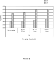
- Figure 1 shows the yield strength (Rp) of an alloy in a T6 temper solutionized via a batch-type procedure and quenched by a full water quench (referred to as "FWQ") procedure (left and center set of histograms). The alloy in T6 temper was also quenched by natural cooling in air (referred to as "Natural AQ" in Figure 1 ) (right set of histograms). Solutionizing parameters are listed below each sample set of histograms.
- Figure 2 shows yield strength (Rp) as a function of position across a width of the aluminum alloy sheet in T6 temper.
- the aluminum alloy sheet was solutionized at a temperature of 450 °C and allowed to soak for 10 minutes at 450 °C and quenched with water.
- Yield strength test samples were taken from the outer edge (left histogram, referred to as "edge"), center (right histogram, referred to as "center”) and a midpoint between the edge and center (center histogram, referred to as "quarter"). A higher yield strength was observed at the center across the width of the sheet.
- Figures 3 presents the effects of quenching on yield strength (Rp) of aluminum alloys cold rolled to a 2 mm gauge.
- Aluminum alloy sheets were solutionized and quenched via a natural air quench (AQ) (left histogram), a forced air quench (second from left histogram), a warm water quench (WQ) (water temperature 55 °C, third from left histogram) and a room temperature (RT) (e.g., between about 20 °C and 25 °C) water quench (WQ) (right histogram).
- AQ natural air quench
- WQ warm water quench
- RT room temperature
- WQ room temperature
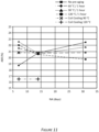
- Figures 4 and 5 show the effects of a pre-aging heat treatment (sometimes referred to as "PX") on natural age (NA) hardening of aluminum alloy sheets in T4 temper ( Figure 4 ) and T6 temper ( Figure 5 ).
- PX pre-aging heat treatment
- NA natural age
- Pre-aging was performed by heating the samples to temperatures of 60 °C (indicated by diamonds in Figures 4 and 5 ), 90 °C (indicated by triangles in Figures 4 and 5 ), or 120 °C (indicated by circles in Figures 4 and 5 ) and maintaining the temperature for 1 hour.
- Pre-aging was also performed by heating aluminum alloy sheet coils to 90 °C and allowing them to cool in air (indicated by X in Figures 4 and 5 ) or by heating aluminum alloy sheet coils to 120 °C and allowing them to cool in air to simulate natural air cooling of a production coil (indicated by + in Figures 4 and 5 ). Additionally, a control sample not subjected to pre-aging (indicated by squares in Figures 4 and 5 ) was tested. Pre-aging stabilizes the natural age hardening of the exemplary alloy.
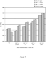
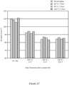
- Figures 6 and 7 show the effects of combining pre-aging and artificial aging on yield strength (Rp, Figure 6 ) and tensile strength (Rm, Figure 7 ) of alloys in T4 temper and after subjecting to heat treatment at various temperatures for various periods after two weeks of natural aging, as indicated in the figure.
- Pre-aging was performed by heating samples to temperatures of 60 °C (second from left histogram in each group), 90 °C (third from left histogram in each group), or 120 °C (right histogram in each group) and maintaining the temperature for 1 hour. Additionally, a control sample not subjected to pre-aging was tested (left histogram in each group).
- FIG. 8 Downstream processing of the comparative Sample A product (Table 8) was performed, including forming the sheets into aluminum alloy parts and coating the aluminum alloy parts.
- Figures 8 , 9 , and 10 show the effects of further processing of aluminum alloys on yield strength (Rp).
- Figure 8 shows the effect of pre-straining on aluminum alloy samples pre-aged and naturally aged (referred to as "NA") for 2 weeks. Samples were pre-strained 2 % (right histogram in each group). Additionally, a control group not subjected to pre-straining (left histogram in each group) was tested.
- Pre-aging was performed by heating samples to temperatures of 60 °C (second from left group of histograms), 90 °C (third from left group of histograms), or 120 °C (right group of histograms) and maintaining the temperature for 1 hour. Additionally, a control sample not subjected to pre-aging was tested (left group of histograms).
- Figure 9 shows the effect of paint baking on aluminum alloy samples pre-aged and naturally aged (referred to as "NA") for 2 weeks. Samples were paint baked at a temperature of 180 °C for 30 minutes (right histogram in each group). Additionally, a control group not subjected to paint baking (left histogram in each group) was tested. Pre-aging was performed by heating samples to temperatures of 60 °C (second from left group of histograms), 90 °C (third from left group of histograms), or 120 °C (right group of histograms) and maintaining the temperature for 1 hour. Additionally, a control sample not subjected to pre-aging was tested (left group of histograms).
- Figure 10 shows the effect of paint baking after pre-aging, natural aging, and artificial aging (referred to as "NA") for 2 weeks.
- Pre-aging was performed by heating samples to temperatures of 60 °C (second from left histogram in each group), 90 °C (third from left histogram in each group), or 120 °C (right histogram in each group) and maintaining the temperature for 1 hour. Additionally, a control sample not subjected to pre-aging was tested (left histogram in each group).
- Artificial aging was performed at 150 °C for 1 hour (left two groups of histograms), and to full T6 temper (right group of histograms). Paint baking was performed at 180 °C for 30 minutes.
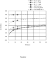
- FIG. 11 shows the effect of a pre-aging and natural aging (NA) heat treatment on formability (A80, y-axis) of aluminum alloy sheets in T4 temper.
- Pre-aging was performed by heating samples to temperatures of 60 °C (indicated by diamonds), 90 °C (indicated by triangles), or 120 °C (indicated by circles) and maintaining the temperature for 1 hour.
- Pre-aging was also performed by heating aluminum alloy sheet coils to 90 °C and allowing them to cool in air to simulate natural air cooling of a production coil (indicated by X) or by heating aluminum alloy sheet coils to 120 °C and allowing them to cool in air (indicated by +).
- Pre-aging does not significantly affect elongation of the alloy.
- a coil cooling technique e.g., by the natural air cooling of a production coil or by heating aluminum alloy sheet coils to an elevated temperature and allowing them to cool in air
- a coil cooling technique does increase yield strength and does not substantially decrease elongation.
- FIG. 12 The bendability properties of Sample A (Table 8) were assessed.
- the bendability parameters of a bendability experiment are illustrated in Figure 12 . Bendability is described in terms of angle alpha ( ⁇ ) or angle beta ( ⁇ ).
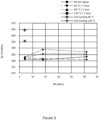
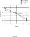
- Figure 13 shows the effects of pre-aging and natural aging (NA) on bendability (r/t) of aluminum alloys. Pre-aging was performed by heating samples to temperatures of 60 °C (indicated by diamonds), 90 °C (indicated by triangles) or 120 °C (indicated by circles) and maintaining the temperature for 1 hour. Additionally, a control sample not subjected to pre-aging (indicated by squares in Figure 13 ) was tested.
- Figure 14 shows the effects of pre-aging and natural aging (NA) on bend angle (DC alpha) of aluminum alloys.
- Pre-aging was performed by heating samples to temperatures of 60 °C (indicated by diamonds), 90 °C (indicated by triangles) or 120 °C (indicated by circles) and maintaining the temperature for 1 hour. Additionally, a control sample not subjected to pre-aging (indicated by squares in Figure 14 ) was tested. Bendability degraded with natural aging.
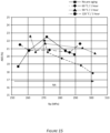
- Figures 15 and 16 show the effects of pre-aging and natural aging on formability (A80 and DC alpha) and yield strength (Rp) of aluminum alloys in T4 temper.
- Pre-aging was performed by heating samples to temperatures of 60 °C (indicated by diamonds), 90 °C (indicated by triangles) or 120 °C (indicated by circles) and maintaining the temperature for 1 hour. Additionally, a control sample not subjected to pre-aging (indicated by squares) was tested.
- Natural aging was performed by storing the alloys for 7 days (left point in each line and scatter plot), 14 days (center point in each line and scatter plot), and 31 days (right point in each line and scatter plot).
- Figure 15 shows the effects on alloy elongation (A80).
- Figure 16 shows the effects on bend angle (DC alpha).
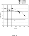
- Figure 17 shows the effects of combining pre-aging and natural aging on bend angle (DC alpha) of aluminum alloys in T4 (left grouping of histograms) and T6 temper (right three groupings of histograms).
- Pre-aging was performed by heating samples to temperatures of 60 °C (second from left histogram in each group), 90 °C (third from left histogram in each group) or 120 °C (right histogram in each group) and maintaining the temperature for 1 hour. Additionally, a control sample not subjected to pre-aging (indicated by squares) was tested (left histogram in each group).
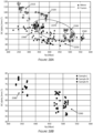
- Figure 18A is a graph showing the bendability (DC alpha, normalized to 2.0 mm (°), performed according to VDA standard 238-100) versus yield strength (Rp (MPa)) for alloys prepared and processed according to methods described above.
- Sample A in T4 temper 2310 exhibited excellent bendability and a yield strength ranging from 250 MPa to 300 MPa.
- Sample A in T6 temper 2320 exhibited excellent bendability and a yield strength ranging from 325 MPa to 400 MPa.
- Alloy 3 clad with any of Alloy 9 (Sample L), Alloy 5 (Sample M), or Alloy 8 (Sample N) in T6 temper 2330 exhibited excellent strength and bend angles ranging from 45° to 70°.
- Alloy 3 in T6 temper 2340 exhibited high strength and bend angles ranging from 45° to 55°.
- Alloy 2 in T6 temper 2350 exhibited high strength and bend angles ranging from 35° to 65°.
- Alloy 2 in T4 temper 2360 exhibited yield strengths ranging from 225 MPa to 375 MPa and bend angles ranging from 60° to 80°.
- aluminum alloys having a cladding layer (Sample A in T6 temper 2320 and Alloy 3 clad with any of Alloy 9 (Sample L), Alloy 5 (Sample M), or Alloy 8 (Sample N) in T6 temper 2330) exhibited optimal bendability and strength properties.
- the properties of Alloy 3 clad with any of Alloy 9 (Sample L), Alloy 5 (Sample M), or Alloy 8 (Sample N) in T6 temper 2330 fall within the optimal zone 2370.
- Figure 18B is a graph showing the bendability (DC alpha, normalized to 2.0 mm) versus yield strength (Rp (MPa)) for alloys prepared and processed according to methods described above.
- Samples L, M, and N (Table 11) were assessed, as detailed below.
- Samples L, M, and N in T4 temper 2380 and Samples L, M, and N in T6 temper 2390 were analyzed to show the effect of aging on the alloys.
- Samples L, M, and N in T4 temper 2380 exhibited greater bendability than Samples L, M, and N in T6 temper 2390.
- Samples L, M, and N in T6 temper 2390 exhibited greater strength than Samples L, M, and N in T4 temper 2380.
- the Alloy 5 cladding layer (data indicated by solid squares) and Alloy 8 cladding layer (data indicated by solid diamonds) improved the bendability (i.e., formability) of Alloy 3 when compared to cladding layer Alloy 9 (data indicated by solid circles).
- comparative Sample A The corrosion resistance properties of comparative Sample A were assessed, as detailed below. Corrosion testing was performed according to ASTM standard G34, Standard Test Method for Exfoliation Corrosion Susceptibility in 2xxx and 7xxx Series Aluminum Alloys (EXCO Test).
- Figure 19 shows the effect of corrosion testing on Alloy 2.
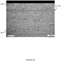
- Figure 20 is a micrograph showing the microstructure of Sample A. The sample was taken from an outer edge across a width of the aluminum alloy sheet. The outer edge sample exhibited a slightly higher degree of recrystallization near the core-clad interface 3030.
- Figure 21 shows a microstructure and the interfacial transition zones of comparative Sample A.
- Figure 21 is a micrograph taken from a sample extracted 100 m from a leading edge of Sample A.
- FIG. 22A is a cross-sectional micrograph of the weld. Five different zones, including a core 2110, a bead edge 2120, a bead center 2130, a bead root 2140, and a bead surface 2150, were evaluated for composition.
- Figure 22B is a graph showing the chemical composition in each zone.
- composition of the weld bead was homogeneous, with lower Zn and higher Mg content attributed to the Alloy 5 aluminum alloy cladding layer dissolving in a weld pool during welding.
- the reduced Zn content is indicated with a departure from a nominal Zn line (indicated by small dashes).
- FIG. 23A is a digital image showing a top view of the riveted samples.
- Figure 23B is a cross-sectional micrograph of the riveted samples.
Description
- Provided herein are novel clad aluminum alloy products. The clad alloy products are suitable for a variety of applications, including automotive and electronic applications. The clad alloy products display high strength and corrosion resistance properties.
- To reduce the weight of automobiles and meet Corporate Average Fuel Economy (CAFE) standards for carbon emissions, the automotive industry has increasingly substituted aluminum alloys for steel. Aluminum alloys, being lighter in weight, help reduce the overall automobile weight, which reduces fuel consumption. However, the introduction of aluminum alloys creates its own set of needs.
- To be useful in automobile applications, an aluminum alloy product must offer the best combination of high strength and other key attributes, such as corrosion resistance, formability, and joining ability. Among different series of aluminum alloys, 7xxx series aluminum alloys are prime candidates for high end strength applications. However, for 7xxx series alloys, an increase in strength typically results in a lowering of the aforementioned key attributes. For example, strength and corrosion resistance performance tend to be inversely related for 7xxx series alloys, meaning that while the alloys have high strength, the corrosion resistance performance is limited.
-
EP 2 581 218 A1 -
WO 2012/059505 A1 refers to an AA7000-series alloy, which may optionally be provided with a metal clad layer, such as from an AA3000-, AA4000-, AA5000-, AA6000- or a different AA7000-series aluminum alloy compared to the core. - Covered embodiments of the invention are defined by the claims, not this summary. This summary is a high-level overview of various aspects of the invention and introduces some of the concepts that are further described in the Detailed Description section below. This summary is not intended to identify key or essential features of the claimed subject matter, nor is it intended to be used in isolation to determine the scope of the claimed subject matter. The subject matter should be understood by reference to appropriate portions of the entire specification, any or all drawings, and each claim.
- Provided herein are new clad aluminum alloy-containing products. These alloy products possess a combination of strength and other key attributes, such as corrosion resistance, formability, and joining capabilities. Joining methods can include, but are not limited to, resistance spot welding (RSW), friction stir welding, remote laser welding, metal inert gas (MIG) welding, tungsten inert gas (TIG) welding, adhesive bonding, and self-piercing riveting. The alloy products can be used in a variety of applications, including automotive, transportation, electronics, and other applications.
- The clad aluminum alloy products described herein comprise a core layer comprising up to 12.0 wt. % Zn, 1.0 to 4.0 wt. % Mg, 0.1 to 3.0 wt. % Cu, up to 0.60 wt. % Si, up to 0.50 wt. % Fe, up to 0.20 wt. % Mn, up to 0.20 wt. % Cr, up to 0.30 wt. % Zr, up to 0.15 wt. % impurities, and the balance aluminum, wherein the core layer has a first side and a second side; and a first cladding layer on the first side of the core layer, wherein the first cladding layer is an AA7xxx series alloy cladding layer selected from AA7011, AA7019, AA7020, AA7021, AA7039, AA7075, AA7085, AA7108, AA7108A, AA7015, AA7017, AA7018, AA7019A, AA7024, AA7025, AA7028, AA7030, AA7031, AA7033, AA7035, AA7035A, AA7046, AA7046A, AA7003, AA7004, AA7005, AA7009, AA7010, AA7011, AA7012, AA7014, AA7016, AA7116, AA7122, AA7023, AA7026, AA7029, AA7129, AA7229, AA7032, AA7033, AA7034, AA7036, AA7136, AA7037, AA7040, AA7140, AA7041 , AA7049, AA7049A, AA7149, AA7204, AA7249, AA7349, AA7449, AA7050, AA7050A, AA7150, AA7250, AA7055, AA7155, AA7255, AA7056, AA7060, AA7064, AA7065, AA7068, AA7168, AA7175, AA7475, AA7076, AA7178, AA7278, AA7278A, AA7081, AA7181, AA7185, AA7090, AA7093, AA7095, and AA7099. Throughout this application, all elements are described in weight percentage (wt. %) based on the total weight of the alloy. In some cases, the core layer comprises 5.0 to 9.5 wt. % Zn, 1.2 to 2.3 wt. % Mg, 0.10 to 2.6 wt. % Cu, up to 0.10 wt. % Si, up to 0.15 wt. % Fe, up to 0.05 wt. % Mn, up to 0.05 wt. % Cr, up to 0.25 wt. % Zr, up to 0.15 wt. % impurities, and the balance aluminum.
- Optionally, the core layer has a thickness of about 0.5 to 3 mm (e.g., from about 0.7 to about 2.3 mm or from about 1 mm to about 2 mm). In some cases, the first cladding layer can have a thickness of about 1% to 25% of the total clad product thickness (e.g., from about 1% to about 12% of the total clad product thickness or about 10% of the total clad product thickness).
- The clad aluminum alloy product described herein can further comprise a second cladding layer located on the second side of the core layer. The first cladding layer and the second cladding layer can comprise the same or different alloys.
- Optionally, the clad aluminum alloy product has a yield strength up to 600 MPa (e.g., up to 550 MPa). The clad product can have an elongation up to 20 % (e.g., up to 15 %).
- Also provided are materials comprising the clad aluminum alloy products described herein. The materials can include automotive products (e.g., automotive structural parts), aerospace products (e.g., an aerospace structural part or an aerospace non-structural part), marine products (e.g., a marine structural part or a marine non-structural part), or electronic products (e.g., electronic device housings), among others. Further provided are aluminum sheets and plates comprising a clad aluminum alloy product as described herein.
- Other objects and advantages will be apparent from the following detailed description of non-limiting examples.
-
-
Figure 1 is a graph of tensile strength of an alloy in a T6 temper condition after various solution heat treatment and quench techniques. -
Figure 2 is a graph showing the tensile strength of an alloy in a T6 temper. Samples were taken from various lateral positions from the aluminum sheet. -
Figure 3 is a graph showing the tensile strength of an alloy of 2 mm gauge in a T6 temper after various quench techniques (e.g., a natural air quench (referred to as "AQ"), a forced AQ, a warm water quench (referred to as "WQ", water temperature of about 55 °C), and a room temperature (referred to as "RT") water quench). -
Figure 4 is a graph showing an effect of pre-aging on natural age hardening (referred to as "NA") over time of an alloy. -
Figure 5 is a graph showing an effect of pre-aging and natural aging on an alloy in a T6 temper. -
Figure 6 is a graph showing the yield strengths of alloys after various heat treatments. -
Figure 7 is a graph showing the tensile strengths of alloys after various heat treatments. -
Figure 8 is a graph showing the yield strengths of alloys after a pre-straining and heat treatment procedure. -
Figure 9 is a graph showing the yield strengths of alloys after a paint bake procedure. -
Figure 10 is a graph showing the yield strengths of alloys after a heat treatment and paint bake procedure. -
Figure 11 is a graph showing the elongations of alloys after natural aging. -
Figure 12 is a schematic depicting bend test analysis. -
Figure 13 is a graph showing the R/t ratios (f-factor) of alloys after pre-aging and natural aging. -
Figure 14 is a graph showing the bend angle (DC alpha, normalized to 2.0 mm (°)) of alloys after pre-aging and natural aging. Samples were evaluated after 7 days (left point), 14 days (second from left point), 60 days (third from left point), and 90 days (right point) of natural aging. -
Figure 15 is a graph showing the elongations (A80) of alloys as a function of yield strength (Rp) after various pre-aging and natural aging. Samples were evaluated after 7 days (left point), 14 days (second from left point), 31 days (center point), 60 days (second from right point), and 90 days (right point) of natural aging. -
Figure 16 is a graph showing bend angle (DC alpha, normalized to 2.0 mm (°)) of alloys as a function of yield strength (Rp) after various pre-aging and natural aging. Samples were evaluated after 7 days (left point), 14 days (second from left point), 60 days (third from left point), and 90 days (right point) of natural aging. -
Figure 17 is a graph showing the bend angles (DC alpha, normalized to 2.0 mm (°)) of alloys after pre-aging and artificial aging procedures. -
Figure 18A is a graph showing the bendability (DC alpha, normalized to 2.0 mm (°)) and yield strengths (Rp (MPa)) for alloys prepared and processed according to methods described herein. -
Figure 18B is a graph showing the bendability (DC alpha, normalized to 2.0 mm (°)) and yield strengths (Rp (MPa)) for alloys prepared and processed according to methods described herein. -
Figure 19 is a digital image showing corrosion on a comparative non-clad aluminum alloy sample (i.e., a monolithic 7xxx series aluminum alloy without a 5xxx clad layer). -
Figure 20 is a micrograph showing microstructure of an comparative clad aluminum alloy sample (i.e., a 7xxx series aluminum alloy core layer with a 5xxx clad layer) in a T4 temper. -
Figure 21 is a micrograph showing microstructure of an comparative clad aluminum alloy sample (i.e., a 7xxx series aluminum alloy core layer with a 5xxx clad layer) in a T4 temper. -
Figure 22A is a micrograph image showing a partial penetration weld of an comparative clad aluminum alloy sample having a 7xxx series aluminum alloy core layer with a 5xxx clad layer in a T6 temper. -
Figure 22B is a graph showing the zinc, magnesium, and copper content from various areas of a partial penetration weld. -
Figure 23A is a digital image showing riveted comparative clad aluminum alloy samples having a 7xxx series aluminum alloy core layer with a 5xxx clad layer in F, T4, and T6 tempers. -
Figure 23B is a micrograph image showing a cross section of the riveted clad aluminum alloy samples. - Described herein are new clad aluminum alloy products. The clad aluminum alloy products include a core layer and one or more cladding layers. For cladded aluminum alloy products, the core layer, which represents the largest component of the material, mainly determines the bulk mechanical properties of the cladded material (e.g., strength). On the other hand, the cladding layer(s), which represents a small component of the material, is in contact with the environment surrounding the cladded material and thus determines the chemical activity (e.g., corrosion resistance) and can affect the formability and joining properties of the cladded material.
- The clad aluminum alloy products described herein possess a combination of strength and other key attributes, such as corrosion resistance, formability, and joining capabilities. Joining methods can include, but are not limited to, resistance spot welding (RSW), friction stir welding (FSW), remote laser welding, metal inert gas (MIG) welding, tungsten inert gas (TIG) welding, adhesive bonding, and self-piercing riveting.
- As used herein, the terms "invention," "the invention," "this invention," and "the present invention" are intended to refer broadly to all of the subject matter of this patent application and the claims below. Statements containing these terms should be understood not to limit the subject matter described herein or to limit the meaning or scope of the patent claims below.
- In this description, reference is made to alloys identified by AA numbers and other related designations, such as "series" or "7xxx." For an understanding of the number designation system most commonly used in naming and identifying aluminum and its alloys, see "International Alloy Designations and Chemical Composition Limits for Wrought Aluminum and Wrought Aluminum Alloys" or "Registration Record of Aluminum Association Alloy Designations and Chemical Compositions Limits for Aluminum Alloys in the Form of Castings and Ingot," both published by The Aluminum Association.
- As used herein, a plate generally has a thickness of greater than 15 mm. For example, a plate may refer to an aluminum product having a thickness of greater than 15 mm, greater than 20 mm, greater than 25 mm, greater than 30 mm, greater than 35 mm, greater than 40 mm, greater than 45 mm, greater than 50 mm, or greater than 100 mm.
- As used herein, a shate (also referred to as a sheet plate) generally has a thickness of from 4 mm to 15 mm. For example, a shate may have a thickness of 4 mm, 5 mm, 6 mm, 7 mm, 8 mm, 9 mm, 10 mm, 11 mm, 12 mm, 13 mm, 14 mm, or 15 mm.
- As used herein, a sheet generally refers to an aluminum product having a thickness of less than 4 mm. For example, a sheet may have a thickness of less than 4 mm, less than 3 mm, less than 2 mm, less than 1 mm, less than 0.5 mm, less than 0.3 mm, or less than 0.1 mm.
- Reference is made in this application to alloy temper or condition. For an understanding of the alloy temper descriptions most commonly used, see "American National Standards (ANSI) H35 on Alloy and Temper Designation Systems." An F condition or temper refers to an aluminum alloy as fabricated. An O condition or temper refers to an aluminum alloy after annealing. A T4 condition or temper refers to an aluminum alloy after solution heat treatment (i.e., solutionization) followed by natural aging. A T6 condition or temper refers to an aluminum alloy after solution heat treatment followed by artificial aging. A T8x condition or temper refers to an aluminum alloy solution heat treated, cold worked, and artificially aged.
- As used herein, terms such as "cast metal product," "cast product," "cast aluminum alloy product," and the like are interchangeable and refer to a product produced by direct chill casting (including direct chill co-casting) or semi-continuous casting, continuous casting (including, for example, by use of a twin belt caster, a twin roll caster, a block caster, or any other continuous caster), electromagnetic casting, hot top casting, or any other casting method.
- As used herein, the meaning of "room temperature" can include a temperature of from 15 °C to 30 °C, for example 15 °C, 16 °C, 17 °C, 18 °C, 19 °C, 20 °C, 21 °C, 22 °C, 23 °C, 24 °C, 25 °C, 26 °C, 27 °C, 28 °C, 29 °C, or 30 °C. As used herein, the meaning of "ambient conditions" can include temperatures of room temperature, relative humidity of from 20 % to 100 %, and barometric pressure of from 975 millibar (mbar) to 1050 mbar. For example, relative humidity can be 20 %, 21 %, 22 %, 23 %, 24 %, 25 %, 26 %, 27 %, 28 %, 29 %, 30 %, 31 %, 32 %, 33 %, 34 %, 35 %, 36 %, 37 %, 38 %, 39 %, 40 %, 41 %, 42 %, 43 %, 44 %, 45 %, 46 %, 47 %, 48 %, 49 %, 50 %, 51 %, 52 %, 53 %, 54%, 55 %, 56 %, 57 %, 58 %, 59 %, 60 %, 61 %, 62 %, 63 %, 64 %, 65 %, 66 %, 67 %, 68 %, 69 %, 70 %, 71 %, 72 %, 73 %, 74 %, 75 %, 76 %, 77 %, 78 %, 79 %, 80 %, 81 %, 82%, 83 %, 84 %, 85 %, 86 %, 87 %, 88 %, 89 %, 90 %, 91 %, 92 %, 93 %, 94 %, 95 %, 96 %, 97 %, 98 %, 99 %, 100 %, or anywhere in between. For example, barometric pressure can be 975 mbar, 980 mbar, 985 mbar, 990 mbar, 995 mbar, 1000 mbar, 1005 mbar, 1010 mbar, 1015 mbar, 1020 mbar, 1025 mbar, 1030 mbar, 1035 mbar, 1040 mbar, 1045 mbar, 1050 mbar, or anywhere in between.
- All ranges disclosed herein are to be understood to encompass any and all subranges subsumed therein. For example, a stated range of "1 to 10" should be considered to include any and all subranges between (and inclusive of) the minimum value of 1 and the maximum value of 10; that is, all subranges beginning with a minimum value of 1 or more, e.g. 1 to 6.1, and ending with a maximum value of 10 or less, e.g., 5.5 to 10.
- As used herein, the meaning of "a," "an," and "the" includes singular and plural references unless the context clearly dictates otherwise.
- In the following examples, the aluminum alloy products and their components are described in terms of their elemental composition in weight percent (wt. %). In each alloy, the remainder is aluminum, with a maximum wt. % of 0.15 % for the sum of all impurities.
- Provided herein are new clad aluminum alloy products. The clad aluminum alloy products include a core layer of an aluminum alloy having a first side and a second side and one or more cladding layer(s) bonded to the first side or the second side of the core layer. In some examples, the core layer is clad on only one side (i.e., one cladding layer is present in the clad aluminum alloy product). In other examples, the core layer is clad on both sides (i.e., two cladding layers are present in the clad aluminum alloy product).
- The first side of the core layer is adjacent to and contacts a first cladding layer to form a first interface. In other words, no layers intervene between the first cladding layer and the first side of the core layer. Optionally, the clad aluminum alloy product includes a second cladding layer. In these instances, the second side of the core layer is adjacent to and contacts a second cladding layer to form a second interface (i.e., no layers intervene between the second cladding layer and the second side of the core layer). The first cladding layer and the second cladding layer can be the same chemical composition or different chemical compositions.
- The core layer is an aluminum-containing alloy. The alloy for use as the core layer has the following elemental composition as provided in Table 1.
Table 1 Element Weight Percentage (wt. %) Zn Up to 12.0 Mg 1.0 - 4.0 Cu 0.1 - 3.0 Si Up to 0.60 Fe Up to 0.50 Mn Up to 0.20 Cr Up to 0.20 Zr Up to 0.30 Impurities Up to 0.15 Al Remainder - In some examples, the alloy for use as the core layer can have the following elemental composition as provided in Table 2.
Table 2 Element Weight Percentage (wt. %) Zn 5.0 to 9.5 Mg 1.2 - 2.3 Cu 0.1 - 2.6 Si Up to 0.10 Fe Up to 0.15 Mn Up to 0.05 Cr Up to 0.05 Zr Up to 0.25 Impurities Up to 0.15 Al Remainder - The alloy described herein for use as the core layer includes zinc (Zn) in an amount of up to 12.0 % (e.g., from 0.5 % to 12.0 %, from 5.0 % to 12.0 %, from 5.0 % to 9.5 %, or from 5.0 % to 8.4 %) based on the total weight of the alloy. For example, the alloy can include 0.1 %, 0.2 %, 0.3 %, 0.4 %, 0.5 %, 0.6 %, 0.7 %, 0.8 %, 0.9 %, 1.0 %, 1.1 %, 1.2 %, 1.3 %, 1.4 %, 1.5 %, 1.6 %, 1.7 %, 1.8 %, 1.9 %, 2.0 %, 2.1 %, 2.2 %, 2.3 %, 2.4 %, 2.5 %, 2.6 %, 2.7 %, 2.8 %, 2.9 %, 3.0 %, 3.1 %, 3.2 %, 3.3 %, 3.4 %, 3.5 %, 3.6 %, 3.7 %, 3.8 %, 3.9 %, 4.0 %, 4.1 %, 4.2 %, 4.3 %, 4.4 %, 4.5 %, 4.6 %, 4.7 %, 4.8 %, 4.9 %, 5.0 %, 5.1 %, 5.2 %, 5.3 %, 5.4 %, 5.5 %, 5.6 %, 5.7 %, 5.8 %, 5.9 %, 6.0 %, 6.1 %, 6.2 %, 6.3 %, 6.4 %, 6.5 %, 6.6 %, 6.7 %, 6.8 %, 6.9 %, 7.0 %, 7.1 %, 7.2 %, 7.3 %, 7.4 %, 7.5 %, 7.6 %, 7.7 %, 7.8 %, 7.9 %, 8.0 %, 8.1 %, 8.2 %, 8.3 %, 8.4 %, 8.5 %, 8.6 %, 8.7 %, 8.8 %, 8.9 %, 9.0 %, 9.1 %, 9.2 %, 9.3 %, 9.4 %, 9.5 % Zn, 9.6 %, 9.7 %, 9.8 %, 9.9 %, 10.0 %, 10.1 %, 10.2 %, 10.3 %, 10.4 %, 10.5 %, 10.6 %, 10.7 %, 10.8 %, 10.9 %, 11.0 %, 11.1 %, 11.2 %, 11.3 %, 11.4 %, 11.5 %, 11.6 %, 11.7 %, 11.8 %, 11.9 %, or 12.0 %. In some cases, Zn is not present in the alloy (i.e., 0 %). All expressed in wt. %.
- The alloy described herein for use as the core layer also includes magnesium (Mg) in an amount of from 1.0 % to 4.0 % (e.g., from 1.0 % to 3.7 %, from 1.1 % to 2.6 %, from 1.2 % to 2.3 %, or from 1.5 % to 2.0 %) based on the total weight of the alloy. For example, the alloy can include 1.0 %, 1.1 %, 1.2 %, 1.3 %, 1.4 %, 1.5 %, 1.6 %, 1.7 %, 1.8 %, 1.9 %, 2.0 %, 2.1 %, 2.2 %, 2.3 %, 2.4 %, 2.5 %, 2.6 %, 2.7 %, 2.8 %, 2.9 %, 3.0 %, 3.1 %, 3.2 %, 3.3 %, 3.4 %, 3.5 %, 3.6 %, 3.7 %, 3.8 %, 3.9 %, or 4.0 % Mg. All expressed in wt. %.
- The alloy described herein for use as the core layer also includes copper (Cu) in an amount of from 0.1 % to 3.0 % (e.g., from 0.1 % to 2.6 % or from 0.15 % to 2.0 %) based on the total weight of the alloy. For example, the alloy can include 0.1 %, 0.2 %, 0.3 %, 0.4 %, 0.5 %, 0.6 %, 0.7 %, 0.8 %, 0.9 %, 1.0 %, 1.1 %, 1.2 %, 1.3 %, 1.4 %, 1.5 %, 1.6 %, 1.7 %, 1.8 %, 1.9 %, 2.0 %, 2.1 %, 2.2 %, 2.3 %, 2.4 %, 2.5 %, 2.6 %, 2.7 %, 2.8 %, 2.9 %, or 3.0 % Cu. All expressed in wt. %.
- The alloy described herein for use as the core layer can also include silicon (Si) in an amount of up to 0.60 % (e.g., from 0 % to 0.4 %, from 0.05 % to 0.2 %, or 0.1 %) based on the total weight of the alloy. For example, the alloy can include 0.01 %, 0.02 %, 0.03 %, 0.04 %, 0.05 %, 0.06 %, 0.07 %, 0.08 %, 0.09 %, 0.1 %, 0.11 %, 0.12 %, 0.13 %, 0.14 %, 0.15 %, 0.16 %, 0.17 %, 0.18 %, 0.19 %, 0.2 %, 0.21 %, 0.22 %, 0.23 %, 0.24 %, 0.25 %, 0.26 %, 0.27 %, 0.28 %, 0.29 %, 0.3 %, 0.31 %, 0.32 %, 0.33 %, 0.34 %, 0.35 %, 0.36 %, 0.37 %, 0.38 %, 0.39 %, 0.4 %, 0.41 %, 0.42 %, 0.43 %, 0.44 %, 0.45 %, 0.46 %, 0.47 %, 0.48 %, 0.49 %, 0.5 %, 0.51 %, 0.52 %, 0.53 %, 0.54 %, 0.55 %, 0.56 %, 0.57 %, 0.58 %, 0.59 %, or 0.60 % Si. In some cases, Si is not present in the alloy (i.e., 0 %). All expressed in wt. %.
- The alloy described herein for use as the core layer can also include iron (Fe) in an amount of up to 0.50 % (e.g., from 0 % to 0.25 % or from 0.05 % to 0.15 %) based on the total weight of the alloy. For example, the alloy can include 0.01 %, 0.02 %, 0.03 %, 0.04 %, 0.05 %, 0.06 %, 0.07 %, 0.08 %, 0.09 %, 0.10 %, 0.11 %, 0.12 %, 0.13 %, 0.14 %, 0.15 %, 0.16 %, 0.17 %, 0.18 %, 0.19 %, 0.20 %, 0.21 %, 0.22 %, 0.23 %, 0.24 %, 0.25 %, 0.26 %, 0.27 %, 0.28 %, 0.29 %, 0.3 %, 0.31 %, 0.32 %, 0.33 %, 0.34 %, 0.35 %, 0.36 %, 0.37 %, 0.38 %, 0.39 %, 0.4 %, 0.41 %, 0.42 %, 0.43 %, 0.44 %, 0.45 %, 0.46 %, 0.47 %, 0.48 %, 0.49 %, or 0.50 % Fe. In some cases, Fe is not present in the alloy (i.e., 0 %). All expressed in wt. %.
- The alloy described herein for use as the core layer can also include manganese (Mn) in an amount of up to 0.20 % (e.g., from 0 % to 0.10 %, from 0.01 % to 0.05 %, or from 0.02 % to 0.10 %) based on the total weight of the alloy. For example, the alloy can include 0.01 %, 0.02 %, 0.03 %, 0.04 %, 0.05 %, 0.06 %, 0.07 %, 0.08 %, 0.09 %, 0.1 %, 0.11 %, 0.12 %, 0.13 %, 0.14 %, 0.15 %, 0.16 %, 0.17 %, 0.18 %, 0.19 %, or 0.20 % Mn. In some cases, Mn is not present in the alloy (i.e., 0 %). All expressed in wt. %.
- The alloy described herein for use as the core layer can also include chromium (Cr) in an amount of up to 0.20 % (e.g., from 0 % to 0.10 %, from 0.01 % to 0.05 %, or from 0.02 % to 0.10 %) based on the total weight of the alloy. For example, the alloy can include 0.01 %, 0.02 %, 0.03 %, 0.04 %, 0.05 %, 0.06 %, 0.07 %, 0.08 %, 0.09 %, 0.1 %, 0.11 %, 0.12 %, 0.13 %, 0.14 %, 0.15 %, 0.16 %, 0.17 %, 0.18 %, 0.19 %, or 0.20 % Cr. In some cases, Cr is not present in the alloy (i.e., 0 %). All expressed in wt. %.
- The alloy described herein for use as the core layer can also include zirconium (Zr) in an amount of up to 0.30 % (e.g., from 0 % to 0.25 % or from 0.05 % to 0.20 %) based on the total weight of the alloy. For example, the alloy can include 0.01 %, 0.02 %, 0.03 %, 0.04 %, 0.05 %, 0.06 %, 0.07 %, 0.08 %, 0.09 %, 0.10 %, 0.11 %, 0.12 %, 0.13 %, 0.14 %, 0.15 %, 0.16 %, 0.17 %, 0.18 %, 0.19 %, 0.20 %, 0.21 %, 0.22 %, 0.23 %, 0.24 %, 0.25 %, 0.26 %, 0.27 %, 0.28 %, 0.29 %, or 0.30 % Zr. In some cases, Zr is not present in the alloy (i.e., 0 %). All expressed in wt. %.
- Optionally, the alloy composition described herein for use as the core layer can further include other minor elements, sometimes referred to as impurities, in amounts of 0.05% or below, 0.04% or below, 0.03% or below, 0.02% or below, or 0.01% or below each. These impurities may include, but are not limited to, V, Ni, Sn, Ga, Ca, Bi, Na, Pb, or combinations thereof. Accordingly, V, Ni, Sn, Ga, Ca, Bi, Na, or Pb may be present in alloys in amounts of 0.05% or below, 0.04% or below, 0.03% or below, 0.02% or below, or 0.01% or below. The sum of all impurities does not exceed 0.15% (e.g., 0.10%). All expressed in wt. %. The remaining percentage of the alloy is aluminum.
- In some examples, any alloy designated as an "AA7xxx series" alloy is suitable for use as the core layer. By way of non-limiting example, the AA7xxx series alloys suitable for use as the core layer can include AA7021, AA7075, AA7055, AA7085, AA7011, AA7019, AA7020, AA7039, AA7072, AA7108, AA7108A, AA7015, AA7017, AA7018, AA7019A, AA7024, AA7025, AA7028, AA7030, AA7031, AA7033, AA7035, AA7035A, AA7046, AA7046A, AA7003, AA7004, AA7005, AA7009, AA7010, AA7011, AA7012, AA7014, AA7016, AA7116, AA7122, AA7023, AA7026, AA7029, AA7129, AA7229, AA7032, AA7033, AA7034, AA7036, AA7136, AA7037, AA7040, AA7140, AA7041 , AA7049, AA7049A, AA7149, AA7204, AA7249, AA7349, AA7449, AA7050, AA7050A, AA7150, AA7250, AA7155, AA7255, AA7056, AA7060, AA7064, AA7065, AA7068, AA7168, AA7175, AA7475, AA7076, AA7178, AA7278, AA7278A, AA7081, AA7181, AA7185, AA7090, AA7093, AA7095, and AA7099.
- The thickness of the core layer can be from 50 % to 99 % of the clad aluminum alloy products described herein. For example, in a clad aluminum alloy product having a thickness of 1000 microns, the core layer can have a thickness of 500 microns to 990 microns. Optionally, the core layer can have a thickness in the range of about 0.5 mm to about 3 mm (e.g., from about 0.7 mm to about 2.3 mm). For example, the thickness of the core layer can be 0.5 mm, 0.6 mm, 0.7 mm, 0.8 mm, 0.9 mm, 1.0 mm, 1.1 mm, 1.2 mm, 1.3 mm, 1.4 mm, 1.5 mm, 1.6 mm, 1.7 mm, 1.8 mm, 1.9 mm, 2.0 mm, 2.1 mm, 2.2 mm, 2.3 mm, 2.4 mm, 2.5 mm, 2.6 mm, 2.7 mm, 2.8 mm, 2.9 mm, or 3.0 mm.
- Also described herein is an aluminum-containing alloy for use as the cladding layer(s) in the clad aluminum alloy products. Any alloy designated as an "AA7xxx series" alloy is suitable for use as the cladding layer.
- The AA7xxx series alloy for use as the cladding layer is selected from AA7011, AA7019, AA7020, AA7021, AA7039, AA7075, AA7085, AA7108, AA7108A, AA7015, AA7017, AA7018, AA7019A, AA7024, AA7025, AA7028, AA7030, AA7031, AA7033, AA7035, AA7035A, AA7046, AA7046A, AA7003, AA7004, AA7005, AA7009, AA7010, AA7011, AA7012, AA7014, AA7016, AA7116, AA7122, AA7023, AA7026, AA7029, AA7129, AA7229, AA7032, AA7033, AA7034, AA7036, AA7136, AA7037, AA7040, AA7140, AA7041 , AA7049, AA7049A, AA7149, AA7204, AA7249, AA7349, AA7449, AA7050, AA7050A, AA7150, AA7250, AA7055, AA7155, AA7255, AA7056, AA7060, AA7064, AA7065, AA7068, AA7168, AA7175, AA7475, AA7076, AA7178, AA7278, AA7278A, AA7081, AA7181, AA7185, AA7090, AA7093, AA7095, and AA7099.
- Clad layers as described herein can improve surface corrosion resistance properties of the products, improve pretreatment efficiency, aid bending, riveting hole piercing and clinching, and can make the alloy product usable in T4 temper for some parts without hot forming. Moreover, when a filler wire alloy, such as AA7021, is used as the clad layer, laser welding can be accomplished without using filler wire.
- The thickness of each cladding layer can be from about 1 % to about 25 % of the total thickness of the clad aluminum alloy products described herein (e.g., from about 1 % to about 12 %, or about 10 %). For example, in an aluminum alloy product having a thickness of 1000 microns, each cladding layer can have a thickness of 10 microns to 250 microns. Optionally, each cladding layer can have a thickness in the range of 0.20 mm to 0.80 mm.
- As described above, the clad aluminum alloy products can contain one cladding layer or more than one cladding layer. In some cases, the clad aluminum alloy products contain only a first cladding layer. In some cases, the clad aluminum alloy products contain a first cladding layer and a second cladding layer. In some cases, the first cladding layer and the second cladding layer are identical in composition. In other cases, the first cladding layer and the second cladding layer differ in composition. The resulting clad aluminum alloy products exhibit excellent balanced properties, such as strength, formability, corrosion resistance, dent resistance, and hemming performance.
- The alloys described herein for use as the core and cladding layers can be cast using any suitable casting method. As a few non-limiting examples, the casting process can include a direct chill (DC) casting process or a continuous casting (CC) process.
- A clad layer as described herein can be attached to a core layer as described herein to form a cladded product by any means known to persons of ordinary skill in the art. For example, a clad layer can be attached to a core layer by direct chill co-casting (i.e., fusion casting) as described in, for example,
U.S. Patent Nos. 7,748,434 and8,927,113 , by hot and cold rolling a composite cast ingot as described inU.S. Patent No. 7,472,740 , or by roll bonding to achieve the required metallurgical bonding between the core and the cladding; or by other methods as known to persons of ordinary skill in the art. The initial dimensions and final dimensions of the clad aluminum alloy products described herein can be determined by the desired properties of the overall final product. - The roll bonding process can be carried out in different manners, as known to those of ordinary skill in the art. For example, the roll-bonding process can include both hot rolling and cold rolling. Further, the roll bonding process can be a one-step process or a multi-step process in which the material is gauged down during successive rolling steps. Separate rolling steps can optionally be separated by other processing steps, including, for example, annealing steps, cleaning steps, heating steps, cooling steps, and the like.
- The co-cast ingot or other cast product can be processed by any means known to those of ordinary skill in the art. Optionally, the processing steps can be used to prepare sheets. Such processing steps include, but are not limited to, homogenization, hot rolling, cold rolling, solution heat treatment, and an optional pre-aging step, as known to those of ordinary skill in the art.
- In the homogenization step of a DC casting process, the co-cast ingot described herein is heated to a temperature ranging from 400 °C to 500 °C. For example, the ingot can be heated to a temperature of 400 °C, 410 °C, 420 °C, 430 °C, 440 °C, 450 °C, 460 °C, 470 °C, 480°C, 490 °C, or 500 °C. The ingot is then allowed to soak (i.e., held at the indicated temperature) for a period of time. In some examples, the total time for the homogenization step, including the heating and soaking phases, can be up to 24 hours. For example, the ingot can be heated up to 500 °C and soaked, for a total time of up to 18 hours for the homogenization step. Optionally, the ingot can be heated to below 490 °C and soaked, for a total time of greater than 18 hours for the homogenization step. In some cases, the homogenization step comprises multiple processes. In some non-limiting examples, the homogenization step includes heating the ingot to a first temperature for a first period of time followed by heating to a second temperature for a second period of time. For example, the ingot can be heated to 465 °C for 3.5 hours and then heated to 480 °C for 6 hours.
- Following the homogenization step of the co-cast ingot, a hot rolling step can be performed. Prior to the start of hot rolling, the homogenized ingot can be allowed to cool to a temperature of from 300 °C to 450 °C. For example, the homogenized ingot can be allowed to cool to a temperature of from 325 °C to 425 °C or from 350 °C to 400 °C. The ingots can then be hot rolled at a temperature between 300 °C to 450 °C to form a hot rolled plate, a hot rolled shate or a hot rolled sheet having a gauge of from 3 mm to 200 mm (e.g., 3 mm, 4 mm, 5 mm, 6 mm, 7 mm, 8 mm, 9 mm, 10 mm, 15 mm, 20 mm, 25 mm, 30 mm, 35 mm, 40 mm, 45 mm, 50 mm, 55 mm, 60 mm, 65 mm, 70 mm, 75 mm, 80 mm, 85 mm, 90 mm, 95 mm, 100 mm, 110 mm, 120 mm, 130 mm, 140 mm, 150 mm, 160 mm, 170 mm, 180 mm, 190 mm, 200 mm, or anywhere in between). Optionally, the cast product can be a continuously cast product that can be allowed to cool to a temperature of from 300 °C to 450 °C. For example, the continuously cast product can be allowed to cool to a temperature of from 325 °C to 425 °C or from 350 °C to 400 °C. The continuously cast product can then be hot rolled at a temperature of from 300 °C to 450 °C to form a hot rolled plate, a hot rolled shate or a hot rolled sheet having a gauge of from 3 mm to 200 mm (e.g., 3 mm, 4 mm, 5 mm, 6 mm, 7 mm, 8 mm, 9 mm, 10 mm, 15 mm, 20 mm, 25 mm, 30 mm, 35 mm, 40 mm, 45 mm, 50 mm, 55 mm, 60 mm, 65 mm, 70 mm, 75 mm, 80 mm, 85 mm, 90 mm, 95 mm, 100 mm, 110 mm, 120 mm, 130 mm, 140 mm, 150 mm, 160 mm, 170 mm, 180 mm, 190 mm, 200 mm, or anywhere in between). During hot rolling, temperatures and other operating parameters can be controlled so that the temperature of the clad alloy hot rolled product upon exit from the hot rolling mill is no more than 470 °C, no more than 450 °C, no more than 440 °C, or no more than 430 °C.
- The clad plate, shate, or sheet can then be cold rolled using conventional cold rolling mills and technology. The cold rolled clad sheet can have a gauge of from 0.5 mm to 10 mm, e.g., between 0.7 mm to 6.5 mm. Optionally, the cold rolled clad sheet can have a gauge of 0.5 mm, 1.0 mm, 1.5 mm, 2.0 mm, 2.5 mm, 3.0 mm, 3.5 mm, 4.0 mm, 4.5 mm, 5.0 mm, 5.5 mm, 6.0 mm, 6.5 mm, 7.0 mm, 7.5 mm, 8.0 mm, 8.5 mm, 9.0 mm, 9.5 mm, or 10.0 mm. The cold rolling can be performed to result in a final gauge thickness that represents a gauge reduction of up to 85 % (e.g., up to 10 %, up to 20 %, up to 30 %, up to 40 %, up to 50 %, up to 60 %, up to 70 %, up to 80 %, or up to 85 % reduction). Optionally, an interannealing step can be performed during the cold rolling step. The interannealing step can be performed at a temperature of from 300 °C to 450 °C (e.g., 310 °C, 320 °C, 330 °C, 340 °C, 350 °C, 360 °C, 370 °C, 380 °C, 390 °C, 400 °C, 410 °C, 420 °C, 430 °C, 440 °C, or 450 °C). In some cases, the interannealing step comprises multiple processes. In some non-limiting examples, the interannealing step includes heating the clad plate, shate, or sheet to a first temperature for a first period of time followed by heating to a second temperature for a second period of time. For example, the clad plate, shate, or sheet can be heated to 410 °C for 1 hour and then heated to 330 °C for 2 hours.
- Subsequently, the clad plate, shate, or sheet can undergo a solution heat treatment step. The solution heat treatment step can include any conventional treatment for the clad sheet which results in solutionizing of the soluble particles. The clad plate, shate, or sheet can be heated to a peak metal temperature (PMT) of up to 590 °C (e.g., from 400 °C to 590 °C) and soaked for a period of time at the temperature. For example, the clad plate, shate or sheet can be soaked at 480 °C for a soak time of up to 30 minutes (e.g., 0 seconds, 60 seconds, 75 seconds, 90 seconds, 5 minutes, 10 minutes, 20 minutes, 25 minutes, or 30 minutes). After heating and soaking, the clad plate, shate, or sheet is rapidly cooled at rates greater than 50 °C/second (°C/s) to a temperature from 500 °C to 200 °C. In one example, the clad plate, shate or sheet has a quench rate of above 200 °C/s at temperatures from 450 °C to 200 °C. Optionally, the cooling rates can be faster in other cases.
- After quenching, the clad plate, shate or sheet can optionally undergo a pre-aging treatment by reheating the plate, shate, or sheet before coiling. The pre-aging treatment can be performed at a temperature of from 50 °C to 150 °C for a period of time of up to 6 hours. For example, the pre-aging treatment can be performed at a temperature of 50 °C, 55 °C, 60 °C, 65 °C, 70 °C, 75 °C, 80 °C, 85 °C, 90 °C, 95 °C, 100 °C, 105 °C, 110 °C, 115 °C, 120 °C, 125 °C, 130 °C, 135 °C, 140 °C, 145 °C, or 150 °C. Optionally, the pre-aging treatment can be performed for 30 minutes, 1 hour, 2 hours, 3 hours, 4 hours, 5 hours, or 6 hours. The pre-aging treatment can be carried out by passing the plate, shate, or sheet through a heating device, such as a device that emits radiant heat, convective heat, induction heat, infrared heat, or the like.
- The co-cast ingots or other co-cast products described herein can also be used to make products in the form of plates or other suitable products. The products can be made using techniques as known to those of ordinary skill in the art. For example, plates including the clad products as described herein can be prepared by processing a co-cast ingot in a homogenization step or casting a co-cast product in a continuous caster followed by a hot rolling step. In the hot rolling step, the cast product can be hot rolled to a 200 mm thick gauge or less (e.g., from 10 mm to 200 mm). For example, the cast product can be hot rolled to a plate having a final gauge thickness of 10 mm to 175 mm, 15 mm to 150 mm, 20 mm to 125 mm, 25 mm to 100 mm, 30 mm to 75 mm, or 35 mm to 50 mm.
- The clad aluminum alloy products described herein can be designed to achieve any desired strength level as determined by persons of ordinary skill in the art. For example, the clad aluminum alloy products described herein can have yield strengths of up to 600 MPa (e.g., from 400 MPa to 600 MPa, from 450 MPa to 600 MPa, or from 500 MPa to 600 MPa). In some examples, the yield strengths of the products can be 400 MPa, 425 MPa, 450 MPa, 475 MPa, 500 MPa, 525 MPa, 550 MPa, 575 MPa, or 600 MPa.
- In addition, the clad aluminum alloy products described herein can have elongations of up to 20%. For example, the elongations can be 10 %, 11 %, 12 %, 13 %, 14 %, 15 %, 16 %, 17 %, 18%, 19%, or 20%.
- Further, the clad aluminum alloy products described herein can have strong bendability properties. A bend angle of from 45° to 120° can be achieved, based on the desired use of the product, as measured by a three-point bend test according to VDA Standard 238-100, normalized to 2.0 mm. For example, the clad aluminum products described herein can achieve a bend angle of 45°, 50°, 55°, 60°, 65°, 70°, 75°, 80°, 85°, 90°, 95°, 100°, 105°, 110°, 115°, or 120°.
- In some examples, a clad aluminum alloy sheet made according to a method described herein can have a minimum R/t ratio (i.e., f-factor) of 1.2 without cracking. The R/t ratio can provide an assessment of the bendability of a material. As described below, the bendability is assessed based on the R/t ratio, where R is the radius of the tool (die) used and t is the thickness of the material. A lower R/t ratio indicates better bendability of the material. The R/t ratio of the aluminum alloys described herein can be 1.1 or lower (e.g., 1.0 or lower, 0.9 or lower, 0.8 or lower, or 0.7 or lower).
- The clad aluminum alloy products described herein can be used in automotive applications and other transportation applications, including aircraft and railway applications. For example, the clad aluminum alloy products can be used to prepare automotive structural parts, such as bumpers, side beams, roof beams, cross beams, pillar reinforcements (e.g., A-pillars, B-pillars, and C-pillars), inner panels, outer panels, side panels, inner hoods, outer hoods, or trunk lid panels. The clad aluminum alloy products and methods described herein can also be used in aircraft or railway vehicle applications, to prepare, for example, external and internal panels. In some examples, the clad aluminum alloy products can be used in aerospace structural and non-structural parts or in marine structural or non-structural parts.
- The clad aluminum alloy products and methods described herein can also be used in electronics applications. For example, the clad aluminum alloy products and methods described herein can be used to prepare housings for electronic devices, including mobile phones and tablet computers. In some examples, the clad aluminum alloy products can be used to prepare housings for the outer casings of mobile phones (e.g., smart phones) and tablet bottom chassis.
- The clad aluminum alloy products and methods described herein can also be used in other applications as desired. The clad aluminum alloy products described herein can be provided as clad aluminum alloy sheets and/or clad aluminum alloy plates suitable for further processing by an end user. For example, a clad aluminum alloy sheet can be further subjected to surface treatments by an end user for use as an architectural skin panel for aesthetic and structural purposes.
- The following examples will serve to further illustrate the present invention without, at the same time, however, constituting any limitation thereof. On the contrary, it is to be clearly understood that resort may be had to various embodiments, and modifications thereof which, after reading the description herein, may suggest themselves to those skilled in the art without departing from the invention as defined by the claims. During the studies described in the following examples, conventional procedures were followed, unless otherwise stated. Some of the procedures are described below for illustrative purposes.
- Clad aluminum alloy products were produced by preparing a co-cast ingot including an AA7xxx series core that was clad on both sides, homogenizing at 465 °C for 3.5 hours and then 480 °C for 6 hours, and hot rolling to a thickness of 10.5 mm at a temperature between 300 °C and 350 °C. The hot rolled sheets were then cold rolled to a thickness of 2.0 mm and subsequently solution heat treated at a peak metal temperature (PMT) ranging from 425 °C to 550 °C for 15 minutes.
- As shown in Table 7,
Alloys Alloys Alloys Table 7 Element Core Cladding Alloy 1 Alloy 2Alloy 3Alloy 4Alloy 5Alloy 6Alloy 7 Alloy 8 Alloy 9 Si 0.10 0.09 0.10 0.10 0.09 0.10 10.0 0.1 0.1 Fe 0.15 0.16 0.20 0.20 0.20 0.20 0.80 0.15 0.48 Cu 0.15 1.34 0.30 - 0.02 0.10 0.30 0.0 0.02 Mn 0.05 0.048 0.0 0.75 0.23 0.10 0.05 0.15 0.19 Mg 1.50 2.52 2.3 4.75 4.15 0.10 0.05 1.60 0.1 Cr - 0.02 0.04 0.15 - - - - - Ti 0.02 0.02 0.02 0.02 0.014 0.02 0.20 - - Zn 5.35 5.72 9.2 - - 1.0 0.10 5.6 0.02 Zr 0.10 0.1 0.10 - - - - - - - Sample products were prepared by combining the core layers and the cladding layers of Table 7, as shown in Table 8. Samples A, B, D, E and G are comparative examples.
Table 8 Sample Core Laver Cladding Laver Number of Cladding Lavers Cladding Layer Thickness A Alloy 2 Alloy 52 Each layer is 12% of the total thickness of the clad product B Alloy 1 Alloy 42 Each layer is 12% of the total thickness of the clad product C Alloy 1 Alloy 62 Each layer is 12% of the total thickness of the clad product D Alloy 1 Alloy 7 2 Each layer is 12% of the total thickness of the clad product E Alloy 2 Alloy 42 Each layer is 12% of the total thickness of the clad product F Alloy 2 Alloy 62 Each layer is 12% of the total thickness of the clad product G Alloy 2 Alloy 7 2 Each layer is 12% of the total thickness of the clad product - Clad aluminum alloy products were prepared according to the method described in Example 1. As shown in Table 9,
Alloys 10 and 11 are 7xxx series aluminum alloys that were used as the core alloys to produce the samples of Table 10.Alloys 12 and 13 (comparative) were used as the cladding layers to produce the samples of Table 10.Table 9 Element Core Cladding Alloy 10 Alloy 11 Alloy 12Alloy 13 Si 0.10 0.06 0.25 0.30 Fe 0.15 0.08 0.40 0.40 Cu 2.0 - 2.6 1.3 - 2.0 0.25 0.10 Mn 0.05 0.04 0.10 0.10 - 0.40 Mg 1.8 - 2.3 1.2 - 1.8 1.2 - 1.8 2.30 - 3.30 Cr 0.04 0.04 0.05 0.15 - 0.25 Zn 7.6 - 8.4 7.0 - 8.0 5.0 - 6.0 3.5 - 4.5 Zr 0.08 - 0.25 0.05 - 0.25 0.08 - 0.18 - - Sample products were prepared by combining the core layers and the cladding layers as shown in Table 10. Samples I and K are comparative examples.
Table 10 Sample Core Layer Cladding Laver Number of Cladding Lavers Cladding Layer Thickness H Alloy 10 Alloy 122 Each layer is 12% of the total thickness of the clad product I Alloy 10 Alloy 13 2 Each layer is 12% of the total thickness of the clad product J Alloy 11 Alloy 122 Each layer is 12% of the total thickness of the clad product K Alloy 11 Alloy 13 2 Each layer is 12% of the total thickness of the clad product - Comparative Sample A clad aluminum alloys (Table 8) were produced according to methods described herein. Test samples were taken from a cold rolled clad aluminum alloy sheet at distances of 0 meters (m), 50 m, and 100 m from the leading edge of the cold rolled clad aluminum alloy sheet. Yield and tensile strength tests were performed according to ASTM B557.
Figure 1 shows the yield strength (Rp) of an alloy in a T6 temper solutionized via a batch-type procedure and quenched by a full water quench (referred to as "FWQ") procedure (left and center set of histograms). The alloy in T6 temper was also quenched by natural cooling in air (referred to as "Natural AQ" inFigure 1 ) (right set of histograms). Solutionizing parameters are listed below each sample set of histograms. -
Figure 2 shows yield strength (Rp) as a function of position across a width of the aluminum alloy sheet in T6 temper. The aluminum alloy sheet was solutionized at a temperature of 450 °C and allowed to soak for 10 minutes at 450 °C and quenched with water. Yield strength test samples were taken from the outer edge (left histogram, referred to as "edge"), center (right histogram, referred to as "center") and a midpoint between the edge and center (center histogram, referred to as "quarter"). A higher yield strength was observed at the center across the width of the sheet. -
Figures 3 presents the effects of quenching on yield strength (Rp) of aluminum alloys cold rolled to a 2 mm gauge. Aluminum alloy sheets were solutionized and quenched via a natural air quench (AQ) (left histogram), a forced air quench (second from left histogram), a warm water quench (WQ) (water temperature 55 °C, third from left histogram) and a room temperature (RT) (e.g., between about 20 °C and 25 °C) water quench (WQ) (right histogram). The sheets were in T6 temper. -
Figures 4 and5 show the effects of a pre-aging heat treatment (sometimes referred to as "PX") on natural age (NA) hardening of aluminum alloy sheets in T4 temper (Figure 4 ) and T6 temper (Figure 5 ). Pre-aging was performed by heating the samples to temperatures of 60 °C (indicated by diamonds inFigures 4 and5 ), 90 °C (indicated by triangles inFigures 4 and5 ), or 120 °C (indicated by circles inFigures 4 and5 ) and maintaining the temperature for 1 hour. Pre-aging was also performed by heating aluminum alloy sheet coils to 90 °C and allowing them to cool in air (indicated by X inFigures 4 and5 ) or by heating aluminum alloy sheet coils to 120 °C and allowing them to cool in air to simulate natural air cooling of a production coil (indicated by + inFigures 4 and5 ). Additionally, a control sample not subjected to pre-aging (indicated by squares inFigures 4 and5 ) was tested. Pre-aging stabilizes the natural age hardening of the exemplary alloy. -
Figures 6 and7 show the effects of combining pre-aging and artificial aging on yield strength (Rp,Figure 6 ) and tensile strength (Rm,Figure 7 ) of alloys in T4 temper and after subjecting to heat treatment at various temperatures for various periods after two weeks of natural aging, as indicated in the figure. Pre-aging was performed by heating samples to temperatures of 60 °C (second from left histogram in each group), 90 °C (third from left histogram in each group), or 120 °C (right histogram in each group) and maintaining the temperature for 1 hour. Additionally, a control sample not subjected to pre-aging was tested (left histogram in each group). Artificial aging was performed at 180 °C for 20 minutes (second from left group of histograms), 150 °C for 1 hour (third from left group of histograms), 150 °C for 5 hours (fourth from left group of histograms), and 120 °C for 24 hours (right group of histograms). Additionally, a control group not subjected to artificial aging (left group of histograms) was tested. - Downstream processing of the comparative Sample A product (Table 8) was performed, including forming the sheets into aluminum alloy parts and coating the aluminum alloy parts.
Figures 8 ,9 , and10 show the effects of further processing of aluminum alloys on yield strength (Rp).Figure 8 shows the effect of pre-straining on aluminum alloy samples pre-aged and naturally aged (referred to as "NA") for 2 weeks. Samples were pre-strained 2 % (right histogram in each group). Additionally, a control group not subjected to pre-straining (left histogram in each group) was tested. Pre-aging was performed by heating samples to temperatures of 60 °C (second from left group of histograms), 90 °C (third from left group of histograms), or 120 °C (right group of histograms) and maintaining the temperature for 1 hour. Additionally, a control sample not subjected to pre-aging was tested (left group of histograms). -
Figure 9 shows the effect of paint baking on aluminum alloy samples pre-aged and naturally aged (referred to as "NA") for 2 weeks. Samples were paint baked at a temperature of 180 °C for 30 minutes (right histogram in each group). Additionally, a control group not subjected to paint baking (left histogram in each group) was tested. Pre-aging was performed by heating samples to temperatures of 60 °C (second from left group of histograms), 90 °C (third from left group of histograms), or 120 °C (right group of histograms) and maintaining the temperature for 1 hour. Additionally, a control sample not subjected to pre-aging was tested (left group of histograms). -
Figure 10 shows the effect of paint baking after pre-aging, natural aging, and artificial aging (referred to as "NA") for 2 weeks. Pre-aging was performed by heating samples to temperatures of 60 °C (second from left histogram in each group), 90 °C (third from left histogram in each group), or 120 °C (right histogram in each group) and maintaining the temperature for 1 hour. Additionally, a control sample not subjected to pre-aging was tested (left histogram in each group). Artificial aging was performed at 150 °C for 1 hour (left two groups of histograms), and to full T6 temper (right group of histograms). Paint baking was performed at 180 °C for 30 minutes. - The formability properties of comparative Sample A (Table 8) were assessed, as detailed below.
Figure 11 shows the effect of a pre-aging and natural aging (NA) heat treatment on formability (A80, y-axis) of aluminum alloy sheets in T4 temper. Pre-aging was performed by heating samples to temperatures of 60 °C (indicated by diamonds), 90 °C (indicated by triangles), or 120 °C (indicated by circles) and maintaining the temperature for 1 hour. Pre-aging was also performed by heating aluminum alloy sheet coils to 90 °C and allowing them to cool in air to simulate natural air cooling of a production coil (indicated by X) or by heating aluminum alloy sheet coils to 120 °C and allowing them to cool in air (indicated by +). Additionally, a control sample not subjected to pre-aging (indicated by squares) was tested. Pre-aging does not significantly affect elongation of the alloy. A coil cooling technique (e.g., by the natural air cooling of a production coil or by heating aluminum alloy sheet coils to an elevated temperature and allowing them to cool in air) does increase yield strength and does not substantially decrease elongation. - The bendability properties of Sample A (Table 8) were assessed. The bendability parameters of a bendability experiment are illustrated in
Figure 12 . Bendability is described in terms of angle alpha (α) or angle beta (β).Figure 13 shows the effects of pre-aging and natural aging (NA) on bendability (r/t) of aluminum alloys. Pre-aging was performed by heating samples to temperatures of 60 °C (indicated by diamonds), 90 °C (indicated by triangles) or 120 °C (indicated by circles) and maintaining the temperature for 1 hour. Additionally, a control sample not subjected to pre-aging (indicated by squares inFigure 13 ) was tested.Figure 14 shows the effects of pre-aging and natural aging (NA) on bend angle (DC alpha) of aluminum alloys. Pre-aging was performed by heating samples to temperatures of 60 °C (indicated by diamonds), 90 °C (indicated by triangles) or 120 °C (indicated by circles) and maintaining the temperature for 1 hour. Additionally, a control sample not subjected to pre-aging (indicated by squares inFigure 14 ) was tested. Bendability degraded with natural aging. -
Figures 15 and16 show the effects of pre-aging and natural aging on formability (A80 and DC alpha) and yield strength (Rp) of aluminum alloys in T4 temper. Pre-aging was performed by heating samples to temperatures of 60 °C (indicated by diamonds), 90 °C (indicated by triangles) or 120 °C (indicated by circles) and maintaining the temperature for 1 hour. Additionally, a control sample not subjected to pre-aging (indicated by squares) was tested. Natural aging was performed by storing the alloys for 7 days (left point in each line and scatter plot), 14 days (center point in each line and scatter plot), and 31 days (right point in each line and scatter plot).Figure 15 shows the effects on alloy elongation (A80).Figure 16 shows the effects on bend angle (DC alpha). -
Figure 17 shows the effects of combining pre-aging and natural aging on bend angle (DC alpha) of aluminum alloys in T4 (left grouping of histograms) and T6 temper (right three groupings of histograms). Pre-aging was performed by heating samples to temperatures of 60 °C (second from left histogram in each group), 90 °C (third from left histogram in each group) or 120 °C (right histogram in each group) and maintaining the temperature for 1 hour. Additionally, a control sample not subjected to pre-aging (indicated by squares) was tested (left histogram in each group). Artificial aging was performed at 150 °C for 1 hour (second from left group of histograms), 150 °C for 5 hours (third from left group of histograms), and 120 °C for 24 hours (right group of histograms). Additionally, a control group in T4 temper and not subjected to artificial aging (left group of histograms) was tested. Bendability decreased as strength increased.Table 11 Sample Core Layer Cladding Layer Number of Cladding Layers Cladding Layer Thickness L Alloy 3 Alloy 9 2 Each layer is 10 % of the total thickness of the clad product M Alloy 3 Alloy 52 Each layer is 10 % of the total thickness of the clad product N Alloy 3 Alloy 8 2 Each layer is 10 % of the total thickness of the clad product - The bendability versus strength properties of comparative Sample A (Table 8), comparative Samples L, comparative Samples M, and Sample N (Table 11), and
Alloy 3 and Alloy 2 (Table 7) were assessed, as detailed below.Figure 18A is a graph showing the bendability (DC alpha, normalized to 2.0 mm (°), performed according to VDA standard 238-100) versus yield strength (Rp (MPa)) for alloys prepared and processed according to methods described above. Sample A inT4 temper 2310 exhibited excellent bendability and a yield strength ranging from 250 MPa to 300 MPa. Sample A inT6 temper 2320 exhibited excellent bendability and a yield strength ranging from 325 MPa to 400 MPa.Alloy 3 clad with any of Alloy 9 (Sample L), Alloy 5 (Sample M), or Alloy 8 (Sample N) inT6 temper 2330 exhibited excellent strength and bend angles ranging from 45° to 70°.Alloy 3 inT6 temper 2340 exhibited high strength and bend angles ranging from 45° to 55°.Alloy 2 inT6 temper 2350 exhibited high strength and bend angles ranging from 35° to 65°.Alloy 2 inT4 temper 2360 exhibited yield strengths ranging from 225 MPa to 375 MPa and bend angles ranging from 60° to 80°. As shown inFigure 18A , aluminum alloys having a cladding layer (Sample A inT6 temper 2320 andAlloy 3 clad with any of Alloy 9 (Sample L), Alloy 5 (Sample M), or Alloy 8 (Sample N) in T6 temper 2330) exhibited optimal bendability and strength properties. The properties ofAlloy 3 clad with any of Alloy 9 (Sample L), Alloy 5 (Sample M), or Alloy 8 (Sample N) inT6 temper 2330 fall within theoptimal zone 2370. -
Figure 18B is a graph showing the bendability (DC alpha, normalized to 2.0 mm) versus yield strength (Rp (MPa)) for alloys prepared and processed according to methods described above. Samples L, M, and N (Table 11) were assessed, as detailed below. Samples L, M, and N inT4 temper 2380 and Samples L, M, and N inT6 temper 2390 were analyzed to show the effect of aging on the alloys. Samples L, M, and N inT4 temper 2380 exhibited greater bendability than Samples L, M, and N inT6 temper 2390. Likewise, Samples L, M, and N inT6 temper 2390 exhibited greater strength than Samples L, M, and N inT4 temper 2380. As shown inFigure 18B , theAlloy 5 cladding layer (data indicated by solid squares) and Alloy 8 cladding layer (data indicated by solid diamonds) improved the bendability (i.e., formability) ofAlloy 3 when compared to cladding layer Alloy 9 (data indicated by solid circles). - The corrosion resistance properties of comparative Sample A were assessed, as detailed below. Corrosion testing was performed according to ASTM standard G34, Standard Test Method for Exfoliation Corrosion Susceptibility in 2xxx and 7xxx Series Aluminum Alloys (EXCO Test).
-
Figure 19 shows the effect of corrosion testing onAlloy 2.Figure 20 is a micrograph showing the microstructure of Sample A. The sample was taken from an outer edge across a width of the aluminum alloy sheet. The outer edge sample exhibited a slightly higher degree of recrystallization near the core-cladinterface 3030. -
Figure 21 shows a microstructure and the interfacial transition zones of comparative Sample A.Figure 21 is a micrograph taken from a sample extracted 100 m from a leading edge of Sample A. - Clad aluminum alloy samples were prepared according to methods described above. Two samples were cut from comparative Sample A (see Table 8) to substantially similar dimensions and welded together via a partial penetration weld technique. No cracking was observed in a heat affected zone (HAZ) the weld.
Figure 22A is a cross-sectional micrograph of the weld. Five different zones, including acore 2110, abead edge 2120, abead center 2130, abead root 2140, and abead surface 2150, were evaluated for composition.Figure 22B is a graph showing the chemical composition in each zone. The composition of the weld bead was homogeneous, with lower Zn and higher Mg content attributed to theAlloy 5 aluminum alloy cladding layer dissolving in a weld pool during welding. The reduced Zn content is indicated with a departure from a nominal Zn line (indicated by small dashes). - Clad aluminum alloy samples were prepared according to methods described above. Two samples were cut from comparative Sample A (see Table 8) to substantially similar dimensions and riveted together. Samples prepared for riveting were in an F temper, a T4 temper, and a T6 temper.
Figure 23A is a digital image showing a top view of the riveted samples.Figure 23B is a cross-sectional micrograph of the riveted samples.
Claims (10)
- A clad aluminum alloy product, comprising:
a core layer comprising up to 12.0 wt. % Zn, 1.0 to 4.0 wt. % Mg, 0.1 to 3.0 wt. % Cu, up to 0.60 wt. % Si, up to 0.50 wt. % Fe, up to 0.20 wt. % Mn, up to 0.20 wt. % Cr, up to 0.30 wt. % Zr, up to 0.15 wt. % impurities, and the remainder aluminum, wherein the core layer has a first side and a second side; and
a first cladding layer on the first side of the core layer, wherein the first cladding layer is an AA7xxx series alloy cladding layer selected from AA7011, AA7019, AA7020, AA7021, AA7039, AA7075, AA7085, AA7108, AA7108A, AA7015, AA7017, AA7018, AA7019A, AA7024, AA7025, AA7028, AA7030, AA7031, AA7033, AA7035, AA7035A, AA7046, AA7046A, AA7003, AA7004, AA7005, AA7009, AA7010, AA7011, AA7012, AA7014, AA7016, AA7116, AA7122, AA7023, AA7026, AA7029, AA7129, AA7229, AA7032, AA7033, AA7034, AA7036, AA7136, AA7037, AA7040, AA7140, AA7041 , AA7049, AA7049A, AA7149, AA7204, AA7249, AA7349, AA7449, AA7050, AA7050A, AA7150, AA7250, AA7055, AA7155, AA7255, AA7056, AA7060, AA7064, AA7065, AA7068, AA7168, AA7175, AA7475, AA7076, AA7178, AA7278, AA7278A, AA7081, AA7181, AA7185, AA7090, AA7093, AA7095, and AA7099. - The clad aluminum alloy product of claim 1, wherein the core layer comprises 5.0 to 9.5 wt. % Zn, 1.2 to 2.3 wt. % Mg, 0.10 to 2.6 wt. % Cu, up to 0.10 wt. % Si, up to 0.15 wt. % Fe, up to 0.05 wt. % Mn, up to 0.05 wt. % Cr, up to 0.25 wt. % Zr, up to 0.15 wt. % impurities, and the balance aluminum.
- The clad aluminum alloy product of any one of claims 1-2, wherein the first cladding layer is an AA7021 alloy cladding layer.
- The clad aluminum alloy product of any one of claims 1-3, wherein the core layer has a thickness of about 0.5 to 3 mm, in particular wherein the core layer has a thickness of about 0.7 to 2.3 mm, and preferably wherein the core layer has a thickness of about 2 mm.
- The clad aluminum alloy product of any one of claims 1-4, wherein the first cladding layer has a thickness of about 1 to 25% of a total thickness of the clad aluminum alloy product, in particular wherein the first cladding layer has a thickness of about 1 to 12% of the total thickness of the clad aluminum alloy product, and preferably wherein the first cladding layer has a thickness of about 10% of the total thickness of the clad aluminum alloy product.
- The clad aluminum alloy product of any one of claims 1-5, further comprising a second cladding layer located on the second side of the core layer.
- The clad aluminum alloy product of claim 6, wherein the first cladding layer and the second cladding layer comprise the same or different alloys.
- The clad aluminum alloy product of any one of claims 1-7, wherein the clad aluminum alloy product has a yield strength up to 600 MPa, particularly wherein the clad aluminum alloy product has a yield strength of 550 MPa.
- The clad aluminum alloy product of any one of claims 1-8, wherein the clad aluminum alloy product has an elongation up to 20%, particularly wherein the clad aluminum alloy product has an elongation up to 15%.
- The clad aluminum alloy product of any one of claims 1-9, wherein the clad aluminum alloy product is a sheet, a plate, an electronic device housing, an automotive structural part, an aerospace structural part, an aerospace non-structural part, a marine structural part, or a marine non-structural part.
Applications Claiming Priority (3)
| Application Number | Priority Date | Filing Date | Title |
|---|---|---|---|
| US201762488997P | 2017-04-24 | 2017-04-24 | |
| PCT/US2018/028803 WO2018200355A1 (en) | 2017-04-24 | 2018-04-23 | Clad aluminum alloy products |
| EP18724656.6A EP3615329B1 (en) | 2017-04-24 | 2018-04-23 | Clad aluminum alloy products |
Related Parent Applications (2)
| Application Number | Title | Priority Date | Filing Date |
|---|---|---|---|
| EP18724656.6A Division-Into EP3615329B1 (en) | 2017-04-24 | 2018-04-23 | Clad aluminum alloy products |
| EP18724656.6A Division EP3615329B1 (en) | 2017-04-24 | 2018-04-23 | Clad aluminum alloy products |
Publications (2)
| Publication Number | Publication Date |
|---|---|
| EP4056364A1 EP4056364A1 (en) | 2022-09-14 |
| EP4056364B1 true EP4056364B1 (en) | 2023-12-13 |
Family
ID=62165634
Family Applications (2)
| Application Number | Title | Priority Date | Filing Date |
|---|---|---|---|
| EP18724656.6A Active EP3615329B1 (en) | 2017-04-24 | 2018-04-23 | Clad aluminum alloy products |
| EP22165096.3A Active EP4056364B1 (en) | 2017-04-24 | 2018-04-23 | Clad aluminium alloy products and methods of making the same |
Family Applications Before (1)
| Application Number | Title | Priority Date | Filing Date |
|---|---|---|---|
| EP18724656.6A Active EP3615329B1 (en) | 2017-04-24 | 2018-04-23 | Clad aluminum alloy products |
Country Status (9)
| Country | Link |
|---|---|
| US (2) | US10730266B2 (en) |
| EP (2) | EP3615329B1 (en) |
| JP (1) | JP2020517828A (en) |
| KR (2) | KR102560949B1 (en) |
| CN (2) | CN114654828A (en) |
| CA (1) | CA3061497C (en) |
| ES (1) | ES2927766T3 (en) |
| MX (2) | MX2019012593A (en) |
| WO (1) | WO2018200355A1 (en) |
Families Citing this family (7)
| Publication number | Priority date | Publication date | Assignee | Title |
|---|---|---|---|---|
| CN114654828A (en) * | 2017-04-24 | 2022-06-24 | 诺维尔里斯公司 | Coated aluminum alloy product and method of making same |
| EP3789507B1 (en) | 2019-09-05 | 2022-08-10 | Novelis Koblenz GmbH | Clad 2xxx-series aerospace product |
| CN115243883A (en) * | 2020-01-21 | 2022-10-25 | 诺维尔里斯公司 | Aluminum alloy and coated aluminum alloy having high corrosion resistance and method for producing the same |
| CN111455239B (en) * | 2020-04-14 | 2022-04-08 | 广西南南铝加工有限公司 | Ultrahigh-strength aviation aluminum alloy and preparation method thereof |
| EP3970964A1 (en) * | 2020-09-18 | 2022-03-23 | Speira GmbH | Aluminum composite for crash applications |
| CN112848551A (en) * | 2020-12-11 | 2021-05-28 | 西南铝业(集团)有限责任公司 | Aluminum alloy plate and preparation method thereof |
| EP4289984A1 (en) * | 2021-02-05 | 2023-12-13 | Nippon Micrometal Corporation | Al wiring material |
Family Cites Families (30)
| Publication number | Priority date | Publication date | Assignee | Title |
|---|---|---|---|---|
| DE2326193C3 (en) | 1973-05-23 | 1981-06-04 | Vereinigte Aluminium-Werke Ag, 5300 Bonn | Solder for flux-free soldering of aluminum materials |
| DE2337924B2 (en) | 1973-07-26 | 1979-02-15 | Vereinigte Aluminium-Werke Ag, 5300 Bonn | Use of a solder alloy |
| JPH07102336A (en) * | 1993-10-01 | 1995-04-18 | Nippon Steel Corp | Clad aluminum alloy sheet excellent in baking hardenability at low temperature and having high formability |
| JPH07188821A (en) * | 1993-12-27 | 1995-07-25 | Nippon Steel Corp | High formability aluminum alloy clad plate excellent in low temp. baking hardenability |
| JPH07228935A (en) * | 1994-02-17 | 1995-08-29 | Nippon Steel Corp | Clad aluminum alloy plate excellent in baking hardenability at low temperature and having high formability |
| DE69725170T2 (en) * | 1996-12-03 | 2004-07-22 | Corus Aluminium Walzprodukte Gmbh | MULTI-LAYERED METAL COMPOSITES PRODUCED BY CONTINUOUSLY casting METAL COMPOSITE STRINGS |
| DE69713806T2 (en) | 1996-12-20 | 2003-02-06 | Corus Aluminium Walzprod Gmbh | ALUMINUM SHEET AND METHOD FOR WELDING COMPONENTS |
| JP2000129382A (en) * | 1998-10-26 | 2000-05-09 | Kobe Steel Ltd | Aluminum alloy clad plate for forming, excellent in filiform corrosion resistance |
| BRPI0411851B1 (en) | 2003-06-24 | 2013-06-25 | method for ingot casting | |
| ES2327257T3 (en) | 2004-09-14 | 2009-10-27 | Alcan Rhenalu | ELEMENT OF WELDED STRUCTURE, MANUFACTURING PROCEDURE AND USE OF THIS. |
| AU2007219664B2 (en) | 2006-03-01 | 2011-03-17 | Novelis Inc. | Sequential casting metals having high co-efficients of contraction |
| EP1852251A1 (en) | 2006-05-02 | 2007-11-07 | Aleris Aluminum Duffel BVBA | Aluminium composite sheet material |
| FR2902442B1 (en) * | 2006-06-16 | 2010-09-03 | Aleris Aluminum Koblenz Gmbh | ALLOY OF AA6XXX SERIES WITH HIGH DAMAGE TO AEROSPACE INDUSTRY |
| EP2110235A1 (en) * | 2008-10-22 | 2009-10-21 | Aleris Aluminum Duffel BVBA | Al-Mg-Si alloy rolled sheet product with good hemming |
| EP2382087B2 (en) | 2008-11-10 | 2020-11-04 | Aleris Rolled Products Germany GmbH | Process for fluxless brazing of aluminium and brazing sheet for use therein |
| DE102010017860A1 (en) | 2009-04-29 | 2010-11-18 | Aleris Aluminum Duffel Bvba | Aluminum composite sheet product |
| EP2267649A1 (en) | 2009-06-12 | 2010-12-29 | Gemalto SA | Portable electronic device with low power consumption |
| US8613820B2 (en) * | 2009-06-12 | 2013-12-24 | Aleris Aluminum Duffel Bvba | Structural automotive part made from an Al—Zn—Mg—Cu alloy product and method of its manufacture |
| KR101883021B1 (en) | 2010-09-08 | 2018-07-27 | 아르코닉 인코포레이티드 | Improved 7xxx aluminum alloys, and methods for producing the same |
| CN103180471B (en) * | 2010-11-05 | 2016-01-13 | 阿莱利斯铝业迪弗尔私人有限公司 | The method of structural partsof automobiles is manufactured by the Al-Zn alloy of rolling |
| US9254879B2 (en) | 2010-11-05 | 2016-02-09 | Aleris Aluminum Duffel Bvba | Formed automotive part made from an aluminium alloy product and method of its manufacture |
| EP2518173B1 (en) | 2011-04-26 | 2017-11-01 | Benteler Automobiltechnik GmbH | Method for manufacturing a sheet metal structure component and sheet metal structure component |
| DE102011078032A1 (en) | 2011-06-24 | 2012-12-27 | Aleris Aluminum Koblenz Gmbh | Vehicle component and method for its production |
| DE112012003904B4 (en) | 2011-09-20 | 2021-06-24 | Aleris Aluminum Duffel Bvba | Method of joining sheet metal from an aluminum alloy of the AA7000 series |
| KR20140134315A (en) | 2012-03-07 | 2014-11-21 | 알코아 인코포레이티드 | Improved 7xxx aluminum alloys, and methods for producing the same |
| EP2581218B2 (en) * | 2012-09-12 | 2018-06-06 | Aleris Aluminum Duffel BVBA | Production of formed automotive structural parts from AA7xxx-series aluminium alloys |
| US20150218677A1 (en) | 2012-09-20 | 2015-08-06 | Kabushiki Kaisha Kobe Seiko Sho (Kobe Steel, Ltd.) | Aluminum alloy sheet for automobile part |
| US20170113305A1 (en) * | 2014-03-19 | 2017-04-27 | Uacj Corporation | Cladded aluminium-alloy material and production method therefor, and heat exchanger using said cladded aluminium-alloy material and production method therefor |
| CN105624476B (en) * | 2015-12-31 | 2017-09-19 | 广西南南铝加工有限公司 | A kind of preparation method of high intensity stratiform aluminum alloy plate materials for building |
| CN114654828A (en) * | 2017-04-24 | 2022-06-24 | 诺维尔里斯公司 | Coated aluminum alloy product and method of making same |
-
2018
- 2018-04-23 CN CN202210284953.XA patent/CN114654828A/en active Pending
- 2018-04-23 CA CA3061497A patent/CA3061497C/en active Active
- 2018-04-23 EP EP18724656.6A patent/EP3615329B1/en active Active
- 2018-04-23 KR KR1020227017916A patent/KR102560949B1/en active IP Right Grant
- 2018-04-23 MX MX2019012593A patent/MX2019012593A/en unknown
- 2018-04-23 CN CN201880026937.2A patent/CN110545999B/en active Active
- 2018-04-23 EP EP22165096.3A patent/EP4056364B1/en active Active
- 2018-04-23 ES ES18724656T patent/ES2927766T3/en active Active
- 2018-04-23 US US15/959,516 patent/US10730266B2/en active Active
- 2018-04-23 KR KR1020197034494A patent/KR102404163B1/en active IP Right Grant
- 2018-04-23 JP JP2019557639A patent/JP2020517828A/en active Pending
- 2018-04-23 WO PCT/US2018/028803 patent/WO2018200355A1/en unknown
-
2019
- 2019-10-21 MX MX2022011148A patent/MX2022011148A/en unknown
-
2020
- 2020-06-15 US US16/946,292 patent/US11766846B2/en active Active
Also Published As
| Publication number | Publication date |
|---|---|
| CN114654828A (en) | 2022-06-24 |
| US20200307160A1 (en) | 2020-10-01 |
| MX2022011148A (en) | 2022-10-13 |
| JP2020517828A (en) | 2020-06-18 |
| WO2018200355A1 (en) | 2018-11-01 |
| EP3615329B1 (en) | 2022-08-10 |
| KR102404163B1 (en) | 2022-06-02 |
| CN110545999B (en) | 2022-04-01 |
| MX2019012593A (en) | 2019-12-02 |
| EP3615329A1 (en) | 2020-03-04 |
| KR102560949B1 (en) | 2023-07-31 |
| CN110545999A (en) | 2019-12-06 |
| US20180304584A1 (en) | 2018-10-25 |
| US11766846B2 (en) | 2023-09-26 |
| US10730266B2 (en) | 2020-08-04 |
| EP4056364A1 (en) | 2022-09-14 |
| CA3061497A1 (en) | 2018-11-01 |
| KR20200002966A (en) | 2020-01-08 |
| CA3061497C (en) | 2023-12-19 |
| KR20220078716A (en) | 2022-06-10 |
| ES2927766T3 (en) | 2022-11-10 |
Similar Documents
| Publication | Publication Date | Title |
|---|---|---|
| EP4056364B1 (en) | Clad aluminium alloy products and methods of making the same | |
| EP2013011B1 (en) | Aluminium composite sheet material | |
| EP2052851B1 (en) | Clad sheet product | |
| EP4276214A2 (en) | Age-hardenable and highly formable aluminum alloys, monolithic sheet made therof and clad aluminum alloy product comprising it | |
| CA3070005C (en) | Aluminum alloy products having selectively recrystallized microstructure and methods of making | |
| CA3110293C (en) | Rapidly aged, high strength, heat treatable aluminum alloy products and methods of making the same | |
| CN110735074A (en) | aluminum alloy composite material for honeycomb plate and preparation method thereof | |
| EP3994291B1 (en) | Clad 2xxx-series aerospace product |
Legal Events
| Date | Code | Title | Description |
|---|---|---|---|
| PUAI | Public reference made under article 153(3) epc to a published international application that has entered the european phase |
Free format text: ORIGINAL CODE: 0009012 |
|
| STAA | Information on the status of an ep patent application or granted ep patent |
Free format text: STATUS: THE APPLICATION HAS BEEN PUBLISHED |
|
| AC | Divisional application: reference to earlier application |
Ref document number: 3615329 Country of ref document: EP Kind code of ref document: P |
|
| AK | Designated contracting states |
Kind code of ref document: A1 Designated state(s): AL AT BE BG CH CY CZ DE DK EE ES FI FR GB GR HR HU IE IS IT LI LT LU LV MC MK MT NL NO PL PT RO RS SE SI SK SM TR |
|
| STAA | Information on the status of an ep patent application or granted ep patent |
Free format text: STATUS: REQUEST FOR EXAMINATION WAS MADE |
|
| 17P | Request for examination filed |
Effective date: 20230306 |
|
| STAA | Information on the status of an ep patent application or granted ep patent |
Free format text: STATUS: EXAMINATION IS IN PROGRESS |
|
| 17Q | First examination report despatched |
Effective date: 20230707 |
|
| GRAP | Despatch of communication of intention to grant a patent |
Free format text: ORIGINAL CODE: EPIDOSNIGR1 |
|
| STAA | Information on the status of an ep patent application or granted ep patent |
Free format text: STATUS: GRANT OF PATENT IS INTENDED |
|
| INTG | Intention to grant announced |
Effective date: 20230821 |
|
| P01 | Opt-out of the competence of the unified patent court (upc) registered |
Effective date: 20230904 |
|
| GRAS | Grant fee paid |
Free format text: ORIGINAL CODE: EPIDOSNIGR3 |
|
| GRAA | (expected) grant |
Free format text: ORIGINAL CODE: 0009210 |
|
| STAA | Information on the status of an ep patent application or granted ep patent |
Free format text: STATUS: THE PATENT HAS BEEN GRANTED |
|
| AC | Divisional application: reference to earlier application |
Ref document number: 3615329 Country of ref document: EP Kind code of ref document: P |
|
| AK | Designated contracting states |
Kind code of ref document: B1 Designated state(s): AL AT BE BG CH CY CZ DE DK EE ES FI FR GB GR HR HU IE IS IT LI LT LU LV MC MK MT NL NO PL PT RO RS SE SI SK SM TR |
|
| REG | Reference to a national code |
Ref country code: GB Ref legal event code: FG4D |
|
| REG | Reference to a national code |
Ref country code: CH Ref legal event code: EP |
|
| REG | Reference to a national code |
Ref country code: DE Ref legal event code: R096 Ref document number: 602018062800 Country of ref document: DE |
|
| REG | Reference to a national code |
Ref country code: IE Ref legal event code: FG4D |
|
| PG25 | Lapsed in a contracting state [announced via postgrant information from national office to epo] |
Ref country code: GR Free format text: LAPSE BECAUSE OF FAILURE TO SUBMIT A TRANSLATION OF THE DESCRIPTION OR TO PAY THE FEE WITHIN THE PRESCRIBED TIME-LIMIT Effective date: 20240314 |
|
| REG | Reference to a national code |
Ref country code: LT Ref legal event code: MG9D |