EP2007243B1 - Modulares möbelsystem - Google Patents
Modulares möbelsystem Download PDFInfo
- Publication number
- EP2007243B1 EP2007243B1 EP07728115.2A EP07728115A EP2007243B1 EP 2007243 B1 EP2007243 B1 EP 2007243B1 EP 07728115 A EP07728115 A EP 07728115A EP 2007243 B1 EP2007243 B1 EP 2007243B1
- Authority
- EP
- European Patent Office
- Prior art keywords
- furniture
- rail
- connector
- prong
- slot
- Prior art date
- Legal status (The legal status is an assumption and is not a legal conclusion. Google has not performed a legal analysis and makes no representation as to the accuracy of the status listed.)
- Not-in-force
Links
Images


Classifications
-
- F—MECHANICAL ENGINEERING; LIGHTING; HEATING; WEAPONS; BLASTING
- F16—ENGINEERING ELEMENTS AND UNITS; GENERAL MEASURES FOR PRODUCING AND MAINTAINING EFFECTIVE FUNCTIONING OF MACHINES OR INSTALLATIONS; THERMAL INSULATION IN GENERAL
- F16B—DEVICES FOR FASTENING OR SECURING CONSTRUCTIONAL ELEMENTS OR MACHINE PARTS TOGETHER, e.g. NAILS, BOLTS, CIRCLIPS, CLAMPS, CLIPS OR WEDGES; JOINTS OR JOINTING
- F16B12/00—Jointing of furniture or the like, e.g. hidden from exterior
- F16B12/10—Jointing of furniture or the like, e.g. hidden from exterior using pegs, bolts, tenons, clamps, clips, or the like
- F16B12/12—Jointing of furniture or the like, e.g. hidden from exterior using pegs, bolts, tenons, clamps, clips, or the like for non-metal furniture parts, e.g. made of wood, of plastics
- F16B12/26—Jointing of furniture or the like, e.g. hidden from exterior using pegs, bolts, tenons, clamps, clips, or the like for non-metal furniture parts, e.g. made of wood, of plastics using snap-action elements
-
- F—MECHANICAL ENGINEERING; LIGHTING; HEATING; WEAPONS; BLASTING
- F16—ENGINEERING ELEMENTS AND UNITS; GENERAL MEASURES FOR PRODUCING AND MAINTAINING EFFECTIVE FUNCTIONING OF MACHINES OR INSTALLATIONS; THERMAL INSULATION IN GENERAL
- F16B—DEVICES FOR FASTENING OR SECURING CONSTRUCTIONAL ELEMENTS OR MACHINE PARTS TOGETHER, e.g. NAILS, BOLTS, CIRCLIPS, CLAMPS, CLIPS OR WEDGES; JOINTS OR JOINTING
- F16B12/00—Jointing of furniture or the like, e.g. hidden from exterior
- F16B12/44—Leg joints; Corner joints
-
- A—HUMAN NECESSITIES
- A47—FURNITURE; DOMESTIC ARTICLES OR APPLIANCES; COFFEE MILLS; SPICE MILLS; SUCTION CLEANERS IN GENERAL
- A47B—TABLES; DESKS; OFFICE FURNITURE; CABINETS; DRAWERS; GENERAL DETAILS OF FURNITURE
- A47B2200/00—General construction of tables or desks
- A47B2200/0084—Accessories for tables or desks
- A47B2200/0085—Supplementary support fixed on the edge of a desk or table
-
- Y—GENERAL TAGGING OF NEW TECHNOLOGICAL DEVELOPMENTS; GENERAL TAGGING OF CROSS-SECTIONAL TECHNOLOGIES SPANNING OVER SEVERAL SECTIONS OF THE IPC; TECHNICAL SUBJECTS COVERED BY FORMER USPC CROSS-REFERENCE ART COLLECTIONS [XRACs] AND DIGESTS
- Y10—TECHNICAL SUBJECTS COVERED BY FORMER USPC
- Y10T—TECHNICAL SUBJECTS COVERED BY FORMER US CLASSIFICATION
- Y10T24/00—Buckles, buttons, clasps, etc.
- Y10T24/45—Separable-fastener or required component thereof [e.g., projection and cavity to complete interlock]
- Y10T24/45225—Separable-fastener or required component thereof [e.g., projection and cavity to complete interlock] including member having distinct formations and mating member selectively interlocking therewith
- Y10T24/45262—Pin, post and receiver
Definitions
- the present invention relates to modular furniture systems.
- Nagar discloses a system that utilizes a plurality of elongate bars and connectors for connecting the bars to one another to construct storage boxes.
- Mainiero discloses a connector system used to connect multiple screens or panels together.
- the connector system of Mainiero discloses connectors that have lugs with cup portions that fit within slots within adjacent screens or panels.
- Nicoletti discloses a connecting system for modular furniture structures that includes carrier upright elements to which complementary structural members are attached.
- the structural members are attached to the carrier upright element by connecting means, which include anchors and pin rods attached to the carrier upright element and the structural members.
- Such modular systems typically fail to provide a user or installer a way of easily altering the structure of the built furniture to address new furniture needs that may arise. For example, many of these systems normally do not provide furniture that has easily rearranged or replaced components.
- a modular furniture system is needed that permits purchasers of such systems to easily rearrange furniture built from the components of the system to meet new furniture needs that may arise.
- WO 2005/018383 discloses a modular furniture system having a component of furniture and a connector.
- a modular furniture system comprising: at least one component of furniture and at least one connector comprising a body and a release mechanism attached to the body, characterised in that the component of furniture has at least one slot and at least one recess adjacent to the slot; the at least one connector comprising at least one prong attached to the body, the at least one prong being sized and configured to fit within the at least one recess in the least one component of furniture, at least a portion of the at least one connector being sized and configured to be received the at least one slot when the at least one prong is positioned within the at least one recess, the at least one release mechanism being comprised of a first protrusion, causes the at least one release mechanism being integrally attached to the at least one prong such that movement of the first protrusion is the at least one prong to move; wherein the at least one prong is positionable within the at least one recess to releasably connect the at least one connector to the at least one component of furniture and wherein
- the one or more components of furniture can include light and technical panels, storage devices, pen and paper holders, work surfaces, cable trays and other structures.
- the one or more components can include a structure attached to one or more rails such that at least one slot is formed between the structure and the rail or rails.
- the rail or rails have at least one groove that defines the at least one recess adjacent the at least one slot.
- the one or more rails can be made from metal, wood, plastic or a combination thereof.
- the one or more rails include a first rail, a second rail, and a rail connector that has a first end connected to the first rail and a second end connected to the second rail.
- the rail connector can help cover any sharp edges that would otherwise be exposed when the rails are connected to the structure.
- the one or more rails are attached adjacent the perimeter of the structure.
- the one or more rails can have an interior side and an exterior side that are sized and configured so that the at least one slot includes a first slot adjacent the interior side of the rail and a second slot adjacent the exterior side of the rail.
- the interior and exterior sides of the rail may each have one or more grooves to define the one or more recesses adjacent the one or more slots.
- the one or more connectors includes a plurality of connectors and the one or more components of furniture include a plurality of components.
- the system can also include at least one article of furniture comprised of a plurality of components that are connected to each other by at least one connector.
- the system can further include one or more devices configured to be connected to the one or more components.
- the devices have a body attached to one or more fasteners.
- the fasteners have one or more release mechanisms and one or more prongs sized and configured to fit within the one or more recesses of the components. It should be appreciated the release mechanisms and prongs of the fastener or fastener can be sized and configured similarly to the one or more connectors discussed above.
- the one or more devices can include, but are not limited to, panels, screens, pen and paper holders, storage devices and cable trays.
- some embodiments of the connector can be configured so that actuation of the one or more release mechanisms can cause the one or more prongs to move away from the one or more recesses in the component of furniture in a direction that is substantially transverse to the recesses.
- the at least one prong can then be removed from the at least one recess and the at least one slot by moving the at least one connector in a direction substantially transverse to the at least one slot.
- one embodiment of the present invention can have a table 10 that is configured to permit connectors 100 to connect various components of furniture adjacent to the work surface 9 of the table 10.
- the different components of furniture can include, but are not limited to, structures providing additional work surfaces, privacy panels, storage devices such as technical panels for housing electrical and data cables and other equipment, mouse pads and other accessories that may be attached to furniture to improve the functionality of the furniture or work place the furniture is designed to provide.
- Rail 200 can be connected to the underside of the work surface 9 adjacent the perimeter of the work surface.
- the rail 200 and work surface 9 are connected such that slots 230 are formed between the underside of work surface 9 and flat area 204 of rail 200 adjacent the interior side 180 of the rail and the exterior side 181 of the rail.
- the slots 230 are sized and configured for receiving connectors 100 when they are inserted into the slot.
- the rails 200 have one or more grooves 215 that define recesses 206 adjacent the slot 230 when the rails are connected to an underside portion of table 10. At least one prong 140 on connector 100 fits into recess 206 to hold the connector 100 in slot 230.
- the connector 100 can be connected to the work surface 9 such that the connector can slide along slot 230 and recess 206.
- one continuous groove 215 can extend along the rail to define one recess adjacent each slot 230.
- variously spaced apart grooves can be located in the rail so that multiple grooves define multiple recesses adjacent each slot 230. Such multiple recesses can be used to limit the movement of connectors 100 along the slot 230.
- the rail may also be configured with channels that are sized or configured to receive other fasteners or connecting devices adjacent the slot 230.
- the rail 200 can be formed by an extrusion process and is preferably composed of aluminum.
- the rail can also be composed of other metals, plastics, ceramics, composites or wood. It should be appreciated that the rail 200 can be considered a component of furniture to which it is attached. Similarly, the portion of furniture to which the rail is attached can be considered a component of furniture.
- Figure 2 shows the underside of work surface 9 having slot 12 and holes 14 predefined therein for the connection of rail 200 to the underside of the work surface.
- Rail 200 contains projection 202, as shown in Figure 1A , which fits into slot 12 on the underside of the work surface.
- the rail may be secured within slot 12 by an adhesive.
- the rail may be secured to the underside of the work surface 9 by screws, nails, or other fastening devices.
- the slot 12 can be sized and configured to receive and hold the projection 202 of the rail.
- the slot 12 may be resilient and able to deform to receive the projection 202. Once the projection is received within the slot 12, the memory of the resilient material defining the receiving portion of the slot 12 may cause the slot to retain the projection 202.
- a series of bolts 220 or other fastener devices may also be utilized to further secure rail 200 to the table 10.
- bolts 220 can be inserted into holes 8 defined in rail 200 that coincide with holes 14 in the underside of work surface 10.
- Bolts 220 can have a threaded exterior surface for insertion into a wooden work surface or a work surface composed of any other soft material.
- the interior surface of bolts 220 may also be threaded for the acceptance of machine screws which may be utilized to hold legs 300 or other furniture components to the underside of the table.
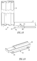
- a rail connector 471 can be disposed between two adjacent rails 200 to connect the rails 200. As shown in Figure 22 , the rail connector 471 can have a first end 477 attached to a middle portion 472 and a second end 476 attached to the middle portion 472.
- the middle portion 472 has an aperture 474 sized to receive a bolt, screw, or other fastener. A fastener that extends through the aperture 474 can connect the rail connector to the underside of a work surface or to some other component of furniture.
- the rail connector has flanges 475 that are spaced apart sufficiently to receive a portion of a rail 200 and support or hold that portion of the rail.
- at least one of the ends 476, 477 may be moveable relative to the middle portion 474.
- the entire rail connector is not moveable.
- the rail connector can be formed as a unitary structure.
- Connectors that may be inserted into slot 230 can be designed in a variety of configurations.
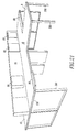
- One embodiment of the present invention includes a connector 100 that has two prongs 140 and a release mechanism 130, as shown in Figures 5 , 6 and 7 .
- Such a connector can be used for connecting work surfaces adjacent to each other or for connecting two other types of components of furniture together.
- the connector 100 has a frame 110, which may be composed of metal, plastic wood, or a combination thereof, that is connected to insert 120. Insert 120 is more clearly shown in Figures 8 and 9 .
- the insert is preferably made of plastic, elastic metal or another type of resilient material. In some embodiments of the present invention, the insert and frame can be formed as a unitary structure.
- insert 120 has a release mechanism 130 and prongs 140 attached to the body 117 of the insert. Each prong 140 is attached adjacent different sides of the release mechanism 130.
- prongs 140 snap into recess 206, best shown in Figure 1A or Figure 17 .
- the prong 140 remains within recess 206 until released by actuating release mechanism 130.
- Release mechanism 130 is actuated by pressing protrusion 139 toward the top of connector 100, in the direction indicated by arrow 132. The force applied to the protrusion 139 causes the insert to move away from the recess, releasing the prong 140 from the recess 206.
- release mechanisms can be provided to move prongs 140 when the release mechanism is actuated.
- a button, rotatable knob, slidable switch or other actuator could be attached to the body 117 of the insert so that actuation of the actuator causes the prongs to move.
- multiple protrusions could be attached to the body 117 so that movement of each protrusion moved a respective prong.
- the body 117 could be configured so that pulling the protrusion in a direction opposite arrow 132 would cause the prongs to move such that the prongs could move away from recess 206.
- prongs 140 and release mechanism130 are shown extending from the body in the same direction, it is also possible to configure the protrusion and prongs so that the prongs extend from one side of the body 117 and the protrusion extends from a different side of the body.
- Figures 10 and 11 show a one sided insert 125 that can be used to connect accessories such as wrist rests, pen trays, pencil trays, cable trays, other holders, panels, light partitions, storage devices or other apparatuses to the work surface 9 or other components of furniture.
- fastener 150 can have insert 125 connected to a pen tray 86, as shown in Figure 19 , so pen tray 86 can be connected to a work surface or other component of furniture.
- Connector 105 has a first frame portion 126 connected to a second frame portion 106. Insert 125 is connected to frame portion 126. Projection 141 is attached to portion 126 and projection 142 is attached to portion 106. Projection 141 extends from portion 126 downward toward projection 142 and projection 142 extends upward from portion 106 toward projection 141.
- Such a configuration of projections 141 and 142 define jaws 160 that are sized and configured to receive and hold components of furniture such as storage devices and furniture accessories.
- connector 105 can be connected to a work surface or other component of furniture.
- Portion 126 can be inserted into slot 230 so that prong 140 of insert 125 fits within recess 206. Additional components or devices can then be held within jaws 160 of the connector 105.
- Portion 106 and portion 126 can be connected by various different fasteners or be formed as one unitary structure.
- bolts or other fastening devices can extend through apertures 107 in the connector to connect portion 126 with portion 106.
- another embodiment of the present invention can have connector 133 attached to cable tray 145.
- the connector 133 can have prong 140 and release mechanism 130 extend from the body of the connector.
- the body of the connector 133 can have a first portion 67 attached to a perpendicular second portion 61.
- the second portion 61 is attached to the cable tray 145.
- the cable tray 145 is sized and configured to retain cables that may be used in connection with equipment stored on the work surface 9 such as computers, servers, and other electronic devices or network devices.
- connector 133 can also be connected to other holders or storage devices.
- a connector 136 can also be attached to a modesty panel 310 or other panel that can provide privacy to a work area.
- the connector 136 can be inserted into slot 230 until prong 140 is locked within recess 206.
- the connector can then hold the panel 310 adjacent the work surface 9. If a user desires to remove panel 310, the user may separate the panel from the work surface 9 by pulling on release mechanism 130. Pulling on release mechanism 130 causes prong 140 to move away from recess 206 so the connector 136 can be moved in a direction transverse and away from slot 230.
- a technical panel 70, or storage device, sized and configured to hold wires, books or other devices can be connected to a connector 137.
- Connector 137 can be connected and separated from the work surface 9 similarly to connector 136.
- the connectors may be slid along the slot 230 if the recesses 206 are sized and configured to extend along the entire slot 230. Because the connectors can slide along the slot 230, the components of furniture attached to the connector can be easily maneuvered or adjusted to meet changing office or room configurations or other work space needs.
- the recesses 206 can be positioned such that a plurality of recesses is defined in the rail 200 adjacent each slot 230. The size and configuration of such recesses can prevent connectors from movement along the slot or limit their movement along the slot.
- one embodiment of the present invention can include a desk or office work station, as shown in Figure 20 .
- the table 10 is connected to a technical panel 70 by one or more connectors.
- the technical panel is configured with a slot that is configured to receive a hook or connector 133 attached to a paper container 80.
- a bulletin board 82 may also be connected to the technical panel 70.
- One or more fasteners or connectors connect a blotter 84 to the work surface 9 of the table.
- the blotter 84 may be slidable along the slot 230 formed along the perimeter of the table.
- Another embodiment of the present invention can include large work stations formed from multiple tables 10 connected together by connectors 100.
- Tech panels 70 are connected to the tables 10 by connectors 137.
- Pen tray 86 and wrist rest 89 are also connected to different tables 10.
- the pen holders 86 and paper containers 80 are preferably configured to hold pencils, paper clips, papers or other tools that may be used by personnel working at or near the work station.
Landscapes
- Engineering & Computer Science (AREA)
- General Engineering & Computer Science (AREA)
- Mechanical Engineering (AREA)
- Connection Of Plates (AREA)
- Furniture Connections (AREA)
Claims (14)
- Modulares Möbelsystem, umfassend:Wenigstens ein Möbelbauteil (9, 10, 70, 200) und wenigstens ein Verbindungselement (100), das einen Einsatz (120) mit einem Körper (117) und einen am Körper angebrachten Auslösemechanismus (130) umfasst, dadurch gekennzeichnet, dass das Möbelbauteil wenigstens einen Schlitz (230) und wenigstens eine an den Schlitz angrenzende Aussparung (206) aufweist; das wenigstens eine Verbindungselement (100), das wenigstens eine am Körper angebrachte Zacke (140) umfasst, wobei die wenigstens eine Zacke (140) bemessen und konfiguriert ist, in die wenigstens eine Aussparung in dem wenigstens einen Möbelbauteil zu passen, wobei wenigstens ein Abschnitt des wenigstens einen Verbindungselements bemessen und konfiguriert ist, in wenigstens einen Schlitz aufgenommen zu werden, wenn die wenigstens eine Zacke in der wenigstens einen Aussparung positioniert ist, wobei der wenigstens eine Auslösemechanismus aus einem ersten Vorsprung (139) besteht, der wenigstens eine Auslösemechanismus integral an die wenigstens eine Zacke derart angebracht ist, das Bewegung des ersten Vorsprungs (139) bewirkt, dass sich die wenigstens eine Zacke bewegt;wobei die wenigstens eine Zacke innerhalb der wenigstens einen Aussparung positionierbar ist, um das wenigstens eine Verbindungselement lösbar mit dem wenigstens einen Möbelbauteil zu verbinden und, wobei die Betätigung des wenigstens einen Auslösemechanismus bewirkt, dass sich die wenigstens eine Zacke von der wenigstens einen Aussparung derart wegbewegt, dass sich das wenigstens eine Verbindungselement von dem wenigstens einen Möbelbauteil trennen lässt.
- System nach Anspruch 1, wobei das wenigstens eine Möbelbauteil (9, 10, 70, 200) wenigstens ein Bauteil ist, das aus der Gruppe selektiert wurde, die aus leichten Panels, Aufbewahrungseinrichtungen, technischen Panels, Bleistifthaltern, Arbeitsflächen und Kabelträgern besteht.
- System nach Anspruch 1, wobei das wenigstens eine Möbelbauteil aus wenigstens einer Schiene (206) besteht, die an eine Struktur derart angebracht ist, dass der wenigstens eine Schlitz (230) zwischen der Struktur und der wenigstens einen Schiene gebildet wird, wobei die wenigstens eine Schiene wenigstens eine Nut (215) aufweist, welche die wenigstens eine, an den Schlitz angrenzende, Aussparung definiert.
- System nach Anspruch 3, wobei die wenigstens eine Schiene aus einem Material besteht, das aus der Gruppe selektiert wurde, die aus Metallen, Holz und Kunststoffen besteht.
- System nach Anspruch 3, wobei die wenigstens eine Schiene aus einer ersten Schiene und einer zweiten Schiene besteht und das wenigstens eine Möbelbauteil ferner aus einem Schienenverbindungselement (471) besteht, das zwischen den ersten und zweiten Schienen positioniert (476) ist, wobei das Schienenverbindungselement ein erstes Ende (477) und ein zweites Ende (476) aufweist, wobei das erste Ende des Schienenverbindungselements an der ersten Schiene angebracht ist und das zweite Ende des Schienenverbindungselements an der zweiten Schiene angebracht ist.
- System nach Anspruch 3, wobei die Struktur einen Umfang aufweist und die wenigstens eine Schiene an die Struktur an den Umfang der Struktur angrenzend angebracht ist.
- System nach Anspruch 3, wobei die wenigstens eine Schiene eine Innenseite und eine Außenseite aufweist, der wenigstens eine Schlitz aus einem ersten Schlitz (230) und einem zweiten Schlitz (230) besteht, der erste Schlitz zwischen der Innenseite der wenigstens einen Schiene und der Struktur definiert ist, der zweite Schlitz zwischen der Außenseite der wenigstens einen Schiene und der Struktur definiert ist und, wobei die wenigstens eine Nut (215) aus einer ersten Nut angrenzend an den ersten Schlitz und einer zweiten Nut angrenzend an den zweiten Schlitz besteht.
- System nach Anspruch 1, wobei das wenigstens eine Verbindungselement eine Vielzahl von Verbindungselementen ist und das wenigstens eine Möbelbauteil eine Vielzahl von Möbelbauteilen ist.
- System nach Anspruch 1, wobei das wenigstens eine Möbelbauteil aus einer Vielzahl von Möbelbauteilen besteht, das System ferner einen Möbelartikel umfasst, der aus der Vielzahl von Möbelbauteilen und dem wenigstens einen Verbindungselement besteht, wobei das wenigstens eine Verbindungselement die Vielzahl der Bauteile miteinander verbindet.
- System nach Anspruch 1, das ferner wenigstens eine Vorrichtung (125) umfasst, die konfiguriert ist, mit dem wenigstens einen Möbelbauteil verbunden zu werden, wobei die wenigstens eine Vorrichtung aus einem Körper besteht, der an das wenigstens eine Befestigungselement angebracht ist, wobei das wenigstens eine Befestigungselement wenigstens einen Auslösemechanismus und wenigstens eine Zacke aufweist, die wenigstens eine Zacke bemessen und konfiguriert ist, in die wenigstens eine Aussparung im wenigstens einen Möbelbauteil zu passen, wobei der wenigstens eine Auslösemechanismus derart an den Körper des wenigstens einen Befestigungselements angebracht, dass Betätigung des wenigstens einen Auslösemechanismus bewirkt, dass sich die wenigstens eine Zacke bewegt.
- System nach Anspruch 10, wobei die wenigstens eine Einrichtung eine Vorrichtung ist, die aus der Gruppe selektiert wurde, die aus Panels, Haltern, Aufbewahrungseinrichtungen und Kabelträgern besteht.
- System nach Anspruch 1, wobei wenigstens ein Verbindungselement aus einem ersten Verbindungselement besteht, wobei der wenigstens eine Auslösemechanismus des ersten Verbindungselements aus einem am Körper angebrachten ersten Vorsprung besteht, derart, dass Bewegung des ersten Vorsprungs bewirkt, dass sich wenigstens eine Zacke bewegt, wobei der erste Vorsprung durch eine Kraft betätigt wird, die auf den ersten Vorsprung angewandt wird.
- System nach Anspruch 12, wobei der erste Vorsprung eine erste Seite und eine zweite Seite aufweist und, wobei die wenigstens eine Zacke aus einer ersten Zacke und einer zweiten Zacke besteht, wobei die erste Zacke am Körper angebracht ist, der an die erste Seite des ersten Vorsprungs angrenzt und die zweite Zacke am Körper angebracht ist, der an die zweite Seite des ersten Vorsprungs angrenzt.
- System nach Anspruch 1, wobei die Betätigung des wenigstens einen Auslösemechanismus bewirkt, dass sich die wenigstens eine Zacke von der wenigstens einen Aussparung in einer Richtung wegbewegt, die transversal zu der wenigstens einen Aussparung ist, derart, dass sich die wenigstens eine Zacke aus der wenigstens einen Aussparung und dem wenigstens einen Schlitz entfernen lässt, indem das wenigstens eine Verbindungselement in eine Richtung bewegt wird, die im Wesentlichen transversal zum wenigstens einen Schlitz ist.
Applications Claiming Priority (2)
| Application Number | Priority Date | Filing Date | Title |
|---|---|---|---|
| US79206106P | 2006-04-14 | 2006-04-14 | |
| PCT/EP2007/053650 WO2007118864A2 (en) | 2006-04-14 | 2007-04-13 | Modular furniture system |
Publications (2)
| Publication Number | Publication Date |
|---|---|
| EP2007243A2 EP2007243A2 (de) | 2008-12-31 |
| EP2007243B1 true EP2007243B1 (de) | 2016-04-13 |
Family
ID=38609855
Family Applications (1)
| Application Number | Title | Priority Date | Filing Date |
|---|---|---|---|
| EP07728115.2A Not-in-force EP2007243B1 (de) | 2006-04-14 | 2007-04-13 | Modulares möbelsystem |
Country Status (4)
| Country | Link |
|---|---|
| US (1) | US8132371B2 (de) |
| EP (1) | EP2007243B1 (de) |
| CA (1) | CA2648888C (de) |
| WO (1) | WO2007118864A2 (de) |
Families Citing this family (10)
| Publication number | Priority date | Publication date | Assignee | Title |
|---|---|---|---|---|
| EP2579744B1 (de) | 2010-06-08 | 2015-03-18 | Knoll, Inc. | Möbelsystem und verfahren zur montage eines möbelstücks für einen arbeitsbereich |
| US9730513B2 (en) | 2015-06-01 | 2017-08-15 | Knoll, Inc. | Modular furniture unit having power distribution |
| US10842266B2 (en) | 2018-05-23 | 2020-11-24 | Herman Miller, Inc. | Furniture system |
| US11457732B2 (en) | 2020-01-10 | 2022-10-04 | MillerKnoll, Inc. | Chase for connecting tables |
| TWI712382B (zh) * | 2020-01-10 | 2020-12-11 | 川湖科技股份有限公司 | 連接裝置 |
| US12016455B2 (en) | 2020-06-19 | 2024-06-25 | Knoll, Inc. | Work surface height adjustment stop apparatus and method of utilizing same |
| US11549537B2 (en) | 2020-06-19 | 2023-01-10 | Knoll, Inc. | Article of furniture and method of installing same |
| US11944208B2 (en) | 2021-06-14 | 2024-04-02 | Knoll, Inc. | Chair and method of making the chair |
| US11877646B2 (en) | 2021-07-12 | 2024-01-23 | Knoll, Inc. | Work surface attachment mechanism, article of furniture, and method of making the article of furniture |
| WO2024102949A2 (en) * | 2022-11-10 | 2024-05-16 | Evan Clabots Design LLC | Modular lounge seating assembly system |
Family Cites Families (26)
| Publication number | Priority date | Publication date | Assignee | Title |
|---|---|---|---|---|
| US2096319A (en) * | 1936-06-25 | 1937-10-19 | United Carr Fastener Corp | Snap fastener mounting bracket and installation thereof |
| US2516907A (en) * | 1945-07-09 | 1950-08-01 | H A Douglas Mfg Co | Coupling |
| US2501940A (en) * | 1946-11-12 | 1950-03-28 | Hibbard Hurl | Detachable utensil handle |
| US2879561A (en) * | 1953-10-05 | 1959-03-31 | Rieder Brothers | Knockdown counter construction |
| US2824315A (en) * | 1955-03-15 | 1958-02-25 | George D Mckenny | Releasable coupling device |
| US3639950A (en) * | 1968-09-13 | 1972-02-08 | Itt | Latching device |
| US4245879A (en) * | 1978-06-12 | 1981-01-20 | Magnetic Controls Company | Latch assembly |
| DE3047642A1 (de) * | 1980-12-17 | 1982-10-28 | Arturo Salice S.p.A., 22060 Novedrate, Como | Verbindungsbeschlag |
| US4530136A (en) * | 1982-09-24 | 1985-07-23 | Sunline Hardware, Inc. | Bayonet-type latch mechanism with positive locking function |
| EP0160057B1 (de) * | 1983-10-28 | 1988-03-30 | PAUL HETTICH GMBH & CO. | Verbindungsbeschlag |
| US4643610A (en) * | 1986-06-30 | 1987-02-17 | Chrysler Motors Corporation | Fastener mounting assembly |
| JPH01203705A (ja) * | 1988-02-04 | 1989-08-16 | Kazuhiro Matsui | 板状体の組立具 |
| SE9102766L (sv) * | 1991-09-24 | 1993-02-15 | Nils Gunnar Jansson | Foerfarande jaemte anordning foer saekrande av fasadelement av glas |
| DE4437228C2 (de) | 1994-10-19 | 1996-10-10 | Dyes Bueromoebelwerk | Bürotisch mit einem Koppelmechanismus für Anbauelemente |
| DE9418644U1 (de) * | 1994-11-22 | 1995-01-26 | Heinrich Baumgarten KG, Spezialfabrik für Beschlagteile, 57290 Neunkirchen | Griffbefestigung |
| US5577779A (en) * | 1994-12-22 | 1996-11-26 | Yazaki Corporation | Snap fit lock with release feature |
| DK171323B1 (da) * | 1995-05-19 | 1996-09-09 | Siso A S | Koblingsbeslag af metalplade til udløselig sammenkobling af endekanter af bordplader |
| JPH1145757A (ja) * | 1997-07-29 | 1999-02-16 | Hirose Electric Co Ltd | コネクタのスライド式ロックレバー解除機構 |
| US20020023391A1 (en) * | 1997-09-03 | 2002-02-28 | Nymark R. Paul | Wall and display systems and components |
| ES2152742T3 (es) | 1998-03-02 | 2001-02-01 | Steelcase Strafor Sa | Pieza de union entre dos viguetas deslizables en la misma. |
| AU738130B2 (en) | 1998-06-16 | 2001-09-06 | Kokuyo Co., Ltd. | Desk |
| US6199328B1 (en) * | 1998-12-11 | 2001-03-13 | Owens Corning Fiberglas Technology, Inc. | Clamp assembly for attaching panels to substrate |
| DE10142508A1 (de) * | 2001-08-30 | 2003-03-27 | Bsh Bosch Siemens Hausgeraete | Rastvorrichtung und mit dieser ausgestattete Küchenmaschine |
| SE524721C2 (sv) * | 2002-07-29 | 2004-09-21 | Upglaze Hb | Fästanordning vid glasfasader för montering av isolerglas |
| WO2005018383A1 (en) | 2003-08-22 | 2005-03-03 | Radoslaw Lasota | Modular components |
| US20060102056A1 (en) * | 2004-11-16 | 2006-05-18 | Wolfe Kevin M | Removable table extension |
-
2007
- 2007-04-13 EP EP07728115.2A patent/EP2007243B1/de not_active Not-in-force
- 2007-04-13 CA CA2648888A patent/CA2648888C/en not_active Expired - Fee Related
- 2007-04-13 US US12/296,711 patent/US8132371B2/en not_active Expired - Fee Related
- 2007-04-13 WO PCT/EP2007/053650 patent/WO2007118864A2/en not_active Ceased
Also Published As
| Publication number | Publication date |
|---|---|
| CA2648888A1 (en) | 2007-10-25 |
| US8132371B2 (en) | 2012-03-13 |
| CA2648888C (en) | 2011-11-15 |
| US20090206716A1 (en) | 2009-08-20 |
| EP2007243A2 (de) | 2008-12-31 |
| WO2007118864A2 (en) | 2007-10-25 |
| WO2007118864A3 (en) | 2008-08-28 |
Similar Documents
| Publication | Publication Date | Title |
|---|---|---|
| EP2007243B1 (de) | Modulares möbelsystem | |
| EP2575539B1 (de) | Neukonfigurierbare tischanordnungen | |
| CA2799938C (en) | Frame type table assemblies | |
| US10681980B2 (en) | Frame type workstation configurations | |
| CA2741905C (en) | Split top table assemblies | |
| WO2007146134A2 (en) | Adaptable bi-fold scrapbook and craft workstation | |
| US20120181904A1 (en) | Multifunctional storage box | |
| WO1992005724A1 (en) | Interchangeable modular furniture | |
| KR101495638B1 (ko) | 가구 조립 셋트 | |
| KR102207328B1 (ko) | 압출프레임과 가압고정체에 의한 테이블 부속 설치구 | |
| JP7589489B2 (ja) | テーブル | |
| JP3575530B2 (ja) | キャビネットとパネル装置との組み合わせ | |
| US11304507B2 (en) | Modular component desk system | |
| CN111345615A (zh) | 用于抽屉前部的安装装置 | |
| JP7150471B2 (ja) | 天板付き什器 | |
| EP1535536A1 (de) | Vorrichtung zum lösbaren Befestigen einer Steckdosenleiste an einem Möbelstück | |
| KR200219417Y1 (ko) | 다용도 수납장 | |
| KR200227748Y1 (ko) | 다용도 수납장 | |
| AU2013204849B2 (en) | A mounting assembly | |
| KR200380813Y1 (ko) | 다용도 수납장 | |
| KR0126563Y1 (ko) | 다목적 조립가구 | |
| KR20020043431A (ko) | 다용도 수납장 | |
| KR20070063072A (ko) | 다용도 수납장 | |
| EP0786951A1 (de) | Gestellsystem für compact discs, schubladen etc. | |
| HK1178404A (en) | Furniture component fastening apparatus, furniture system and method of assembling furniture for a work space |
Legal Events
| Date | Code | Title | Description |
|---|---|---|---|
| PUAI | Public reference made under article 153(3) epc to a published international application that has entered the european phase |
Free format text: ORIGINAL CODE: 0009012 |
|
| 17P | Request for examination filed |
Effective date: 20080918 |
|
| AK | Designated contracting states |
Kind code of ref document: A2 Designated state(s): AT BE BG CH CY CZ DE DK EE ES FI FR GB GR HU IE IS IT LI LT LU LV MC MT NL PL PT RO SE SI SK TR |
|
| AX | Request for extension of the european patent |
Extension state: AL BA HR MK RS |
|
| 17Q | First examination report despatched |
Effective date: 20090407 |
|
| DAX | Request for extension of the european patent (deleted) | ||
| REG | Reference to a national code |
Ref country code: DE Ref legal event code: R079 Ref document number: 602007045789 Country of ref document: DE Free format text: PREVIOUS MAIN CLASS: A47B0017030000 Ipc: F16B0012260000 |
|
| RIC1 | Information provided on ipc code assigned before grant |
Ipc: F16B 12/26 20060101AFI20150916BHEP Ipc: F16B 12/44 20060101ALI20150916BHEP |
|
| GRAP | Despatch of communication of intention to grant a patent |
Free format text: ORIGINAL CODE: EPIDOSNIGR1 |
|
| INTG | Intention to grant announced |
Effective date: 20151110 |
|
| GRAS | Grant fee paid |
Free format text: ORIGINAL CODE: EPIDOSNIGR3 |
|
| RAP1 | Party data changed (applicant data changed or rights of an application transferred) |
Owner name: KNOLL INTERNATIONAL S.P.A. |
|
| GRAA | (expected) grant |
Free format text: ORIGINAL CODE: 0009210 |
|
| RIN1 | Information on inventor provided before grant (corrected) |
Inventor name: KRUSIN, MARK Inventor name: GOLINSKI, STEFAN Inventor name: LISSONI, PIERO |
|
| AK | Designated contracting states |
Kind code of ref document: B1 Designated state(s): AT BE BG CH CY CZ DE DK EE ES FI FR GB GR HU IE IS IT LI LT LU LV MC MT NL PL PT RO SE SI SK TR |
|
| REG | Reference to a national code |
Ref country code: GB Ref legal event code: FG4D |
|
| REG | Reference to a national code |
Ref country code: AT Ref legal event code: REF Ref document number: 790486 Country of ref document: AT Kind code of ref document: T Effective date: 20160415 Ref country code: CH Ref legal event code: EP |
|
| REG | Reference to a national code |
Ref country code: FR Ref legal event code: PLFP Year of fee payment: 10 |
|
| REG | Reference to a national code |
Ref country code: IE Ref legal event code: FG4D |
|
| REG | Reference to a national code |
Ref country code: DE Ref legal event code: R096 Ref document number: 602007045789 Country of ref document: DE |
|
| REG | Reference to a national code |
Ref country code: LT Ref legal event code: MG4D |
|
| PG25 | Lapsed in a contracting state [announced via postgrant information from national office to epo] |
Ref country code: BE Free format text: LAPSE BECAUSE OF NON-PAYMENT OF DUE FEES Effective date: 20160430 |
|
| REG | Reference to a national code |
Ref country code: AT Ref legal event code: MK05 Ref document number: 790486 Country of ref document: AT Kind code of ref document: T Effective date: 20160413 |
|
| REG | Reference to a national code |
Ref country code: NL Ref legal event code: MP Effective date: 20160413 |
|
| PG25 | Lapsed in a contracting state [announced via postgrant information from national office to epo] |
Ref country code: FI Free format text: LAPSE BECAUSE OF FAILURE TO SUBMIT A TRANSLATION OF THE DESCRIPTION OR TO PAY THE FEE WITHIN THE PRESCRIBED TIME-LIMIT Effective date: 20160413 Ref country code: PL Free format text: LAPSE BECAUSE OF FAILURE TO SUBMIT A TRANSLATION OF THE DESCRIPTION OR TO PAY THE FEE WITHIN THE PRESCRIBED TIME-LIMIT Effective date: 20160413 Ref country code: LT Free format text: LAPSE BECAUSE OF FAILURE TO SUBMIT A TRANSLATION OF THE DESCRIPTION OR TO PAY THE FEE WITHIN THE PRESCRIBED TIME-LIMIT Effective date: 20160413 Ref country code: NL Free format text: LAPSE BECAUSE OF FAILURE TO SUBMIT A TRANSLATION OF THE DESCRIPTION OR TO PAY THE FEE WITHIN THE PRESCRIBED TIME-LIMIT Effective date: 20160413 |
|
| PG25 | Lapsed in a contracting state [announced via postgrant information from national office to epo] |
Ref country code: ES Free format text: LAPSE BECAUSE OF FAILURE TO SUBMIT A TRANSLATION OF THE DESCRIPTION OR TO PAY THE FEE WITHIN THE PRESCRIBED TIME-LIMIT Effective date: 20160413 Ref country code: LV Free format text: LAPSE BECAUSE OF FAILURE TO SUBMIT A TRANSLATION OF THE DESCRIPTION OR TO PAY THE FEE WITHIN THE PRESCRIBED TIME-LIMIT Effective date: 20160413 Ref country code: SE Free format text: LAPSE BECAUSE OF FAILURE TO SUBMIT A TRANSLATION OF THE DESCRIPTION OR TO PAY THE FEE WITHIN THE PRESCRIBED TIME-LIMIT Effective date: 20160413 Ref country code: PT Free format text: LAPSE BECAUSE OF FAILURE TO SUBMIT A TRANSLATION OF THE DESCRIPTION OR TO PAY THE FEE WITHIN THE PRESCRIBED TIME-LIMIT Effective date: 20160816 Ref country code: AT Free format text: LAPSE BECAUSE OF FAILURE TO SUBMIT A TRANSLATION OF THE DESCRIPTION OR TO PAY THE FEE WITHIN THE PRESCRIBED TIME-LIMIT Effective date: 20160413 Ref country code: GR Free format text: LAPSE BECAUSE OF FAILURE TO SUBMIT A TRANSLATION OF THE DESCRIPTION OR TO PAY THE FEE WITHIN THE PRESCRIBED TIME-LIMIT Effective date: 20160714 |
|
| REG | Reference to a national code |
Ref country code: CH Ref legal event code: PL |
|
| PG25 | Lapsed in a contracting state [announced via postgrant information from national office to epo] |
Ref country code: BE Free format text: LAPSE BECAUSE OF FAILURE TO SUBMIT A TRANSLATION OF THE DESCRIPTION OR TO PAY THE FEE WITHIN THE PRESCRIBED TIME-LIMIT Effective date: 20160413 |
|
| REG | Reference to a national code |
Ref country code: DE Ref legal event code: R097 Ref document number: 602007045789 Country of ref document: DE |
|
| REG | Reference to a national code |
Ref country code: IE Ref legal event code: MM4A |
|
| PG25 | Lapsed in a contracting state [announced via postgrant information from national office to epo] |
Ref country code: CZ Free format text: LAPSE BECAUSE OF FAILURE TO SUBMIT A TRANSLATION OF THE DESCRIPTION OR TO PAY THE FEE WITHIN THE PRESCRIBED TIME-LIMIT Effective date: 20160413 Ref country code: RO Free format text: LAPSE BECAUSE OF FAILURE TO SUBMIT A TRANSLATION OF THE DESCRIPTION OR TO PAY THE FEE WITHIN THE PRESCRIBED TIME-LIMIT Effective date: 20160413 Ref country code: LI Free format text: LAPSE BECAUSE OF NON-PAYMENT OF DUE FEES Effective date: 20160430 Ref country code: EE Free format text: LAPSE BECAUSE OF FAILURE TO SUBMIT A TRANSLATION OF THE DESCRIPTION OR TO PAY THE FEE WITHIN THE PRESCRIBED TIME-LIMIT Effective date: 20160413 Ref country code: SK Free format text: LAPSE BECAUSE OF FAILURE TO SUBMIT A TRANSLATION OF THE DESCRIPTION OR TO PAY THE FEE WITHIN THE PRESCRIBED TIME-LIMIT Effective date: 20160413 Ref country code: CH Free format text: LAPSE BECAUSE OF NON-PAYMENT OF DUE FEES Effective date: 20160430 Ref country code: DK Free format text: LAPSE BECAUSE OF FAILURE TO SUBMIT A TRANSLATION OF THE DESCRIPTION OR TO PAY THE FEE WITHIN THE PRESCRIBED TIME-LIMIT Effective date: 20160413 |
|
| PLBE | No opposition filed within time limit |
Free format text: ORIGINAL CODE: 0009261 |
|
| STAA | Information on the status of an ep patent application or granted ep patent |
Free format text: STATUS: NO OPPOSITION FILED WITHIN TIME LIMIT |
|
| 26N | No opposition filed |
Effective date: 20170116 |
|
| REG | Reference to a national code |
Ref country code: FR Ref legal event code: PLFP Year of fee payment: 11 |
|
| PG25 | Lapsed in a contracting state [announced via postgrant information from national office to epo] |
Ref country code: SI Free format text: LAPSE BECAUSE OF FAILURE TO SUBMIT A TRANSLATION OF THE DESCRIPTION OR TO PAY THE FEE WITHIN THE PRESCRIBED TIME-LIMIT Effective date: 20160413 Ref country code: IE Free format text: LAPSE BECAUSE OF NON-PAYMENT OF DUE FEES Effective date: 20160413 |
|
| PG25 | Lapsed in a contracting state [announced via postgrant information from national office to epo] |
Ref country code: MC Free format text: LAPSE BECAUSE OF FAILURE TO SUBMIT A TRANSLATION OF THE DESCRIPTION OR TO PAY THE FEE WITHIN THE PRESCRIBED TIME-LIMIT Effective date: 20160413 |
|
| REG | Reference to a national code |
Ref country code: FR Ref legal event code: PLFP Year of fee payment: 12 |
|
| PG25 | Lapsed in a contracting state [announced via postgrant information from national office to epo] |
Ref country code: HU Free format text: LAPSE BECAUSE OF FAILURE TO SUBMIT A TRANSLATION OF THE DESCRIPTION OR TO PAY THE FEE WITHIN THE PRESCRIBED TIME-LIMIT; INVALID AB INITIO Effective date: 20070413 Ref country code: CY Free format text: LAPSE BECAUSE OF FAILURE TO SUBMIT A TRANSLATION OF THE DESCRIPTION OR TO PAY THE FEE WITHIN THE PRESCRIBED TIME-LIMIT Effective date: 20160413 |
|
| PG25 | Lapsed in a contracting state [announced via postgrant information from national office to epo] |
Ref country code: TR Free format text: LAPSE BECAUSE OF FAILURE TO SUBMIT A TRANSLATION OF THE DESCRIPTION OR TO PAY THE FEE WITHIN THE PRESCRIBED TIME-LIMIT Effective date: 20160413 Ref country code: LU Free format text: LAPSE BECAUSE OF NON-PAYMENT OF DUE FEES Effective date: 20160413 Ref country code: IS Free format text: LAPSE BECAUSE OF FAILURE TO SUBMIT A TRANSLATION OF THE DESCRIPTION OR TO PAY THE FEE WITHIN THE PRESCRIBED TIME-LIMIT Effective date: 20160413 Ref country code: MT Free format text: LAPSE BECAUSE OF NON-PAYMENT OF DUE FEES Effective date: 20160430 |
|
| PG25 | Lapsed in a contracting state [announced via postgrant information from national office to epo] |
Ref country code: BG Free format text: LAPSE BECAUSE OF FAILURE TO SUBMIT A TRANSLATION OF THE DESCRIPTION OR TO PAY THE FEE WITHIN THE PRESCRIBED TIME-LIMIT Effective date: 20160413 |
|
| PGFP | Annual fee paid to national office [announced via postgrant information from national office to epo] |
Ref country code: DE Payment date: 20200429 Year of fee payment: 14 Ref country code: FR Payment date: 20200427 Year of fee payment: 14 |
|
| PGFP | Annual fee paid to national office [announced via postgrant information from national office to epo] |
Ref country code: IT Payment date: 20200423 Year of fee payment: 14 Ref country code: GB Payment date: 20200427 Year of fee payment: 14 |
|
| REG | Reference to a national code |
Ref country code: DE Ref legal event code: R119 Ref document number: 602007045789 Country of ref document: DE |
|
| GBPC | Gb: european patent ceased through non-payment of renewal fee |
Effective date: 20210413 |
|
| PG25 | Lapsed in a contracting state [announced via postgrant information from national office to epo] |
Ref country code: FR Free format text: LAPSE BECAUSE OF NON-PAYMENT OF DUE FEES Effective date: 20210430 Ref country code: GB Free format text: LAPSE BECAUSE OF NON-PAYMENT OF DUE FEES Effective date: 20210413 Ref country code: DE Free format text: LAPSE BECAUSE OF NON-PAYMENT OF DUE FEES Effective date: 20211103 |
|
| PG25 | Lapsed in a contracting state [announced via postgrant information from national office to epo] |
Ref country code: IT Free format text: LAPSE BECAUSE OF NON-PAYMENT OF DUE FEES Effective date: 20200413 |
|
| PG25 | Lapsed in a contracting state [announced via postgrant information from national office to epo] |
Ref country code: IT Free format text: LAPSE BECAUSE OF NON-PAYMENT OF DUE FEES Effective date: 20210413 |