EP2007233B1 - Article à fumer doté d'un limiteur d'écoulement - Google Patents
Article à fumer doté d'un limiteur d'écoulement Download PDFInfo
- Publication number
- EP2007233B1 EP2007233B1 EP07732198.2A EP07732198A EP2007233B1 EP 2007233 B1 EP2007233 B1 EP 2007233B1 EP 07732198 A EP07732198 A EP 07732198A EP 2007233 B1 EP2007233 B1 EP 2007233B1
- Authority
- EP
- European Patent Office
- Prior art keywords
- filter
- segment
- smoking article
- restrictor
- flow restricting
- Prior art date
- Legal status (The legal status is an assumption and is not a legal conclusion. Google has not performed a legal analysis and makes no representation as to the accuracy of the status listed.)
- Active
Links
- 230000000391 smoking effect Effects 0.000 title claims description 69
- 238000009423 ventilation Methods 0.000 claims description 84
- 238000011144 upstream manufacturing Methods 0.000 claims description 47
- 239000000779 smoke Substances 0.000 claims description 42
- 241000208125 Nicotiana Species 0.000 claims description 39
- 235000002637 Nicotiana tabacum Nutrition 0.000 claims description 39
- 229920002301 cellulose acetate Polymers 0.000 claims description 32
- 239000000463 material Substances 0.000 claims description 26
- OKTJSMMVPCPJKN-UHFFFAOYSA-N Carbon Chemical compound [C] OKTJSMMVPCPJKN-UHFFFAOYSA-N 0.000 claims description 16
- 229910052799 carbon Inorganic materials 0.000 claims description 16
- 238000004519 manufacturing process Methods 0.000 claims description 16
- 238000000034 method Methods 0.000 claims description 15
- QTBSBXVTEAMEQO-UHFFFAOYSA-M Acetate Chemical compound CC([O-])=O QTBSBXVTEAMEQO-UHFFFAOYSA-M 0.000 claims description 9
- 239000003795 chemical substances by application Substances 0.000 claims description 6
- 238000001914 filtration Methods 0.000 claims description 5
- -1 polypropylene Polymers 0.000 claims description 5
- 239000004743 Polypropylene Substances 0.000 claims description 3
- 239000011248 coating agent Substances 0.000 claims description 3
- 238000000576 coating method Methods 0.000 claims description 3
- 229920001155 polypropylene Polymers 0.000 claims description 3
- XLYOFNOQVPJJNP-UHFFFAOYSA-N water Substances O XLYOFNOQVPJJNP-UHFFFAOYSA-N 0.000 claims description 3
- 239000004677 Nylon Substances 0.000 claims description 2
- 229920001903 high density polyethylene Polymers 0.000 claims description 2
- 239000004700 high-density polyethylene Substances 0.000 claims description 2
- 229920001778 nylon Polymers 0.000 claims description 2
- 239000002594 sorbent Substances 0.000 claims 1
- 235000019504 cigarettes Nutrition 0.000 description 25
- 238000005192 partition Methods 0.000 description 10
- UGFAIRIUMAVXCW-UHFFFAOYSA-N Carbon monoxide Chemical compound [O+]#[C-] UGFAIRIUMAVXCW-UHFFFAOYSA-N 0.000 description 9
- 229910002091 carbon monoxide Inorganic materials 0.000 description 9
- 238000000429 assembly Methods 0.000 description 7
- 239000002245 particle Substances 0.000 description 7
- 239000012071 phase Substances 0.000 description 6
- 239000004033 plastic Substances 0.000 description 6
- 229920003023 plastic Polymers 0.000 description 6
- 230000000712 assembly Effects 0.000 description 5
- 239000000796 flavoring agent Substances 0.000 description 5
- 235000019634 flavors Nutrition 0.000 description 5
- 239000007789 gas Substances 0.000 description 5
- PEDCQBHIVMGVHV-UHFFFAOYSA-N Glycerine Chemical compound OCC(O)CO PEDCQBHIVMGVHV-UHFFFAOYSA-N 0.000 description 4
- 230000009977 dual effect Effects 0.000 description 4
- 238000012384 transportation and delivery Methods 0.000 description 4
- 230000000694 effects Effects 0.000 description 3
- 230000004048 modification Effects 0.000 description 3
- 238000012986 modification Methods 0.000 description 3
- 244000037364 Cinnamomum aromaticum Species 0.000 description 2
- 235000014489 Cinnamomum aromaticum Nutrition 0.000 description 2
- 229920002472 Starch Polymers 0.000 description 2
- 239000000853 adhesive Substances 0.000 description 2
- 230000001070 adhesive effect Effects 0.000 description 2
- 239000000443 aerosol Substances 0.000 description 2
- 238000005119 centrifugation Methods 0.000 description 2
- 239000000470 constituent Substances 0.000 description 2
- 239000000835 fiber Substances 0.000 description 2
- 239000003292 glue Substances 0.000 description 2
- 235000011187 glycerol Nutrition 0.000 description 2
- 229910052751 metal Inorganic materials 0.000 description 2
- 239000002184 metal Substances 0.000 description 2
- 239000003921 oil Substances 0.000 description 2
- 235000019198 oils Nutrition 0.000 description 2
- 230000035699 permeability Effects 0.000 description 2
- 230000008569 process Effects 0.000 description 2
- 230000001105 regulatory effect Effects 0.000 description 2
- 125000006850 spacer group Chemical group 0.000 description 2
- 239000008107 starch Substances 0.000 description 2
- 235000019698 starch Nutrition 0.000 description 2
- URAYPUMNDPQOKB-UHFFFAOYSA-N triacetin Chemical compound CC(=O)OCC(OC(C)=O)COC(C)=O URAYPUMNDPQOKB-UHFFFAOYSA-N 0.000 description 2
- NOOLISFMXDJSKH-UTLUCORTSA-N (+)-Neomenthol Chemical compound CC(C)[C@@H]1CC[C@@H](C)C[C@@H]1O NOOLISFMXDJSKH-UTLUCORTSA-N 0.000 description 1
- 235000002764 Apium graveolens Nutrition 0.000 description 1
- 240000007087 Apium graveolens Species 0.000 description 1
- 235000005747 Carum carvi Nutrition 0.000 description 1
- 240000000467 Carum carvi Species 0.000 description 1
- 240000003538 Chamaemelum nobile Species 0.000 description 1
- 235000007866 Chamaemelum nobile Nutrition 0.000 description 1
- 244000223760 Cinnamomum zeylanicum Species 0.000 description 1
- 240000007154 Coffea arabica Species 0.000 description 1
- 235000002787 Coriandrum sativum Nutrition 0.000 description 1
- 244000018436 Coriandrum sativum Species 0.000 description 1
- NOOLISFMXDJSKH-UHFFFAOYSA-N DL-menthol Natural products CC(C)C1CCC(C)CC1O NOOLISFMXDJSKH-UHFFFAOYSA-N 0.000 description 1
- 240000002943 Elettaria cardamomum Species 0.000 description 1
- 241000208152 Geranium Species 0.000 description 1
- 240000004670 Glycyrrhiza echinata Species 0.000 description 1
- 235000001453 Glycyrrhiza echinata Nutrition 0.000 description 1
- 235000006200 Glycyrrhiza glabra Nutrition 0.000 description 1
- 235000017382 Glycyrrhiza lepidota Nutrition 0.000 description 1
- 239000004831 Hot glue Substances 0.000 description 1
- 235000010254 Jasminum officinale Nutrition 0.000 description 1
- 240000005385 Jasminum sambac Species 0.000 description 1
- 244000255365 Kaskarillabaum Species 0.000 description 1
- 244000178870 Lavandula angustifolia Species 0.000 description 1
- 235000010663 Lavandula angustifolia Nutrition 0.000 description 1
- 235000019501 Lemon oil Nutrition 0.000 description 1
- 235000007232 Matricaria chamomilla Nutrition 0.000 description 1
- 235000006679 Mentha X verticillata Nutrition 0.000 description 1
- 235000014749 Mentha crispa Nutrition 0.000 description 1
- 244000078639 Mentha spicata Species 0.000 description 1
- 235000002899 Mentha suaveolens Nutrition 0.000 description 1
- 235000001636 Mentha x rotundifolia Nutrition 0.000 description 1
- 244000179970 Monarda didyma Species 0.000 description 1
- 235000010672 Monarda didyma Nutrition 0.000 description 1
- MWUXSHHQAYIFBG-UHFFFAOYSA-N Nitric oxide Chemical compound O=[N] MWUXSHHQAYIFBG-UHFFFAOYSA-N 0.000 description 1
- ODUCDPQEXGNKDN-UHFFFAOYSA-N Nitrogen oxide(NO) Natural products O=N ODUCDPQEXGNKDN-UHFFFAOYSA-N 0.000 description 1
- 235000019502 Orange oil Nutrition 0.000 description 1
- 239000004698 Polyethylene Substances 0.000 description 1
- 239000004793 Polystyrene Substances 0.000 description 1
- 240000000513 Santalum album Species 0.000 description 1
- 235000008632 Santalum album Nutrition 0.000 description 1
- 235000009470 Theobroma cacao Nutrition 0.000 description 1
- 244000299461 Theobroma cacao Species 0.000 description 1
- 235000001484 Trigonella foenum graecum Nutrition 0.000 description 1
- 244000250129 Trigonella foenum graecum Species 0.000 description 1
- 235000009499 Vanilla fragrans Nutrition 0.000 description 1
- 244000263375 Vanilla tahitensis Species 0.000 description 1
- 235000012036 Vanilla tahitensis Nutrition 0.000 description 1
- 235000006886 Zingiber officinale Nutrition 0.000 description 1
- 244000273928 Zingiber officinale Species 0.000 description 1
- 238000010521 absorption reaction Methods 0.000 description 1
- 238000009825 accumulation Methods 0.000 description 1
- 230000009471 action Effects 0.000 description 1
- 239000003463 adsorbent Substances 0.000 description 1
- 239000001387 apium graveolens Substances 0.000 description 1
- 230000008901 benefit Effects 0.000 description 1
- WHGYBXFWUBPSRW-FOUAGVGXSA-N beta-cyclodextrin Chemical compound OC[C@H]([C@H]([C@@H]([C@H]1O)O)O[C@H]2O[C@@H]([C@@H](O[C@H]3O[C@H](CO)[C@H]([C@@H]([C@H]3O)O)O[C@H]3O[C@H](CO)[C@H]([C@@H]([C@H]3O)O)O[C@H]3O[C@H](CO)[C@H]([C@@H]([C@H]3O)O)O[C@H]3O[C@H](CO)[C@H]([C@@H]([C@H]3O)O)O3)[C@H](O)[C@H]2O)CO)O[C@@H]1O[C@H]1[C@H](O)[C@@H](O)[C@@H]3O[C@@H]1CO WHGYBXFWUBPSRW-FOUAGVGXSA-N 0.000 description 1
- 229920000704 biodegradable plastic Polymers 0.000 description 1
- 229920002988 biodegradable polymer Polymers 0.000 description 1
- 235000005300 cardamomo Nutrition 0.000 description 1
- 235000017803 cinnamon Nutrition 0.000 description 1
- 235000016213 coffee Nutrition 0.000 description 1
- 235000013353 coffee beverage Nutrition 0.000 description 1
- 235000020057 cognac Nutrition 0.000 description 1
- 239000003086 colorant Substances 0.000 description 1
- 239000002131 composite material Substances 0.000 description 1
- 150000001875 compounds Chemical class 0.000 description 1
- 230000006835 compression Effects 0.000 description 1
- 238000007906 compression Methods 0.000 description 1
- 238000010276 construction Methods 0.000 description 1
- 238000009792 diffusion process Methods 0.000 description 1
- 239000000945 filler Substances 0.000 description 1
- 239000006260 foam Substances 0.000 description 1
- 235000008397 ginger Nutrition 0.000 description 1
- 235000013773 glyceryl triacetate Nutrition 0.000 description 1
- 239000001087 glyceryl triacetate Substances 0.000 description 1
- 238000010438 heat treatment Methods 0.000 description 1
- 235000012907 honey Nutrition 0.000 description 1
- 230000003116 impacting effect Effects 0.000 description 1
- 238000002347 injection Methods 0.000 description 1
- 239000007924 injection Substances 0.000 description 1
- 238000003780 insertion Methods 0.000 description 1
- 230000037431 insertion Effects 0.000 description 1
- 239000001102 lavandula vera Substances 0.000 description 1
- 235000018219 lavender Nutrition 0.000 description 1
- 239000010501 lemon oil Substances 0.000 description 1
- 229940010454 licorice Drugs 0.000 description 1
- 229940041616 menthol Drugs 0.000 description 1
- 239000000203 mixture Substances 0.000 description 1
- 238000000465 moulding Methods 0.000 description 1
- 239000010502 orange oil Substances 0.000 description 1
- 229920002492 poly(sulfone) Polymers 0.000 description 1
- 229920000728 polyester Polymers 0.000 description 1
- 229920000573 polyethylene Polymers 0.000 description 1
- 229920000642 polymer Polymers 0.000 description 1
- 229920002223 polystyrene Polymers 0.000 description 1
- 229920002635 polyurethane Polymers 0.000 description 1
- 239000004814 polyurethane Substances 0.000 description 1
- 230000009467 reduction Effects 0.000 description 1
- 235000019719 rose oil Nutrition 0.000 description 1
- 239000010666 rose oil Substances 0.000 description 1
- 235000002020 sage Nutrition 0.000 description 1
- 239000000243 solution Substances 0.000 description 1
- 238000001179 sorption measurement Methods 0.000 description 1
- 239000000126 substance Substances 0.000 description 1
- 229960002622 triacetin Drugs 0.000 description 1
- 235000001019 trigonella foenum-graecum Nutrition 0.000 description 1
- 239000012808 vapor phase Substances 0.000 description 1
- 239000003039 volatile agent Substances 0.000 description 1
Images


Classifications
-
- A—HUMAN NECESSITIES
- A24—TOBACCO; CIGARS; CIGARETTES; SIMULATED SMOKING DEVICES; SMOKERS' REQUISITES
- A24D—CIGARS; CIGARETTES; TOBACCO SMOKE FILTERS; MOUTHPIECES FOR CIGARS OR CIGARETTES; MANUFACTURE OF TOBACCO SMOKE FILTERS OR MOUTHPIECES
- A24D3/00—Tobacco smoke filters, e.g. filter-tips, filtering inserts; Filters specially adapted for simulated smoking devices; Mouthpieces for cigars or cigarettes
- A24D3/02—Manufacture of tobacco smoke filters
- A24D3/0275—Manufacture of tobacco smoke filters for filters with special features
- A24D3/0283—Manufacture of tobacco smoke filters for filters with special features with means for a non-axial smoke flow
-
- A—HUMAN NECESSITIES
- A24—TOBACCO; CIGARS; CIGARETTES; SIMULATED SMOKING DEVICES; SMOKERS' REQUISITES
- A24D—CIGARS; CIGARETTES; TOBACCO SMOKE FILTERS; MOUTHPIECES FOR CIGARS OR CIGARETTES; MANUFACTURE OF TOBACCO SMOKE FILTERS OR MOUTHPIECES
- A24D3/00—Tobacco smoke filters, e.g. filter-tips, filtering inserts; Filters specially adapted for simulated smoking devices; Mouthpieces for cigars or cigarettes
- A24D3/04—Tobacco smoke filters characterised by their shape or structure
- A24D3/043—Tobacco smoke filters characterised by their shape or structure with ventilation means, e.g. air dilution
-
- A—HUMAN NECESSITIES
- A24—TOBACCO; CIGARS; CIGARETTES; SIMULATED SMOKING DEVICES; SMOKERS' REQUISITES
- A24D—CIGARS; CIGARETTES; TOBACCO SMOKE FILTERS; MOUTHPIECES FOR CIGARS OR CIGARETTES; MANUFACTURE OF TOBACCO SMOKE FILTERS OR MOUTHPIECES
- A24D3/00—Tobacco smoke filters, e.g. filter-tips, filtering inserts; Filters specially adapted for simulated smoking devices; Mouthpieces for cigars or cigarettes
- A24D3/02—Manufacture of tobacco smoke filters
- A24D3/0275—Manufacture of tobacco smoke filters for filters with special features
- A24D3/0279—Manufacture of tobacco smoke filters for filters with special features with tubes
-
- A—HUMAN NECESSITIES
- A24—TOBACCO; CIGARS; CIGARETTES; SIMULATED SMOKING DEVICES; SMOKERS' REQUISITES
- A24D—CIGARS; CIGARETTES; TOBACCO SMOKE FILTERS; MOUTHPIECES FOR CIGARS OR CIGARETTES; MANUFACTURE OF TOBACCO SMOKE FILTERS OR MOUTHPIECES
- A24D3/00—Tobacco smoke filters, e.g. filter-tips, filtering inserts; Filters specially adapted for simulated smoking devices; Mouthpieces for cigars or cigarettes
- A24D3/04—Tobacco smoke filters characterised by their shape or structure
- A24D3/045—Tobacco smoke filters characterised by their shape or structure with smoke acceleration means, e.g. impact-filters
-
- A—HUMAN NECESSITIES
- A24—TOBACCO; CIGARS; CIGARETTES; SIMULATED SMOKING DEVICES; SMOKERS' REQUISITES
- A24D—CIGARS; CIGARETTES; TOBACCO SMOKE FILTERS; MOUTHPIECES FOR CIGARS OR CIGARETTES; MANUFACTURE OF TOBACCO SMOKE FILTERS OR MOUTHPIECES
- A24D3/00—Tobacco smoke filters, e.g. filter-tips, filtering inserts; Filters specially adapted for simulated smoking devices; Mouthpieces for cigars or cigarettes
- A24D3/06—Use of materials for tobacco smoke filters
- A24D3/08—Use of materials for tobacco smoke filters of organic materials as carrier or major constituent
- A24D3/10—Use of materials for tobacco smoke filters of organic materials as carrier or major constituent of cellulose or cellulose derivatives
Definitions
- cigarettes with high levels of ventilation have usually had unacceptably low levels of resistance to draw (RTD) unless some counter measure was in place to make-up the shortfall in RTD.
- RTD resistance to draw
- high density cellulose acetate filter segments were used to address the shortfall.
- such filtered segments tended to reduce tar delivery (FTC) with little or no effect upon gas phase components of mainstream tobacco smoke, such as carbon monoxide (CO) and nitrogen oxide (NO). This solution tended to worsen the CO to tar (FTC) ratios in lower delivery (FTC tar) cigarettes.
- Ventilation has a desirable attribute in that, when operating alone, it will reduce both the particulate phase and the gas phase constituencies of mainstream smoke. Highly ventilated cigarettes however have drawbacks in RTD as previously discussed.
- GB 1 256 154 discloses a cigarette comprising a wrapped tobacco rod attached to a filter.
- the filter comprises a tube of card attached at one end to the wrapped tobacco rod.
- In the tube are spaced apart upstream and downstream filter elements defining between them a space within the filter.
- Transversely across the space is a plate having an orifice for the passage of smoke from the upstream side of the plate to the downstream side. Ventilation is provided into the space on the upstream side of the plate.
- a smoking article comprising a tobacco rod adapted to produce mainstream smoke, a filter attached to said tobacco rod, said filter having an upstream end portion and a downstream end portion, said filter comprising a single central cavity located between said upstream end and said downstream end and defined by an inner periphery of a tubular segment selected from the group consisting of a cellulosic tube, a hollow acetate tube, carbon on tow, carbon paper, and combinations thereof, a flow restricting segment of smoke impermeable material located upstream of said cavity and including at least one flow passage therethrough to deliver mainstream smoke to the cavity and to produce a substantial portion of a predetermined resistance to draw and a ventilation zone at a location along said cavity and downstream of said flow restricting segment to admix atmospheric air with mainstream smoke.
- the invention also provides a method of making a smoking article comprising making a filter for a smoking article by a method comprising placing a first filter segment in a cylindrical filter tube, placing a flow restricting filter segment in the filter tube adjacent to said first filter segment, such that said filter further includes a cavity adjacent to said flow restricting filter segment, and establishing a ventilation zone at a location along said cavity, said ventilation zone comprising perforations through said filter tube, and attaching the filter to a tobacco rod with tipping paper such that the said flow restricting filter segment is upstream of the said cavity whereby the said ventilation zone is downstream of the said flow restricting filter segment.
- the filter may be attached to the tobacco rod with tipping paper prior to creating the ventilation zone, and the perforations may be through the filter tube and the tipping paper.
- Presently disclosed embodiments provide the benefit of a highly ventilated smoking article with desired amounts of resistance to draw and/or provisions for facilitating high speed cigarette manufacturing utilizing high speed filter rod and cigarette making equipment.
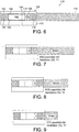
- a preferred embodiment provides a smoking article 110 comprising a tobacco rod 112 and a filter 114 connected with the tobacco rod 112 by a tipping paper 116.
- the filter 114 comprises a first filter segment 118 at an upstream end portion 120 of the filter 114, a mouthpiece filter segment 122 at downstream end portion 124 of the filter 114, and a flow restricting ("restrictor") filter segment 126 situated between the first and mouthpiece filter segments 118 and 122.
- filter segments 118 and 122 are low particulate efficiency filter segments preferably constructed from cellulose acetate tow of 8.0 denier per filament or greater and 35,000 total denier or less, for example.
- the flow restricting filter segment 126 comprises an annular partition 128 that defines an orifice (or flow restriction) 130 of reduced diameter.
- the flow restricting filter segment 126 also includes a tubular body portion 132 in downstream relation to the annular partition 128.
- the tubular body portion 132 includes a plurality of elongate holes 134 that are circumferentially disposed about the tubular body segment portion 132.
- the flow restricting filter segment further comprises a second upstream tubular body portion 136 that spaces the flow restriction 130 a predetermined distance apart from the first filter segment 118, preferably approximately 1 millimeter (mm) to approximately 6 mm, preferably approximately 1 mm to 3 mm.
- a ventilating zone 140 is established with a first row (and optionally second and possibly third rows) of ventilation holes through the tipping paper 116.
- the holes 134 provided about the circumference of the flow restricting filter segment 126 are overlapped by (superposed by) at least some of the ventilation holes at the ventilating zone 140 so that air may be drawn through the ventilation holes at zone 140 and through the flow restricting filter segment and into cavity 146 defined between the flow restriction 130 and the mouthpiece filter segment 122.
- the ventilating zone 140 is located near or adjacent to the restriction 130 and spaced from the mouthpiece filter 122 so that air drawn through the ventilation zone 140 is allowed to mix with the mainstream smoke before arriving at the mouthpiece filter 122.
- the distance between the ventilation zone 140 and the mouthpiece filter 122 is at least 5 mm or in the range of 5 mm to 12 mm.
- the ventilation zone 140 and the holes 134 in the flow restricting filter segment 126 achieve a ventilation level of the smoking article of at least 25% and more preferably at least 50% to 90%.
- Fig. 2 it may be desirable to provide several ventilating zones 140, 140' at locations in superposing relation to the holes 134 provided in the flow restricting filter segment 126 so as to achieve the more elevated ventilation levels.
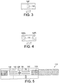
- the partition 128 that establishes the flow restriction 130 may be frustoconical and convergent either into or away from the direction of flow of mainstream smoke passing therethrough (as indicated by the arrows in Figs. 3 and 4 ). Furthermore, they may comprise a pair of partitions 128a'and 128b' that are arranged internally within the flow restricting filter segment so as to provide end to end symmetry for the flow restricting filter segment.
- a filter component having end to end symmetry facilitates high speed filter rod making in that the component works the same whether or not the rod making machine orients one end of the component first or reverses it.
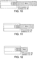
- an alternate embodiment of the present invention includes a flow restricting filter segment having end to end symmetry by reason of the first tubular body portion 132 of the flow restricting filter segment 126 being of equal length with the second, upstream tubular body portion 136 of the flow restricting filter segment 126.
- the second upstream tubular body portion 136 includes a plurality of holes 142 about its circumference in same fashion as holes 134 are disposed about the circumference of first downstream tubular body portion 132.
- Figure 5 also provides opportunity to define a second zone X of ventilation upstream of the restriction 130 in addition to or in lieu of ventilation zone 140 as provided in the preferred embodiment.
- a preferred embodiment provides a smoking article 110 comprising a tobacco rod 112 and a filter 114 connected with the tobacco rod 112 by a tipping paper 116.
- the filter 114 comprises a first filter segment 118 at an upstream end portion 120 of the filter 114, a mouthpiece filter segment 122 at downstream end portion 124 of the filter 114, and a flow restricting filter segment 126 situated between the first and mouthpiece filter segments 118 and 122 and preferably adjacent the first, upstream filter segment 118.
- the flow restricting segment 126 preferably includes one or more flow restriction passages 130 there through.
- filter segments 118 and 122 are low particulate efficiency filter segments preferably constructed from less densely packed, large diameter fiber cellulose acetate tow of approximately 5.0 denier to approximately 15.0 denier per filament (dpf), such as 8 dpf, and approximately 10,000 total denier (td) to approximately 50,000 td, such as 35,000 td.
- a relatively short flow restricting filter segment 126 (hereinafter, restrictor disc) is adjacent the first upstream filter plug 118 of a length of approximately 3 mm to 10 mm, more preferably approximately 3 mm to 7 mm in length.
- a central cavity 146 within the filter 114 is defined at least in part by a tubular filter segment 148, such as a cylindrical cellulosic tube and by the spaced apart relation of the mouthpiece filter 122 and the restrictor disc 126.
- a ventilation zone 140 is provided at a location along the cavity 146, which location is preferably downstream of the restrictor segment 126 and spaced apart from the mouthpiece segment 122.
- the tubular filter segment 148 is preferably constructed from a relatively heavy filter plug paper or other material such as a hollow cellulose acetate tube.
- the ventilation zone 140 comprises a plurality of ventilation holes which extend through the tipping paper 116 and optionally through the tubular filter segment 148. If the tubular filter segment 148 is constructed of paper, it is preferred that the ventilation holes extend through the tubular segment 148. In either case, this arrangement facilitates the use of online laser perforation techniques to provide ventilation holes during the manufacture of the smoking article 110. Other techniques may be used to create the ventilation zone 140 such as using off-line, pre-perforated tipping paper, mechanical perforation, electrostatic perforation and other techniques.
- a desired degree of ventilation (approximately 70%) is maintained throughout the puff count.
- Figs. 10-12 which are not in accordance with the invention, in contrast, when ventilation holes are placed upstream of the restriction, ventilation tends to drop as one progresses through the puff count.
- Table 1 Remainder of Tobacco Rod Restrictor Upstream of Ventilation Restrictor Downstream of Ventilation 50 mm RTD (mm H 2 O): 101 RTD (mm H 2 O): 110 30 mm RTD (mm H 2 O): 100 RTD (mm H 2 O): 109 10 mm RTD (mm H 2 O): 99 RTD (mm H 2 O): 106
- a cigarette having an upstream restrictor 130 with downstream ventilation 140 can provide various effects during smoking. For example, as flow rate of a puff increases, pressure drop at the restrictor increases more rapidly compared to a conventional CA filter. Thus, the restrictor works in this configuration as a limiter on the extent to which a smoker may attempt to draw harder on a smoking article during a puff.
- having the ventilation zone 140 downstream of the restrictor orifice 130 decouples their respective functionalities (ventilation levels and RTD, respectively) such that a cigarette designer may adjust RTD by changing the size of the restrictor orifice 130 essentially without impacting ventilation levels already established at the ventilation zone 140 and vice versa.
- a smoking article 110 comprising a tobacco rod 112 and a filter 114 connected with the tobacco rod by a tipping paper 116.
- the filter comprises a first filter segment 118 constructed from cellulose acetate tow at an upstream end portion of the filter, a mouthpiece filter segment 122 constructed from cellulose acetate tow at a downstream end portion of the filter, and a restrictor disc 126 situated between the first and mouthpiece filter segments 118 and 122, and preferably downstream of and adjacent to the first filter segment 118.
- the cavity 146 within the filter is defined at least in part by a preferably spiral wound paper tube 148 that preferably extends the whole length of the filter and is sufficiently strong to be self-sustaining, yet thin enough to accommodate on-line laser perforation.
- the cavity 146 is further defined by the spaced apart relation of the mouthpiece filter 122 and the restrictor disc 126.
- the outer annulus of the restrictor disc preferably has a sliding fit with the inner surface of paper tube 148.
- a ventilation zone 140 is provided at a location along the cavity 146, which location is preferably downstream of the restrictor segment 126 and spaced apart from the mouthpiece segment 122.
- the tube 148 can be made using other materials or other forming techniques such as molding or extruding the tube or forming a tube with a longitudinal seam.
- the filter segments 118 and 122 have low particulate efficiency and are constructed as previously described.
- a smoking article 110 comprising a tobacco rod 112 and a filter 114 connected with the tobacco rod by a tipping paper 116.
- the filter 114 comprises a first filter segment 119 constructed from carbon on tow at an upstream portion of the filter 114, a second filter segment 118 constructed from cellulose acetate tow downstream of the first filter segment 119, a mouthpiece filter segment 122 constructed from cellulose acetate tow at a downstream end portion of the filter, and a restrictor disc 126 situated between the second and mouthpiece filter segments 118 and 122.
- the outer annulus of restrictor disc 126 is preferably slightly frustoconical to facilitate plunging of restrictor disc 126 along tube 148 from left to right, as shown in Fig. 14 .
- a cavity 146 extends from the mouthpiece filter 122 to the flow restriction 130 and a ventilation zone 140 communicates with the cavity 146 at a location spaced from the mouth-piece plug 122.
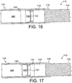
- FIG. 15 another embodiment provides a smoking article 110 comprising a tobacco rod 112 and a filter 114 connected with the tobacco rod by a tipping paper 116.
- the layout of the filter 114 is like that of the embodiments described above in reference to Fig. 14 , except that the restrictor disc 126 preferably is symmetrical or has end-to end symmetry so that the restrictor disc can be reversed without affecting its performance.
- the disc 126 has beveled edges 123, 123' to facilitate sliding.
- This version of the restrictor disc 126 may be used in the filter layout described with reference to Figs. 13 , 16, and 17 as well.
- embodiments provide a smoking article 110 comprising a tobacco rod 112 and a filter 114 connected with the tobacco rod by a tipping paper 116.
- the filters 114 are like those of the embodiments described with reference to Figs. 13 and 14 , respectively, but without the mouthpiece filter segment 122, so that impaction and other filtration effects are further minimized.
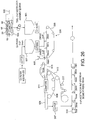
- Fig. 18 illustrates an embodiment of a process whereby 2-up filter rods including a flow restrictor device are constructed and then fed into a tipping machine to form smoking articles.
- Fig. 18A illustrates a double length (2-up) paper filter tube 148' and a double length (2-up) cellulose acetate mouthpiece segment 122'.
- the double length cellulose acetate segment 122' is plunged or otherwise placed centrally in the double length paper filter tube 148', as illustrated in Fig. 18B .
- Restrictor discs 126, 126 are plunged or otherwise placed into position in spaced-apart relation to opposite ends of the 2-up segment 122' by sliding into opposite ends of the tube 148', for example, using plungers 127, as illustrated in Fig.
- One-up first filter segments 118, 118 are then plunged or otherwise placed into place by sliding into opposite ends of the tube 148' adjacent the restrictor discs 126, 126, for example, using plungers 127, as illustrated in Fig. 18D .
- the resulting double length filter rod is inserted between two spaced apart tobacco rods 112, 112 and secured with tipping paper 116, as illustrated in Fig. 18E .
- Optional laser perforation 140 takes place and then the 2-up cigarettes are severed, as shown in Fig. 18F . All of these operations can be carried out using high speed filter rod and cigarette making machinery.
- a two-up mouthpiece filter segment 122 is first disposed at the central location of the two-up tube 148' and the restrictor plugs 126 are set in place. Thereafter, one-up segments 118 and then the one-up carbon on tow segment 119 are plunged or otherwise placed on opposite sides adjacent the restrictor plugs.
- preferred dimensions for an 83 mm smoking article include, for example, a filter length of 27 mm, comprising a paper tubing 27 mm in length, a mouth end filter segment length of 7 mm, ventilation holes 12 mm from the mouth end of the smoking article, a restrictor disc length of 5mm length separated from the mouth end segment by a 5 mm long cavity, a cellulose acetate (CA) tow segment length of 2.5 mm upstream of the restrictor disc, and a carbon on tow (COT) filter segment length of 7 mm upstream of the CA segment.
- a filter length of 27 mm comprising a paper tubing 27 mm in length, a mouth end filter segment length of 7 mm, ventilation holes 12 mm from the mouth end of the smoking article, a restrictor disc length of 5mm length separated from the mouth end segment by a 5 mm long cavity, a cellulose acetate (CA) tow segment length of 2.5 mm upstream of the restrictor disc, and a carbon on tow (COT) filter segment length of
- the ventilation zone 140 is established with a first row (and optionally second and possibly third rows) of ventilation holes through the tipping paper 116 and filter tube 148'. Accordingly, air is preferably drawn through the ventilation holes of ventilation zone 140 and into the cavity 146 defined between the flow restriction 130 and the mouthpiece filter segment 122.
- the ventilation zone 140 is located near or adjacent to the flow restriction 130 and spaced from the mouthpiece filter 122 so that air drawn through the ventilation zone 140 is allowed to mix with the mainstream smoke before arriving at the mouthpiece filter 122.
- the distance between the ventilation zone 140 and the mouthpiece filter 122 is at least 5 mm or in the range of 5 mm to 20 mm.
- the ventilation zone 140 achieves a ventilation level of the smoking article of at least 25% and more preferably at least 50% to 90%, e.g., 60%, 70%, or 80%.
- the restrictor disc 126 may comprise an impermeable partition (transverse wall) having one or more orifices therein, that establishes the flow restriction 130, with the restriction specifically in the form of an orifice of reduced diameter.
- the partition can be perpendicular to the longitudinal axis of the smoking article or frustoconical and convergent either into or away from the direction of flow of mainstream smoke passing therethrough.
- the restrictor disc 126 may be configured to provide end to end symmetry.
- a filter component having end to end symmetry facilitates high speed filter rod making in that the component works the same whether or not the rod making machine orients one end of the component first or reverses it.
- a restrictor disc 126 having end to end symmetry has tubular body portions of equal length on opposite sides of a transverse wall (partition). By such arrangement manufacture of the filter is facilitated by the end to end symmetry of the restrictor disc 126.
- a zone of ventilation may be located upstream of the flow restriction 130 in addition to ventilation zone 140 as provided above.
- Manufacture of the smoking articles 110 in accordance with the present disclosure may be facilitated with the use of pre-perforated tipping paper.
- the flow restriction 130 is sized to contribute sufficient pressure drop such that the smoking article 110 presents a resistance to draw of at least 40 mm water or greater, preferably in the range of 50 mm to 100 mm water.
- the partition (transverse wall) has a diameter of approximately 7.0 mm to 8.0 mm and more preferably approximately 7.4 mm to 7.8 mm wherein the partition preferably has one or optionally, more than one orifice of a diameter of about 0.5 mm to about 1.0 mm and more preferably about 0.5 mm to 0.7 mm. Since the pressure drop of the restrictor component depends on the open area, multiple orifices can also be used. For example, in one embodiment there are two orifices in the partition of 0.5 mm diameter each.
- the restrictor disc 126 may be constructed of paper, a plastic, polymer or a metal and more preferably made of a paper product or a biodegradable plastic/polymer or other suitable material having biodegradability properties.
- the restrictor disc 26, in the embodiments shown in Figs. 6 and 13-17 is small and the non-biodegradable content of the filter is minimized.
- the flow restriction 130 and the mouthpiece filter 122 are spaced apart sufficiently to reduce impaction of particulate smoke components upon the upstream face of the mouthpiece filter 122.
- the flow restriction 130 is spaced approximately 4 mm to 20 mm from the mouthpiece filter 122, more preferably approximately 6 mm to 10 mm.
- the filter preferably may be constructed from simple combining techniques typically used in the industry for manufacturing cigarettes at high speeds. Additionally each embodiment includes tubular support about the cavity 146 so as to provide desired firmness throughout length of the filter 114. Furthermore, the embodiments provide the necessary amount of resistance to draw while maintaining the desired degree of high ventilation throughout the puff count. The latter attribute is achieved by placement of the ventilation zone 140 downstream of the flow restriction 130. Furthermore, placing the ventilation along cavity 146 assures mixing of air drawn into the filter 114 through the ventilation zone 140 with mainstream smoke drawn from the tobacco rod 112. In one tested embodiment, uniform stain patterns appeared at the buccal end of the mouthpiece filter 122, which is indicative of good mixing.
- a consistent degree of ventilation e . g ., 50% to 90%, preferably about 70% is preferably maintained throughout the puff count as shown in Figs. 7-9 and Table 1.
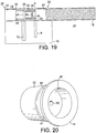
- a smoking article 10 comprising a tobacco rod 12 and a filter 14 connected with the tobacco rod 12 by tipping paper 16 is shown.
- the filter 14 comprises an optional filter segment 24 of low particulate efficiency at an upstream end portion 20 and an optional mouthpiece filter segment 22 of low particulate efficiency at the downstream end 25 of the filter 14.
- a flow restricting filter segment 26 (or component) is situated upstream of a ventilation zone 40 that communicates with a cavity 46.
- a smoking article 10 includes a flow restricting filter segment 26 received in an air transmissive tubular segment 30. During manufacturing operations, a T-restrictor insert 18 is plunged into the upstream end portion of the tubular segment 30.
- the tubular segment 30 is constructed from cellulose acetate tow (sometimes referred to as a hollow acetate tube or HAT) and the T-restrictor insert 18 includes a transverse disc shaped wall 45 with one or more openings 60 therein and a longitudinal tubular section 32 extending therefrom having a length of about 3 mm to about 10 mm, more preferably about 3 mm to about 7 mm in length.
- the T-insert includes an outer rim 33, which is wider than the tubular section 32 such that the insert 18 looks T-shaped in a side view.
- a central cavity 46 within the filter 14 is defined at least in part by the tubular segment 30 and optionally, in part by the space enclosed by the tubular section 32 of the restrictor insert 18.
- a ventilation zone 40 communicates with the cavity 46 at a location downstream of the restrictor insert 18.
- the tubular segment 30 is preferably constructed from a hollow acetate tube (HAT) and is preferably air permeable (low density) so that ventilation air may be drawn through ventilation holes 75 into the cavity 46 during a puff.
- HAT hollow acetate tube
- Other low density, low filtration materials can also be used to construct the tubular segment 30.
- mainstream smoke is drawn through an orifice 60, illustrated in Figure 20 , in the transverse smoke impermeable wall (disc) 45 of the T-restrictor 18, through the cavity 46, where it is mixed with ventilation air that is drawn into the cavity 46 via the ventilation zone 40.
- the orifice 60 is preferably a constant diameter. In another embodiment, the diameter of the orifice 60 varies along the length of the orifice.
- the ventilation zone 40 comprises a plurality of ventilation holes 75 arranged in one or more circumferential rows, which extend through the tipping paper 16 and optionally/partially into or through the tubular segment 30.
- This arrangement facilitates the use of off-line laser perforation techniques to provide ventilation holes 75.
- Other techniques may be used to create the ventilation zone 40 such as using on-line, laser perforation, mechanical pin perforation techniques, electrostatic perforation and other techniques.
- the ventilation holes 75 in the tipping paper 16 allow atmospheric air to be drawn into the ventilation zone 40, through the tubular segment 30, and into the cavity 46.
- perforations need not be made in the tubular filter segment 30 because the material is air permeable.
- the ventilation zone 40 and the tubular filter segment 30 achieve a ventilation level of the smoking article of at least about 25% and more preferably at least about 50% to about 90%.
- Fig. 20 is an illustration of the T-restrictor insert 18 shown in Fig. 19 .
- the T-restrictor insert 18 includes a smoke impermeable transverse wall 45 with at least one orifice 60 formed therein.
- the transverse wall 45 is at an intermediate location along the tubular portion 32 of the T-restrictor insert 18.
- the outer wall of the tubular portion 32 includes a step 43 which forms a depression 41 to receive material of the HAT 26 and lock the restrictor insert 18 in place.
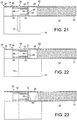
- Fig. 21 is an illustration of a smoking article 10 including a filter 14 having a T-restrictor insert 18 plunged into one end of the air transmissive tubular portion 30.
- hot melt adhesive 6 is applied transversely on the filter paper or plug wrap to form a circumferential seal along the outer edge of the rim 33 and to join the T-restrictor insert 18 with first filter segment 24 and the HAT segment 30. Such arrangement further prevents mainstream smoke from being drawn around the outer edges of T-restrictor insert 18.
- Fig. 22 is an illustration of a smoking article 10 including a filter 14 having an upstream filter segment 24 and an upstream cavity 85.
- the filter includes a tubular segment 30 comprising an air transmissive material and a T-restrictor insert 18 plunged into the upstream end of the tubular segment 30.
- the T-restrictor insert 18 includes an orifice 60 in the transverse wall 45.
- the upstream cavity 85 helps prevent blockage of the orifice 60 during smoking.
- the smoking article 10 includes a filter 14 with an upstream filter segment 24 having central recesses 86 extending into each end.
- the recesses 86 are axially aligned with the orifice 60 of the T-restrictor insert 18 that is plunged into the tubular portion 30 as in Figs. 21-22 .
- the recess 86 adjacent the restrictor insert 18 prevents blockage of the orifice 60 from accumulation of tar particles and/or condensates during smoking.
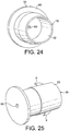
- Fig. 24 is an illustration of the T-restrictor insert 18, shown in Figs. 21-22 , for use in a filter 14.
- the T-restrictor insert 18 is a single piece including a hollow tubular portion 32 and a transverse wall (or disc) 45.
- the transverse wall 45 has an orifice 60 located adjacent a central point in the transverse wall 45 of the T-restrictor insert 18, although other positions may be selected and more than one orifice 60 may be provided in the wall 45.
- the elongated portion 32 of the T-restrictor 18 forms a channel with dimensions of about 3 mm to about 9 mm in diameter and about 7 mm to about 10 mm in length.
- the tubular portion 32 fits snuggly inside the tubular segment 30, which is preferably a hollow acetate tube.
- the transverse wall 45 is preferably sized to cover a substantial portion of the end of the hollow acetate tube once the tubular portion 32 has been inserted therein.
- the T-restrictor insert 18 can include barbs 9.
- the barbs 9 anchor the T-restrictor insert 18 inside the hollow acetate tube (HAT) when the elongated portion 32 of the T-restrictor insert 18 is inserted into the HAT.
- the outer diameter of the rim 33 is less than that of the original diameter of the tubular segment 30 prior to filter rod making operations.
- the diameter of the rim 33 is smaller than the pre-determined diameter of the cigarette to be made.
- the circumference of the rim 33 is preferably 1% to 10% smaller, e . g ., approximately 23.9 mm or less in the example.
- the original diameter or the HAT segment 30 is slightly oversized so that it may be uniformly compressed into the desired diameter ( e . g . 24.1 mm), and held in place by the plug wrap during filter making operations. Because the rim 33 is of lesser diameter, the T-restrictor insert 18 passes through the garniture of a filter rod making machine without snagging.
- the T-restrictor insert 18 is a single piece that is injection molded.
- the T-restrictor insert 18 is preferably made of a plastic, metal, cellulosic material, and/or composite of a plastic and starch. Suitable plastics include, without limitation, polypropylene, polyethylene, polystyrene, nylon, polysulfone, polyester, polyurethane, and combinations thereof.
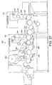
- pairs of HAT segments 30 are each respectively situated along flutes of a drum 504 between opposing pairs of 2-up T-restrictor inserts 18, 18' and are all pushed together so that a pair of 2-up HAT restrictor assemblies are established on each flute, which assemblies are each 26 mm long.
- the pairs are then fed or placed into a first hopper 501 of an upstream section 506 of a double-action plug-tube combiner (DAPTC) combiner. More preferably, this insertion step may be performed on drums just below the hopper 501.
- the 2-up HAT restrictor assemblies are separated and fed in spaced apart relation onto an endless feed belt 505 of a Molins double-action plug-tube combiner or other combining machine of similar capabilities.
- continuous cellulose acetate, low particulate efficiency, filter rods are produced and cut into a plurality of CA 6-up/84 mm long rods, which are fed or placed into a second hopper 507 of the DAPTC combiner.
- the 6-up rods are further cut and sorted into 2-up/14 mm segments (corresponding to a 2-up version of the upstream filter segment 24 of Fig. 19 ) and placed in alternating relation to the restrictor assemblies on the feed belt 505.
- a rotating spacer drum 508 establishes a continuous, closed-up procession 515 of the alternating 2-up restrictor assemblies and 2-up CA segments in mutually abutting, end to end relation with one after another. Downstream of the rotating spacer drum 508, the procession is transferred onto a ribbon of plug wrap 513.
- a garniture belt 509 draws both the procession 515 and the plug wrap 513 through a garniture 511 whereat the plug wrap 513 is wrapped about the procession of plugs 515 so as to form a continuous filter rod 521.
- one or more glue guns 517 apply a desired pattern of glue continuously and/or at spaced locations along the ribbon of plug wrap 513 to retain filter rod 521 in its final form.
- the rims 33 of the T-restrictor inserts 18 are undersized relative to the target diameter of the filter rod 521, they pass through the garniture 511 and remain set in place at spaced location along the rod 521.
- a cutter 517 severs the continuous rod 521 so as to repetitively form a 6-up restrictor/upstream segment assembly (rod) 519.
- the 6-up rod 519 preferably comprises the following segments from one end to the other: a 1-up/7 mm CA segment at one end of the rod 521; a first 26 mm/2-up restrictor assembly segment; a14 mm/2-up CA segment; a second 26 mm/2-up restrictor assembly segment; a second 14 mm/2-up CA segment; a third 26 mm/2-up restrictor assembly segment; and a second, 1-up/7 mm at the opposite end of the rod.
- the 6-up rods 519 are then fed or placed into a first hopper 170 of a dual hopper max tipping machine or a machine of similar capabilities.
- the 6-up/120 mm rods 519 are then cut into three, 2-up rods 521 at drum 222, then graded at drum 224, aligned at drum 226, whereupon each is cut centrally and spaced apart into opposing pairs of sub-assemblies along each flute of the drum 232.
- Each sub-assembly comprises a 1-up/7 mm CA segment (corresponding to the upstream segment 24 in Fig. 12 ), a T-restrictor insert 18 and a 1-up HAT segment, whose open end portion is directed inwardly along the respective drum flute.
- the pairs of sub-assemblies are then spaced apart sufficiently to receive 2-up/14 mm CA plugs 622 therebetween.
- the 2-up plugs 622 each correspond to a 2-up version of the downstream (mouthpiece) filter segments 22 shown in Fig. 19 .
- the 2-up plugs 622 are preferably constructed from similar cutting, grading and aligning operations on 6-up 84 mm long filter rods at drums 242, 244 and 246 of the DHMAX represented in Fig. 27 , with further cut, grade and align operations occurring at or about the drum 248.
- the plugs are brought together at drum 250 to form a complete 2-up filter structures 525, which are then fed in between pairs of spaced apart tobacco rods 527, as illustrated in Fig. 29 , and wrapped with tipping paper 529 in accordance with the usual tipping operations of a Dual Hopper Max to form a completed 2-up cigarette structure 531.
- the 2-up cigarette structure 531 is severed and the cigarettes are aligned at drum 264 whereupon they are directed to a packer 266 from whence they go to a cartoner 268 and to a case packer 270.
- Hollow acetate filter plugs may be produced in continuous fashion from a tubular filter rod maker such as the maker as described in US 3 637 447 to Berger et al. Subsequent combining and tipping operations may be executed on a Molins double-action plug-tube combiner (DATPC).
- the tobacco rods are constructed on a conventional cigarette rod making machine (such as a Molins Mark 9 tobacco rod maker) wherein cut filler (preferably blended) is air formed into a continuous rod of tobacco on a traveling belt and enwrapped with a continuous ribbon of plug wrap which is then glued along its longitudinal seam and sealed with adhesive.
- the output of the tobacco rod maker is then cut and delivered to a tipping machine such as a Hauni Dual Hopper Max that has been modified to execute the combining and tipping operations described herein.
- a tipping machine such as a Hauni Dual Hopper Max that has been modified to execute the combining and tipping operations described herein.
- the flow restriction segment 26' includes a torturous, preferably spiral, channel 80 in filter 14 to introduce the desired resistance to draw.
- the spiral smoke flow pattern through the restrictor 26' can reduce gas vapor phase of mainstream smoke by diffusion, absorption/adsorption, and/or can reduce larger or heavier smoke particles by centrifugation and impaction.
- a spiral flow channel 80 opens into a large central cavity 46 and is preferably located upstream of the ventilation zone 40 of the filter 14.
- the channel 80 is formed in an impermeable material.
- the spiral channel 80 is made of a material selected from the group consisting of high density polyethylene, compressed cellulosic materials, and combinations thereof. Regular wrapping paper, carbon paper, or carbon on tow is wrapped around the segment 26' to enclose the spiral flow path for smoke.
- the spiral channel 80 has an inner diameter of about 0.30 mm to about 1.5 mm and a length of about 10 mm to about 200 mm.
- flavorants or colorants can be added to the material surrounding the spiral channel 80.
- flavorants include licorice, sugar, isosweet, cocoa, lavender, cinnamon, cardamom, apium graveolens, fenugreek, cascarilla, sandalwood, bergamot, geranium, honey essence, rose oil, vanilla, lemon oil, orange oil, mint oils, cassia, caraway, cognac, jasmine, chamomile, menthol, cassia, sage, spearmint, ginger, coriander, coffee and the like.
- smoke is drawn through the channel 80 during a puff and the channel 80 acts as a flow restrictor.
- the channel 80 acts as a flow restrictor.
- a desired pressure drop across the segment can be achieved.
- the channel 80 leads to a cavity 46 within the filter 14 that is defined at least in part by a tubular segment 30, such as a cellulosic tube extending from end to end of filter 14.
- a ventilation zone 40 is introduced downstream of the spiral channel 80. Perforations in the tipping paper 16 and the cylindrical tubular filter segment 30 provide for ventilation and the tubular segment 30 may optionally be constructed of fibers so as to be air-permeable.
- the spiral flow channel 80 can be finely tuned to selectively allow only a particular range or size of smoke, for example, semi-volatile enriched smoke aerosol particles, to pass to the cavity 46. Both gas phase and particulate phase smoke can be reduced, but preferably, the flavor rich semi-volatiles are allowed to remain in the smoke.
- a carbon paper or sheet material containing adsorbents is wrapped around the spiral segment, the gas phase components of the smoke being drawn through the filter channel may diffuse out or the filter and/or contact the paper longer resulting in capture of targeted constituents. The heavy or large aerosol particles experiencing centrifugation or impaction action can also be trapped.
- the materials, for example, paper foam or starch based plastics, used to form the segment 26' can be chosen or treated to enhance a particular filtration selectivity or to deliver flavor.
- the material can be treated with a waxy or oil material to enhance removal of non-polar component or treated with glycerin to enhance removal of polar compounds.
- the spiral flow restrictor segment could be used to remove any fine carbon particles that may have become entrained in the mainstream smoke, commonly referred to as carbon breakthrough.
- This functionality may be enhanced by including an agent along the wrap adjacent the spiral channel that has an affinity for the carbon particles.
- the agent can be a sticky or entraining substance or material such as wax, glycerin, or other carbon-catching agent.
- another embodiment comprises a smoking article constructed according to the same layout such as described with respect to the embodiments described in Figures 6 and 13-17 , except for there being a restrictor segment 726 having a central channel 727 whose diameter and length are selected to impart a desired level of RTD as previously described.
- the channel 727 is flared 728 at its ends 729 so as to avoid build-up of particles and condensates.
- the first filter segment 118 may be provided with recesses 119, which when positioned adjacent the end 729 of the channel 727 help further abate build-up at channel 727.
- the restrictor segment 26 may include a filter plug 826 having at least one spiral groove 827 formed therein.
- the at least one spiral groove 827 acts as an orifice through which smoke can pass.
- the desired level of pressure drop (RTD) is a function of the channel 827 diameter and length of the channel 827, so the degree of spiral is adjusted to provide requisite pressure drop for a particular channel diameter.
- the restrictor segment 26 may instead comprise a cellulose acetate filter plug 90 of low particulate efficiency filtering material coated or treated about an annular zone 95 on one or optionally both ends so as to define an orifice 30 at an untreated zone 97.
- a small portion 97 of the end of the filter plug is left uncoated or untreated so as to form an orifice through which mainstream smoke may flow.
- the occlusive agent is an extra amount of triacetin that is applied to one end so as to render the annular region 95 impermeable to smoke.
- heat treatment is applied to the region 95 to render it impermeable to smoke.
- the coating or treatment is not applied in an annular zone adjacent the periphery of the plug so as to allow slight compression to occur in this region of the plug when passing through a garniture or a rod-making machine and being wrapped with plug wrap.
- the region 95 could instead be covered with an impermeable ring of paper of film-forming agent or adhesive.
- the restrictor segment 26 includes a low particulate efficiency cellulose acetate filter plug upstream of the ventilation zone 40.
- the cellulose acetate filter plug 90 is coated or treated about an annular zone 95 on one end so as to define an orifice 30 at an untreated zone 97.
- a small portion 97 of the end of the filter plug is left uncoated or untreated so as to form an orifice through which smoke may flow.
- the coated end is located at a downstream of the filter segment 90.
- the layout of the smoking article in Figs. 34 and 35 is arranged to perform in like manner to those of Figs. 6 , and 13-17 .
- CO levels tend to be higher in the low permeability wrappers for reducing production of side stream smoke during smolder; in double wrap papers for reducing side stream smoke; and in double wrap papers for reducing the tendency of certain blends and/or flavor systems to spot at random locations along the tobacco rod.
- These tendencies can be alleviated in any cigarette layout employing such wrappers by combining the so wrapped tobacco rod with a restrictor filter as taught herein.
- the filter achieves significant smoke constituent reductions without the taste penalty associated by Americans with carbon-filters.
Claims (13)
- Article à fumer (110) comprenant :une tige de tabac (112) adaptée pour produire de la fumée principal ;un filtre (114) fixé à ladite tige de tabac (112), ledit filtre ayant une partie d'extrémité amont et une partie d'extrémité aval, ledit filtre (114) comprenant :une cavité centrale unique (146) située entre ladite extrémité amont et ladite extrémité aval et définie par une périphérie interne d'un segment tubulaire (148) sélectionnée à partir du groupe constitué d'un tube cellulosique, d'un tube creux en acétate, du carbone sur l'étoupe, du papier carbone, et de combinaisons de ceux-ci ;un segment de limitation de l'écoulement (126) du matériau imperméable à la fumée situé en amont de ladite cavité (146) et incluant au moins un passage d'écoulement (130) à travers celui-ci pour délivrer de la fumée principale à la cavité et produire une partie substantielle d'une résistance prédéterminée au tirage ; et
une zone de ventilation (140) à un emplacement le long de ladite cavité (146) et en aval dudit segment de limitation de l'écoulement (126) pour mélanger l'air atmosphérique avec la fumée principale. - Article à fumer selon la revendication 1, dans lequel ledit filtre (114) et la tige de tabac (112) sont fixés avec du papier manchette (116), ladite zone de ventilation (140) incluant une rangée de perforations à travers le papier manchette.
- Article à fumer (110) selon la revendication 1 ou 2, dans lequel la résistance prédéterminée au tirage dudit article à fumer (110) est d'environ 40 millimètres d'eau ou plus.
- Article à fumer (110) selon la revendication 1, 2 ou 3, dans lequel ledit article à fumer (110) inclut une première bout-filtre (118) en amont dudit segment de filtre limitant l'écoulement (126) et une deuxième bout-filtre (122) à l'extrémité buccale dudit article à fumer, dans lequel ledit premier segment de bout-filtre (118) et ledit deuxième segment de bout-filtre (122) comprennent un étoupe d'acétate de cellulose ayant une faible efficacité de filtration.
- Article à fumer (110) selon l'une quelconque des revendications 1 à 4, dans lequel ledit passage d'écoulement (130) est un conduit ouvert allongé ayant une configuration tortueuse ou droite, telle qu'une configuration droite et une longueur d'environ 7 mm à environ 10 mm.
- Article à fumer (110) selon la revendication 5, dans lequel ledit canal tortueux a une configuration hélicoïdale et/ou courbe, un diamètre interne d'environ 0,30 mm à environ 1,5 mm, et une longueur d'environ 10 mm à environ 200 mm.
- Article à fumer (110) selon l'une quelconque des revendications 1 à 6, dans lequel ledit segment de limitation de l'écoulement (126) est formé à partir d'un matériau choisi à partir de polyéthylène haute densité, polypropylène, nylon, matériau cellulosique comprimé, et/ou combinaisons de celui-ci et/ou ledit segment de limitation de l'écoulement est au moins partiellement entouré par des tubes cellulosiques, du papier de carbone, de l'acétate de cellulose et/ou du carbone sur l'étoupe.
- Article à fumer (110) selon l'une quelconque des revendications 1 à 7 comprenant en outre un segment de filtre contenant un sorbant (119) en amont du segment de limitation de l'écoulement (126).
- Article à fumer (110) selon l'une quelconque des revendications 1 à 8, dans lequel ledit segment de filtre limitant l'écoulement (126) inclut un élément de verrouillage engageant ledit segment tubulaire et/ou ledit segment tubulaire est coextensif à la longueur du filtre.
- Article à fumer (110) selon l'une quelconque des revendications 1 à 9, dans lequel ledit segment de limitation de l'écoulement (126) du matériau imperméable à la fumée est un segment filtrant en acétate de cellulose ayant un revêtement d'agent occlusif recouvrant partiellement au moins une extrémité dudit segment de filtre en acétate de cellulose.
- Article à fumer (110) selon l'une quelconque des revendications précédentes dans lequel la tige de tabac (112) comprend une enveloppe autour du matériau de tabac, l'enveloppe ayant des bandes substantiellement circonférentielles de poids de base augmenté ou étant une double enveloppe.
- Procédé de fabrication d'un article à fumer (110) comprenant :la fabrication d'un filtre (114) par :
la mise en place d'un premier segment de filtre (118) dans un tube de filtre cylindrique (148) ;la mise en place d'un segment de filtre limitant l'écoulement (126) dans le tube de filtre adjacent audit premier segment de filtre (118), de sorte que ledit filtre inclut en outre une cavité (146) adjacente audit segment de filtre limitant l'écoulement ; etl'établissement d'une zone de ventilation (140) à un emplacement situé le long de ladite cavité (146), ladite zone de ventilation comprenant des perforations à travers ledit tube de filtre ; etla fixation dudit filtre (114) à une tige de tabac (112) avec du papier manchette (116) de telle sorte que ledit segment de filtre limitant l'écoulement (126) soit en amont de ladite cavité (146) de sorte que ladite zone de ventilation (140) est en aval dudit segment de filtre limitant l'écoulement. - Procédé selon la revendication 12, dans lequel ledit filtre (114) est fixé à ladite tige de tabac (112) avec du papier manchette (116) avant la création de la zone de ventilation (140), et en outre dans lequel lesdites perforations se font via ledit tube de filtre (148) et ledit papier manchette.
Priority Applications (1)
| Application Number | Priority Date | Filing Date | Title |
|---|---|---|---|
| PL07732198T PL2007233T3 (pl) | 2006-03-28 | 2007-03-28 | Wyrób do palenia z ogranicznikiem |
Applications Claiming Priority (4)
| Application Number | Priority Date | Filing Date | Title |
|---|---|---|---|
| US78635206P | 2006-03-28 | 2006-03-28 | |
| US85840706P | 2006-11-13 | 2006-11-13 | |
| US90583307P | 2007-03-09 | 2007-03-09 | |
| PCT/GB2007/001144 WO2007110650A1 (fr) | 2006-03-28 | 2007-03-28 | Article a fumer dote d'un limiteur d'ecoulement |
Publications (2)
| Publication Number | Publication Date |
|---|---|
| EP2007233A1 EP2007233A1 (fr) | 2008-12-31 |
| EP2007233B1 true EP2007233B1 (fr) | 2019-08-14 |
Family
ID=38180706
Family Applications (1)
| Application Number | Title | Priority Date | Filing Date |
|---|---|---|---|
| EP07732198.2A Active EP2007233B1 (fr) | 2006-03-28 | 2007-03-28 | Article à fumer doté d'un limiteur d'écoulement |
Country Status (16)
| Country | Link |
|---|---|
| US (2) | US7878963B2 (fr) |
| EP (1) | EP2007233B1 (fr) |
| JP (1) | JP5417166B2 (fr) |
| KR (1) | KR20090008277A (fr) |
| CN (1) | CN101442917B (fr) |
| AU (1) | AU2007231147B2 (fr) |
| BR (1) | BRPI0709264B1 (fr) |
| CO (1) | CO6140007A2 (fr) |
| EA (1) | EA015068B1 (fr) |
| ES (1) | ES2745081T3 (fr) |
| MX (1) | MX2008012396A (fr) |
| MY (1) | MY177466A (fr) |
| NO (1) | NO20084469L (fr) |
| NZ (1) | NZ571453A (fr) |
| PL (1) | PL2007233T3 (fr) |
| WO (1) | WO2007110650A1 (fr) |
Families Citing this family (76)
| Publication number | Priority date | Publication date | Assignee | Title |
|---|---|---|---|---|
| US7987856B2 (en) | 2005-12-29 | 2011-08-02 | Philip Morris Usa Inc. | Smoking article with bypass channel |
| US8240315B2 (en) | 2005-12-29 | 2012-08-14 | Philip Morris Usa Inc. | Smoking article with improved delivery profile |
| KR20090008277A (ko) | 2006-03-28 | 2009-01-21 | 필립모리스 프로덕츠 에스.에이. | 흐름제한장치를 구비한 끽연물품 |
| US8353298B2 (en) | 2006-07-12 | 2013-01-15 | Philip Morris Usa Inc. | Smoking article with impaction filter segment |
| US8424539B2 (en) | 2006-08-08 | 2013-04-23 | Philip Morris Usa Inc. | Smoking article with single piece restrictor and chamber |
| GB0624321D0 (en) * | 2006-12-05 | 2007-01-17 | British American Tobacco Co | Tobacco smoke filter and methods of making the same |
| US8235056B2 (en) | 2006-12-29 | 2012-08-07 | Philip Morris Usa Inc. | Smoking article with concentric hollow core in tobacco rod and capsule containing flavorant and aerosol forming agents in the filter system |
| TW200900014A (en) | 2007-03-09 | 2009-01-01 | Philip Morris Prod | Smoking article filter with annular restrictor and downstream ventilation |
| TW200911138A (en) * | 2007-03-09 | 2009-03-16 | Philip Morris Prod | Smoking articles with restrictor and aerosol former |
| TW200911141A (en) * | 2007-03-09 | 2009-03-16 | Philip Morris Prod | Super recessed filter cigarette restrictor |
| GB0813567D0 (en) * | 2008-07-24 | 2008-09-03 | British American Tobacco Co | Filter for a smoking article |
| EP2253231A1 (fr) * | 2009-05-18 | 2010-11-24 | Philip Morris Products S.A. | Article à fumer avec élément de restriction de flux amélioré |
| US20110083687A1 (en) * | 2009-10-09 | 2011-04-14 | Philip Morris Usa Inc. | Cigarette filter to reduce smoke deliveries in later puffs |
| AR080556A1 (es) | 2009-10-09 | 2012-04-18 | Philip Morris Prod | Diseno de filtro para mejorar el perfil sensorial de articulos para fumar con boquilla de filtro de carbono |
| US8424540B2 (en) * | 2009-10-09 | 2013-04-23 | Philip Morris Usa Inc. | Smoking article with valved restrictor |
| US8905037B2 (en) | 2009-10-15 | 2014-12-09 | Philip Morris Inc. | Enhanced subjective activated carbon cigarette |
| EP2319334A1 (fr) * | 2009-10-27 | 2011-05-11 | Philip Morris Products S.A. | Système de fumage ayant une partie de stockage de liquide |
| ZA200909228B (en) * | 2009-12-23 | 2014-11-26 | Tobacco Res And Dev Inst (Pty) Ltd | Fluid release mechanism |
| US9138016B2 (en) | 2010-03-26 | 2015-09-22 | Philip Morris Usa Inc. | Smoking articles with significantly reduced gas vapor phase smoking constituents |
| GB201104788D0 (en) | 2011-03-22 | 2011-05-04 | British American Tobacco Co | Smoking article |
| US8858889B2 (en) * | 2011-04-11 | 2014-10-14 | Hamilton Sundstrand Space Systems International, Inc. | Contaminate control device |
| GB2490732A (en) * | 2011-05-13 | 2012-11-14 | British American Tobacco Co | Filter for a smoking article |
| GB201110863D0 (en) * | 2011-06-27 | 2011-08-10 | British American Tobacco Co | Smoking article filter and insertable filter unit thereof |
| US20140224268A1 (en) * | 2011-09-09 | 2014-08-14 | Philip Morris Products S.A. | Smoking article filter including polymeric insert |
| EP2753198B1 (fr) * | 2011-09-09 | 2016-08-10 | Philip Morris Products S.a.s. | Filtre d'article à fumer doté d'un élément de restriction de flux et d'une cavité |
| GB201116565D0 (en) * | 2011-09-26 | 2011-11-09 | British American Tobacco Co | Smoking article and method of manufacturing a smoking article |
| US8967155B2 (en) | 2011-11-03 | 2015-03-03 | Celanese Acetate Llc | Products of high denier per filament and low total denier tow bands |
| BR112014013198B1 (pt) | 2011-12-30 | 2020-11-10 | Philip Morris Products S.A | artigo de fumar |
| EP2625975A1 (fr) | 2012-02-13 | 2013-08-14 | Philip Morris Products S.A. | Article de génération d'aérosol avec un élément de refroidissement d'aérosol |
| SG11201403666XA (en) | 2011-12-30 | 2014-07-30 | Philip Morris Products Sa | Smoking article with front-plug and aerosol-forming substrate and method |
| AR089602A1 (es) | 2011-12-30 | 2014-09-03 | Philip Morris Products Sa | Articulo generador de aerosoles para usar con un dispositivo generador de aerosoles |
| EP2625974A1 (fr) * | 2012-02-13 | 2013-08-14 | Philip Morris Products S.A. | Article de génération d'aérosol avec un composant de génération de saveur |
| KR101362616B1 (ko) * | 2012-01-31 | 2014-02-13 | 주식회사 케이티앤지 | 필터 내 연기흐름 속도 증가를 통한 연량감 개선 필터 |
| AR091211A1 (es) | 2012-05-31 | 2015-01-21 | Philip Morris Products Sa | Cilindros saborizados para uso en articulos generadores de aerosol |
| MX347010B (es) * | 2012-06-07 | 2017-04-06 | Philip Morris Products Sa | Artículo para fumar que tiene tabaco de alta densidad. |
| AR091509A1 (es) | 2012-06-21 | 2015-02-11 | Philip Morris Products Sa | Articulo para fumar para ser usado con un elemento de calentamiento interno |
| SG11201500860VA (en) * | 2012-08-06 | 2015-03-30 | Philip Morris Products Sa | Smoking article with mouth end cavity |
| MX363927B (es) * | 2012-08-06 | 2019-04-08 | Philip Morris Products Sa | Metodo para formar articulos para fumar con cavidades de extremo de boca. |
| GB201219540D0 (en) | 2012-10-31 | 2012-12-12 | British American Tobacco Co | A filter for a smoking article |
| CN111972708A (zh) * | 2012-12-31 | 2020-11-24 | 菲利普莫里斯生产公司 | 包括处于中空管中的流量限制器的吸烟制品 |
| HUE045570T2 (hu) * | 2012-12-31 | 2020-01-28 | Philip Morris Products Sa | Eljárás és berendezés dohányzási cikkekhez való szûrõk elõállítására |
| RU2637743C2 (ru) | 2012-12-31 | 2017-12-06 | Филип Моррис Продактс С.А. | Курительное изделие, содержащее ограничитель потока |
| GB2511303A (en) * | 2013-02-27 | 2014-09-03 | British American Tobacco Co | Smoking apparatus |
| GB2511305A (en) | 2013-02-27 | 2014-09-03 | British American Tobacco Co | A smoking device and a component for a smoking device |
| US10190065B2 (en) | 2013-03-15 | 2019-01-29 | Mark E. Koenig | Feed delivery system and method for gasifier |
| US9278814B2 (en) | 2013-03-15 | 2016-03-08 | Mark E. Koenig | Isolation gate |
| PL2978327T3 (pl) | 2013-03-28 | 2019-06-28 | Philip Morris Products S.A. | Wyrób do palenia zawierający element dostarczający aromat |
| CN105357992A (zh) | 2013-07-03 | 2016-02-24 | 日本烟草产业株式会社 | 香烟用过滤嘴和附带过滤嘴香烟 |
| US20150020822A1 (en) * | 2013-07-19 | 2015-01-22 | Altria Client Services Inc. | Electronic smoking article |
| KR101396023B1 (ko) * | 2013-07-19 | 2014-05-16 | 삼성정밀화학 주식회사 | 필터 내 연기흐름 속도 증가를 통한 연량감 개선 필터 |
| RU2664352C2 (ru) * | 2013-08-14 | 2018-08-16 | Филип Моррис Продактс С.А. | Способ и система для обертывания блока сегментов |
| US10172386B2 (en) | 2013-12-31 | 2019-01-08 | Philip Morris Products S.A. | Smoking article including flow restrictor in hollow tube |
| CN106455681B (zh) * | 2014-05-30 | 2020-08-07 | 菲利普莫里斯生产公司 | 带有通风嘴端腔的吸烟制品 |
| RU2671646C1 (ru) * | 2015-05-13 | 2018-11-06 | Джапан Тобакко Инк. | Курительное изделие с фильтром и фильтр курительного изделия |
| TW201703660A (zh) * | 2015-06-23 | 2017-02-01 | 菲利浦莫里斯製品股份有限公司 | 氣溶膠產生物件及製造氣溶膠產生物件之方法 |
| TW201700019A (zh) | 2015-06-30 | 2017-01-01 | 菲利浦莫里斯製品股份有限公司 | 具有改良的熄滅性的菸製品 |
| WO2017055500A1 (fr) * | 2015-09-30 | 2017-04-06 | Philip Morris Products S.A. | Article à fumer à fumée secondaire réduite |
| GB201608928D0 (en) * | 2016-05-20 | 2016-07-06 | British American Tobacco Co | Article for use in apparatus for heating smokable material |
| GB201608931D0 (en) * | 2016-05-20 | 2016-07-06 | British American Tobacco Co | Article for use in apparatus for heating smokeable material |
| AR108880A1 (es) * | 2016-06-27 | 2018-10-03 | Philip Morris Products Sa | Artículo para fumar con ajuste de la eficiencia de ventilación y filtración combinadas |
| US11058147B1 (en) * | 2016-07-29 | 2021-07-13 | Christopher L. Hurley | Freezable smoking pipe with integrated reflective particles |
| GB201700136D0 (en) | 2017-01-05 | 2017-02-22 | British American Tobacco Investments Ltd | Aerosol generating device and article |
| GB201700620D0 (en) | 2017-01-13 | 2017-03-01 | British American Tobacco Investments Ltd | Aerosol generating device and article |
| GB201715924D0 (en) * | 2017-09-29 | 2017-11-15 | British American Tobacco Investments Ltd | A filter unit for a smoking article |
| CA3076302A1 (fr) * | 2017-10-02 | 2019-04-11 | Essentra Filter Products Development Co. Pte. Ltd. | Filtre d'article pour fumeurs |
| GB201720338D0 (en) | 2017-12-06 | 2018-01-17 | British American Tobacco Investments Ltd | Component for an aerosol-generating apparatus |
| JP6864294B2 (ja) * | 2018-04-12 | 2021-04-28 | 株式会社東亜産業 | 電子タバコカートリッジ |
| US11432581B2 (en) | 2018-09-07 | 2022-09-06 | Altria Client Services Llc | Capsule containing a matrix, device with the matrix, and method of forming the matrix |
| US11395507B2 (en) * | 2018-09-07 | 2022-07-26 | Altria Client Services Llc | Filter for an e-vaping device, e-vaping device with the filter, and method of forming the filter |
| CN112804890B (zh) * | 2018-10-05 | 2022-08-30 | 日本烟草产业株式会社 | 吸烟物品的制造方法 |
| EP4183272A1 (fr) * | 2018-10-05 | 2023-05-24 | Japan Tobacco Inc. | Article à fumer |
| BR112021010712A2 (pt) * | 2018-12-20 | 2021-08-31 | Philip Morris Products S.A. | Artigo gerador de aerossol com segmento oco ventilado |
| JP2022535830A (ja) * | 2019-06-05 | 2022-08-10 | フィリップ・モーリス・プロダクツ・ソシエテ・アノニム | 周辺開口部を有するエアロゾル冷却要素を備えるエアロゾル発生物品 |
| CN110419773B (zh) * | 2019-07-24 | 2022-04-29 | 广东中烟工业有限责任公司 | 一种可变通风量的滤嘴及卷烟 |
| KR102533027B1 (ko) * | 2020-11-10 | 2023-05-16 | 주식회사 케이티앤지 | 에어로졸 발생 물품 |
| CN113519891B (zh) * | 2021-08-04 | 2022-05-24 | 胡阳兵 | 一种药膳香烟及其制备方法和设备 |
Citations (1)
| Publication number | Priority date | Publication date | Assignee | Title |
|---|---|---|---|---|
| US3646941A (en) * | 1969-09-15 | 1972-03-07 | E A Carey Pipe Co | Cigarette and/or cigarette holder |
Family Cites Families (195)
| Publication number | Priority date | Publication date | Assignee | Title |
|---|---|---|---|---|
| US2511898A (en) | 1950-06-20 | Cigarette holder | ||
| US2592554A (en) | 1946-08-24 | 1952-04-15 | Gen Cigar Co | Resilient tobacco product and method of making the same |
| US2547119A (en) | 1947-04-08 | 1951-04-03 | James J Henderson | Cigarette |
| US2598680A (en) | 1947-06-13 | 1952-06-03 | Gen Cigar Co | Tobacco product and method of manufacture |
| US2592553A (en) | 1950-01-30 | 1952-04-15 | Gen Cigar Co | Tobacco products and processes therefor |
| US2764513A (en) | 1954-04-02 | 1956-09-25 | Abe R Brothers | Cigarette with means for removing deleterious products of combustion |
| US2769734A (en) | 1955-07-14 | 1956-11-06 | Int Cigar Mach Co | Tobacco sheet material and method of forming |
| US2954778A (en) | 1956-11-16 | 1960-10-04 | Mac Farland Aveyard & Company | Auxiliary filtration means for filter-type cigarettes |
| US2979058A (en) * | 1957-01-15 | 1961-04-11 | Olin Mathieson | Manufacture of laminated filter tip |
| US2954772A (en) | 1957-05-28 | 1960-10-04 | Mac Farland Aveyard & Company | Removal of tar and other deleterious substances from tobacco smoke |
| US2954786A (en) | 1958-05-19 | 1960-10-04 | Macfarland Aveyard & Company | Tobacco tar removal structure |
| US2954783A (en) | 1958-06-12 | 1960-10-04 | Mac Farland Aveyard & Company | Filter type tobacco smoking structure for removal of tar |
| US3098492A (en) | 1960-11-25 | 1963-07-23 | Nat Starch Chem Corp | Method of making tobacco product |
| NL282359A (fr) | 1961-09-19 | |||
| US3255760A (en) | 1962-08-03 | 1966-06-14 | Kimberly Clark Co | Tobacco product which produces less tars |
| CH426594A (de) | 1964-03-10 | 1966-12-15 | Ent Keller Hans | Filteranordnung für Rauchwaren |
| GB1058342A (fr) | 1964-04-20 | 1967-02-08 | ||
| US3283762A (en) | 1964-05-14 | 1966-11-08 | Michael S Kissel | Aeratable cigarette |
| US3323525A (en) | 1964-07-14 | 1967-06-06 | Achilles Corp | Cigarette holder |
| US3318312A (en) | 1964-07-27 | 1967-05-09 | Jr Joseph A Curtis | Cigarette assembly |
| US3234949A (en) | 1964-09-18 | 1966-02-15 | Oswald C Svehaug | Cigarette construction |
| US3292635A (en) | 1964-10-22 | 1966-12-20 | Maxwell H Kolodny | Integral cigarette-cigarette holder |
| CH468797A (de) | 1965-01-11 | 1969-02-28 | De Rech S Tech Ets | Filterstöpsel für Tabakwaren, insbesondere für Zigaretten |
| US3356094A (en) | 1965-09-22 | 1967-12-05 | Battelle Memorial Institute | Smoking devices |
| US3389705A (en) | 1966-04-29 | 1968-06-25 | Levavi David | Cigarette smoke filter device |
| US3441028A (en) | 1967-03-27 | 1969-04-29 | Byron T Wall | Apparatus for and method of removing condensible compounds from tobacco smoke |
| US3496945A (en) | 1967-03-31 | 1970-02-24 | Abraham Emil Tomkin | Air-admixed cigarette utilizing restrictive-flow orifice |
| GB1228747A (fr) * | 1967-09-07 | 1971-04-15 | ||
| US3457927A (en) | 1968-02-20 | 1969-07-29 | Frank Siragusa | Filter |
| CH493216A (fr) | 1968-07-12 | 1970-07-15 | Delcron Products Inc | Dispositif pour fumer |
| GB1236344A (en) | 1968-08-01 | 1971-06-23 | Jack Gordon Johnson | Cigarette filter |
| GB1265966A (fr) | 1968-11-27 | 1972-03-08 | ||
| US3504677A (en) | 1969-02-19 | 1970-04-07 | Max J Doppelt | Cigarette and/or cigarette holder |
| US3599646A (en) | 1969-04-30 | 1971-08-17 | American Filtrona Corp | Cigarette filter |
| US3581748A (en) | 1969-07-02 | 1971-06-01 | Int Automated Electronics Corp | Cigarette filter |
| US3638661A (en) * | 1969-11-13 | 1972-02-01 | Reynolds Tobacco Co R | A method of forming filter cigarettes |
| US3759270A (en) | 1970-01-21 | 1973-09-18 | M Wright | Multi piece filter for smoking device |
| US3648712A (en) | 1970-01-29 | 1972-03-14 | Celanese Corp | Cigarette filter construction |
| US3637447A (en) | 1970-06-10 | 1972-01-25 | American Filtrona Corp | Method of making filter means by crimping and overwrapping a tubular element |
| US3738375A (en) | 1971-07-08 | 1973-06-12 | G Doumas | Adjustable tobacco smoke filter device |
| US3685522A (en) | 1971-07-16 | 1972-08-22 | Herbert F Kleinhans | Cigarette holder |
| US3756249A (en) | 1971-09-23 | 1973-09-04 | Kimberly Clark Co | Smokable article having internal air passageway |
| GB1428018A (en) | 1973-02-27 | 1976-03-17 | British American Tobacco Co | Filtering device for a smoking product |
| US4016887A (en) | 1973-06-21 | 1977-04-12 | Miroslav Uroshevich | Two-stage tobacco smoke filter |
| US3860011A (en) | 1973-08-27 | 1975-01-14 | Liggett & Myers Inc | Hollow filter |
| US3931824A (en) | 1973-09-10 | 1976-01-13 | Celanese Corporation | Smoking materials |
| ZA747795B (en) | 1973-12-20 | 1975-12-31 | Tamag Basel Ag | Smokable products, a process for their production and a device for carrying out the process |
| US3877470A (en) | 1974-05-02 | 1975-04-15 | Bio Gant Corp | Smoker{3 s filter device |
| US4197863A (en) | 1974-05-02 | 1980-04-15 | Benjamin Clayton | Tobacco smoke filter |
| US3968804A (en) | 1974-05-20 | 1976-07-13 | Amf Incorporated | Extruded tobacco sheet |
| US4022222A (en) | 1975-11-06 | 1977-05-10 | American Filtrona Corporation | Tobacco smoke filter |
| US4038994A (en) | 1975-11-10 | 1977-08-02 | Aikman Leslie N | Tobacco smoke filter unit |
| GB1508084A (en) | 1976-03-17 | 1978-04-19 | British American Tobacco Co | Tobacco-smoke filters |
| JPS52154599A (en) | 1976-06-15 | 1977-12-22 | Japan Tobacco Inc | Method for imparting water resistance to molded smoking composition |
| US4091821A (en) | 1976-11-02 | 1978-05-30 | Scorzo Samuel P | Smoking article having an ignition suppression disk |
| US4120310A (en) | 1976-12-10 | 1978-10-17 | Choon Bae Lee | Filter for cigarettes, cigars and the like |
| US4119105A (en) | 1977-01-31 | 1978-10-10 | Olin Corporation | Air flow limiting filter |
| CA1096737A (fr) | 1977-03-14 | 1981-03-03 | Jan Van Tilburg | Filtre de fumee |
| US4158364A (en) | 1977-09-22 | 1979-06-19 | Albert P. Marinko | Tobacco smoke filter |
| US4182349A (en) | 1977-11-04 | 1980-01-08 | Kimberly-Clark Corporation | Method of making reconstituted tobacco |
| US4256126A (en) | 1978-08-02 | 1981-03-17 | Philip Morris Incorporated | Smokable material and its method of preparation |
| US4256122A (en) | 1979-04-11 | 1981-03-17 | Brown & Williamson Tobacco Corporation | Cigarette filter |
| US4622982A (en) | 1979-08-20 | 1986-11-18 | Fabriques De Tabac Reunies S.A. | Continuous method of denitrating tobacco extracts |
| US4340072A (en) | 1979-11-16 | 1982-07-20 | Imperial Group Limited | Smokeable device |
| US4292983A (en) | 1980-04-04 | 1981-10-06 | Mensik John A | Filter cartridge assembly |
| CA1156533A (fr) | 1980-05-01 | 1983-11-08 | Henry G. Horsewell | Articles pour fumeurs |
| US4357950A (en) | 1980-05-27 | 1982-11-09 | American Filtrona Corporation | Tobacco smoke filter having improved tar/carbon monoxide ratio |
| US4508525A (en) | 1980-05-27 | 1985-04-02 | American Filtrona Corporation | Method and apparatus for producing tobacco smoke filter having improved tar/carbon monoxide ratio |
| US4460001A (en) | 1980-09-08 | 1984-07-17 | Celanese Corporation | Process for preparing compound filter |
| US4469112A (en) | 1980-09-08 | 1984-09-04 | Celanese Corporation | Compound filter |
| US4343319A (en) | 1980-11-28 | 1982-08-10 | Brown & Williamson Tobacco Corporation | Cigarette filter |
| ES255077Y (es) | 1980-12-17 | 1981-11-16 | Filtro por impacto para cigarrillos emboquillados | |
| US4341228A (en) | 1981-01-07 | 1982-07-27 | Philip Morris Incorporated | Method for employing tobacco dust in a paper-making type preparation of reconstituted tobacco and the smoking material produced thereby |
| US4637409A (en) | 1981-05-07 | 1987-01-20 | American Filtrona Corporation | Tobacco smoke filter and method and apparatus for making same |
| US4784632A (en) * | 1981-05-07 | 1988-11-15 | American Filtrona Corporation | Tobacco smoke filter and method and apparatus for making same |
| US4421126A (en) | 1981-06-04 | 1983-12-20 | Philip Morris Incorporated | Process for utilizing tobacco fines in making reconstituted tobacco |
| US4386618A (en) | 1981-06-29 | 1983-06-07 | Brown & Williamson Tobacco Corporation | Cigarette filter |
| US4984588A (en) | 1981-09-14 | 1991-01-15 | Philip Morris Incorporated | Low delivery cigarette |
| US5392793A (en) | 1981-10-25 | 1995-02-28 | Rothmans International Services Limited | Smoking article with means to raise temperature of smoke |
| US4564030A (en) | 1982-07-16 | 1986-01-14 | Loew's Theatres, Inc. | Cigarette filter assembly |
| US4481955A (en) | 1982-07-29 | 1984-11-13 | Masahiro Terasaki | Cigarette holder with tar collecting means |
| US4649944A (en) | 1982-09-30 | 1987-03-17 | Philip Morris Incorporated | Filter cigarette |
| US5060676A (en) | 1982-12-16 | 1991-10-29 | Philip Morris Incorporated | Process for making a carbon heat source and smoking article including the heat source and a flavor generator |
| GB8309451D0 (en) | 1983-04-07 | 1983-05-11 | Gallaher Ltd | Buccal and device for smoking rod |
| GB8329501D0 (en) | 1983-11-04 | 1983-12-07 | British American Tobacco Co | Smoking articles |
| US4506683A (en) | 1983-05-09 | 1985-03-26 | Brown & Williamson Tobacco Corporation | Ventilated mouthpiece for a smoking article |
| US4515170A (en) | 1983-05-09 | 1985-05-07 | Brown & Williamson Tobacco Corporation | Ventilated mouthpiece for a smoking article |
| US4559955A (en) | 1983-06-20 | 1985-12-24 | Link Electronics Ltd | Controlled air bleed cigarette holder |
| US4646762A (en) | 1983-12-05 | 1987-03-03 | Brown & Williamson Tobacco Corporation | Cigarette having a mouthpiece |
| US4620553A (en) | 1984-05-22 | 1986-11-04 | Imperial Group Public Limited Company | Tobacco smoke filters |
| US4542755A (en) | 1984-05-25 | 1985-09-24 | Kimberly-Clark Corporation | Dry-forming of reconstituted tobacco and resulting product |
| US4793365A (en) | 1984-09-14 | 1988-12-27 | R. J. Reynolds Tobacco Company | Smoking article |
| US4617946A (en) | 1984-11-09 | 1986-10-21 | Brown & Williamson Tobacco Corporation | Tobacco smoke mouthpiece and method of making same |
| US4585015A (en) | 1984-11-16 | 1986-04-29 | Brown & Williamson Tobacco Corporation | Cigarette filter |
| GB8429104D0 (en) | 1984-11-17 | 1984-12-27 | British American Tobacco Co | Tobacco smoke filters |
| NL191233C (nl) | 1985-05-20 | 1995-04-03 | Tobacco Res & Dev | Sigaret met blokkeerbare luchtinlaat. |
| GB8518385D0 (en) | 1985-07-20 | 1985-08-29 | British American Tobacco Co | Tobacco smoke filters |
| US4817638A (en) * | 1985-08-01 | 1989-04-04 | Philip Morris Incorporated | Apparatus for adjusting a cigarette having variable smoking characteristics |
| CH669309A5 (fr) | 1985-08-26 | 1989-03-15 | Baumgartner Papiers Sa | |
| US4677992A (en) | 1986-02-10 | 1987-07-07 | Bliznak Bedrich V | Smoking apparatus having convoluted filtering/heat-reduction passageway |
| US4687008A (en) | 1986-04-17 | 1987-08-18 | Philip Morris Incorporated | Filter cigarette |
| US4700726A (en) | 1986-05-02 | 1987-10-20 | R. J. Reynolds Tobacco Company | Cigarette rods having segmented sections |
| US4732168A (en) | 1986-05-15 | 1988-03-22 | R. J. Reynolds Tobacco Company | Smoking article employing heat conductive fingers |
| EP0286256A3 (fr) | 1987-03-23 | 1990-03-07 | Imperial Tobacco Limited | Produit à fumer et procédé pour ce faire |
| BE1000454A4 (nl) | 1987-04-09 | 1988-12-13 | Tabacofina Nv | Mondstuk voor sigaretten en dergelijke. |
| GB8713904D0 (en) | 1987-06-15 | 1987-07-22 | Tabac Fab Reunies Sa | Filter for smoking articles |
| US4903714A (en) | 1987-08-25 | 1990-02-27 | R. J. Reynolds Tobacco Company | Smoking article with improved mouthend piece |
| GB8721876D0 (en) | 1987-09-17 | 1987-10-21 | Rothmans Int Tobacco | Cigarette filter |
| DE3863770D1 (de) | 1988-02-10 | 1991-08-22 | Hans Elstner | Rauchfilter, insbesondere fuer tabakpfeifen. |
| US4949736A (en) | 1988-03-16 | 1990-08-21 | R. J. Reynolds Tobacco Company | Variable ventilation mouthpiece for a smoking article |
| US4867182A (en) | 1988-03-16 | 1989-09-19 | R. J. Reynolds Tobacco Company | Temperature/humidity controlled valve for a smoking article |
| US5360023A (en) | 1988-05-16 | 1994-11-01 | R. J. Reynolds Tobacco Company | Cigarette filter |
| GB8819291D0 (en) | 1988-08-12 | 1988-09-14 | British American Tobacco Co | Improvements relating to smoking articles |
| GB8823902D0 (en) | 1988-10-12 | 1988-11-16 | Rothmans Int Tobacco | Cigarette filter rod elements & cigarettes incorporating such filter rod elements |
| DK499289A (da) | 1988-10-12 | 1990-04-13 | Rothmans Int Tobacco | Stangelementer til cigaretfiltre og cigaretter udstyret med saadanne stangelementer |
| US4962774A (en) | 1988-11-16 | 1990-10-16 | R. J. Reynolds Tobacco Company | Tobacco reconstitution process |
| US4924886A (en) | 1988-11-21 | 1990-05-15 | Brown & Williamson Tobacco Corporation | Smoking article |
| US4972854A (en) | 1989-05-24 | 1990-11-27 | Philip Morris Incorporated | Apparatus and method for manufacturing tobacco sheet material |
| GR1000349B (el) | 1989-07-21 | 1992-06-25 | Bat Cigarettenfab Gmbh | Φίλτρο Σιγαρέττου. |
| US5105836A (en) | 1989-09-29 | 1992-04-21 | R. J. Reynolds Tobacco Company | Cigarette and smokable filler material therefor |
| US5101839A (en) | 1990-08-15 | 1992-04-07 | R. J. Reynolds Tobacco Company | Cigarette and smokable filler material therefor |
| US5129408A (en) | 1990-08-15 | 1992-07-14 | R. J. Reynolds Tobacco Company | Cigarette and smokable filler material therefor |
| US5152304A (en) | 1989-10-31 | 1992-10-06 | Philip Morris Incorporated | Wrapper for a smoking article |
| US5099864A (en) | 1990-01-05 | 1992-03-31 | R. J. Reynolds Tobacco Company | Tobacco reconstitution process |
| US5074319A (en) | 1990-04-19 | 1991-12-24 | R. J. Reynolds Tobacco Company | Tobacco extraction process |
| GB9008887D0 (en) | 1990-04-20 | 1990-06-20 | Rothmans Benson & Hedges | Cigarette smoke filter |
| JPH0479875A (ja) * | 1990-07-20 | 1992-03-13 | Japan Tobacco Inc | フイルタ付たばこ |
| GB9018131D0 (en) | 1990-08-17 | 1990-10-03 | Rothmans International Ltd | Smoking article |
| US5746230A (en) | 1990-08-24 | 1998-05-05 | Philip Morris Incorporated | Concentric smoking filter having discrete tow and web filter media |
| US5178166A (en) | 1990-09-20 | 1993-01-12 | Philip Morris Incorporated | Filter cigarette |
| GB9022530D0 (en) | 1990-10-17 | 1990-11-28 | Tabac Fab Reunies Sa | Filter mouthpiece for smoking articles |
| US5105838A (en) | 1990-10-23 | 1992-04-21 | R.J. Reynolds Tobacco Company | Cigarette |
| GB9023368D0 (en) | 1990-10-26 | 1990-12-05 | Rothmans International Ltd | Smoking article |
| US5203354A (en) | 1991-06-28 | 1993-04-20 | Philip Morris Incorporated | Restructured tobacco dryer |
| US5826592A (en) | 1991-08-08 | 1998-10-27 | Rothmans, Benson & Hedges Inc. Et Al. | Control of cigarette smoke chemistry |
| CA2527939C (fr) | 1992-03-25 | 2008-07-15 | Japan Tobacco Inc. | Dispositif pour la fabrication d'elements d'articles pour fumeur |
| JP3681410B2 (ja) | 1992-04-09 | 2005-08-10 | フィリップ・モーリス・プロダクツ・インコーポレイテッド | 再構成タバコシート及びその製造法及び使用法 |
| US5666976A (en) | 1992-09-11 | 1997-09-16 | Philip Morris Incorporated | Cigarette and method of manufacturing cigarette for electrical smoking system |
| US5392792A (en) * | 1993-04-13 | 1995-02-28 | R. J. Reynolds Tobacco Company | Reduced gas phase cigarette |
| US5404890A (en) | 1993-06-11 | 1995-04-11 | R. J. Reynolds Tobacco Company | Cigarette filter |
| US5435326A (en) * | 1993-07-27 | 1995-07-25 | R. J. Reynolds Tobacco Company | Controlled delivery smoking article and method |
| US5458107A (en) | 1994-03-04 | 1995-10-17 | Balogh; Robert J. | Flavor cigarettes |
| AU3202895A (en) | 1994-07-28 | 1996-02-22 | Lorillard Tobacco Company | Hollow smokable article |
| US5533530A (en) | 1994-09-01 | 1996-07-09 | R. J. Reynolds Tobacco Company | Tobacco reconstitution process |
| US5584306A (en) | 1994-11-09 | 1996-12-17 | Beauman; Emory | Reconstituted tobacco material and method of its production |
| CN1109304A (zh) * | 1994-11-09 | 1995-10-04 | 宁宝纲 | 一种卷烟复合滤嘴 |
| CN2240255Y (zh) * | 1995-09-20 | 1996-11-20 | 胡程峰 | 一种过滤烟嘴 |
| DE19536505A1 (de) | 1995-09-29 | 1997-04-10 | Biotec Biolog Naturverpack | Biologisch abbaubares Filtermaterial und Verfahren zu seiner Herstellung |
| US5709227A (en) | 1995-12-05 | 1998-01-20 | R. J. Reynolds Tobacco Company | Degradable smoking article |
| US5839449A (en) | 1996-01-29 | 1998-11-24 | R.J. Reynolds Tobacco Company | Low CO cigarette |
| US5743251A (en) | 1996-05-15 | 1998-04-28 | Philip Morris Incorporated | Aerosol and a method and apparatus for generating an aerosol |
| DE19718296B4 (de) | 1997-04-30 | 2006-06-29 | British American Tobacco (Germany) Gmbh | Ventilierte Filtercigarette mit einem koaxialen Filterelement |
| DE19722812C2 (de) | 1997-05-30 | 2003-02-13 | Bat Cigarettenfab Gmbh | Ultraleicht-Koaxialcigarette mit mehrteiligem Filter |
| IT1297058B1 (it) | 1997-09-23 | 1999-08-03 | Luparini Alessandro Leonetti | Sigaretta dotata di dispositivo inerziale-ipobarico atto al trattenimento del catrame contenuto nel fumo di tabacco e/o |
| US6345625B1 (en) | 1997-12-06 | 2002-02-12 | Kar Eng Chew | Filter for secondary smoke and smoking articles incorporating the same |
| US5954061A (en) | 1997-12-11 | 1999-09-21 | Cardarelli; Venanzio | Cigarette aeration and filtration device |
| HUP0101273A3 (en) | 1998-01-06 | 2001-10-29 | Philip Morris Products Inc Ric | Cigarette having reduced sidestream smoke |
| AU4847399A (en) * | 1998-06-30 | 2000-01-17 | Philip Morris Products Inc. | Low delivery cigarette and filter |
| US6761176B2 (en) | 1999-04-21 | 2004-07-13 | Gi Yong Yoo | Tobacco substitute composition |
| US6216706B1 (en) | 1999-05-27 | 2001-04-17 | Philip Morris Incorporated | Method and apparatus for producing reconstituted tobacco sheets |
| GB9917820D0 (en) | 1999-07-29 | 1999-09-29 | American Filtrona Corp | Filter for a cigarette and filter-tipped cigarette |
| CN2398845Y (zh) * | 1999-08-02 | 2000-10-04 | 孟现柱 | 二次过滤的香烟过滤嘴 |
| KR100306915B1 (ko) | 1999-08-20 | 2001-09-24 | 송윤강 | 담배 필터용 분산구 |
| US6257242B1 (en) | 1999-10-18 | 2001-07-10 | Ioannis C. Stavridis | Filter element |
| US6742525B2 (en) | 1999-12-07 | 2004-06-01 | Blunt Wrap U.S.A., Inc. | Tobacco product |
| US6883516B2 (en) | 2000-04-27 | 2005-04-26 | Chrysalis Technologies Incorporated | Method for generating an aerosol with a predetermined and/or substantially monodispersed particle size distribution |
| ES2345976T5 (es) | 2001-02-22 | 2015-08-28 | Philip Morris Products S.A. | Cigarrillo y filtro con adición de sabor aguas abajo |
| US6779529B2 (en) | 2001-08-01 | 2004-08-24 | Brown & Williamson Tobacco Corporation | Cigarette filter |
| KR101146399B1 (ko) | 2002-04-12 | 2012-05-17 | 필립모리스 프로덕츠 에스.에이. | 궐련 필터 |
| US20040025890A1 (en) | 2002-08-08 | 2004-02-12 | Ping-Hung Yen | Cigarette filter |
| US6883523B2 (en) | 2003-02-14 | 2005-04-26 | Philip Morris Usa Inc. | Cigarette having porous heat transfer tube |
| US6814786B1 (en) | 2003-04-02 | 2004-11-09 | Philip Morris Usa Inc. | Filters including segmented monolithic sorbent for gas-phase filtration |
| US7836895B2 (en) | 2003-06-23 | 2010-11-23 | R. J. Reynolds Tobacco Company | Filtered cigarette incorporating a breakable capsule |
| CN1568843A (zh) * | 2003-07-18 | 2005-01-26 | 林贵生 | 低危害型过滤嘴香烟 |
| US7240678B2 (en) | 2003-09-30 | 2007-07-10 | R. J. Reynolds Tobacco Company | Filtered cigarette incorporating an adsorbent material |
| FR2873899B1 (fr) | 2004-08-09 | 2006-10-13 | Michel Ange Gimeno | Embout filtrant ajustable pour fumee de tabac ou autre matiere a fumer |
| US20070261706A1 (en) | 2004-12-15 | 2007-11-15 | Ashesh Banerjea | Cigarette with carbon on tow filter |
| US20060196513A1 (en) | 2004-12-30 | 2006-09-07 | Philip Morris Usa Inc. | Triple hopper max with built-in granulated cavity filling capability |
| US8539957B2 (en) | 2005-01-14 | 2013-09-24 | Philip Morris Usa Inc. | Cigarettes and cigarette filters including activated carbon for removing nitric oxide |
| US7578298B2 (en) | 2005-02-04 | 2009-08-25 | Philip Morris Usa Inc. | Flavor capsule for enhanced flavor delivery in cigarettes |
| US7914622B2 (en) | 2005-12-21 | 2011-03-29 | Philip Morris Usa Inc. | Smoking article having flavorant materials retained in hollow heat conductive tubes |
| US7987856B2 (en) | 2005-12-29 | 2011-08-02 | Philip Morris Usa Inc. | Smoking article with bypass channel |
| US8240315B2 (en) | 2005-12-29 | 2012-08-14 | Philip Morris Usa Inc. | Smoking article with improved delivery profile |
| GB0603126D0 (en) | 2006-02-16 | 2006-03-29 | British American Tobacco Co | Improvements relating to smoking articles and filters therefor |
| KR20090008277A (ko) | 2006-03-28 | 2009-01-21 | 필립모리스 프로덕츠 에스.에이. | 흐름제한장치를 구비한 끽연물품 |
| US20080047571A1 (en) | 2006-07-12 | 2008-02-28 | Philip Morris Usa Inc. | Smoking article with plate impactor |
| US8353298B2 (en) | 2006-07-12 | 2013-01-15 | Philip Morris Usa Inc. | Smoking article with impaction filter segment |
| US8424539B2 (en) | 2006-08-08 | 2013-04-23 | Philip Morris Usa Inc. | Smoking article with single piece restrictor and chamber |
| US8235056B2 (en) | 2006-12-29 | 2012-08-07 | Philip Morris Usa Inc. | Smoking article with concentric hollow core in tobacco rod and capsule containing flavorant and aerosol forming agents in the filter system |
| TW200900014A (en) | 2007-03-09 | 2009-01-01 | Philip Morris Prod | Smoking article filter with annular restrictor and downstream ventilation |
| TW200911141A (en) | 2007-03-09 | 2009-03-16 | Philip Morris Prod | Super recessed filter cigarette restrictor |
| TW200911138A (en) | 2007-03-09 | 2009-03-16 | Philip Morris Prod | Smoking articles with restrictor and aerosol former |
| US20080216850A1 (en) | 2007-03-09 | 2008-09-11 | Philip Morris Usa Inc. | Restrictor attachment for unfiltered smoking article |
| EP2253231A1 (fr) | 2009-05-18 | 2010-11-24 | Philip Morris Products S.A. | Article à fumer avec élément de restriction de flux amélioré |
| US8424540B2 (en) | 2009-10-09 | 2013-04-23 | Philip Morris Usa Inc. | Smoking article with valved restrictor |
-
2007
- 2007-03-28 KR KR20087026198A patent/KR20090008277A/ko not_active Application Discontinuation
- 2007-03-28 AU AU2007231147A patent/AU2007231147B2/en not_active Ceased
- 2007-03-28 CN CN2007800164298A patent/CN101442917B/zh active Active
- 2007-03-28 PL PL07732198T patent/PL2007233T3/pl unknown
- 2007-03-28 JP JP2009502215A patent/JP5417166B2/ja active Active
- 2007-03-28 MY MYPI20083665A patent/MY177466A/en unknown
- 2007-03-28 EP EP07732198.2A patent/EP2007233B1/fr active Active
- 2007-03-28 MX MX2008012396A patent/MX2008012396A/es active IP Right Grant
- 2007-03-28 NZ NZ571453A patent/NZ571453A/en not_active IP Right Cessation
- 2007-03-28 ES ES07732198T patent/ES2745081T3/es active Active
- 2007-03-28 US US11/727,825 patent/US7878963B2/en active Active
- 2007-03-28 BR BRPI0709264A patent/BRPI0709264B1/pt active IP Right Grant
- 2007-03-28 EA EA200870378A patent/EA015068B1/ru not_active IP Right Cessation
- 2007-03-28 WO PCT/GB2007/001144 patent/WO2007110650A1/fr active Application Filing
-
2008
- 2008-10-23 NO NO20084469A patent/NO20084469L/no not_active Application Discontinuation
- 2008-10-28 CO CO08115240A patent/CO6140007A2/es unknown
-
2011
- 2011-01-10 US US12/987,786 patent/US9060546B2/en active Active
Patent Citations (1)
| Publication number | Priority date | Publication date | Assignee | Title |
|---|---|---|---|---|
| US3646941A (en) * | 1969-09-15 | 1972-03-07 | E A Carey Pipe Co | Cigarette and/or cigarette holder |
Also Published As
| Publication number | Publication date |
|---|---|
| AU2007231147A1 (en) | 2007-10-04 |
| CN101442917A (zh) | 2009-05-27 |
| MY177466A (en) | 2020-09-16 |
| US9060546B2 (en) | 2015-06-23 |
| NO20084469L (no) | 2008-12-11 |
| EP2007233A1 (fr) | 2008-12-31 |
| US20070235050A1 (en) | 2007-10-11 |
| BRPI0709264B1 (pt) | 2018-09-18 |
| WO2007110650A1 (fr) | 2007-10-04 |
| US7878963B2 (en) | 2011-02-01 |
| BRPI0709264A2 (pt) | 2011-06-28 |
| MX2008012396A (es) | 2009-02-11 |
| EA200870378A1 (ru) | 2009-08-28 |
| ES2745081T3 (es) | 2020-02-27 |
| JP2009531052A (ja) | 2009-09-03 |
| PL2007233T3 (pl) | 2020-03-31 |
| NZ571453A (en) | 2011-09-30 |
| EA015068B1 (ru) | 2011-04-29 |
| KR20090008277A (ko) | 2009-01-21 |
| CN101442917B (zh) | 2012-08-01 |
| CO6140007A2 (es) | 2010-03-19 |
| AU2007231147B2 (en) | 2013-05-23 |
| US20110100388A1 (en) | 2011-05-05 |
| JP5417166B2 (ja) | 2014-02-12 |
Similar Documents
| Publication | Publication Date | Title |
|---|---|---|
| EP2007233B1 (fr) | Article à fumer doté d'un limiteur d'écoulement | |
| US9138016B2 (en) | Smoking articles with significantly reduced gas vapor phase smoking constituents | |
| US8109277B2 (en) | Smoking article filter with annular restrictor and downstream ventilation | |
| EP2048978B1 (fr) | Article de fumeur à étrangleur et enceinte solidaire | |
| EP2432338B1 (fr) | Article à fumer avec élément de restriction de flux amélioré | |
| EP0636324B1 (fr) | Article à fumer à libération contrÔlée et méthode | |
| AU2009321582B2 (en) | Smoking article filter | |
| EP2785207B1 (fr) | Article à fumer avec un embout ventilé comportant des voies de débit d'air principales et secondaires | |
| EP1845809B1 (fr) | Cigarette mince | |
| EP2352398B1 (fr) | Filtre pour article à fumer | |
| AU2009294387A1 (en) | Filter for a smoking article | |
| EP3975763A1 (fr) | Cigarillo | |
| US20220378088A1 (en) | Filter element, mouthpiece and cooling element |
Legal Events
| Date | Code | Title | Description |
|---|---|---|---|
| PUAI | Public reference made under article 153(3) epc to a published international application that has entered the european phase |
Free format text: ORIGINAL CODE: 0009012 |
|
| 17P | Request for examination filed |
Effective date: 20081027 |
|
| AK | Designated contracting states |
Kind code of ref document: A1 Designated state(s): AT BE BG CH CY CZ DE DK EE ES FI FR GB GR HU IE IS IT LI LT LU LV MC MT NL PL PT RO SE SI SK TR |
|
| AX | Request for extension of the european patent |
Extension state: AL BA HR MK RS |
|
| REG | Reference to a national code |
Ref country code: HK Ref legal event code: DE Ref document number: 1124214 Country of ref document: HK |
|
| RAX | Requested extension states of the european patent have changed |
Extension state: RS Payment date: 20081027 |
|
| 17Q | First examination report despatched |
Effective date: 20160617 |
|
| STAA | Information on the status of an ep patent application or granted ep patent |
Free format text: STATUS: EXAMINATION IS IN PROGRESS |
|
| GRAP | Despatch of communication of intention to grant a patent |
Free format text: ORIGINAL CODE: EPIDOSNIGR1 |
|
| STAA | Information on the status of an ep patent application or granted ep patent |
Free format text: STATUS: GRANT OF PATENT IS INTENDED |
|
| INTG | Intention to grant announced |
Effective date: 20190213 |
|
| GRAJ | Information related to disapproval of communication of intention to grant by the applicant or resumption of examination proceedings by the epo deleted |
Free format text: ORIGINAL CODE: EPIDOSDIGR1 |
|
| STAA | Information on the status of an ep patent application or granted ep patent |
Free format text: STATUS: EXAMINATION IS IN PROGRESS |
|
| GRAR | Information related to intention to grant a patent recorded |
Free format text: ORIGINAL CODE: EPIDOSNIGR71 |
|
| GRAS | Grant fee paid |
Free format text: ORIGINAL CODE: EPIDOSNIGR3 |
|
| STAA | Information on the status of an ep patent application or granted ep patent |
Free format text: STATUS: GRANT OF PATENT IS INTENDED |
|
| GRAA | (expected) grant |
Free format text: ORIGINAL CODE: 0009210 |
|
| STAA | Information on the status of an ep patent application or granted ep patent |
Free format text: STATUS: THE PATENT HAS BEEN GRANTED |
|
| INTC | Intention to grant announced (deleted) | ||
| AK | Designated contracting states |
Kind code of ref document: B1 Designated state(s): AT BE BG CH CY CZ DE DK EE ES FI FR GB GR HU IE IS IT LI LT LU LV MC MT NL PL PT RO SE SI SK TR |
|
| AX | Request for extension of the european patent |
Extension state: RS |
|
| INTG | Intention to grant announced |
Effective date: 20190709 |
|
| REG | Reference to a national code |
Ref country code: GB Ref legal event code: FG4D |
|
| REG | Reference to a national code |
Ref country code: CH Ref legal event code: EP Ref country code: AT Ref legal event code: REF Ref document number: 1165965 Country of ref document: AT Kind code of ref document: T Effective date: 20190815 |
|
| REG | Reference to a national code |
Ref country code: IE Ref legal event code: FG4D |
|
| REG | Reference to a national code |
Ref country code: DE Ref legal event code: R096 Ref document number: 602007059032 Country of ref document: DE |
|
| REG | Reference to a national code |
Ref country code: RO Ref legal event code: EPE |
|
| REG | Reference to a national code |
Ref country code: NL Ref legal event code: FP |
|
| REG | Reference to a national code |
Ref country code: CH Ref legal event code: NV Representative=s name: VENI GMBH, CH |
|
| REG | Reference to a national code |
Ref country code: LT Ref legal event code: MG4D |
|
| PG25 | Lapsed in a contracting state [announced via postgrant information from national office to epo] |
Ref country code: PT Free format text: LAPSE BECAUSE OF FAILURE TO SUBMIT A TRANSLATION OF THE DESCRIPTION OR TO PAY THE FEE WITHIN THE PRESCRIBED TIME-LIMIT Effective date: 20191216 Ref country code: SE Free format text: LAPSE BECAUSE OF FAILURE TO SUBMIT A TRANSLATION OF THE DESCRIPTION OR TO PAY THE FEE WITHIN THE PRESCRIBED TIME-LIMIT Effective date: 20190814 Ref country code: FI Free format text: LAPSE BECAUSE OF FAILURE TO SUBMIT A TRANSLATION OF THE DESCRIPTION OR TO PAY THE FEE WITHIN THE PRESCRIBED TIME-LIMIT Effective date: 20190814 Ref country code: LT Free format text: LAPSE BECAUSE OF FAILURE TO SUBMIT A TRANSLATION OF THE DESCRIPTION OR TO PAY THE FEE WITHIN THE PRESCRIBED TIME-LIMIT Effective date: 20190814 Ref country code: BG Free format text: LAPSE BECAUSE OF FAILURE TO SUBMIT A TRANSLATION OF THE DESCRIPTION OR TO PAY THE FEE WITHIN THE PRESCRIBED TIME-LIMIT Effective date: 20191114 |
|
| REG | Reference to a national code |
Ref country code: AT Ref legal event code: MK05 Ref document number: 1165965 Country of ref document: AT Kind code of ref document: T Effective date: 20190814 |
|
| REG | Reference to a national code |
Ref country code: ES Ref legal event code: FG2A Ref document number: 2745081 Country of ref document: ES Kind code of ref document: T3 Effective date: 20200227 |
|
| PG25 | Lapsed in a contracting state [announced via postgrant information from national office to epo] |
Ref country code: LV Free format text: LAPSE BECAUSE OF FAILURE TO SUBMIT A TRANSLATION OF THE DESCRIPTION OR TO PAY THE FEE WITHIN THE PRESCRIBED TIME-LIMIT Effective date: 20190814 Ref country code: GR Free format text: LAPSE BECAUSE OF FAILURE TO SUBMIT A TRANSLATION OF THE DESCRIPTION OR TO PAY THE FEE WITHIN THE PRESCRIBED TIME-LIMIT Effective date: 20191115 Ref country code: IS Free format text: LAPSE BECAUSE OF FAILURE TO SUBMIT A TRANSLATION OF THE DESCRIPTION OR TO PAY THE FEE WITHIN THE PRESCRIBED TIME-LIMIT Effective date: 20191214 |
|
| PG25 | Lapsed in a contracting state [announced via postgrant information from national office to epo] |
Ref country code: TR Free format text: LAPSE BECAUSE OF FAILURE TO SUBMIT A TRANSLATION OF THE DESCRIPTION OR TO PAY THE FEE WITHIN THE PRESCRIBED TIME-LIMIT Effective date: 20190814 |
|
| PG25 | Lapsed in a contracting state [announced via postgrant information from national office to epo] |
Ref country code: DK Free format text: LAPSE BECAUSE OF FAILURE TO SUBMIT A TRANSLATION OF THE DESCRIPTION OR TO PAY THE FEE WITHIN THE PRESCRIBED TIME-LIMIT Effective date: 20190814 Ref country code: AT Free format text: LAPSE BECAUSE OF FAILURE TO SUBMIT A TRANSLATION OF THE DESCRIPTION OR TO PAY THE FEE WITHIN THE PRESCRIBED TIME-LIMIT Effective date: 20190814 Ref country code: EE Free format text: LAPSE BECAUSE OF FAILURE TO SUBMIT A TRANSLATION OF THE DESCRIPTION OR TO PAY THE FEE WITHIN THE PRESCRIBED TIME-LIMIT Effective date: 20190814 |
|
| PGFP | Annual fee paid to national office [announced via postgrant information from national office to epo] |
Ref country code: PL Payment date: 20200330 Year of fee payment: 14 Ref country code: RO Payment date: 20200224 Year of fee payment: 14 |
|
| PG25 | Lapsed in a contracting state [announced via postgrant information from national office to epo] |
Ref country code: CZ Free format text: LAPSE BECAUSE OF FAILURE TO SUBMIT A TRANSLATION OF THE DESCRIPTION OR TO PAY THE FEE WITHIN THE PRESCRIBED TIME-LIMIT Effective date: 20190814 Ref country code: IS Free format text: LAPSE BECAUSE OF FAILURE TO SUBMIT A TRANSLATION OF THE DESCRIPTION OR TO PAY THE FEE WITHIN THE PRESCRIBED TIME-LIMIT Effective date: 20200224 Ref country code: SK Free format text: LAPSE BECAUSE OF FAILURE TO SUBMIT A TRANSLATION OF THE DESCRIPTION OR TO PAY THE FEE WITHIN THE PRESCRIBED TIME-LIMIT Effective date: 20190814 |
|
| REG | Reference to a national code |
Ref country code: DE Ref legal event code: R097 Ref document number: 602007059032 Country of ref document: DE |
|
| PLBE | No opposition filed within time limit |
Free format text: ORIGINAL CODE: 0009261 |
|
| STAA | Information on the status of an ep patent application or granted ep patent |
Free format text: STATUS: NO OPPOSITION FILED WITHIN TIME LIMIT |
|
| PG2D | Information on lapse in contracting state deleted |
Ref country code: IS |
|
| PGFP | Annual fee paid to national office [announced via postgrant information from national office to epo] |
Ref country code: ES Payment date: 20200522 Year of fee payment: 14 |
|
| 26N | No opposition filed |
Effective date: 20200603 |
|
| PG25 | Lapsed in a contracting state [announced via postgrant information from national office to epo] |
Ref country code: SI Free format text: LAPSE BECAUSE OF FAILURE TO SUBMIT A TRANSLATION OF THE DESCRIPTION OR TO PAY THE FEE WITHIN THE PRESCRIBED TIME-LIMIT Effective date: 20190814 |
|
| PG25 | Lapsed in a contracting state [announced via postgrant information from national office to epo] |
Ref country code: MC Free format text: LAPSE BECAUSE OF FAILURE TO SUBMIT A TRANSLATION OF THE DESCRIPTION OR TO PAY THE FEE WITHIN THE PRESCRIBED TIME-LIMIT Effective date: 20190814 |
|
| REG | Reference to a national code |
Ref country code: BE Ref legal event code: MM Effective date: 20200331 |
|
| PG25 | Lapsed in a contracting state [announced via postgrant information from national office to epo] |
Ref country code: LU Free format text: LAPSE BECAUSE OF NON-PAYMENT OF DUE FEES Effective date: 20200328 |
|
| PG25 | Lapsed in a contracting state [announced via postgrant information from national office to epo] |
Ref country code: IE Free format text: LAPSE BECAUSE OF NON-PAYMENT OF DUE FEES Effective date: 20200328 |
|
| PG25 | Lapsed in a contracting state [announced via postgrant information from national office to epo] |
Ref country code: BE Free format text: LAPSE BECAUSE OF NON-PAYMENT OF DUE FEES Effective date: 20200331 |
|
| PG25 | Lapsed in a contracting state [announced via postgrant information from national office to epo] |
Ref country code: RO Free format text: LAPSE BECAUSE OF NON-PAYMENT OF DUE FEES Effective date: 20210328 |
|
| REG | Reference to a national code |
Ref country code: ES Ref legal event code: FD2A Effective date: 20220524 |
|
| PG25 | Lapsed in a contracting state [announced via postgrant information from national office to epo] |
Ref country code: MT Free format text: LAPSE BECAUSE OF FAILURE TO SUBMIT A TRANSLATION OF THE DESCRIPTION OR TO PAY THE FEE WITHIN THE PRESCRIBED TIME-LIMIT Effective date: 20190814 Ref country code: CY Free format text: LAPSE BECAUSE OF FAILURE TO SUBMIT A TRANSLATION OF THE DESCRIPTION OR TO PAY THE FEE WITHIN THE PRESCRIBED TIME-LIMIT Effective date: 20190814 |
|
| PG25 | Lapsed in a contracting state [announced via postgrant information from national office to epo] |
Ref country code: ES Free format text: LAPSE BECAUSE OF NON-PAYMENT OF DUE FEES Effective date: 20210329 |
|
| PG25 | Lapsed in a contracting state [announced via postgrant information from national office to epo] |
Ref country code: PL Free format text: LAPSE BECAUSE OF NON-PAYMENT OF DUE FEES Effective date: 20210328 |
|
| PGFP | Annual fee paid to national office [announced via postgrant information from national office to epo] |
Ref country code: FR Payment date: 20230322 Year of fee payment: 17 |
|
| PGFP | Annual fee paid to national office [announced via postgrant information from national office to epo] |
Ref country code: IT Payment date: 20230322 Year of fee payment: 17 Ref country code: GB Payment date: 20230321 Year of fee payment: 17 Ref country code: DE Payment date: 20230321 Year of fee payment: 17 |
|
| PGFP | Annual fee paid to national office [announced via postgrant information from national office to epo] |
Ref country code: NL Payment date: 20230321 Year of fee payment: 17 |
|
| P01 | Opt-out of the competence of the unified patent court (upc) registered |
Effective date: 20230529 |
|
| PGFP | Annual fee paid to national office [announced via postgrant information from national office to epo] |
Ref country code: CH Payment date: 20230401 Year of fee payment: 17 |
|
| PGFP | Annual fee paid to national office [announced via postgrant information from national office to epo] |
Ref country code: NL Payment date: 20240320 Year of fee payment: 18 |