EP2007170A1 - Hocheffizienter elektroakustischer Miniaturwandler mit reduzierten Abmessungen - Google Patents
Hocheffizienter elektroakustischer Miniaturwandler mit reduzierten Abmessungen Download PDFInfo
- Publication number
- EP2007170A1 EP2007170A1 EP08158672A EP08158672A EP2007170A1 EP 2007170 A1 EP2007170 A1 EP 2007170A1 EP 08158672 A EP08158672 A EP 08158672A EP 08158672 A EP08158672 A EP 08158672A EP 2007170 A1 EP2007170 A1 EP 2007170A1
- Authority
- EP
- European Patent Office
- Prior art keywords
- voice coil
- air gap
- acoustic transducer
- pole piece
- magnetic
- Prior art date
- Legal status (The legal status is an assumption and is not a legal conclusion. Google has not performed a legal analysis and makes no representation as to the accuracy of the status listed.)
- Granted
Links
Images


Classifications
-
- H—ELECTRICITY
- H04—ELECTRIC COMMUNICATION TECHNIQUE
- H04R—LOUDSPEAKERS, MICROPHONES, GRAMOPHONE PICK-UPS OR LIKE ACOUSTIC ELECTROMECHANICAL TRANSDUCERS; ELECTRIC HEARING AIDS; PUBLIC ADDRESS SYSTEMS
- H04R9/00—Transducers of moving-coil, moving-strip, or moving-wire type
- H04R9/02—Details
-
- H—ELECTRICITY
- H04—ELECTRIC COMMUNICATION TECHNIQUE
- H04R—LOUDSPEAKERS, MICROPHONES, GRAMOPHONE PICK-UPS OR LIKE ACOUSTIC ELECTROMECHANICAL TRANSDUCERS; ELECTRIC HEARING AIDS; PUBLIC ADDRESS SYSTEMS
- H04R9/00—Transducers of moving-coil, moving-strip, or moving-wire type
- H04R9/06—Loudspeakers
- H04R9/063—Loudspeakers using a plurality of acoustic drivers
Definitions
- the present invention relates to a miniature electro-acoustic transducer with reduced dimensions.
- the present invention relates to a miniature electro-acoustic transducer comprising an asymmetric magnetic circuit where only two opposing air gaps are arranged between flux generating magnets, such as permanent magnets.
- the smallest achievable width of prior art miniature transducers is primarily given by the dimensions of an outer magnet and a diaphragm suspension.
- the dimensions of the outer magnet and the diaphragm suspension need to be reduced.
- Another solution could be to omit the outer magnet.
- the motor of the transducer becomes significantly weaker in strength.
- the dimensions of the voice coil also become significantly smaller with thermal problems as a result.
- the miniature transducer according to the present invention provides, at the same time, a very small width of the transducer, a strong motor and a moving coil with an increased circumference giving optimal thermal conditions.
- a miniature electro-acoustic transducer comprising a magnetic circuit, a diaphragm and a voice coil operatively connected to the diaphragm, wherein the magnetic circuit comprises first and second air gap portions adapted to receive first and second voice coil segments, respectively, wherein magnetic flux acting on the first voice coil segment is provided by inner magnetic means and first outer magnetic means in combination, and wherein magnetic flux acting on the second voice coil segment is essentially provided by said inner magnetic means only.
- acting on is intended to mean that the magnetic flux provided by inner magnetic means and first outer magnetic means spatially overlaps with the respective voice coil segments.
- operatively connected is intended to mean that the voice coil may be attached directly to the diaphragm, or attached to the diaphragm via another element which is directly attached to the diaphragm.
- the magnetic circuit is asymmetric in that the magnetic fluxes in the first and second air gaps are generated in very different ways.
- the magnetic flux in the first air gap may be generated by two magnetic means, such as two permanent magnets in combination. These two magnets may be a common inner magnet in combination with a first outer magnet.
- the magnetic flux in the second air gap may be primarily generated by a single magnet only, said single magnet preferable being the common inner magnet. In this way, an outer magnet along the second air gap can be omitted whereby the width of the miniature transducer may be reduced in a direction perpendicular to the orientation of the second air gap.
- the flux densities in the first and second air gaps are preferably essentially equal in strength.
- an inner magnetic means is positioning in the direction towards the centre of the miniature transducer, i.e. on a centre-side of a given air gap.
- an inner magnetic means may coincide with a centre point of the miniature transducer.
- an outer magnetic means is positioned on the opposite side of a given air gap.
- the magnetic circuit of the miniature transducer according to the first aspect of the present invention may further comprise third and fourth air gap portions adapted to receive third and fourth voice coil segments, respectively, wherein magnetic flux acting on the third voice coil segment is provided by said inner magnetic means and second outer magnetic means in combination, and wherein magnetic flux acting on the fourth voice coil segment is essentially provided by said inner magnetic means only.
- the magnetic flux in the third air gap may be generated by two magnetic means, such as two permanent magnets in combination. These two magnets may be the common inner magnet in combination with a second outer magnet. Contrary to this, the magnetic flux in the fourth air gap may primarily be generated by a single magnet only, said single magnet preferable being the common inner magnet. As already mentioned this implies that an outer magnet along the fourth air gap can be omitted whereby the width of the miniature transducer may be reduced.
- the first and third air gap portions are essentially linearly shaped air gap portions arranged in a substantially parallel manner.
- the second and fourth air gap portions are preferably essentially linearly shaped air gap portions arranged in a substantially parallel manner.
- the four air gap portions preferably form a rectangular shape.
- Each of the air gaps may have a width in the range 0.5 - 0.8 mm, such as around 0.6 mm.
- the average magnetic flux density in the air gap may be in the range 0.3 - 1.5 T, such as in the range 0.5 - 1 T, or any other subset of ranges therein.
- the inner permanent magnet and/or the outer magnets may comprise NdFeB compounds having a remanence flux density of at least 1.2 T, a coercive force of at least 1000 kA/m and an energy product of at least 300 kJ/m 3 .
- an NdFeB N44H may be applied.
- the first and third voice coil segments may be essentially linearly shaped voice coil segments arranged in a substantially parallel manner.
- the second and fourth voice coil segments may be essentially linearly shaped voice coil segments arranged in a substantially parallel manner.
- the first, second, third and fourth voice coil segments may be interconnected by curved bridging portions to form an essentially rectangularly shaped voice coil.
- the first, second, third and fourth voice coil segments may form a complete voice coil whereby the four voice coil segments carry the same voice coil current.
- the impedance of the voice coil may be in the range 4 - 16Q, such as around 8 ⁇ .
- the voice coil is made of a wound copper wire or a wound Copper-clad Aluminium (CCA) wire.
- CCA Copper-clad Aluminium
- the copper content may be around 15%.
- an 8 ⁇ (impedance) voice coil is driven by a voltage of around 2-5 V RMS in order to produce an electrical power of 1-2 W across the transducer.
- the inner magnetic means, the first outer magnetic means and the second outer magnetic means may be arranged on a substantially plane base portion of a common pole piece, such as a magnetically permeable yoke being made of a ferromagnetic material.
- the common pole piece may comprise first and second outer pole piece portions, said first and second outer pole piece portions extending from the substantially plane base portion of the common pole piece.
- the first and second outer pole piece portions extend in a substantially perpendicular direction from the substantially plane base portion of the common pole piece.
- the magnetic circuit may further comprise first and second outer pole pieces arranged on the first and second outer magnetic means, respectively.
- first and second outer pole pieces may be arranged on, or supported by, the first and second outer magnetic means along the first and third air gap portions.
- the first and second outer pole pieces form an integral part of a pole piece ring, said pole piece ring being arranged on the first and second pole piece portions of the common pole piece along the second and fourth air gap portions.
- the pole piece ring may be arranged on, or supported by, the first and second pole piece portions of the common pole piece along the second and fourth air gap portions.
- the pole piece ring is constituted by a single pole piece element, said single pole piece element also forming an integral part of an exterior surface portion of the miniature transducer.
- the diaphragm is attached to said pole piece ring.
- the magnetic circuit may further comprise an inner pole piece arranged on the inner magnetic means.
- Suitable pole piece materials are low carbon content steel/iron materials, such as materials similar to Werkstoff-No. 1.0330 (St 2), 1.0333 (St 3), 1.0338 (St 4), all in accordance to DIN EN 10130.
- the present invention relates to a miniature electro-acoustic transducer comprising
- the flux densities in the first and second air gaps are preferably essentially equal in strength.
- operatively connected is intended to mean that the voice coil may be attached directly to the diaphragm, or attached to the diaphragm via another element which is directly attached to the diaphragm.
- an inner magnet assembly is positioning in the direction towards the centre of the miniature transducer, i.e. on a centre-side of a given air gap.
- an inner magnet assembly may coincide with a centre point of the miniature transducer.
- an outer magnet assembly is positioned on the opposite side of a given air gap.
- the magnetic circuit may further comprises third and fourth air gap portions adapted to receive third and fourth voice coil segments, respectively, wherein the magnetic flux density in the third air gap portion is generated by superposition of magnetic flux generated by the inner permanent magnet assembly and magnetic flux generated by the outer permanent magnet assembly, and wherein the magnetic flux density in the fourth air gap portion is generated substantially exclusively by the inner permanent magnet assembly.
- the miniature electro-acoustic transducer provides an asymmetric magnetic circuit in that the magnetic fluxes in the first and second air gaps are generated in very different ways.
- the magnetic flux in the first (and third) air gap may be generated by two magnetic means, such as two permanent magnets, in combination. These two magnets may be a common inner magnet in combination with a first outer magnet.
- the magnetic flux in the second (and fourth) air gap may be substantially exclusively (e.g., primarily) generated by a single magnet only, said single magnet preferable being the common inner magnet. In this way, an outer magnet along the second air gap can be omitted whereby the width of the miniature transducer may be reduced in a direction perpendicular to the orientation of the second air gap.
- the first and third air gap portions are essentially linearly shaped air gap portions arranged in a substantially parallel manner.
- the second and fourth air gap portions are preferably essentially linearly shaped air gap portions arranged in a substantially parallel manner.
- the four air gap portions preferably form a rectangular shape.
- Each of the air gaps may have a width in the range 0.5 - 0.8 mm, such as around 0.6 mm.
- the average magnetic flux density in the air gap may be in the range 0.3 - 1.5 T, such as in the range 0.5 - 1 T, or any other subset of ranges therein.
- the inner permanent magnet assembly and/or the outer permanent magnet assembly may comprise permanent magnets comprising NdFeB compounds having a remanence flux density of at least 1.2 T, a coercive force of at least 1000 kA/m and an energy product of at least 300 kJ/m 3 .
- an NdFeB N44H may be applied.
- the first and third voice coil segments may be essentially linearly shaped voice coil segments arranged in a substantially parallel manner.
- the second and fourth voice coil segments may be essentially linearly shaped voice coil segments arranged in a substantially parallel manner.
- the first, second, third and fourth voice coil segments may be interconnected by curved bridging portions to form an essentially rectangularly shaped voice coil.
- the first, second, third and fourth voice coil segments may form a complete voice coil whereby the four voice coil segments carry the same voice coil current.
- the impedance of the voice coil may be in the range 4 - 16Q, such as around 8 ⁇ .
- the voice coil is made of a wound copper wire or a wound Copper-clad Aluminium (CCA) wire.
- CCA Copper-clad Aluminium
- the copper content may be around 15%.
- an 8 ⁇ (impedance) voice coil is driven by a voltage of around 2-5 V RMS in order to produce an electrical power of 1-2 W across the transducer.
- the inner permanent magnet assembly and the outer permanent magnet assembly may be arranged on the magnetically permeable yoke being made of a ferromagnetic material.
- the magnetically permeable yoke may comprise first and second outer pole piece portions, said first and second outer pole piece portions extending from the magnetically permeable yoke.
- the first and second outer pole piece portions extend in a substantially perpendicular direction from the magnetically permeable yoke.
- the magnetic circuit may further comprise first and second outer pole pieces arranged on first and second outer magnetic means, respectively, of the outer permanent magnet assembly.
- first and second outer pole pieces may be arranged on, or supported by, the first and second outer magnetic means along the first and third air gap portions.
- the first and second outer pole pieces form an integral part of a pole piece ring, said pole piece ring being arranged on the first and second pole piece portions of the magnetically permeable yoke along the second and fourth air gap portions.
- the pole piece ring may be arranged on, or supported by, the first and second pole piece portions of the magnetically permeable yoke along the second and fourth air gap portions.
- the pole piece ring is constituted by a single pole piece element, said single pole piece element also forming an integral part of an exterior surface portion of the miniature transducer.
- the diaphragm is attached to said pole piece ring.
- the inner permanent magnet assembly may further comprise an inner pole piece arranged on an inner permanent magnet of the inner permanent magnet assembly.
- Suitable pole piece materials are low carbon content steel/iron materials, such as materials similar to Werkstoff-No. 1.0330 (St 2), 1.0333 (St 3), 1.0338 (St 4), all in accordance to DIN EN 10130.
- the present invention relates to a miniature electro-acoustic transducer comprising a magnetic circuit, a diaphragm and a voice coil operatively connected to the diaphragm, wherein the magnetic circuit comprises first and second air gap portions adapted to receive first and second voice coil segments, respectively, wherein the first air gap portion is provided between inner magnetic means and first outer magnetic means, and wherein the second air gap portion is provided between said inner magnetic means and first outer pole piece means.
- the magnetic circuit is asymmetric in that the magnetic fluxes in the first and second air gaps are generated in very different ways.
- the magnetic flux in the first air gap may be generated by two magnetic means, such as two permanent magnets, in combination. These two magnets may be a common inner magnet in combination with a first outer magnet.
- the magnetic flux in the second air gap may be primarily generated by a single magnet only, said single magnet preferable being the common inner magnet. In this way, an outer magnet along the second air gap can be omitted whereby the width of the miniature transducer may be reduced in a direction perpendicular to the orientation of the second air gap.
- the strong asymmetric nature of the magnetic circuit of the present invention does not result in a significantly higher flux density in one air gap compared to the other air gap.
- the magnetic circuit according to the third aspect of the present invention may further comprise third and fourth air gap portions adapted to receive third and fourth voice coil segments, respectively, wherein the third air gap portion is provided between said inner magnetic means and second outer magnetic means, and wherein the fourth air gap portion is provided between said inner magnetic means and second outer pole piece means.
- the magnetic flux in the third air gap may be generated by two magnetic means, such as two permanent magnets, in combination. These two magnets may be the common inner magnet in combination with a second outer magnet. Contrary to this, the magnetic flux in the fourth air gap may primarily be generated by a single magnet only, said single magnet preferable being the common inner magnet. As already mentioned, this implies that an outer magnet along the fourth air gap can be omitted whereby the width of the miniature transducer may be reduced.
- the first and third air gap portions are essentially linearly shaped air gap portions arranged in a substantially parallel manner.
- the second and fourth air gap portions are preferably essentially linearly shaped air gap portions arranged in a substantially parallel manner.
- the four air gap portions preferably form a rectangular shape.
- Each of the air gaps may have a width in the range 0.5 - 0.8 mm, such as around 0.6 mm.
- the average magnetic flux density in the air gap may be in the range 0.3 - 1.5 T, such as in the range 0.5 - 1 T, or any other subset of ranges therein.
- the inner permanent magnet and/or the outer magnets may comprise NdFeB compounds having a remanence flux density of at least 1.2 T, a coercive force of at least 1000 kA/m and an energy product of at least 300 kJ/m 3 .
- an NdFeB N44H may be applied.
- the first and third voice coil segments may be essentially linearly shaped voice coil segments arranged in a substantially parallel manner.
- the second and fourth voice coil segments may be essentially linearly shaped voice coil segments arranged in a substantially parallel manner.
- the first, second, third and fourth voice coil segments may be interconnected by curved bridging portions to form an essentially rectangularly shaped voice coil.
- the first, second, third and fourth voice coil segments may form a complete voice coil whereby the four voice coil segments carry the same voice coil current.
- the impedance of the voice coil may be in the range 4 - 16Q, such as around 8 ⁇ .
- the voice coil is made of a wound copper wire or a wound Copper-clad Aluminium (CCA) wire.
- CCA Copper-clad Aluminium
- the copper content may be around 15%.
- an 8 ⁇ (impedance) voice coil is driven by a voltage of around 2-5 V RMS in order to produce an electrical power of 1-2 W across the transducer.
- the inner magnetic means, the first outer magnetic means and the second outer magnetic means may be arranged on a substantially plane base portion of a common pole piece, such as a magnetically permeable yoke being made of a ferromagnetic material.
- the common pole piece may comprise first and second outer pole piece portions, said first and second outer pole piece portions extending from the substantially plane base portion of the common pole piece.
- the first and second outer pole piece portions extend in a substantially perpendicular direction from the substantially plane base portion of the common pole piece.
- the magnetic circuit may further comprise first and second outer pole pieces arranged on the first and second outer magnetic means, respectively.
- first and second outer pole pieces may be arranged on, or supported by, the first and second outer magnetic means along the first and third air gap portions.
- the first and second outer pole pieces form an integral part of a pole piece ring, said pole piece ring being arranged on the first and second pole piece portions of the common pole piece along the second and fourth air gap portions.
- the pole piece ring may be arranged on, or supported by, the first and second pole piece portions of the common pole piece along the second and fourth air gap portions.
- the pole piece ring is constituted by a single pole piece element, said single pole piece element also forming an integral part of an exterior surface portion of the miniature transducer.
- the diaphragm is attached to said pole piece ring.
- the magnetic circuit may further comprise an inner pole piece arranged on the inner magnetic means.
- Suitable pole piece materials are low carbon content steel materials, such as materials similar to Werkstoff-No. 1.0330 (St 2), 1.0333 (St 3), 1.0338 (St 4), all in accordance to DIN EN 10130.
- the present invention relates to a diaphragm assembly comprising a suspension member comprising a center portion surrounded by a flexible surround, a piston member comprising a center portion and a first surround portion, the center portion of the piston member being operatively connected to the center portion of the suspension member, and a voice coil comprising first and second voice coil segments operatively connected to the piston member, wherein the first voice coil segment is operatively connected to the first surround portion of the piston member, and wherein the second voice coil segment is operatively connected to the center portion of the piston member.
- an asymmetric arrangement of the voice coil segments relative to the diaphragm is provided in that the first voice coil segment is arranged below a flexible surround portion whereas the second voice coil segment is arranged below the center portion of the piston member.
- the piston member may further comprise a second surround portion, and the voice coil may further comprise third and fourth voice coil segments.
- the third voice coil segment may be operatively connected to the second surround portion of the piston member, whereas the fourth voice coil segment may operatively connected to the center portion of the piston member.
- the first and second surround portions of the piston member are aligned with respective portions of the flexible surround.
- the first and third voice coil segments may be positioned immediately below respective portions of the flexible surround.
- the second and fourth voice coil segments may be operatively connected to the center portion of the piston member via respective distance pieces provided between the center portion of the piston member and the respective second and fourth voice coil segments.
- the diaphragm may have a thickness in the range 5 - 25 ⁇ m.
- the diaphragm according to the present invention is a multi-layer diaphragm where a second polymer film (piston) is attached to at least part of a bigger polymer film (suspension member).
- a second polymer film pron
- PES polyphenylene sulphide
- PEN polyethylenenapthalate
- PET terephtalate
- PC polycarbonate
- the present invention relates to a diaphragm and a voice coil operatively connected to the diaphragm and a magnetic circuit comprising first and second air gap portions conducting first and second magnetic flux densities, respectively.
- the first air gap portion is arranged between magnetic flux generating elements
- the second air gap portion is arranged between a magnetic flux generating element and a magnetically permeable element.
- the first air gap portion may be arranged between two permanent magnets, whereas the second air gap portion may be arranged between a permanent magnet and a magnetically permeable element, such as a pole piece.
- the magnetic circuit may further comprise third and fourth air gap portions conducting third and fourth magnetic flux densities, respectively, wherein the third air gap portion may be arranged between magnetic flux generating elements, and wherein the fourth air gap portion may be arranged between a magnetic flux generating element and a magnetically permeable element.
- the third air gap portion may be arranged between two permanent magnets, whereas the fourth air gap portion may be arranged between a permanent magnet and a magnetically permeable element, such as a pole piece.
- the magnetic circuit of the fifth aspect of the present invention comprises an inner permanent magnet and two outer permanent magnets.
- the inner permanent magnet and one outer permanent magnet generate, in combination, the first magnetic flux density
- the inner permanent magnet and the other outer permanent magnet generate, in combination, the third magnetic flux density.
- the inner permanent magnet essentially generates the entire second and fourth flux densities.
- the electro-acoustic transducer according to the fifth aspect may be implemented following the design routes outlined in connection with the electro-acoustic transducer according to the first aspect of the present invention.
- the present invention relates to a miniature electro-acoustic transducer comprising a magnetic circuit, a diaphragm and a voice coil operatively connected to the diaphragm, the magnetic circuit comprising first and second air gap portions adapted to receive first and second voice coil segments, respectively, wherein magnetic flux acting on the first voice coil segment is provided by inner magnetic means and outer magnetic means in combination, and wherein magnetic flux acting on the second voice coil segment is essentially provided by said inner magnetic means only, wherein the inner magnetic means and the outer magnetic means are configured so that the magnetic flux densities in the first air gap portion and the second air gap portion are preferably essentially equal in strength.
- essentially equal in strength is meant that the magnetic flux densities differ less than 20%, such as less than 15%, such as less than 10% from each other.
- the electro-acoustic transducer according to the sixth aspect may be implemented following the design routes outlined in connection with the electro-acoustic transducer according to the first aspect of the present invention.
- the magnetic circuit is asymmetric in that magnetic fluxes in two substantially perpendicularly arranged air gaps portions are generated in very different ways.
- the magnetic flux in a substantially linearly shaped first air gap is generated by two magnetic means, such as two permanent magnets, in combination whereas the magnetic flux in a substantially linearly shaped second air gap, said second air gap being oriented substantially perpendicular to the first air gap, is primarily generated by a single magnetic means only, said single magnetic means preferably being a permanent magnet.
- the flux densities in the first and second air gaps are preferably essentially equal in strength.
- a pair of outer magnets may be omitted whereby the dimension of the miniature transducer according to the present invention in at least one direction can be significantly reduced.
- the miniature transducer according to the present invention meets some of the most important demands for future generations of miniature transducers for future mobile phones.
- Fig. 1 a top perspective view of a miniature transducer according to the present invention is depicted.
- Fig. 1 depicts an arrangement comprising a common yoke 1 of a ferromagnetic material and two outer magnets 2, 3 disposed thereon, an outer pole piece 4, a pole piece ring 5 and a cover 6 with two sound outlets 7.
- the pole piece ring 5 forms an integral part of the housing the miniature transducer.
- suitable pole piece materials are low carbon content steel materials, such as materials similar to Werkstoff-No. 1.0330 (St 2), 1.0333 (St 3), 1.0338 (St 4), all in accordance to DIN EN 10130.
- the outer magnets 2, 3 may comprise NdFeB compounds having a remanence flux density of at least 1.2 T, a coercive force of at least 1000 kA/m and an energy product of at least 300 kJ/m 3 .
- an NdFeB N44H may be used.
- the dimensions of the miniature transducer may be in the following ranges: width: 4 - 15 mm, length: 8 - 30 mm and height: 1 - 2 mm.
- the miniature transducer according to at least some aspects of the present invention possesses a strongly rectangular shape.
- the strong rectangular shape is a consequence of that two outer magnets are omitted compared to a traditional push-pull transducer arrangement.
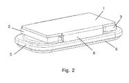
- Fig. 2 shows a bottom perspective view of the miniature transducer according to the present invention. Similar to Fig. 1 , the common yoke 1, the outer magnets 2, 3, the pole piece ring 5 and the cover 6 are depicted. Also, an outer pole piece 8 oppositely arranged relative to the outer pole piece 4 (of Fig. 1 ) is shown. As seen, the pole piece ring 5 is arranged on edges of outer pole pieces 4, 8 (only outer pole piece 8 is depicted in Fig. 2 ) and on outer magnets 2, 3.
- Fig. 3 shows a cross-sectional perspective view across the width of the transducer according to the present invention. Similar to Figs. 1 and 2 , the common yoke 1, the outer pole pieces 4, 8, the outer magnet 3 (outer magnet 2 is not shown in Fig. 2 ), the pole piece ring 5 and the cover 6 (including one sound outlet 7) are shown.
- the outer pole pieces 4, 8 are implemented as bent portions of the common pole piece 1. However, they may also be fabricated separately and attached to the common yoke afterwards.
- the pole piece ring 5 rests on the upper edges of outer pole pieces 4, 8 whereas cover 6 is attached to pole piece ring 5.
- a diaphragm 9 is attached between the pole piece ring 5 and the cover 6.
- a piston 10 is attached to a center portion of the diaphragm 9, the latter comprising a flexible surround 12 surrounding the center portion.
- the diaphragm 9 may have a thickness in the range 5
- the inner magnet 13 is arranged on the common yoke 1.
- the inner magnet 13 is preferably a permanent magnet comprising NdFeB compounds having a remanence flux density of at least 1.2 T, a coercive force of at least 1000 kA/m and an energy product of at least 300 kJ/m 3 .
- an NdFeB N44H may be applied.
- An inner pole piece 14 is arranged on the inner magnet 13, thereby forming air gaps between inner pole piece 14 and outer pole pieces 4, 8. These air gaps are adapted to receive respective voice coil segments 15, 16 which are both attached to piston 10. As depicted in Fig. 3 , voice coil segments 15, 16 are positioned immediately below the flexible surrounds, i.e. outside the center portion of the diaphragm.
- Suitable pole piece materials for the inner pole piece 14 include low carbon content steel materials in accordance with DIN EN 10130.
- voice coil segments 15, 16 are primarily provided by inner magnet 13 in that no outer magnets are provided on the outside of voice coil segments 15, 16.
- an outer magnet for example outer magnet 3, may generate flux that may slightly act on voice coil segments 15, 16.
- the air gaps housing voice coil segments 15, 16 may have a width in the range 0.5 - 0.8 mm, such as around 0.6 mm.
- the average magnetic flux density in the air gap may be in the range 0.3 - 1.5 T, such as in the range 0.5 - 1 T, or any other subset of ranges therein.
- FIG. 4 another cross-sectional view of a miniature transducer according to the present invention is depicted. Compared to the cross-sectional view of Fig. 3 , the cross-sectional view shown in Fig. 4 is rotated 90 degrees in relation thereto. Again, the structural arrangements of the common yoke 1, the inner magnet 13, the outer magnets 2, 3, the inner pole piece 14 and the pole piece ring 5 are depicted.
- voice coil segments 17 and 18 are provided between the inner pole piece 14 and the pole piece ring 5.
- the air gaps are adapted to receive respective voice coil segments 17, 18.
- voice coil segment 17 experiences flux generated by inner magnet 13 and outer magnet 2 in combination.
- voice coil segment 18 experiences flux generated by inner magnet 13 and outer magnet 3 in combination.
- the fluxes acting on voice coil segments 17 and 18 are generated by oppositely arranged inner and outer magnets meaning that voice coil segments 17 and 18 are both exposed to enhanced fluxes.
- the air gaps housing voice coil segments 17, 18 may have a width in the range 0.5 - 0.8 mm, such as around 0.6 mm.
- the average magnetic flux density in the air gap may be in the range 0.3 - 1.5 T, such as in the range 0.5 - 1 T.
- Voice coil segments 17, 18 are both attached to piston 10 via distance elements 19, 20. These distance elements 19, 20 compensate for the fact that the voice coil segments 15, 16 of Fig. 3 are positioned lower than the center portion of the piston. Thus, in order to secure proper attachment to the piston distance elements 19, 20 need to be inserted between voice coil segments 18, 19 and a center portion of the piston 10 to which they are attached.
- the distance elements 19, 20 are preferably integrated in the piston 10.
- FIG. 5 An exploded view of the miniature transducer according to the present invention is shown in Fig. 5 , which shows the common yoke 1 with integrated outer pole pieces 4, 8, the inner magnet 13, the outer magnets 2, 3, the inner pole piece 14 and the pole piece ring 5.
- the shapes of the magnets are shown as being rectangular, but other shapes may also be used in accord with the present concepts.
- the pole piece ring 5 also serves as an exterior surface portion of the housing of the miniature transducer.
- the voice coil 21 comprises previously mentioned voice coil segments 15, 16, 17, 18 interconnected by four corner or bridging portions.
- the impedance of the voice coil 21 may be in the range 4 - 16Q, such as around 8 ⁇ .
- the voice coil is made of a wound copper wire or a wound Copper-clad Aluminium (CCA) wire. In the case of a CCA wire the copper content may be around 15%.
- CCA Copper-clad Aluminium
- the copper content may be around 15%.
- an 8 ⁇ (impedance) voice coil is driven by a voltage of around 2-5 V RMS in order to produce an electrical power of 1-2 W across the transducer.
- the voice coil 21 is attached to piston 10 which is secured to diaphragm 9.
- the diaphragm 9 is kept in position be positioning it between the cover 6 and the pole piece ring 5.
- a number of sound outlets 7, not necessary two (i.e., one or more), are provided in the cover 6.
- An assembled miniature transducer according to the present invention further comprises suitable electric terminals for providing electrical access to the moving voice coil of the transducer.
Landscapes
- Physics & Mathematics (AREA)
- Engineering & Computer Science (AREA)
- Acoustics & Sound (AREA)
- Signal Processing (AREA)
- Audible-Bandwidth Dynamoelectric Transducers Other Than Pickups (AREA)
Applications Claiming Priority (1)
| Application Number | Priority Date | Filing Date | Title |
|---|---|---|---|
| US94523107P | 2007-06-20 | 2007-06-20 |
Publications (2)
| Publication Number | Publication Date |
|---|---|
| EP2007170A1 true EP2007170A1 (de) | 2008-12-24 |
| EP2007170B1 EP2007170B1 (de) | 2020-02-12 |
Family
ID=38949270
Family Applications (1)
| Application Number | Title | Priority Date | Filing Date |
|---|---|---|---|
| EP08158672.9A Active EP2007170B1 (de) | 2007-06-20 | 2008-06-20 | Hocheffizienter elektroakustischer Miniaturwandler mit verringerten Dimensionen |
Country Status (5)
| Country | Link |
|---|---|
| US (2) | US8270661B2 (de) |
| EP (1) | EP2007170B1 (de) |
| JP (1) | JP2009005358A (de) |
| KR (1) | KR20080112166A (de) |
| CN (1) | CN101415136B (de) |
Cited By (1)
| Publication number | Priority date | Publication date | Assignee | Title |
|---|---|---|---|---|
| CN102348154A (zh) * | 2010-07-30 | 2012-02-08 | 歌尔声学股份有限公司 | 微型动圈式换能器 |
Families Citing this family (34)
| Publication number | Priority date | Publication date | Assignee | Title |
|---|---|---|---|---|
| US8270661B2 (en) * | 2007-06-20 | 2012-09-18 | Gettop Europe R&D ApS | High efficient miniature electro-acoustic transducer with reduced dimensions |
| CN202009322U (zh) * | 2011-01-05 | 2011-10-12 | 瑞声声学科技(深圳)有限公司 | 多功能振动器 |
| US8879774B2 (en) * | 2011-04-12 | 2014-11-04 | Harman International Industries, Incorporated | Loudspeaker magnet assembly with two inner magnets comprising a central bore |
| US8744108B2 (en) | 2011-07-12 | 2014-06-03 | Strata Audio LLC | Balanced momentum inertial duct |
| EP2732639A4 (de) | 2011-07-12 | 2015-06-10 | Strata Audio LLC | Versteifer für schwingspulenkörper |
| US10561351B2 (en) | 2011-07-26 | 2020-02-18 | Glysens Incorporated | Tissue implantable sensor with hermetically sealed housing |
| US20140314268A1 (en) * | 2011-12-01 | 2014-10-23 | Ricardo Lazzari | Planar speaker |
| CN102523546A (zh) * | 2011-12-30 | 2012-06-27 | 歌尔声学股份有限公司 | 微型动圈式发声器及其组装方法 |
| CN102595284A (zh) * | 2012-02-20 | 2012-07-18 | 歌尔声学股份有限公司 | 微型电声换能器及其组装方法 |
| CN102595262A (zh) * | 2012-02-22 | 2012-07-18 | 歌尔声学股份有限公司 | 发声器模组及其组装方法 |
| CN102711022A (zh) * | 2012-05-30 | 2012-10-03 | 汉得利(常州)电子有限公司 | 扬声器的磁路装置以及组合磁路扬声器 |
| US10561353B2 (en) | 2016-06-01 | 2020-02-18 | Glysens Incorporated | Biocompatible implantable sensor apparatus and methods |
| US10660550B2 (en) | 2015-12-29 | 2020-05-26 | Glysens Incorporated | Implantable sensor apparatus and methods |
| US9078059B2 (en) * | 2012-08-07 | 2015-07-07 | Jabil Circuit (Beijing), Ltd. | Transducer |
| US20140056446A1 (en) * | 2012-08-27 | 2014-02-27 | AAC Microtech(Changzhou) Co., Ltd. | Micro-Speaker |
| CN202799127U (zh) * | 2012-08-27 | 2013-03-13 | 瑞声光电科技(常州)有限公司 | 微型发声器件 |
| US20140056445A1 (en) * | 2012-08-27 | 2014-02-27 | Aac Microtech (Changzhou) Co., Ltd. | Micro-electroacoustic Device |
| CN202873037U (zh) * | 2012-09-26 | 2013-04-10 | 瑞声光电科技(常州)有限公司 | 复合振膜及应用所述复合振膜的扬声器 |
| CN103152678A (zh) * | 2013-03-08 | 2013-06-12 | 山东共达电声股份有限公司 | 用于电动式扬声器的驱动器 |
| JP2016103664A (ja) * | 2013-03-08 | 2016-06-02 | パナソニック株式会社 | スピーカおよびこのスピーカを用いた電子機器 |
| CN203632854U (zh) * | 2013-09-25 | 2014-06-04 | 瑞声科技(沭阳)有限公司 | 电声器件 |
| US9167350B2 (en) * | 2013-11-15 | 2015-10-20 | Merry Electronics (Suzhou) Co., Ltd. | Magnetic circuit and coaxial speaker using the same |
| CN105228060A (zh) * | 2014-06-05 | 2016-01-06 | 楼氏国际采购中心(马来西亚)私人有限公司 | 磁组件和包含该磁组件的扬声器 |
| FR3026866B1 (fr) * | 2014-10-02 | 2019-09-06 | Dav | Dispositif et procede de commande pour vehicule automobile |
| US9693139B1 (en) * | 2016-03-30 | 2017-06-27 | Ford Global Tecghnologies, LLC | Systems and methods for electronic sound enhancement tuning |
| US10638962B2 (en) | 2016-06-29 | 2020-05-05 | Glysens Incorporated | Bio-adaptable implantable sensor apparatus and methods |
| CN205847585U (zh) * | 2016-07-20 | 2016-12-28 | 瑞声科技(新加坡)有限公司 | 扬声器 |
| CN206341392U (zh) * | 2016-10-25 | 2017-07-18 | 瑞声科技(新加坡)有限公司 | 扬声器 |
| US10638979B2 (en) | 2017-07-10 | 2020-05-05 | Glysens Incorporated | Analyte sensor data evaluation and error reduction apparatus and methods |
| US11278668B2 (en) | 2017-12-22 | 2022-03-22 | Glysens Incorporated | Analyte sensor and medicant delivery data evaluation and error reduction apparatus and methods |
| US11255839B2 (en) | 2018-01-04 | 2022-02-22 | Glysens Incorporated | Apparatus and methods for analyte sensor mismatch correction |
| CN209526877U (zh) * | 2018-12-29 | 2019-10-22 | 瑞声科技(新加坡)有限公司 | 扬声器 |
| US10999681B2 (en) * | 2019-03-15 | 2021-05-04 | Google Llc | Moving magnet actuator with coil for panel audio loudspeakers |
| CN116249055A (zh) * | 2021-12-08 | 2023-06-09 | 佛山鋐利电子有限公司 | 扬声器装置 |
Citations (3)
| Publication number | Priority date | Publication date | Assignee | Title |
|---|---|---|---|---|
| JPH01106700A (ja) * | 1987-10-20 | 1989-04-24 | Victor Co Of Japan Ltd | デジタルスピーカ |
| WO2003063545A1 (en) * | 2002-01-25 | 2003-07-31 | Sonion Horsens A/S | Flexible diaphragm with integrated coil |
| US20060188126A1 (en) * | 2005-01-28 | 2006-08-24 | Andersen Morten K | Miniature multi-loudspeaker module |
Family Cites Families (8)
| Publication number | Priority date | Publication date | Assignee | Title |
|---|---|---|---|---|
| US5461677A (en) * | 1993-09-16 | 1995-10-24 | Ferrofluidics Corporation | Loudspeaker |
| JP2000078689A (ja) * | 1998-09-03 | 2000-03-14 | Sony Corp | 電気・音響変換装置 |
| US6934402B2 (en) * | 2001-01-26 | 2005-08-23 | American Technology Corporation | Planar-magnetic speakers with secondary magnetic structure |
| JP2002335597A (ja) | 2001-05-09 | 2002-11-22 | Citizen Electronics Co Ltd | 複合スピーカー |
| US6940992B2 (en) * | 2002-11-05 | 2005-09-06 | Step Technologies Inc. | Push-push multiple magnetic air gap transducer |
| JP3896970B2 (ja) * | 2003-01-31 | 2007-03-22 | 松下電器産業株式会社 | スピーカ |
| CN1943272B (zh) * | 2005-01-28 | 2012-06-27 | 松下电器产业株式会社 | 电动电声换能器和电子装置 |
| US8270661B2 (en) * | 2007-06-20 | 2012-09-18 | Gettop Europe R&D ApS | High efficient miniature electro-acoustic transducer with reduced dimensions |
-
2008
- 2008-06-19 US US12/142,518 patent/US8270661B2/en active Active
- 2008-06-20 JP JP2008161324A patent/JP2009005358A/ja active Pending
- 2008-06-20 CN CN2008101785761A patent/CN101415136B/zh active Active
- 2008-06-20 KR KR1020080058601A patent/KR20080112166A/ko not_active Withdrawn
- 2008-06-20 EP EP08158672.9A patent/EP2007170B1/de active Active
-
2012
- 2012-08-17 US US13/588,099 patent/US8515118B2/en active Active
Patent Citations (3)
| Publication number | Priority date | Publication date | Assignee | Title |
|---|---|---|---|---|
| JPH01106700A (ja) * | 1987-10-20 | 1989-04-24 | Victor Co Of Japan Ltd | デジタルスピーカ |
| WO2003063545A1 (en) * | 2002-01-25 | 2003-07-31 | Sonion Horsens A/S | Flexible diaphragm with integrated coil |
| US20060188126A1 (en) * | 2005-01-28 | 2006-08-24 | Andersen Morten K | Miniature multi-loudspeaker module |
Cited By (2)
| Publication number | Priority date | Publication date | Assignee | Title |
|---|---|---|---|---|
| CN102348154A (zh) * | 2010-07-30 | 2012-02-08 | 歌尔声学股份有限公司 | 微型动圈式换能器 |
| CN102348154B (zh) * | 2010-07-30 | 2014-12-24 | 歌尔声学股份有限公司 | 微型动圈式换能器 |
Also Published As
| Publication number | Publication date |
|---|---|
| JP2009005358A (ja) | 2009-01-08 |
| EP2007170B1 (de) | 2020-02-12 |
| KR20080112166A (ko) | 2008-12-24 |
| US20120314898A1 (en) | 2012-12-13 |
| US8515118B2 (en) | 2013-08-20 |
| CN101415136A (zh) | 2009-04-22 |
| CN101415136B (zh) | 2013-03-27 |
| US20080317276A1 (en) | 2008-12-25 |
| US8270661B2 (en) | 2012-09-18 |
Similar Documents
| Publication | Publication Date | Title |
|---|---|---|
| EP2007170B1 (de) | Hocheffizienter elektroakustischer Miniaturwandler mit verringerten Dimensionen | |
| US7062063B2 (en) | Electroacoustic transducer | |
| US20050220320A1 (en) | Speaker for mobile terminals and manufacturing method thereof | |
| US20070237352A1 (en) | Miniature loudspeaker and magnetic circuit having integrated air flow passage | |
| CN112929801A (zh) | 扬声器和电子设备 | |
| CN214381371U (zh) | 扬声器和电子设备 | |
| JP6184478B2 (ja) | 広範囲広角ラウドスピーカドライバ | |
| US20120308070A1 (en) | Slim type speaker and magnetic circuit therefor | |
| US8472649B2 (en) | Push-pull type speaker device and method of manufacturing the same | |
| EP2041995A1 (de) | Elektroakustischer miniaturwandler mit integrierter koppelspule | |
| EP2239960A1 (de) | Magnetschaltung und akustische vorrichtung damit | |
| CN101785323A (zh) | 扬声器和使用该扬声器的电子设备 | |
| JP5123247B2 (ja) | 薄型音響電気機械変換器 | |
| EP3637796B1 (de) | Dünner lautsprecher mit einer schwingspule mit dämpferfunktion | |
| US8705789B2 (en) | Magnet-less loudspeaker | |
| US20260052335A1 (en) | High-frequency speaker for earphones | |
| EP4589993A1 (de) | Mehrspaltiger magnetischer motor zur verwendung in lautsprechern | |
| US20250324205A1 (en) | Speaker | |
| KR20250059888A (ko) | 슬림 스피커 | |
| JPH0759195A (ja) | スピーカ | |
| JP2004356832A (ja) | スピーカ |
Legal Events
| Date | Code | Title | Description |
|---|---|---|---|
| PUAI | Public reference made under article 153(3) epc to a published international application that has entered the european phase |
Free format text: ORIGINAL CODE: 0009012 |
|
| AK | Designated contracting states |
Kind code of ref document: A1 Designated state(s): AT BE BG CH CY CZ DE DK EE ES FI FR GB GR HR HU IE IS IT LI LT LU LV MC MT NL NO PL PT RO SE SI SK TR |
|
| AX | Request for extension of the european patent |
Extension state: AL BA MK RS |
|
| 17P | Request for examination filed |
Effective date: 20090624 |
|
| 17Q | First examination report despatched |
Effective date: 20090730 |
|
| AKX | Designation fees paid |
Designated state(s): AT BE BG CH CY CZ DE DK EE ES FI FR GB GR HR HU IE IS IT LI LT LU LV MC MT NL NO PL PT RO SE SI SK TR |
|
| RAP1 | Party data changed (applicant data changed or rights of an application transferred) |
Owner name: PULSE HVT APS |
|
| RAP1 | Party data changed (applicant data changed or rights of an application transferred) |
Owner name: GETTOP EUROPE R&D APS |
|
| RAP1 | Party data changed (applicant data changed or rights of an application transferred) |
Owner name: SHANDONG GETTOP ACOUSTIC CO., LTD |
|
| STAA | Information on the status of an ep patent application or granted ep patent |
Free format text: STATUS: EXAMINATION IS IN PROGRESS |
|
| GRAP | Despatch of communication of intention to grant a patent |
Free format text: ORIGINAL CODE: EPIDOSNIGR1 |
|
| STAA | Information on the status of an ep patent application or granted ep patent |
Free format text: STATUS: GRANT OF PATENT IS INTENDED |
|
| INTG | Intention to grant announced |
Effective date: 20190729 |
|
| GRAS | Grant fee paid |
Free format text: ORIGINAL CODE: EPIDOSNIGR3 |
|
| GRAJ | Information related to disapproval of communication of intention to grant by the applicant or resumption of examination proceedings by the epo deleted |
Free format text: ORIGINAL CODE: EPIDOSDIGR1 |
|
| GRAL | Information related to payment of fee for publishing/printing deleted |
Free format text: ORIGINAL CODE: EPIDOSDIGR3 |
|
| STAA | Information on the status of an ep patent application or granted ep patent |
Free format text: STATUS: EXAMINATION IS IN PROGRESS |
|
| GRAR | Information related to intention to grant a patent recorded |
Free format text: ORIGINAL CODE: EPIDOSNIGR71 |
|
| STAA | Information on the status of an ep patent application or granted ep patent |
Free format text: STATUS: GRANT OF PATENT IS INTENDED |
|
| INTC | Intention to grant announced (deleted) | ||
| GRAA | (expected) grant |
Free format text: ORIGINAL CODE: 0009210 |
|
| STAA | Information on the status of an ep patent application or granted ep patent |
Free format text: STATUS: THE PATENT HAS BEEN GRANTED |
|
| INTG | Intention to grant announced |
Effective date: 20191217 |
|
| AK | Designated contracting states |
Kind code of ref document: B1 Designated state(s): AT BE BG CH CY CZ DE DK EE ES FI FR GB GR HR HU IE IS IT LI LT LU LV MC MT NL NO PL PT RO SE SI SK TR |
|
| REG | Reference to a national code |
Ref country code: GB Ref legal event code: FG4D |
|
| REG | Reference to a national code |
Ref country code: CH Ref legal event code: EP |
|
| REG | Reference to a national code |
Ref country code: AT Ref legal event code: REF Ref document number: 1233713 Country of ref document: AT Kind code of ref document: T Effective date: 20200215 |
|
| REG | Reference to a national code |
Ref country code: DE Ref legal event code: R096 Ref document number: 602008062102 Country of ref document: DE |
|
| REG | Reference to a national code |
Ref country code: IE Ref legal event code: FG4D |
|
| PG25 | Lapsed in a contracting state [announced via postgrant information from national office to epo] |
Ref country code: NO Free format text: LAPSE BECAUSE OF FAILURE TO SUBMIT A TRANSLATION OF THE DESCRIPTION OR TO PAY THE FEE WITHIN THE PRESCRIBED TIME-LIMIT Effective date: 20200512 Ref country code: FI Free format text: LAPSE BECAUSE OF FAILURE TO SUBMIT A TRANSLATION OF THE DESCRIPTION OR TO PAY THE FEE WITHIN THE PRESCRIBED TIME-LIMIT Effective date: 20200212 |
|
| REG | Reference to a national code |
Ref country code: LT Ref legal event code: MG4D |
|
| REG | Reference to a national code |
Ref country code: NL Ref legal event code: MP Effective date: 20200212 |
|
| PG25 | Lapsed in a contracting state [announced via postgrant information from national office to epo] |
Ref country code: GR Free format text: LAPSE BECAUSE OF FAILURE TO SUBMIT A TRANSLATION OF THE DESCRIPTION OR TO PAY THE FEE WITHIN THE PRESCRIBED TIME-LIMIT Effective date: 20200513 Ref country code: BG Free format text: LAPSE BECAUSE OF FAILURE TO SUBMIT A TRANSLATION OF THE DESCRIPTION OR TO PAY THE FEE WITHIN THE PRESCRIBED TIME-LIMIT Effective date: 20200512 Ref country code: LV Free format text: LAPSE BECAUSE OF FAILURE TO SUBMIT A TRANSLATION OF THE DESCRIPTION OR TO PAY THE FEE WITHIN THE PRESCRIBED TIME-LIMIT Effective date: 20200212 Ref country code: IS Free format text: LAPSE BECAUSE OF FAILURE TO SUBMIT A TRANSLATION OF THE DESCRIPTION OR TO PAY THE FEE WITHIN THE PRESCRIBED TIME-LIMIT Effective date: 20200612 Ref country code: SE Free format text: LAPSE BECAUSE OF FAILURE TO SUBMIT A TRANSLATION OF THE DESCRIPTION OR TO PAY THE FEE WITHIN THE PRESCRIBED TIME-LIMIT Effective date: 20200212 Ref country code: HR Free format text: LAPSE BECAUSE OF FAILURE TO SUBMIT A TRANSLATION OF THE DESCRIPTION OR TO PAY THE FEE WITHIN THE PRESCRIBED TIME-LIMIT Effective date: 20200212 |
|
| PG25 | Lapsed in a contracting state [announced via postgrant information from national office to epo] |
Ref country code: NL Free format text: LAPSE BECAUSE OF FAILURE TO SUBMIT A TRANSLATION OF THE DESCRIPTION OR TO PAY THE FEE WITHIN THE PRESCRIBED TIME-LIMIT Effective date: 20200212 |
|
| PG25 | Lapsed in a contracting state [announced via postgrant information from national office to epo] |
Ref country code: EE Free format text: LAPSE BECAUSE OF FAILURE TO SUBMIT A TRANSLATION OF THE DESCRIPTION OR TO PAY THE FEE WITHIN THE PRESCRIBED TIME-LIMIT Effective date: 20200212 Ref country code: DK Free format text: LAPSE BECAUSE OF FAILURE TO SUBMIT A TRANSLATION OF THE DESCRIPTION OR TO PAY THE FEE WITHIN THE PRESCRIBED TIME-LIMIT Effective date: 20200212 Ref country code: SK Free format text: LAPSE BECAUSE OF FAILURE TO SUBMIT A TRANSLATION OF THE DESCRIPTION OR TO PAY THE FEE WITHIN THE PRESCRIBED TIME-LIMIT Effective date: 20200212 Ref country code: PT Free format text: LAPSE BECAUSE OF FAILURE TO SUBMIT A TRANSLATION OF THE DESCRIPTION OR TO PAY THE FEE WITHIN THE PRESCRIBED TIME-LIMIT Effective date: 20200705 Ref country code: CZ Free format text: LAPSE BECAUSE OF FAILURE TO SUBMIT A TRANSLATION OF THE DESCRIPTION OR TO PAY THE FEE WITHIN THE PRESCRIBED TIME-LIMIT Effective date: 20200212 Ref country code: RO Free format text: LAPSE BECAUSE OF FAILURE TO SUBMIT A TRANSLATION OF THE DESCRIPTION OR TO PAY THE FEE WITHIN THE PRESCRIBED TIME-LIMIT Effective date: 20200212 Ref country code: ES Free format text: LAPSE BECAUSE OF FAILURE TO SUBMIT A TRANSLATION OF THE DESCRIPTION OR TO PAY THE FEE WITHIN THE PRESCRIBED TIME-LIMIT Effective date: 20200212 Ref country code: LT Free format text: LAPSE BECAUSE OF FAILURE TO SUBMIT A TRANSLATION OF THE DESCRIPTION OR TO PAY THE FEE WITHIN THE PRESCRIBED TIME-LIMIT Effective date: 20200212 |
|
| REG | Reference to a national code |
Ref country code: DE Ref legal event code: R097 Ref document number: 602008062102 Country of ref document: DE |
|
| REG | Reference to a national code |
Ref country code: AT Ref legal event code: MK05 Ref document number: 1233713 Country of ref document: AT Kind code of ref document: T Effective date: 20200212 |
|
| PLBE | No opposition filed within time limit |
Free format text: ORIGINAL CODE: 0009261 |
|
| STAA | Information on the status of an ep patent application or granted ep patent |
Free format text: STATUS: NO OPPOSITION FILED WITHIN TIME LIMIT |
|
| 26N | No opposition filed |
Effective date: 20201113 |
|
| PG25 | Lapsed in a contracting state [announced via postgrant information from national office to epo] |
Ref country code: MC Free format text: LAPSE BECAUSE OF FAILURE TO SUBMIT A TRANSLATION OF THE DESCRIPTION OR TO PAY THE FEE WITHIN THE PRESCRIBED TIME-LIMIT Effective date: 20200212 Ref country code: IT Free format text: LAPSE BECAUSE OF FAILURE TO SUBMIT A TRANSLATION OF THE DESCRIPTION OR TO PAY THE FEE WITHIN THE PRESCRIBED TIME-LIMIT Effective date: 20200212 Ref country code: AT Free format text: LAPSE BECAUSE OF FAILURE TO SUBMIT A TRANSLATION OF THE DESCRIPTION OR TO PAY THE FEE WITHIN THE PRESCRIBED TIME-LIMIT Effective date: 20200212 |
|
| REG | Reference to a national code |
Ref country code: CH Ref legal event code: PL |
|
| PG25 | Lapsed in a contracting state [announced via postgrant information from national office to epo] |
Ref country code: SI Free format text: LAPSE BECAUSE OF FAILURE TO SUBMIT A TRANSLATION OF THE DESCRIPTION OR TO PAY THE FEE WITHIN THE PRESCRIBED TIME-LIMIT Effective date: 20200212 Ref country code: PL Free format text: LAPSE BECAUSE OF FAILURE TO SUBMIT A TRANSLATION OF THE DESCRIPTION OR TO PAY THE FEE WITHIN THE PRESCRIBED TIME-LIMIT Effective date: 20200212 |
|
| PG25 | Lapsed in a contracting state [announced via postgrant information from national office to epo] |
Ref country code: LU Free format text: LAPSE BECAUSE OF NON-PAYMENT OF DUE FEES Effective date: 20200620 |
|
| REG | Reference to a national code |
Ref country code: BE Ref legal event code: MM Effective date: 20200630 |
|
| PG25 | Lapsed in a contracting state [announced via postgrant information from national office to epo] |
Ref country code: IE Free format text: LAPSE BECAUSE OF NON-PAYMENT OF DUE FEES Effective date: 20200620 Ref country code: LI Free format text: LAPSE BECAUSE OF NON-PAYMENT OF DUE FEES Effective date: 20200630 Ref country code: CH Free format text: LAPSE BECAUSE OF NON-PAYMENT OF DUE FEES Effective date: 20200630 |
|
| PG25 | Lapsed in a contracting state [announced via postgrant information from national office to epo] |
Ref country code: BE Free format text: LAPSE BECAUSE OF NON-PAYMENT OF DUE FEES Effective date: 20200630 |
|
| PG25 | Lapsed in a contracting state [announced via postgrant information from national office to epo] |
Ref country code: TR Free format text: LAPSE BECAUSE OF FAILURE TO SUBMIT A TRANSLATION OF THE DESCRIPTION OR TO PAY THE FEE WITHIN THE PRESCRIBED TIME-LIMIT Effective date: 20200212 Ref country code: MT Free format text: LAPSE BECAUSE OF FAILURE TO SUBMIT A TRANSLATION OF THE DESCRIPTION OR TO PAY THE FEE WITHIN THE PRESCRIBED TIME-LIMIT Effective date: 20200212 Ref country code: CY Free format text: LAPSE BECAUSE OF FAILURE TO SUBMIT A TRANSLATION OF THE DESCRIPTION OR TO PAY THE FEE WITHIN THE PRESCRIBED TIME-LIMIT Effective date: 20200212 |
|
| REG | Reference to a national code |
Ref country code: FR Ref legal event code: PLFP Year of fee payment: 16 |
|
| PGFP | Annual fee paid to national office [announced via postgrant information from national office to epo] |
Ref country code: FR Payment date: 20250306 Year of fee payment: 18 |
|
| PGFP | Annual fee paid to national office [announced via postgrant information from national office to epo] |
Ref country code: DE Payment date: 20250320 Year of fee payment: 18 |
|
| PGFP | Annual fee paid to national office [announced via postgrant information from national office to epo] |
Ref country code: GB Payment date: 20250403 Year of fee payment: 18 |