EP2007126A1 - Scan-Flow-Ausrichtung - Google Patents
Scan-Flow-Ausrichtung Download PDFInfo
- Publication number
- EP2007126A1 EP2007126A1 EP08251761A EP08251761A EP2007126A1 EP 2007126 A1 EP2007126 A1 EP 2007126A1 EP 08251761 A EP08251761 A EP 08251761A EP 08251761 A EP08251761 A EP 08251761A EP 2007126 A1 EP2007126 A1 EP 2007126A1
- Authority
- EP
- European Patent Office
- Prior art keywords
- scan
- image
- carriage
- starting location
- coordinate system
- Prior art date
- Legal status (The legal status is an assumption and is not a legal conclusion. Google has not performed a legal analysis and makes no representation as to the accuracy of the status listed.)
- Ceased
Links
- 238000000034 method Methods 0.000 claims abstract description 41
- 230000003287 optical effect Effects 0.000 claims description 4
- 238000001228 spectrum Methods 0.000 claims description 3
- 230000002093 peripheral effect Effects 0.000 description 5
- 239000000463 material Substances 0.000 description 4
- 230000008569 process Effects 0.000 description 4
- 230000006870 function Effects 0.000 description 3
- 238000005286 illumination Methods 0.000 description 3
- 238000010586 diagram Methods 0.000 description 2
- 238000009499 grossing Methods 0.000 description 2
- 230000009466 transformation Effects 0.000 description 2
- 230000006978 adaptation Effects 0.000 description 1
- 230000003321 amplification Effects 0.000 description 1
- 238000003491 array Methods 0.000 description 1
- 230000008901 benefit Effects 0.000 description 1
- 238000001444 catalytic combustion detection Methods 0.000 description 1
- 238000006243 chemical reaction Methods 0.000 description 1
- 239000003086 colorant Substances 0.000 description 1
- 230000000295 complement effect Effects 0.000 description 1
- 230000001419 dependent effect Effects 0.000 description 1
- 230000000694 effects Effects 0.000 description 1
- 238000004519 manufacturing process Methods 0.000 description 1
- 230000005055 memory storage Effects 0.000 description 1
- 238000003199 nucleic acid amplification method Methods 0.000 description 1
- 230000009467 reduction Effects 0.000 description 1
- 230000004044 response Effects 0.000 description 1
- 230000000284 resting effect Effects 0.000 description 1
- 230000003595 spectral effect Effects 0.000 description 1
Images


Classifications
-
- H—ELECTRICITY
- H04—ELECTRIC COMMUNICATION TECHNIQUE
- H04N—PICTORIAL COMMUNICATION, e.g. TELEVISION
- H04N1/00—Scanning, transmission or reproduction of documents or the like, e.g. facsimile transmission; Details thereof
- H04N1/024—Details of scanning heads ; Means for illuminating the original
- H04N1/028—Details of scanning heads ; Means for illuminating the original for picture information pick-up
- H04N1/02815—Means for illuminating the original, not specific to a particular type of pick-up head
-
- H—ELECTRICITY
- H04—ELECTRIC COMMUNICATION TECHNIQUE
- H04N—PICTORIAL COMMUNICATION, e.g. TELEVISION
- H04N1/00—Scanning, transmission or reproduction of documents or the like, e.g. facsimile transmission; Details thereof
- H04N1/04—Scanning arrangements, i.e. arrangements for the displacement of active reading or reproducing elements relative to the original or reproducing medium, or vice versa
- H04N1/047—Detection, control or error compensation of scanning velocity or position
- H04N1/0473—Detection, control or error compensation of scanning velocity or position in subscanning direction, e.g. picture start or line-to-line synchronisation
-
- H—ELECTRICITY
- H04—ELECTRIC COMMUNICATION TECHNIQUE
- H04N—PICTORIAL COMMUNICATION, e.g. TELEVISION
- H04N2201/00—Indexing scheme relating to scanning, transmission or reproduction of documents or the like, and to details thereof
- H04N2201/04—Scanning arrangements
- H04N2201/0402—Arrangements not specific to a particular one of the scanning methods covered by groups H04N1/04 - H04N1/207
- H04N2201/0448—Arrangements not specific to a particular one of the scanning methods covered by groups H04N1/04 - H04N1/207 for positioning scanning elements not otherwise provided for; Aligning, e.g. using an alignment calibration pattern
-
- H—ELECTRICITY
- H04—ELECTRIC COMMUNICATION TECHNIQUE
- H04N—PICTORIAL COMMUNICATION, e.g. TELEVISION
- H04N2201/00—Indexing scheme relating to scanning, transmission or reproduction of documents or the like, and to details thereof
- H04N2201/04—Scanning arrangements
- H04N2201/047—Detection, control or error compensation of scanning velocity or position
- H04N2201/04701—Detection of scanning velocity or position
- H04N2201/04703—Detection of scanning velocity or position using the scanning elements as detectors, e.g. by performing a prescan
-
- H—ELECTRICITY
- H04—ELECTRIC COMMUNICATION TECHNIQUE
- H04N—PICTORIAL COMMUNICATION, e.g. TELEVISION
- H04N2201/00—Indexing scheme relating to scanning, transmission or reproduction of documents or the like, and to details thereof
- H04N2201/04—Scanning arrangements
- H04N2201/047—Detection, control or error compensation of scanning velocity or position
- H04N2201/04701—Detection of scanning velocity or position
- H04N2201/04715—Detection of scanning velocity or position by detecting marks or the like, e.g. slits
- H04N2201/0472—Detection of scanning velocity or position by detecting marks or the like, e.g. slits on or adjacent the sheet support
-
- H—ELECTRICITY
- H04—ELECTRIC COMMUNICATION TECHNIQUE
- H04N—PICTORIAL COMMUNICATION, e.g. TELEVISION
- H04N2201/00—Indexing scheme relating to scanning, transmission or reproduction of documents or the like, and to details thereof
- H04N2201/04—Scanning arrangements
- H04N2201/047—Detection, control or error compensation of scanning velocity or position
- H04N2201/04701—Detection of scanning velocity or position
- H04N2201/04731—Detection of scanning velocity or position in the sub-scan direction
Definitions
- Scanners are used in a wide variety of settings, including the home and office, to capture electronic images of documents and objects.
- Conventional scanners operate by moving the scan carriage into and out of a home position.
- the home position of a scanner is a resting position where a scan carriage returns to between scans.
- a scan carriage is moved from the home position to perform a dark and white calibration, and may move back to the home position if the remaining distance is not enough to ramp up the scan carriage speed before commencing a scan.
- the scan carriage moves to the scan target on the scan bed to start the scan and to capture the image.
- the scan carriage returns home after performing the scan and remains there waiting for the next scan.
- Scanners using this conventional approach use the data from the scan to create the electronic file of the image.
- Scanners are capable of achieving better color accuracy by scanning for each scan target twice, each time with a lamp of different optical spectrum. After capturing two images, the images are combined using computer executable instructions storable in a memory and executable by a processor to execute a method that produces better color accuracy than single scan techniques. In order to achieve the best color accuracy when combining two images, the two scan images must have a particular alignment. This requirement is challenging given the fact that cost effective mechanical hardware components are used in scanners to keep the price of the scanners low.
- a particular alignment of the scan carriage that allows for the images from the scan to be combined into a new image with better color accuracy with conventional scan flow design may not be known due to variance in product manufacturing tolerances since the scanner does not know the precise location of the scan carriage, and the home position itself is imprecise as well. For example, on a given scanner the precise orientation/location of the home position may vary by several millimeters. Furthermore, there will be an additional error introduced when the scan carriage goes back to the home position after calibration before heading out to the scan bed, due to mechanical vibration associated with the scan carriage returning to the home position.
- Embodiments of the disclosure herein provide systems and methods for a scan flow of the scan hardware in a scanning device.
- a method for scan flow alignment is disclosed, this method is used to increase the accuracy of the location of the scan carriage in relation to the scan target to approximately 0.01 mm at 600 ppi for a two scan sequence.
- An embodiment of a method aligning a scan carriage includes selecting a starting location for a scan and determining the location of a reference mark.
- the location of the reference mark is found using computer-executable instructions stored a computer readable medium to perform a method for execution by a processor to perform a method that uses a smoothing filter and edge information from the mark with a particular accuracy. This reference mark is used as the coordinate system origin.
- the scan carriage moves from the coordinate system origin to the scan starting location and a scan of the object is performed from the starting location to capture an image.
- a second scan can be performed using the same method for aligning the scan carriage, but with a lamp of different optical spectrum than the lamp used in the first scan.
- the scan carriage returns to the home position after performing the first scan, but before performing the second scan.
- the images from two scans can be combined to create a single image.
- the two scan images In order to achieve the best color accuracy when combining images to create a single image, the two scan images have a particular alignment. This alignment is difficult to achieve, but the present disclosure includes a scan flow that allows for the proper alignment of the scan carriage despite the fact the scanner does not know the absolute precise position of the scan carriage and the home position for the scan carriage itself is imprecise as well.
- the scan flow in the present disclosure provides a method to locate a start location for the scan carriage, thus allowing for the scan carriage to move a substantially fixed distance between a reference mark and the starting location of the scan for each scan of a given object.
- this scan flow removes error caused by imprecision in the scan hardware by having the scan process start approximately from the same origin position and move a substantially constant, fixed distance to the scan starting location.
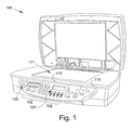
- Figure 1 illustrates an example scanning apparatus suitable to implement embodiments of the present disclosure.
- the embodiment of Figure 1 illustrates an image scanning apparatus 100 that can, in various embodiments, be connected to a number of remote devices to form an image scanning system.
- Remote devices can include, for example, computing devices such as one or more desktop computers, laptop computers, and/or workstations, among other types of devices.
- the image scanning apparatus 100 can be included as part of, or connected to form, a multi-functional system including more than one function mode, such as scanning, copying, faxing, and/or printing.
- a system can include, in various locations within scanning apparatus 100, one or more processors and/or application modules suitable for executing software programming (e.g., executable instructions) and can include, in various locations, one or more memory devices.
- the image scanning system that includes the image scanning apparatus 100 can include one or more of the embodiments described herein.
- the embodiment of Figure 1 illustrates an image scanning apparatus 100 that includes one or more control keys 103 that can control on/off status, sleep status, and/or function mode, among other activities.
- the image scanning apparatus 100 can include one or more display screens with a number of associated user input interfaces 105 that can be used, for example, in assigning a label to an image being scanned.
- the image scanning apparatus 100 also can include one or more scan mode display screens 107.
- the display screens can display information using LCD graphics, among other display types.
- Scan mode selectors 109 can be used for control of the scan operation functionalities described below.
- the embodiment of the image scanning apparatus 100 illustrated in Figure 1 includes a scan bed 111 that can, in various embodiments, be formed from any suitable wavelength transparent, semi-transparent, or translucent material that allows throughput of illuminating and/or reflected light.
- the scan bed 111 can have various geometric formats of various sizes (e.g., squares, rectangles, circles, ovals, trapezoids, etc.) to accommodate particular objects to be associated therewith and scanned therethrough.
- the scan bed 111 is usually referred to in the singular in the present disclosure, some embodiments can have more than one scan window to enable use of various configurations of arrays of multiple scan carriages.
- the multiple scan carriages described in the present disclosure can be located within the housing of the image scanning device 100 and one or more of the multiple scan carriages can be associated with a light source for illumination of an object (not shown) laid on or placed above the scan bed 111. Light can be reflected by the object through the scan bed 111 and detected by a number of photosensitive elements associated with each of the multiple scan carriages.
- the scan bed 111 can have a number of indicators 113 associated therewith.
- the indicators 113 can be arranged in various positions and patterns and can be used for a variety of purposes.
- an image scanning apparatus 100 as described in the present disclosure can have a section of the housing 115 on one or more edge of the scan bed 111 with a volume capable of containing the multiple scan carriages.
- the one or more sections of housing 115 can allow an array of scan modules to begin and end passage across a scan bed 111 outside a perimeter of one or more scan windows.
- FIG 2 illustrates an embodiment of prior art scan hardware includable in an apparatus, such as the scanning apparatus of Figure 1 , used to perform a scan of an object.
- the scan hardware 200 of Figure 2 includes a scan carriage 202, a home position 204 for the scan carriage 202, and a scan bed 206.
- the home position 204 is where the scan carriage 202 is located when the scan carriage is not being used. Also, the scan carriage 202 returns to the home position 204 after each scan.
- the scan carriage 202 is used to capture an image of an object 208 placed on the scan bed 206.
- the scan carriage 202 captures the image an object 208 placed on the scan bed 206 by the use of various configurations of components that can include any number of mirrors, lenses, filters, light sources, and/or photosensitive elements, for example, charge coupled devices (CCD), contact image sensors (CIS), etc., among other components.
- CCD charge coupled devices
- CIS contact image sensors
- an object 208 is placed on the scan bed 206.
- the scan starting location is selected based on the placement of the object 208 on the scan bed 206.
- the scan starting location is where the scan carriage 202 begins the process of capturing an image of the object 208.
- the scan starting location can be selected manually, through the use of a mouse, a display, and a low resolution scan of the object 208, or automatically by a processor that has executable instructions to select the scan starting location.
- the scan carriage 202 starts from the home position 204, conducts a dark and white calibration, moves to the scan starting location, and then passes under the object 208 to record an image of the object.
- the scan carriage 202 then returns to the home position, ready for the next scan.
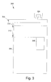
- Figure 3 illustrates an embodiment of scan hardware includable in an apparatus, such as the scanning apparatus of Figure 1 , used to perform a scan of an object.
- the scan hardware 300 illustrated in Figure 3 represents the hardware configuration for a scanner that includes the embodiments of the present disclosure.
- the scan hardware 300 of Figure 3 includes a scan carriage 302, a home position 304 for the scan carriage 302, a scan bed 306, and a reference mark 310.
- the home position 304 is where the scan carriage 302 is located when the scan carriage is not being used.
- the scan carriage 302 is used to capture an image of an object 308 placed on the scan bed 306.
- the scan carriage 302 captures the image an object 308 placed on the scan bed 306 by the use of various configurations of components that can include any number of mirrors, lenses, filters, light sources, and/or photosensitive elements, for example, charge coupled devices (CCD), contact image sensors (CIS), etc., among other components.
- CCD charge coupled devices
- CIS contact image sensors
- an object 308 is placed on the scan bed 306.
- the scan starting location is selected based on the placement of the object 308 on the scan bed 306.
- the scan carriage 302 starts from the home position 304.
- the scan carriage 302 moves from the home position 304 and locates the reference mark 310.
- the reference mark 310 is located by using a computer readable medium having computer-executable instructions stored thereon for execution by a processor to perform a method that uses a smoothing filter and edge information from the mark with a particular accuracy.
- the center of the reference mark 310 is found by a method using the weighted sum of the edge image of the reference mark 310.
- the location of the reference mark 310 is used as the coordinate system origin to ensure the scan carriage 302 scans similar portions of object 308 in consecutive scans of object 308.
- a dark and white calibration is performed either before or after the reference mark 310 location is determined.
- the scan carriage 302 moves directly to the scan starting location.
- the scan carriage 302 then passes under the object 308 to record an image of the object.
- the scan carriage 302 moves back to the home position and starts a second scan of object 308 using the same process.
- the scan carriage moves a distance 312 to the starting location of the scan for every scan.
- the reference mark 310 provides an origin for the scan carriage to start the scan operation in both the vertical and horizontal coordinates of the scan plane.
- the scan carriage's positional accuracy has the largest variability in the direction of the scan carriage's movement over the object 308, so providing an origin for the scan carriage 302 in that direction allows the desired positional accuracy to be achieved. This ensures that scan carriage 302 is starting its scan from substantially the same location each time, and therefore, is able to capture approximately the same image in each scan of object 308.
- the image from the first scan and the image from the second scan are combined to form a single, new image that has better color accuracy than the either of the first or second scans individually.
- Figure 4 illustrates a portion of a scanner in which two light sources 402, 404 are depicted that are used to perform a scan of an object.
- Scanner 400 performs two scans, each capturing an image of the object.
- One of the two light sources 402, 404 is used while performing a first scan of an object and the light source not used in the first scan, light source 402 or 404, is used while performing a second scan of the object.
- the two images can then be combined using the method disclosed in Great Britain patent application number GB0608362.0 titled 'Image Processing System And Method' and filed October 10, 2005.
- Light sources 402, 404 are connected to a common drive train (not shown), along with the folded optics 406 and three rows of RGB charge-coupled device (CCD) elements 408. Both light sources can be translated across a material to be scanned (410) together. Light sources 402, 404 are displaced from one another by a small distance and can extend across the width of a scanner or a portion thereof. For example, light sources can extend across the scanner panel in order to ensure that all material placed on the scanner panel can be sufficiently illuminated. Material to be scanned is separately scanned at least twice by scanning light sources 402, 404 across the object. One, other or both light sources are selected (illuminated) during a scan. The scans can occur at different times and/or speeds.
- CCD color-coupled device
- a portion of an object to be scanned is firstly illuminated with one light source (402) and then the other (404).
- Image data representing an image of the portion is then generated using light reflected from or transmitted through the portion (depending on the desired nature of the scanner).
- the data is generated using the CCDs 408 (or similar image elements such as CMOS elements for example, or an area image sensor) which are operable to generated image data using light incident upon them.
- Light can be passed through a lens 412, for example, before it reaches the CCD elements.
- the image data comprises at least six color channels of information (e.g. RGB image data resulting from illumination with light source 402 and R'G'B' image data resulting from illumination with light source 404).
- the six channels comprise additional color information which can be used to improve the accuracy of resultant scan data.
- the light sources 402, 404 are each configured to have different spectral response frequency characteristics to produce enhanced color information in the scanned image of the object. It should be understood that embodiments of the present invention may be used in both reflective and transmissive scanning applications.
- the six color channels of data generated by the two light sources 401, 402 are decomposed into respective higher and lower spatial frequency components.
- a low pass filter can be applied to the data for the channel (such as a Gaussian spatial filter for example). This results in data in which the higher spatial frequency image components have been filtered out. This can be repeated for each channel, and the result subtracted from the original data to recover the complementary high frequency component for a channel. The combination of the lower and higher frequency channel components will result in the original image for each channel.
- a 3x6 color transform is applied to the lower frequency components.
- This transform does not significantly amplify noise with respect to the original component if the noise reduction resulting from the low pass filter is sufficient. This is because, in general, visible noise is carried in the higher spatial frequency components of an image, and therefore the application of the transform to a lower frequency component, i.e. a component in which these noise elements have been greatly reduced, will not substantially amplify noise with respect to the original, if at all.
- a 3x6 color transform can be applied to the higher frequency components. This transform can be chosen to suppress noise since the image details will have high correlation for the different illuminants, while the image noise will be uncorrelated for the different illuminants.
- a 3x3 color transform is applied only to the 3 high frequency channels corresponding to a single scan. This scan is chosen as the one that gives the best overall color accuracy and/or noise performance. This is in turn dependent on which of the individual light sources gives the best color accuracy and/or noise performance.
- one scan can be performed with lower fidelity, for example with lower resolution or with worse noise performance, as only the low spatial frequencies are needed for the 3x6 color transform - in this case it is clear that the other scan provides the high frequency information.
- Another possibility is that one scan has both light sources on and the other is the absence of one or other light sources - it is clear then that the high frequency should come from the 'both light source on' condition and that the choice is now which light source to turn off for the second scan.
- the 3x6 and 3x3 transforms are chosen to map the data from the channels to the same target color space.
- the 3x6 transform gives better color accuracy because it has more color information (6 channels not 3), however it may also amplify noise in order to get the improved color accuracy.
- a 3x6 transformation need only be applied to the low frequency components, which have lower noise (as explained above).
- the higher frequencies (derived from only 3 channels of a single scan) have a 3x3 transformation applied to them. Since color errors in the high frequencies cannot generally be seen, this does not matter in practice.
- the 3x3 transform is chosen so as not to amplify noise greatly.
- the lower accuracy of colors in the higher frequency components will not affect overall quality since the high frequencies only influence a small spatial extent and are largely achromatic.
- the resulting (transformed) 3 low frequency channels and 3 high frequency channels are combined to form the resultant target image.
- the resultant image will be substantially free from noise amplification and because the high frequency component comes from a single scan, it will also be substantially (or completely in some cases) free from other artifacts such as ghosting and blurring.
- one scan only contributes low frequency components it is possible to perform that scan with lower fidelity, for example with lower resolution, than the other provided that a substantially equivalent low frequency component can be generated from each scan. Additionally, a lower resolution scan can be performed first and then the conversion from 6 to 3 channels performed on the fly as the second higher resolution scan is performed (with consequent advantage in terms of memory storage requirements for example).
- Figure 5 is a block diagram illustrating using a reference mark as the origin of a coordinate system to allow for positional accuracy in successive scans of the same object according to an embodiment of the present disclosure.
- Figure 5 illustrates a method that allows for alignment of a scan carriage during a scan operation.
- the method includes computer executable instructions storable in a memory and executable by a processor that can be used to conduct a scan with the precision required for scanners that implement a combining feature to create images that have better color accuracy.
- the method 500 conducts a scan by selecting the starting location for a scan 510 and determining the location of the reference mark 520.
- the reference mark is used as the coordinate system origin 530.
- the reference mark provides an origin for the scan carriage to start the scan operation in both the vertical and horizontal coordinates of the scan plane.
- the scan carriage is moved from the coordinate system origin to the scan starting location 540 and a scan is performed from the starting location to capture an image of an object 550.
- Method 500 allows for the images from two scans with a particular positional accuracy to be combined to form an image of approximately 0.01 mm at 600 ppi scan resolution with great color accuracy because when the scan carriage is at the coordinate system origin 530 it moves a fixed distance to the scan starting location 550. This distance is nearly constant for every scan of a given object that occurs, if the object is placed on the scan bed and does not move from the initial position in which it was placed on the scan bed. Because the scan carriage moves a substantially fixed distance from an origin to a starting location, approximately an identical image is captured during each scan of an object allowing these images to be combined to form an image with improved color accuracy.
- Figure 6 illustrates a system suitable to implement embodiments of the present disclosure.
- Figure 6 illustrates that a scanning device, including embodiments described herein, can be incorporated as part of a system 600.
- the system includes a scanning device 602, such as a scanner as shown in Figure 1 .
- the system 600 is operable to receive data and interpret the data from the scan of an image in a particular image position.
- the system 600 can include software and/or application modules thereon for receiving and interpreting data in order to achieve the desired image quality functions.
- the software and/or application modules can be located on any device that is directly or indirectly connected to the scanning device 602 within the system 600.
- the scanning device 602 can include a controller 604 and a memory 606.
- the controller 604 and the one or more memory devices 606 are operable to implement the method embodiments described herein.
- the one or more memory devices 606 include memory devices 606 on which data, including computer readable instructions, and other information of the like can reside.
- scanning device 602 can be networked to one or more remote devices 610 over a number of data links, shown as 622.
- the number of data links 622 can include one or more physical and one or more wireless connections, and any combination thereof, as part of a network. That is, the scanning device 602 and the one or more remote devices 610 can be directly connected and can be connected as part of a wider network having a plurality of data links 622.
- a remote device 612 can include a device having a display such as a desktop computer, laptop computer, a workstation, hand held device, or other device as the same will be known and understood by one of ordinary skill in the art.
- the remote device 612 can also include one or more processors and/or application modules suitable for running software and can include one or more memory devices thereon.
- a system 600 can include one or more networked storage devices 614, e.g. remote storage database and the like, networked to the system.
- the system 600 can include one or more peripheral devices 618, and one or more Internet connections 620, distributed within the network.
- the network described herein can include any number of network types including, but not limited to a Local Area Network (LAN), a Wide Area Network (WAN), Personal Area Network (PAN), and the like. And, as stated above, data links 622 within such networks can include any combination of direct or indirect wired and/or wireless connections, including but not limited to electrical, optical, and RF connections.
- LAN Local Area Network
- WAN Wide Area Network
- PAN Personal Area Network
- data links 622 within such networks can include any combination of direct or indirect wired and/or wireless connections, including but not limited to electrical, optical, and RF connections.
- Memory such as memory 606 and memory 614
- Memory can be distributed anywhere throughout a networked system.
- Memory can include any suitable memory for implementing the various embodiments of the invention.
- memory and memory devices include fixed memory and portable memory.
- Examples of memory types include NonVolatile (NV) memory (e.g. Flash memory), RAM, ROM, magnetic media, and optically read media and includes such physical formats as memory cards, memory sticks, memory keys, CDs, DVDs, hard disks, and floppy disks, to name a few.
- NV NonVolatile
- Embodiments of the invention can be stored on such memory mediums. Embodiments of the invention, however, are not limited to any particular type of memory medium. And, embodiments of the invention are not limited to where within a device or networked system a set of computer instructions is stored on memory for use in implementing the various embodiments of invention.
- Peripheral devices can include any number of peripheral devices in addition to those already mentioned herein.
- peripheral devices include, but are not limited to, scanning devices, faxing devices, copying devices, modem devices, and the like.
Landscapes
- Engineering & Computer Science (AREA)
- Multimedia (AREA)
- Signal Processing (AREA)
- Facsimile Scanning Arrangements (AREA)
Applications Claiming Priority (1)
| Application Number | Priority Date | Filing Date | Title |
|---|---|---|---|
| US11/804,791 US20080291508A1 (en) | 2007-05-21 | 2007-05-21 | Scan flow alignment |
Publications (1)
| Publication Number | Publication Date |
|---|---|
| EP2007126A1 true EP2007126A1 (de) | 2008-12-24 |
Family
ID=39847056
Family Applications (1)
| Application Number | Title | Priority Date | Filing Date |
|---|---|---|---|
| EP08251761A Ceased EP2007126A1 (de) | 2007-05-21 | 2008-05-20 | Scan-Flow-Ausrichtung |
Country Status (2)
| Country | Link |
|---|---|
| US (1) | US20080291508A1 (de) |
| EP (1) | EP2007126A1 (de) |
Cited By (2)
| Publication number | Priority date | Publication date | Assignee | Title |
|---|---|---|---|---|
| US8559063B1 (en) | 2012-11-30 | 2013-10-15 | Atiz Innovation Co., Ltd. | Document scanning and visualization system using a mobile device |
| EP2706743A3 (de) * | 2012-09-11 | 2015-01-28 | Kyocera Document Solutions Inc. | Bildlesevorrichtung und Bilderzeugungsvorrichtung damit |
Families Citing this family (2)
| Publication number | Priority date | Publication date | Assignee | Title |
|---|---|---|---|---|
| TWI411290B (zh) * | 2010-08-04 | 2013-10-01 | Teco Image Sys Co Ltd | 多功能事務機及其掃描裝置之校正定位方法 |
| CN102348028B (zh) * | 2010-08-04 | 2013-11-27 | 东友科技股份有限公司 | 多功能事务机及其扫描装置的校正定位方法 |
Citations (10)
| Publication number | Priority date | Publication date | Assignee | Title |
|---|---|---|---|---|
| US5068913A (en) * | 1987-07-08 | 1991-11-26 | Minolta Camera Kabushiki Kaisha | Image reader with platen criterial mark for determining document scan start |
| US5144455A (en) * | 1990-02-05 | 1992-09-01 | Hewlett-Packard Company | Method and apparatus for locating the document referencing corner in a document scanner |
| US6094512A (en) | 1997-02-15 | 2000-07-25 | Acer Peripherials Inc. | Flat-bed image reading apparatus |
| US20040028271A1 (en) * | 2001-07-27 | 2004-02-12 | Pollard Stephen Bernard | Colour correction of images |
| US6753984B1 (en) * | 1999-02-26 | 2004-06-22 | Canon Kabushiki Kaisha | Image reading apparatus |
| US20050286798A1 (en) * | 2004-06-24 | 2005-12-29 | Pollard Stephen B | Image processing |
| US20060028698A1 (en) * | 2004-08-03 | 2006-02-09 | Yen-Cheng Chen | Automatic document feeder scanner with a scanning module capable of positioning on an adf scan position accurately |
| US20070024930A1 (en) * | 2005-07-28 | 2007-02-01 | Benq Corporation | Scanning methods with light mixing |
| US7208715B2 (en) * | 2005-01-14 | 2007-04-24 | Primax Electronics Ltd. | Scanning method of image scanner and image scanner having a plurality of color light sources with a control circuit |
| US20070097386A1 (en) | 2005-10-31 | 2007-05-03 | Tregoning Michael A | Imaging system and method |
Family Cites Families (13)
| Publication number | Priority date | Publication date | Assignee | Title |
|---|---|---|---|---|
| US568913A (en) * | 1896-10-06 | John marshall | ||
| GB2138244B (en) * | 1983-04-11 | 1987-03-11 | Fuji Xerox Co Ltd | Method and apparatus for reading color image |
| US6100982A (en) * | 1991-12-24 | 2000-08-08 | Tobias Associates, Inc. | Method and apparatus for determining a scanning track for a narrow color bar |
| JP3413221B2 (ja) * | 1991-12-27 | 2003-06-03 | 株式会社リコー | 画像読み取り装置 |
| JP3147278B2 (ja) * | 1994-11-09 | 2001-03-19 | キヤノン株式会社 | 原稿検知方法及び装置 |
| US5625469A (en) * | 1995-06-29 | 1997-04-29 | Agfa Division, Bayer Corp. | Apparatus for alignment of material to be scanned in a flat-bed scanner |
| US6442301B1 (en) * | 1997-01-06 | 2002-08-27 | Applied Science Fiction, Inc. | Apparatus and method for defect channel nulling |
| US6459512B1 (en) * | 1997-11-20 | 2002-10-01 | Nikon Corporation | Color image reading apparatus |
| US7224483B2 (en) * | 2002-01-25 | 2007-05-29 | Canon Kabushiki Kaisha | Image signal correction light source that can cope with dust and scratch on transparent document, and its control |
| US7023487B1 (en) * | 2002-01-25 | 2006-04-04 | Silicon Image, Inc. | Deinterlacing of video sources via image feature edge detection |
| US7190495B2 (en) * | 2002-11-26 | 2007-03-13 | Microtek International, Inc. | Multiplied resolution scanner |
| JP4367085B2 (ja) * | 2003-10-22 | 2009-11-18 | 富士ゼロックス株式会社 | フォトセンサ装置 |
| US20050152007A1 (en) * | 2004-01-09 | 2005-07-14 | Cunnagin Stephen K. | Scanner and method for scanning an image or images |
-
2007
- 2007-05-21 US US11/804,791 patent/US20080291508A1/en not_active Abandoned
-
2008
- 2008-05-20 EP EP08251761A patent/EP2007126A1/de not_active Ceased
Patent Citations (10)
| Publication number | Priority date | Publication date | Assignee | Title |
|---|---|---|---|---|
| US5068913A (en) * | 1987-07-08 | 1991-11-26 | Minolta Camera Kabushiki Kaisha | Image reader with platen criterial mark for determining document scan start |
| US5144455A (en) * | 1990-02-05 | 1992-09-01 | Hewlett-Packard Company | Method and apparatus for locating the document referencing corner in a document scanner |
| US6094512A (en) | 1997-02-15 | 2000-07-25 | Acer Peripherials Inc. | Flat-bed image reading apparatus |
| US6753984B1 (en) * | 1999-02-26 | 2004-06-22 | Canon Kabushiki Kaisha | Image reading apparatus |
| US20040028271A1 (en) * | 2001-07-27 | 2004-02-12 | Pollard Stephen Bernard | Colour correction of images |
| US20050286798A1 (en) * | 2004-06-24 | 2005-12-29 | Pollard Stephen B | Image processing |
| US20060028698A1 (en) * | 2004-08-03 | 2006-02-09 | Yen-Cheng Chen | Automatic document feeder scanner with a scanning module capable of positioning on an adf scan position accurately |
| US7208715B2 (en) * | 2005-01-14 | 2007-04-24 | Primax Electronics Ltd. | Scanning method of image scanner and image scanner having a plurality of color light sources with a control circuit |
| US20070024930A1 (en) * | 2005-07-28 | 2007-02-01 | Benq Corporation | Scanning methods with light mixing |
| US20070097386A1 (en) | 2005-10-31 | 2007-05-03 | Tregoning Michael A | Imaging system and method |
Cited By (2)
| Publication number | Priority date | Publication date | Assignee | Title |
|---|---|---|---|---|
| EP2706743A3 (de) * | 2012-09-11 | 2015-01-28 | Kyocera Document Solutions Inc. | Bildlesevorrichtung und Bilderzeugungsvorrichtung damit |
| US8559063B1 (en) | 2012-11-30 | 2013-10-15 | Atiz Innovation Co., Ltd. | Document scanning and visualization system using a mobile device |
Also Published As
| Publication number | Publication date |
|---|---|
| US20080291508A1 (en) | 2008-11-27 |
Similar Documents
| Publication | Publication Date | Title |
|---|---|---|
| JP4019063B2 (ja) | 光学端末装置、画像処理方法およびシステム | |
| US9270857B2 (en) | Image capture unit and computer readable medium used in combination with same | |
| US20090002774A1 (en) | Phased Illumination Method for Image Capture System | |
| US9609164B2 (en) | Dual-mode scanning device | |
| JP2010187357A (ja) | 文書をスキャンするためのシステム、方法及びプログラム、並びにスキャン画像の画像強調のための方法 | |
| US10440223B2 (en) | System and method for constructing document image from snapshots taken by image sensor panel | |
| JP2002094763A (ja) | 背景トレーニングを用いるデジタルイメージング装置 | |
| EP2007126A1 (de) | Scan-Flow-Ausrichtung | |
| JPH04245767A (ja) | 画像入力装置 | |
| US20040218069A1 (en) | Single image digital photography with structured light for document reconstruction | |
| EP1170937A2 (de) | Hochgeschwindigkeitsabtaster mit Mehrfach-Abtastvorrichtung | |
| US8401335B2 (en) | Method for outputting consecutive characters in video-recording mode | |
| US9473670B2 (en) | Peripheral with image processing function | |
| JP6068080B2 (ja) | 画像結合装置、画像結合方法及びプログラム | |
| US20110096371A1 (en) | Duplex scanning | |
| JP3637592B2 (ja) | 画像読み取り装置及び画像入出力装置 | |
| US8115972B2 (en) | Color scanning | |
| US7375862B2 (en) | Method for multi-function scanner | |
| US11601566B2 (en) | Image reading device, image reading program, image processing device, and image processing program | |
| EP4456521B1 (de) | Abtastvorrichtung | |
| CN100405390C (zh) | 利用表面坐标值扫描图像的方法及采用该方法的设备 | |
| JP2002366942A (ja) | 画像読み取りシステム及び画像読み取りシステムの制御プログラム | |
| JPH08279034A (ja) | 画像合成処理方式およびスキャナ | |
| JP2025182509A (ja) | 画像読取装置 | |
| JP2007324648A (ja) | 画像読取システムおよび画像読取システムの制御方法 |
Legal Events
| Date | Code | Title | Description |
|---|---|---|---|
| PUAI | Public reference made under article 153(3) epc to a published international application that has entered the european phase |
Free format text: ORIGINAL CODE: 0009012 |
|
| AK | Designated contracting states |
Kind code of ref document: A1 Designated state(s): AT BE BG CH CY CZ DE DK EE ES FI FR GB GR HR HU IE IS IT LI LT LU LV MC MT NL NO PL PT RO SE SI SK TR |
|
| AX | Request for extension of the european patent |
Extension state: AL BA MK RS |
|
| 17P | Request for examination filed |
Effective date: 20090622 |
|
| AKX | Designation fees paid |
Designated state(s): DE |
|
| 17Q | First examination report despatched |
Effective date: 20090820 |
|
| STAA | Information on the status of an ep patent application or granted ep patent |
Free format text: STATUS: THE APPLICATION HAS BEEN REFUSED |
|
| 18R | Application refused |
Effective date: 20130625 |