EP2006097B1 - Bearing unit for a printing cylinder in a printing machine - Google Patents
Bearing unit for a printing cylinder in a printing machine Download PDFInfo
- Publication number
- EP2006097B1 EP2006097B1 EP20080152503 EP08152503A EP2006097B1 EP 2006097 B1 EP2006097 B1 EP 2006097B1 EP 20080152503 EP20080152503 EP 20080152503 EP 08152503 A EP08152503 A EP 08152503A EP 2006097 B1 EP2006097 B1 EP 2006097B1
- Authority
- EP
- European Patent Office
- Prior art keywords
- bearing
- bearing unit
- unit according
- housing
- outer ring
- Prior art date
- Legal status (The legal status is an assumption and is not a legal conclusion. Google has not performed a legal analysis and makes no representation as to the accuracy of the status listed.)
- Not-in-force
Links
Images


Classifications
-
- B—PERFORMING OPERATIONS; TRANSPORTING
- B41—PRINTING; LINING MACHINES; TYPEWRITERS; STAMPS
- B41F—PRINTING MACHINES OR PRESSES
- B41F13/00—Common details of rotary presses or machines
- B41F13/08—Cylinders
- B41F13/24—Cylinder-tripping devices; Cylinder-impression adjustments
- B41F13/26—Arrangement of cylinder bearings
-
- B—PERFORMING OPERATIONS; TRANSPORTING
- B41—PRINTING; LINING MACHINES; TYPEWRITERS; STAMPS
- B41F—PRINTING MACHINES OR PRESSES
- B41F13/00—Common details of rotary presses or machines
- B41F13/08—Cylinders
- B41F13/24—Cylinder-tripping devices; Cylinder-impression adjustments
-
- B—PERFORMING OPERATIONS; TRANSPORTING
- B41—PRINTING; LINING MACHINES; TYPEWRITERS; STAMPS
- B41F—PRINTING MACHINES OR PRESSES
- B41F13/00—Common details of rotary presses or machines
- B41F13/08—Cylinders
- B41F13/24—Cylinder-tripping devices; Cylinder-impression adjustments
- B41F13/26—Arrangement of cylinder bearings
- B41F13/30—Bearings mounted on sliding supports
Definitions
- the invention relates to storage units for a printing cylinder of a printing press according to the preamble of claim 1.
- the active vibration damping techniques described above are almost exclusively used for damping resonantly forced vibrations in machine tools where there is continuous excitation (imbalance, chatter marks, process forces). In this case, low, continuously introduced forces are sufficient for damping, which are derived from a metrological detection of the actual value and a control algorithm.
- the channel impact vibrations of printing cylinders are caused by a single per revolution or periodic, pulse-shaped excitation.
- the force is applied by eliminating or reducing the pressing force when the interruption of the lateral surface is overrun (eg clamping channel of the opening for receiving an elevator). Due to the very short-term impact stimulus and the requirement to almost completely suppress the first vibration, which would otherwise already be visible as a quality defect in the printed product, new concepts regarding actuator technology and control are required.
- a bearing assembly for a printing machine wherein between a bearing inner ring and a bearing outer ring rolling elements are arranged and the bearing outer ring has a lateral mounting flange, with which it can be fixed to a housing.
- At least one piezoelectric adjusting element is arranged between the housing and the bearing outer ring, via which an exact radial positioning of the bearing lying in the micrometer range can be achieved in the housing bore, before the bearing is then fixed in the usual manner by means of screws on the housing. In the printing operation of the printing press, the bearing is thus rigidly fixed relative to the housing.
- the invention has for its object to provide storage units for a printing cylinder of a printing press.
- a force can be introduced which compensates for the elimination or reduction of the compressive stress when rolling over a cylinder channel, for example a clamping channel of a plate cylinder, and thus avoids vibration excitation.
- radial forces are introduced by means of the piezo actuators via the bearing in the printing cylinder, which substantially correspond in size and duration of action of the channel impact force. If the sum of the channel impact force and the actuator force is equal to zero at any time, movement of the center of gravity of the cylinder can be avoided.
- the invention enables integration of a suitable actuator for moving the bearing center of the printing cylinder and a suitable measuring system for calculating the Aktorstellkurve in a pre-assembled, compact storage unit that meets the requirements for space and connecting structures of a printing cylinder in a printing press.
- the compact and easy-to-install bearing unit which is pre-assembled, adjusted, eg B. mounted by shrink fit on the shaft seat of the printing cylinder and is mounted completely with the printing cylinder to a side frame of the printing press, resulting in no collision with adjacent modules such as page register or drive;
- the actuators and the power electronics are mounted on the bearing housing, ie on fixed components.
- Actuator dimensions are required in the currently typical printing unit loads, which can be rounded off in the preferred cross-sectional shape of the bearing unit, that is to say the preload side is rounded and the actuator sides are square.
- the effective actuator length can thus be increased to approximately 50% of the cylinder radius. After the stroke is proportional to the effective length of piezo actuators Actuators relevant size can be installed, while still sufficient space for radial bearings is guaranteed.
- an integration of actuators and sensors in a compact unit in the form of a storage unit is thus possible, with maximum utilization of the available installation space.
- a plate cylinder for example, a web-fed rotary printing press, such as a web-fed rotary offset printing machine
- the space constraint in the radial direction essentially results from the requirement to be able to apply several inking or dampening rollers with corresponding adjustment mechanisms around the outer surface of the plate cylinder and between plate cylinder and blanket cylinder the required center distance observed.
- the bearing unit may comprise a side register adjustment device, which may include a thrust bearing for axially adjusting the recorded in the storage unit printing cylinder, which may be adjustable by means of a threaded device.
- a side register adjustment device which may include a thrust bearing for axially adjusting the recorded in the storage unit printing cylinder, which may be adjustable by means of a threaded device.
- a storage unit is particularly suitable for use in connection with plate cylinders.
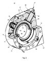
- the bearing unit 01 is used to hold a cylinder 02 not shown here (see. Fig. 4 ), in particular printing cylinder 02, for example, forme cylinder 02 or blanket cylinder 02 of a printing press, in particular a web-fed rotary printing press, for example a web-fed rotary offset printing press.
- the printing unit cylinder 02 mounted in the bearing unit 01 can in particular be a printing cylinder 02 with a single cylinder channel on the circumference.
- the storage unit 01 can be fastened, for example, on a side frame of the printing press, z. B. screwed, it being understood that on both sides of the cylinder 02 each have a bearing unit 01 is provided.
- the bearing unit 01 comprises a bearing 03, for example, a roller bearing 03, with an axial bore 04 for receiving a pin 06 (see. Fig. 4 )
- the bearing 03 includes a bearing inner ring 08, which defines the bore 04, a bearing outer ring 09 which is rotatably received in the bearing housing 07, and a recorded between bearing inner ring 08 and bearing outer ring 09 Wälzoasasatz 10.
- the bearing housing 07 is firmly screwed through threaded holes 11 with a side frame of the printing press, not shown.
- the bearing outer ring 09 is received in the bore 14 of the bearing housing 07 with radial play.
- the bearing outer ring 09 has on both sides a radially outwardly extending flange 12 and a contact shoulder 12, which extends into a correspondingly shaped, adjoining the bore 14 recess 13 on the respective end outer side of the bearing housing 07.
- the bearing outer ring 09 in the bearing housing 07 in the radial direction, d. H. in a plane perpendicular to the bearing axis movable, but received immovably in the axial direction due to the double-acting axial sliding of the abutment shoulders 12.
- the radially outwardly extending abutment shoulders 12 additionally cause a stiffening of the bearing outer ring 09, which is advantageous in view of the bending stress of the bearing outer ring 09 by the actuators 26 described below.
- the bearing housing 07 is formed divisible and comprises two housing halves 16; 17, which are joined together by means of dowel pins 18 and are screwed together.
- the dividing plane of the two housing halves 16; Preferably, the bearing outer ring 09 is divided Peripheral portion 17 of the other housing half 17 is rectangular.
- the length L1 of the long side of the rectangular housing half 17 may in particular correspond to twice the radius R of the semicircular or semicircular housing half 16 and the length L2 of the short side of the rectangular housing half may in particular correspond to the simple radius R.
- the bearing 03 or the bearing outer ring 09 is mounted as explained above with play in the bore 14 of the bearing housing 07.
- a rotation 19 in the form of a torsionally stiff, but flexible securing plate 19 is provided, which is annular with a ring-like portion 21 and a plurality, in particular four radially outwardly extending cranked arms 22, which preferably extend from each other at an angle of 90 °, and are preferably oriented so that two of the arms 22 extend in the direction of the two corners of the rectangular housing half 17.
- the annular portion 21 of the locking plate 19 is secured by screws 23 on the bearing outer ring 09, while the cranked arms 22 are fixed by screws 24 on the bearing housing 07, whereby a rotation 19 of the bearing outer ring 09 is created with simultaneous possibility of movement in the radial direction.
- each actuator 26 In the rectangular housing half 17 of the bearing housing 07 are two piezoelectric actuators 26, z. As actuators 26, for example, two piezo stack actuators 26 with integrated force plate arranged. The actuators 26 are completely received within the bearing housing 07. The actuators 26 extend The plane of each actuator 26 preferably extends perpendicular to the axis of the bearing 03 or the axis of the bearing 03 is preferably in the defined by the respective actuator 26 Level.
- the two actuators 26 are arranged at an angle of 90 ° + f 10% to each other, preferably 90 ° +/- 3%, in particular of 90 ° to each other, so in each case each have a vertical direction of action.
- the actuators 26 act with their radially inner end on the bearing outer ring 09 in the sense of moving the bearing outer ring 09 and thus the entire bearing 03 in a radial plane and are supported at its radially outer end on the bearing housing 07.
- a linear guide 29, z. B. a flat cage guide 29, in particular a needle rollers or balls having needle roller flat cage 29 may be provided.
- the two outer corner portions 27 of the rectangular housing half 17 are formed as detachable from the bearing housing 07 caps 27, in which the rear ends of the actuators 26 are encapsulated and supported by synthetic resin.
- the caps 27 in turn are fastened by means of screws 28 to the rectangular housing half 17.
- the actuators 26 via the actuators 26, the forces are directly over the stiffened by the flanges 12 bearing outer ring 09 in the center plane (therefore no torque input by Aktorkraft ) of the rigid bearing point initiated (the central axis of the actuator 27 is within the Wälz Scientificbachn and / or the working width of the rolling bearing 03); the actuators 26 are based on the bearing housing 07 directly from the rigid side frame of the printing press; to compensate for length or angle tolerances, the actuators 26 on the front side in each case an intermediate element 29 for transverse force coupling to the z. B. needle rollers having flat cage guide 29 is pressed and the back is set on each a spacer between the cap 27 and the bearing housing 07, an adhesive gap, which is poured with epoxy resin.
- the two actuators 26 opposite, preferably diametrically opposite each a biasing means 31 is provided which counteracts the force of the actuators 26.
- the biasing device 31 may in particular be formed by a spring device 31, for example by a cup spring assembly 31, which is arranged in the half-round housing half 16, radially aligned, is supported with its radially outer rear side on the housing half 16 and with its radially inner front acting on the bearing outer ring 09, wherein for decoupling of transverse forces turn a flat cage guide 29 may be provided.
- the biasing force of each spring means 31 is adjusted so that the spring means 31 biases its associated piezoelectric actuator 26 with a force corresponding to half the maximum actuating force of the control element 26.
- the method for reducing oscillation amplitudes of the bending modes of a printing cylinder 02 is, generally speaking, essentially that at least one bearing point of the printing cylinder 02, preferably at both or all bearing points, a dynamic capac Vietnamese pursebung occurs.
- This dynamic capacticianverschiebung takes place in particular by means of at least one piezoelectric Actuator 26 and Aktors 26th
- the actuators 26 by means of a suitable control or regulation, as in principle, for example, from the above-mentioned WO 2006/061432 A1 is known, energized in the required manner to initiate a force in the bearing 03, which counteracts the forces acting on the mounted cylinder 02 forces, for example when rolling over a clamping channel, or compensates for this, to avoid vibration excitations as possible.
- the existing clearance or gap between the radially outer bearing outer race 09 and the bore 14 of the bearing housing 07 restricts the maximum deflection of the actuators 26 in the event of overload (eg, in a winder) and thus prevents destruction and / or depolarization the actuators 26 in case of overload.
- the arrangement of the actuators 26 explained above also leads to an avoidance of transverse forces or bending moments on the actuators 26.
- an optimal gap between the outer ring and housing is required, which is large enough to the maximum Aktorhub (here about 45 microns) - taking into account manufacturing / assembly tolerances - to realize, is small enough to limit the maximum Aktoreinfederung (permissible (F.max-F.block) * C.aktor, here about 32 microns in ideal rigid environment).
- the gap was here dimensioned to 65 microns.
- the game is preferably 10 - 500 microns, in particular 20 - 100 microns.
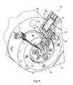
- the second embodiment according to Fig. 4 and 5 is essentially the same as in Fig. 1 to 3 , However, additionally has a built-in storage unit 01 side register adjustment device 32, the axial displacement of the printing cylinder 02, z. B. forme cylinder 02, in particular plate cylinder 02 for Correction of the page register enabled.
- the pin 06 of the forme cylinder 02 is non-rotatably connected to a pin extension 33, which carries a further bearing 34, namely a thrust bearing 34, for example a thrust ball bearing 34, the housing 36 at its outer periphery with a thread 37, in particular a fine thread 37,
- a metric fine thread 37 is provided, which meshes with a corresponding thread 38 of a fixed flange 39 which is rotatably connected to the bearing outer ring 09, in particular screwed.
- a rotation of the housing 36 of the thrust bearing 34 thus causes an axial translational movement of the housing 36 and thus ultimately of the cylinder 02.
- the possible adjustment range here can be about +/- 1.5 mm.
- a ring gear 41 is further mounted, which is rotatable via an additional drive gear 42, in particular spur gear 42 via a drive shaft 43 to the o. G.
- additional drive gear 42 in particular spur gear 42 via a drive shaft 43 to the o. G.
- p is the pitch of the thread 37
- d m is the mean thread diameter
- bearing unit 01 as a rubber cylinder bearing
- the integration of a macroscopic position adjustment for pressure and rest position of the blanket cylinder 02 is possible, see. also WO 2006/061432 A1 ,
Description
Die Erfindung betrifft Lagereinheiten für einen Druckwerkszylinder einer Druckmaschine gemäß dem Oberbegriff des Anspruchs 1.The invention relates to storage units for a printing cylinder of a printing press according to the preamble of claim 1.
Bei Druckmaschinen, insbesondere auch Rollenrotationsoffsetdruckmaschinen, führt der Wunsch der Anwender nach erhöhter Flexibilität basierend auf einem kleinen Seitensprung, was zu Einfachumfang-Plattenzylindern führt, bei gleichzeitig hoher Produktivität, was zu mehrfachbreiten Druckmaschinen führt, zu vergleichsweise biegeweichen Druckzylindern und damit zu Maschinenkonzepten mit potenziell hoher Anfälligkeit gegen Schwingungsstreifen im Druckbild.In printing presses, especially web offset rotary presses, users' desire for increased flexibility based on a small flipping, resulting in single-circumference plate cylinders, coupled with high productivity, resulting in multi-width presses, leads to relatively flexible pressure cylinders and thus to potentially high-end machine concepts Susceptibility to vibration stripes in the printed image.
In der Literatur sind diverse Verfahren zur Reduzierung der Biegedeformation von rotatorischen Bauteilen zu finden. Die einzelnen Verfahren lassen sich in passive Verfahren und in aktive Verfahren unterscheiden. Im Gegensatz zu passiven Verfahren, z. B. konstruktiven, zeitlich konstanten Maßnahmen wie beispielsweise Reduktion der Kanalschlagkraft durch Verwendung besonders schmaler Zylinderkanäle, sog. "Minigaps" oder durch Sleeves am Gummizylinder, wird bei aktiven Verfahren abhängig vom Maschinenzustand, zeitlich veränderlich und unter Verwendung zusätzlicher Energie, in geeigneter Weise eingegriffen. Aktive Verfahren können entsprechend ihrer Wirkungsweise in statische und dynamische Verfahren untergliedert werden. Bei statischen Systemen werden die Stellglieder in längeren Zeitskalen aktualisiert, um veränderten Randbedingungen, wie z. B. Produktionswechsel, andere Verbrauchsstoffe oder temperaturbedingte Veränderungen, zu kompensieren. Dynamische Verfahren hingegen weisen deutlich geringere Zykluszeiten (im Bereich der Eigenfrequenzen relevanter Schwingungsmoden) auf, um dem dynamischen Schwingungsverhalten über Aktoren entgegenzuwirken. Die vorliegende Erfindung beschäftigt sich mit einem aktiven Verfahren zur dynamischen Reduktion der Biegeschwingungsamplituden.Various methods for reducing the bending deformation of rotary components can be found in the literature. The individual methods can be differentiated into passive methods and active methods. In contrast to passive methods, eg. B. constructive, temporally constant measures such as reducing the channel impact force by using very narrow cylinder channels, so-called. "Minigaps" or sleeves on the blanket cylinder, is intervened in active method depending on the machine condition, temporally variable and using additional energy in a suitable manner. Active methods can be subdivided according to their mode of action into static and dynamic methods. In static systems, the actuators are updated in longer time scales to change the boundary conditions, such. B. change of production, other consumables or temperature-related changes to compensate. By contrast, dynamic methods have significantly shorter cycle times (in the range of the natural frequencies of relevant vibration modes) in order to counteract the dynamic vibration behavior via actuators. The present invention is concerned with an active Method for the dynamic reduction of the bending vibration amplitudes.
Im Falle der
Aus der
Die vorstehend beschriebenen Verfahren zur aktiven Schwingungsdämpfung sind fast ausschließlich zur Dämpfung resonant erzwungener Schwingungen in Werkzeugmaschinen in Gebrauch, wo eine kontinuierliche Anregung (Unwucht, Rattermarken, Prozesskräfte) vorliegt. Hierbei reichen zur Dämpfung bereits geringe, kontinuierlich eingebrachte Kräfte aus, die aus einer messtechnischen Erfassung des Istwertes und einem Regelalgorithmus abgeleitet werden.The active vibration damping techniques described above are almost exclusively used for damping resonantly forced vibrations in machine tools where there is continuous excitation (imbalance, chatter marks, process forces). In this case, low, continuously introduced forces are sufficient for damping, which are derived from a metrological detection of the actual value and a control algorithm.
Im Gegensatz dazu entstehen die Kanalschlag-Schwingungen von Druckzylindern durch eine einmalige pro Umdrehung oder periodische, pulsförmige Anregung. Die Kraftanregung erfolgt durch Wegfall bzw. Reduktion der Andrückkraft bei Überrollung der Unterbrechung der Mantelfläche (z. B. Spannkanal der Öffnung zur Aufnahme von einem Aufzug). Aufgrund der sehr kurzzeitig wirkenden Schlaganregung und der Forderung, bereits die erste Schwingung nahezu vollständig zu unterdrücken, die andernfalls bereits als Qualitätsmangel im Druckprodukt sichtbar wäre, werden neue Konzepte bzgl. Aktorik und Ansteuerung erforderlich.In contrast, the channel impact vibrations of printing cylinders are caused by a single per revolution or periodic, pulse-shaped excitation. The force is applied by eliminating or reducing the pressing force when the interruption of the lateral surface is overrun (eg clamping channel of the opening for receiving an elevator). Due to the very short-term impact stimulus and the requirement to almost completely suppress the first vibration, which would otherwise already be visible as a quality defect in the printed product, new concepts regarding actuator technology and control are required.
Befindet sich die Aktorik im Druckzylinder, führt das zu hohen Fertigungs- und Montagekosten und darüber hinaus zu Problemen durch die Zylinderrotation, beispielsweise Problemen im Zusammengang mit dann erforderlichen Drehdurchführungen oder im Zusammenhang mit Elektronik und Aktorik, die hohen Zentrifugalbeschleunigungen bis maximal dem 350 bis 400-fachen der Erdbeschleunigung ausgesetzt sind.If the actuators are located in the impression cylinder, this leads to high manufacturing and assembly costs and, in addition, to cylinder rotation problems. For example, problems in connection with then required rotary unions or in connection with electronics and actuators, the high centrifugal accelerations are exposed to a maximum of 350 to 400 times the gravitational acceleration.
Ein zusätzliches Lager im Abstand zum Maschinenlager zur Biegemomenteinleitung führt zu zahlreichen technischen Problemen, wie z. B. zu geringe Steifigkeit des Lagerzapfens für Momenteinleitung und dadurch hohe erforderliche Hübe und damit auch Baulänge der Aktorik und Kollision mit benachbarten Baugruppen wie Seitenregister oder Antrieb.An additional bearing at a distance from the machine bearing for bending moment introduction leads to numerous technical problems, such. B. too low rigidity of the bearing pin for torque introduction and thus high required strokes and thus length of the actuators and collision with adjacent assemblies such as page register or drive.
Aus der
Aus der
Der Erfindung liegt die Aufgabe zugrunde, Lagereinheiten für einen Druckwerkszylinder einer Druckmaschine zu schaffen.The invention has for its object to provide storage units for a printing cylinder of a printing press.
Die Aufgabe wird erfindungsgemäß durch die Merkmale des Anspruchs 1 gelöst.The object is achieved by the features of claim 1.
Die mit der Erfindung erzielbaren Vorteile bestehen insbesondere darin, dass während des Druckbetriebes mittels einer geeigneten Aktorik, d. h. mittels der piezoelektrischen Stellelemente bzw. Piezoaktoren, an den Lagerstellen des Druckwerkszylinders eine Kraft eingeleitet werden kann, die den Wegfall bzw. die Verringerung der Druckspannung beim Überrollen eines Zylinderkanals, beispielsweise eines Spannkanals eines Plattenzylinders, kompensiert und somit eine Schwingungsanregung vermeidet. Zu diesem Zweck werden mittels der Piezoaktoren über das Lager in den Druckwerkszylinder Radialkräfte eingeleitet, die in Größe und Wirkungsdauer der Kanalschlagkraft im Wesentlichen entsprechen. Gilt zu jedem Zeitpunkt, dass die Summe von Kanalschlagkraft und Aktorkraft gleich Null ist, so kann eine Bewegung des Zylinderschwerpunktes vermieden werden.The achievable with the present invention consist in particular that during the printing operation by means of a suitable actuator, d. H. By means of the piezoelectric adjusting elements or piezoelectric actuators, at the bearing points of the printing cylinder, a force can be introduced which compensates for the elimination or reduction of the compressive stress when rolling over a cylinder channel, for example a clamping channel of a plate cylinder, and thus avoids vibration excitation. For this purpose, radial forces are introduced by means of the piezo actuators via the bearing in the printing cylinder, which substantially correspond in size and duration of action of the channel impact force. If the sum of the channel impact force and the actuator force is equal to zero at any time, movement of the center of gravity of the cylinder can be avoided.
Die Erfindung ermöglicht eine Integration einer geeigneten Aktorik zur Verschiebung des Lagermittelpunktes des Druckwerkszylinders und eines geeigneten Messsystems zur Berechnung der Aktorstellkurve in eine vormontierte, kompakte Lagereinheit, die den Anforderungen hinsichtlich Bauraum und Anschlusskonstruktionen eines Druckwerkszylinders in einer Druckmaschine genügt.The invention enables integration of a suitable actuator for moving the bearing center of the printing cylinder and a suitable measuring system for calculating the Aktorstellkurve in a pre-assembled, compact storage unit that meets the requirements for space and connecting structures of a printing cylinder in a printing press.
Die kompakte und montagefreundliche Lagereinheit, die vormontiert, eingestellt, z. B. per Schrumpfsitz auf den Wellensitz des Druckwerkszylinders montiert und komplett mit dem Druckwerkszylinder an ein Seitengestell der Druckmaschine montiert wird, führt zu keinerlei Kollision mit benachbarten Baugruppen wie Seitenregister oder Antrieb; die Aktoren und die Leistungselektronik sind am Lagergehäuse, also an feststehenden Bauteilen angebracht.The compact and easy-to-install bearing unit, which is pre-assembled, adjusted, eg B. mounted by shrink fit on the shaft seat of the printing cylinder and is mounted completely with the printing cylinder to a side frame of the printing press, resulting in no collision with adjacent modules such as page register or drive; The actuators and the power electronics are mounted on the bearing housing, ie on fixed components.
Durch die insbesondere orthogonale Wirkrichtungen der vorzugsweise zwei Aktoren werden Verschiebungen des Lagermittelpunktes in einer Ebene senkrecht zur Zylinderachse ermöglicht die Lagereinheiten sind somit für verschiedene Druckwerkstypen (Zylinderwinkel bzw. Kanalschlagrichtung) einsetzbar.By the particular orthogonal effective directions of preferably two actuators shifts of the bearing center point in a plane perpendicular to the cylinder axis allows the bearing units are thus for different types of printing units (cylinder angle or channel strike direction) can be used.
Bei den gegenwärtig typischen Druckwerkbelastungen sind Aktorabmessungen erforderlich, die in der bevorzugten Querschnittsform der Lagereinheit, also Vorspannungsseite abgerundet und Aktorseiten eckig, eingebaut werden können. Die wirksame Aktorlänge kann somit auf ca. 50% des Zylinderradius gesteigert werden. Nachdem bei Piezoaktoren der Hub proportional zur wirksamen Länge ist, können Aktoren relevanter Größe verbaut werden, wobei dennoch ausreichend Bauraum für Radiallager gewährleistet ist.Actuator dimensions are required in the currently typical printing unit loads, which can be rounded off in the preferred cross-sectional shape of the bearing unit, that is to say the preload side is rounded and the actuator sides are square. The effective actuator length can thus be increased to approximately 50% of the cylinder radius. After the stroke is proportional to the effective length of piezo actuators Actuators relevant size can be installed, while still sufficient space for radial bearings is guaranteed.
Im Falle der vorliegenden Erfindung ist somit eine Integration von Aktorik und Sensorik in eine kompakte Baueinheit in Form einer Lagereinheit möglich, unter maximaler Ausnutzung des zur Verfügung stehenden Bauraums. Im Falle eines Plattenzylinders beispielsweise einer Rollenrotationsdruckmaschine, beispielsweise einer Rollenrotationsoffsetdruckmaschine ergibt sich die Bauraumbeschränkung in radialer Richtung im Wesentlichen aus der Forderung, mehrere Farb- bzw. Feuchtauftragswalzen mit entsprechenden Verstellmechanismen um die Mantelfläche des Plattenzylinders herum anbringen zu können und zwischen Plattenzylinder und Gummizylinder den erforderlichen Achsabstand einzuhalten.In the case of the present invention, an integration of actuators and sensors in a compact unit in the form of a storage unit is thus possible, with maximum utilization of the available installation space. In the case of a plate cylinder, for example, a web-fed rotary printing press, such as a web-fed rotary offset printing machine, the space constraint in the radial direction essentially results from the requirement to be able to apply several inking or dampening rollers with corresponding adjustment mechanisms around the outer surface of the plate cylinder and between plate cylinder and blanket cylinder the required center distance observed.
Gemäß einer bevorzugten Weiterbildung der Erfindung kann die Lagereinheit eine Seitenregister-Verstelleinrichtung umfassen, die ein Axiallager zum axialen Verstellen des in der Lagereinheit aufgenommenen Druckwerkszylinders umfassen kann, welches mittels einer Gewindeeinrichtung verstellbar sein kann. Eine solche Lagereinheit eignet sich insbesondere auch zur Verwendung im Zusammenhang mit Plattenzylindern.According to a preferred embodiment of the invention, the bearing unit may comprise a side register adjustment device, which may include a thrust bearing for axially adjusting the recorded in the storage unit printing cylinder, which may be adjustable by means of a threaded device. Such a storage unit is particularly suitable for use in connection with plate cylinders.
Ausführungsbeispiele der Erfindung sind in den Zeichnungen dargestellt und werden im Folgenden näher beschrieben.Embodiments of the invention are illustrated in the drawings and will be described in more detail below.
Es zeigen:
- Fig. 1
- eine perspektivische Ansicht einer Lagereinheit, mit Blickrichtung auf die Kontaktfläche zum Seitengestell der Druckmaschine;
- Fig. 2
- die Lagereinheit gemäß
Fig. 1 teilweise im Schnitt; - Fig. 3
- die Lagereinheit gemäß
Fig. 1 und2 , von der anderen Seite, also mit Blickrichtung von der Zylinderstirnfläche gesehen und teilweise im Schnitt; - Fig. 4
- eine perspektivische Teilansicht einer weiteren Ausführungsform einer Lagereinheit samt Zylinder, teilweise im Schnitt;
- Fig. 5
- eine Schnittansicht der Anordnung gemäß
Fig. 4 .
- Fig. 1
- a perspective view of a storage unit, looking towards the contact surface to the side frame of the printing machine;
- Fig. 2
- the storage unit according to
Fig. 1 partly in section; - Fig. 3
- the storage unit according to
Fig. 1 and2 , seen from the other side, so viewed from the cylinder face and partially in section; - Fig. 4
- a partial perspective view of another embodiment of a storage unit together with cylinder, partially in section;
- Fig. 5
- a sectional view of the arrangement according to
Fig. 4 ,
Zunächst wird auf die erste Ausführungsform nach den
Die Lagereinheit 01 umfasst ein Lager 03, beispielsweise ein Wälzlager 03, mit einer axialen Bohrung 04 zur Aufnahme eines Zapfens 06 (vgl.
Der Lageraußenring 09 ist in der Bohrung 14 des Lagergehäuses 07 mit radialem Spiel aufgenommen. Der Lageraußenring 09 weist beidseitig einen sich radial nach außen erstreckenden Flansch 12 bzw. eine Anlageschulter 12 auf, die sich in eine entsprechend geformte, an die Bohrung 14 anschließende Ausnehmung 13 an der jeweiligen stirnseitigen Außenseite des Lagergehäuses 07 erstreckt. Auf diese Weise ist der Lageraußenring 09 im Lagergehäuse 07 in radialer Richtung, d. h. in einer Ebene senkrecht zur Lagerachse beweglich, in axialer Richtung aufgrund der beidseitig wirkenden axialen Gleitführung der Anlageschultern 12 jedoch unverschieblich aufgenommen. Die sich radial nach außen erstreckenden Anlageschultern 12 bewirken zusätzlich eine Versteifung des Lageraußenrings 09, was in Hinblick auf die Biegebeanspruchung des Lageraußenrings 09 durch die weiter unten beschriebenen Aktoren 26 von Vorteil ist.The bearing
Das Lagergehäuse 07 ist teilbar ausgebildet und umfasst zwei Gehäusehälften 16; 17, die mittels Passstiften 18 zusammenfügbar sind und miteinander verschraubbar sind. Die Teilungsebene der beiden Gehäusehälften 16; 17 verläuft vorzugsweise durch die Achse der Lagereinheit 01. (Alternativ kann auch der Lageraußenring 09 geteilt sein.) Die Außenkontur der einen Gehäusehälfte 16 ist halbkreisförmig, erstreckt sich also über einen Umfangsabschnitt 16 von 180°, während die Außenkontur bzw. der Umfangsabschnitt 17 der anderen Gehäusehälfte 17 rechteckig ist. Die Länge L1 der langen Seite der rechteckförmigen Gehäusehälfte 17 kann insbesondere dem doppelten Radius R der halbkreisförmigen bzw. halbrunden Gehäusehälfte 16 entsprechen und die Länge L2 der kurzen Seite der rechteckförmigen Gehäusehälfte kann insbesondere dem einfachen Radius R entsprechen. Die Lagereinheit 01 wird im Zusammenhang mit einem Zylinder 02 mit einem Außendurchmesser D verwendet, wobei vorzugsweise die Beziehungen L1 < oder = D sowie R < oder = D/2 gelten. Hierdurch ergeben sich eine besonders kompakte und einbaufreundliche Bauweise der Lagereinheit 01 sowie ausreichend Platz für periphere Komponenten wie beispielsweise Farbauftragswalzen im Falle einer Verwendung der Lagereinheiten 01 im Zusammenhang mit Formzylindern 02.The bearing
Das Lager 03 bzw. der Lageraußenring 09 ist wie oben erläutert mit Spiel in der Bohrung 14 des Lagergehäuses 07 gelagert. Um das Lager 03, d. h. den Lageraußenring 09 relativ zum Lagergehäuse 07 winkelmäßig fixiert, aber in einer Ebene senkrecht zur Lagerachse beweglich zu halten, ist eine Verdrehsicherung 19 in Form eines torsionssteifen, aber biegeweichen Sicherungsblechs 19 vorgesehen, welches ringartig ausgebildet ist mit einem ringartigen Abschnitt 21 und mehreren, insbesondere vier sich radial nach außen erstreckenden gekröpften Armen 22, die sich zueinander vorzugsweise jeweils unter einem Winkel von 90° erstrecken und vorzugsweise so ausgerichtet sind, dass zwei der Arme 22 sich in Richtung der beiden Ecken der rechteckförmigen Gehäusehälfte 17 erstrecken. Der ringförmige Abschnitt 21 des Sicherungsblechs 19 ist über Schrauben 23 am Lageraußenring 09 befestigt, während die gekröpften Arme 22 über Schrauben 24 am Lagergehäuse 07 fixiert sind, wodurch eine Verdrehsicherung 19 des Lageraußenrings 09 bei gleichzeitiger Möglichkeit einer Bewegung in radialer Richtung geschaffen wird.The bearing 03 or the bearing
In der rechteckförmigen Gehäusehälfte 17 des Lagergehäuses 07 sind zwei piezoelektrische Stellelemente 26, z. B. Aktoren 26, beispielsweise zwei Piezo-Stackaktoren 26 mit integrierter Kraftmessscheibe, angeordnet. Die Aktoren 26 sind vollständig innerhalb des Lagergehäuses 07 aufgenommen. Die Aktoren 26 erstrecken sich mit ihrer Längsausdehnung in radialer Richtung sowie in Richtung der außenliegenden Ecken der rechteckförmigen Gehäusehälfte 17. Die Ebene eines jeden Aktors 26 erstreckt sich vorzugsweise senkrecht zur Achse des Lagers 03 oder aber die Achse des Lagers 03 liegt vorzugsweise in der durch den jeweiligen Aktor 26 definierten Ebene.In the
Die beiden Aktoren 26 sind zueinander unter einem Winkel von 90° +f 10%, vorzugsweise 90° +/- 3%, insbesondere von 90°, angeordnet, weisen also zueinander jeweils eine senkrechte Wirkrichtung auf. Die Aktoren 26 wirken mit ihrem radial innen liegenden Ende auf den Lageraußenring 09 im Sinne eines Bewegens des Lageraußenrings 09 und somit des gesamten Lagers 03 in einer radialen Ebene ein und sind an ihrem radial außen liegenden Ende am Lagergehäuse 07 abgestützt. Um eine Entkopplung von Querkräften zu erzielen, kann beispielsweise eine Linearführung 29, z. B. eine Flachkäfigführung 29, insbesondere ein Nadelrollen oder Kugeln aufweisende Nadelrollenflachkäfig 29 vorgesehen sein.The two
Die beiden außenliegenden Eckabschnitte 27 der rechteckförmigen Gehäusehälfte 17 sind als vom Lagergehäuse 07 lösbare Kappen 27 ausgebildet, in denen die rückwärtigen Enden der Aktoren 26 mittels Kunstharzes vergossen und abgestützt sind. Die Kappen 27 ihrerseits sind mittels Schrauben 28 an der rechteckförmigen Gehäusehälfte 17 befestigbar.The two
Nachdem hohe dynamische Kräfte in das Lager 03 eingeleitet werden müssen, ist ein kurzer Kraftpfad und eine steife Anbindung von großer Bedeutung: über die Aktoren 26 werden die Kräfte direkt über den durch die Flansche 12 versteiften Lageraußenring 09 in die Mittelebene (daher keine Drehomenteinleitung durch Aktorkraft) der steifen Lagerstelle eingeleitet (die Mittelachse des Aktors 27 liegt innerhalb der Wälzkörperbreiten und/oder der Arbeitsbreite des Wälzlagers 03); die Aktoren 26 stützen sich über das Lagergehäuse 07 direkt am steifen Seitengestell der Druckmaschine ab; zum Ausgleich von Längen- bzw. Winkeltoleranzen werden die Aktoren 26 vorderseitig jeweils ein Zwischenelement 29 zur Querkraftankopplung auf die z. B. Nadelrollen aufweisende Flachkäfigführung 29 angedrückt und rückseitig wird über jeweils eine Distanzscheibe zwischen der Kappe 27 und dem Lagergehäuse 07 ein Klebespalt eingestellt, der mit Epoxydharz ausgegossen wird.After high dynamic forces must be introduced into the
Querkräfte führen zur Zerstörung des Piezostacks. Nachdem die unter 90° angeordneten Aktoren 26 die Bewegung in der Ebene ermöglichen, somit aber auch Verschiebungen des Außenringes orthogonal zur Aktormittelachse auftreten, ist hier durch eine geeignete Linearführung 29 (vorzugsweise Nadelrollenflachkäfige 29) eine Entkoppelung zu schaffen.Transverse forces lead to the destruction of the piezo stack. After the actuators arranged at 90 ° allow the movement in the plane, but thus also displacements of the outer ring occur orthogonal to the actuator center axis, here by a suitable linear guide 29 (preferably Nadelrollenflachkäfige 29) to provide decoupling.
Den beiden Aktoren 26 gegenüberliegend, vorzugsweise diametral gegenüberliegend ist jeweils eine Vorspannungseinrichtung 31 vorgesehen, die der Kraft der Aktoren 26 entgegenwirkt. Die Vorspannungseinrichtung 31 kann insbesondere von einer Federeinrichtung 31, beispielsweise von einem Tellerfederpaket 31 gebildet sein, welches in der halbrunden Gehäusehälfte 16 angeordnet ist, radial ausgerichtet ist, sich mit seiner radial außen liegenden Rückseite an der Gehäusehälfte 16 abstützt und mit seiner radial innen liegenden Vorderseite auf den Lageraußenring 09 einwirkt, wobei zur Entkopplung von Querkräften wiederum eine Flachkäfigführung 29 vorgesehen sein kann. Vorzugsweise ist die Vorspannkraft einer jeden Federeinrichtung 31 so eingestellt, dass die Federeinrichtung 31 das ihr zugeordnete piezoelektrische Stellelement 26 mit einer Kraft vorspannt, die der halben maximalen Stellkraft des Stellelements 26 entspricht.The two
Das Verfahren zum Reduzieren von Schwingungsamplituden der Biegeeigenformen eines Druckwerkszylinders 02 besteht, allgemein gesprochen, im Wesentlichen darin, dass an mindestens einer Lagerstelle des Druckwerkszylinders 02, vorzugsweise an beiden bzw. allen Lagerstellen, eine dynamische Fußpunktverschiebung erfolgt. Diese dynamische Fußpunktverschiebung erfolgt insbesondere mittels mindestens eines piezoelektrischen Stellelements 26 bzw. Aktors 26.The method for reducing oscillation amplitudes of the bending modes of a
Im Betrieb werden die Aktoren 26 mittels einer geeigneten Steuerung bzw. Regelung, wie sie grundsätzlich beispielsweise aus der eingangs genannten
Allerdings können die unterschiedlichen Kraftangriffspunkte zu einer Biegedeformation des flexiblen Zylinders 02 um den Schwerpunkt führen. Während somit die Grundschwingung mit ihrem Maximum in der Mitte des Ballens des Zylinders 02 vollständig kompensiert werden kann, kann durch die vorgesehene Aktorik die zweite Oberschwingung, die ihr Maximum an den Lagerstellen hat, angeregt werden. Zu Lösung dieser Problematik kann hier vorzugsweise so vorgegangen werden, dass über eine geeignete Ansteuerung ein Kompromiss bzgl. der Amplituden aus beiden Eigenmoden angestrebt wird, vgl. auch
Das vorhandene Spiel bzw. der Spalt zwischen dem in einer radialen Ebene beweglichen Lageraußenring 09 und der Bohrung 14 des Lagergehäuses 07 beschränkt die maximale Einfederung der Aktoren 26 bei Überlast (z. B. bei einem Wickler) und verhindert so eine Zerstörung und/oder Depolarisierung der Aktoren 26 im Fall einer Überlast. Die oben erläuterte Anordnung der Aktoren 26 führt auch zu einer Vermeidung von Querkräften bzw. Biegemomenten auf die Aktoren 26.The existing clearance or gap between the radially outer bearing
Die auftretenden (hohen) Kräfte im Falle z. B. eines Papierwicklers führen zur Depolarisation des Aktors und damit den Aktor unbrauchbar machen würden. Somit ist ein optimaler Spalt zwischen Außenring und Gehäuse erforderlich, der groß genug ist um den maximalen Aktorhub (hier ca. 45 µm) - unter Berücksichtigung von Fertigungs-/Montagetoleranzen - zu realisieren, klein genug ist um die maximale Aktoreinfederung (zulässig (F.max-F.block)*C.aktor, hier ca. 32 µm bei ideal steifer Umgebung) zu begrenzen. Nachdem die Umbauteile eine endliche Steifigkeit besitzen, wurde der Spalt hier auf 65 µm dimensioniert. Das Spiel beträgt vorzugsweise 10 - 500 µm, insbesondere 20 - 100 µm.The occurring (high) forces in the case of z. As a paper winder lead to the depolarization of the actuator and thus make the actuator useless. Thus, an optimal gap between the outer ring and housing is required, which is large enough to the maximum Aktorhub (here about 45 microns) - taking into account manufacturing / assembly tolerances - to realize, is small enough to limit the maximum Aktoreinfederung (permissible (F.max-F.block) * C.aktor, here about 32 microns in ideal rigid environment). After the conversion parts have a finite rigidity, the gap was here dimensioned to 65 microns. The game is preferably 10 - 500 microns, in particular 20 - 100 microns.
Weitere Merkmale der Lösung sind in folgenden Punkten zusehen:
- steife Ankopplung der Aktoren 26
zwischen Zylinder 02 und Seitengestell (die Piezo-Stackaktoren 26 können als Feder mit Fußpunktanregung modelliert werden, d. h. jede zusätzliche Nachgiebigkeit reduziert die eingekoppelte Kraft); - geometrische Zusammenhänge Aktorlänge/Aktorhub vs. geringe Achsabstände (= Maximalgröße des Lagers) bei Einfachumfangmaschinen und Schwächung des Lagergehäuses 07 und ausreichend dimensioniertes Wälzlager 03;
- Sicherstellung der Lebensdauer des Zylinderlagers trotz zusätzlicher Aktorkräfte durch optimierte Gestaltung des Außenrings;
- die fertigungs- und montageoptimierte Gestaltung der Lagereinheit 01;
- die Möglichkeit der Ausführung der Lagereinheit 01 als Plattenzylinderlager mit integriertem Seitenregister (vgl. unten) und optimierter Außenkontur zur Anordnung von Farbwalzen.
- rigid coupling of the
actuators 26 betweencylinder 02 and side frame (thepiezo stack actuators 26 can be modeled as a spring with Fußpunktanregung, ie any additional compliance reduces the coupled force); - geometric relationships actuator length / actuator stroke vs. small center distances (= maximum size of the bearing) with single-circumference machines and weakening of the bearing
housing 07 and sufficientlysized bearings 03; - Ensuring the service life of the cylindrical bearing despite additional actuator forces through optimized design of the outer ring;
- the production and assembly-optimized design of the
storage unit 01; - the possibility of the execution of the bearing
unit 01 as a plate cylinder bearing with integrated side register (see below) and optimized outer contour for the arrangement of ink rollers.
Die zweite Ausführungsform gemäß
Am Gehäuse 36 des Axiallagers 34 ist des Weiteren ein Zahnkranz 41 montiert, der über ein zusätzliches Antriebszahnrad 42, insbesondere Stirnrad 42 über eine Antriebswelle 43 verdrehbar ist, um die o. g. Translationsbewegung des Zylinders 02 zu erzeugen.On the housing 36 of the
Selbst bei Annahme eines geringen Wirkungsgrades η = 20% der Getriebeübersetzungen ergibt sich ein günstiges Verhältnis zwischen Drehmoment M und Axialverschiebekraft Fax von ca. ![]()
![]()
Die Verzahnung wird hierbei als schiefe Ebene betrachtet, an der folgende Beziehungen für Kräfte und Winkel gelten: 
Und mit ![]()
gilt: 
And with ![]()
applies:
In den obigen Beziehungen bedeuten: p die Steigung des Gewindes 37, dm der mittlere Gewindedurchmesser und i das Übersetzungsverhältnis des Zahnradgetriebes (hier angenommen i=1:3,75). Um beispielsweise eine axiale Verschiebekraft von 1.000 N zu erzielen, ist ein Drehmoment von 0,42 Nm erforderlich.In the above relationships: p is the pitch of the
Wichtig anzumerken ist bei diesem Verstellmechanismus, dass der feststehende Flansch 39, in dem auch das Antriebzahnsrad 42 gelagert ist, fest mit dem durch die Aktorik beweglichen Lageraußenring 09 verbunden ist. Somit wird ein Klemmen der Verstelleinheit durch den Aktorhub vermieden.It should be noted important in this adjustment that the fixed
In einer weiterhin bevorzugten, nicht näher dargestellten Ausführung der Lagereinheit 01 als Gummizylinderlagerung ist die Integration einer makroskopischen Lageverstellung für Druck- und Ruheposition des Gummizylinders 02 möglich, vgl. auch
- 0101
- Lagereinheitstorage unit
- 0202
- Zylinder, Druckwerkszylinder, Formzylinder, Plattenzylinder, GummizylinderCylinder, printing cylinder, forme cylinder, plate cylinder, rubber cylinder
- 0303
- Lager, WälzlagerBearings, Rolling Bearings
- 0404
- Bohrung (03)Bore (03)
- 0505
- --
- 0606
- Zapfen (02)Cones (02)
- 0707
- Lagergehäusebearing housing
- 0808
- LagerinnenringBearing inner ring
- 0909
- LageraußenringBearing outer ring
- 1010
- Wälzkörpersatzrolling element
- 1111
- Gewindebohrungthreaded hole
- 1212
- Flansch, Anlageschulter (09)Flange, contact shoulder (09)
- 1313
- Ausnehmung (07)Recess (07)
- 1414
- Bohrung (07)Bore (07)
- 1515
- --
- 1616
- Gehäusehälfte, halbkreisförmig, UmfangsabschnittCase half, semicircular, peripheral portion
- 1717
- Gehäusehälfte, rechteckförmig, UmfangsabschnittCase half, rectangular, peripheral section
- 1818
- Passstiftdowel
- 1919
- Verdrehsicherung, SicherungsblechAnti-rotation lock, locking plate
- 2020
- --
- 2121
- Abschnitt, ringförmiger (19)Section, annular (19)
- 2222
- Arm (19)Arm (19)
- 2323
- Schraubescrew
- 2424
- Schraubescrew
- 2525
- --
- 2626
- Stellelement, Aktor, Piezo-StackaktorActuator, actuator, piezo stack actuator
- 2727
- Eckabschnitt, KappeCorner section, cap
- 2828
- Schraubenscrew
- 2929
- Linearführung, Zwischenelement, Flachkäfigführung, NadelrollenflachkäfigLinear guide, intermediate element, flat cage guide, needle roller flat cage
- 3030
- --
- 3131
- Vorspannungseinrichtung, Federeinrichtung, TellerfederpaketBiasing device, spring device, plate spring package
- 3232
- Seitenregister-VerstelleinrichtungSide register adjustment device
- 3333
- ZapfenverlängerungZapf extension
- 3434
- Lager, Axiallager, AxialschrägkugellagerBearing, Thrust Bearing, Thrust Angular Contact Ball Bearing
- 3535
- --
- 3636
- Gehäuse (34)Housing (34)
- 3737
- Gewinde, Feingewinde (36)Thread, fine thread (36)
- 3838
- Gewinde (39)Thread (39)
- 3939
- Flanschflange
- 4040
- --
- 4141
- Zahnkranzsprocket
- 4242
- Antriebszahnrad, StirnradDrive gear, spur gear
- 4343
- Antriebswelledrive shaft
- DD
- Aussendruchmesser (02)Outside diameter (02)
- RR
- Radius (16)Radius (16)
- L1L1
- Länge (17)Length (17)
- L2L2
- Länge (17)Length (17)
Claims (62)
- Bearing unit (01) for a printing unit cylinder (02) of a printing press, having a bearing (03) and a bearing housing (07), incorporating the bearing (03), the bearing (03) comprising a bearing outer ring (09), a bearing inner ring (08) and a roller body set (10) incorporated between the bearing outer ring (09) and bearing inner ring (08), and at least one piezoelectric control element (26) being provided between the bearing housing (07) and the bearing outer ring (09), the bearing outer ring (09) being movably arranged in the bearing housing (07) in a plane perpendicular to the axis of the bearing unit (01) in the printing operation of the printing press at least by means of the at least one piezoelectric control element (26), a side register adjusting device (32) being arranged in the bearing unit (01), characterised in that a transverse force-decoupling intermediate element (29) is arranged between the bearing outer ring (09) and the control element (26).
- Bearing unit according to Claim 1, characterised in that at least a part of the side register adjusting device (32) is movably arranged by means of the piezoelectric control element (26).
- Bearing unit according to Claim 1, characterised in that the bearing unit (01) comprises two piezoelectric control elements (26), which seen with respect to the bearing axis are arranged relative to one another at an angle of 90° +/- 10%.
- Bearing unit according to Claim 3, characterised in that the piezoelectric control elements (26) are arranged with respect to one another at an angle of 90° +/- 3%.
- Bearing unit according to Claim 1, characterised in that a spring device (31) is assigned to the at least one piezoelectric control element (26).
- Bearing unit according to Claim 5, characterised in that the spring device (31) is arranged opposite to the assigned piezoelectric control element (26).
- Bearing unit according to Claim 6, characterised in that the spring mechanism (31) is diametrically opposed to the assigned piezoelectric control element (26).
- Bearing unit according to Claim 5 or 6, characterised in that the spring device (31) is formed from a disc spring package (31).
- Bearing unit according to one of Claims 5 to 8, characterised in that the spring device (31) pretensions the piezoelectric control element (26) assigned to it with a force which corresponds to half the maximum control force of the control element (26).
- Bearing unit according to Claim 1, characterised in that the plane of the piezoelectric control element (26) extends perpendicularly to the axis of the bearing unit (01).
- Bearing unit according to Claim 1, characterised in that the central axis or force transmission lies in the same direction of the control element (26), preferably within the gap width of the roller body set (10).
- Bearing unit according to one of Claims 1 to 9, characterised in that the axis of the bearing unit (01) lies in the plane defined by the piezoelectric control element (26).
- Bearing unit according to Claim 1, characterised in that the piezoelectric control element (26) is included completely within the bearing housing (07).
- Bearing unit according to Claim 1, characterised in that the bearing housing (07) comprises several housing parts (16; 17).
- Bearing unit according to Claim 14, characterised in that the bearing housing (07) comprises two housing halves (16; 17).
- Bearing unit according to Claim 1, characterised in that the bearing housing (07) of the outer ring (09) is split.
- Bearing unit according to Claim 15, characterised in that a dividing plane of the two housing halves (16; 17) runs through the axis of the bearing unit (01).
- Bearing unit according to Claim 14, 15 or 17, characterised in that the two piezoelectric control elements (26) are arranged in one housing part (17) of the housing parts (16; 17) and the two spring devices (31) are arranged in the other housing part (16) of the housing parts (16, 17).
- Bearing unit according to one of Claims 15 to 18, characterised in that the two housing halves (16; 17) can be connected to one another by means of dowel pins (18).
- Bearing unit according to Claim 1, characterised in that the bearing housing (07) has a round housing half (16) seen in the direction of the axis and a further housing half (17) adjacent thereto.
- Bearing unit according to Claim 20, characterised in that the round housing half (16) extends over an angle range of preferably 180°.
- Bearing unit according to Claim 20 or 21, characterised in that the diameter (D) of a printing unit cylinder (02) incorporated by the bearing unit (01) corresponds to the diameter of the round housing half (16) or is smaller than this.
- Bearing unit according to Claim 15, characterised in that one housing half (16) of the two housing halves (16; 17) contains the round peripheral section (16) and the other housing half (17) contains the other peripheral section (17).
- Bearing unit according to Claim 5 and according to Claim 23, characterised in that the spring devices (31) are arranged in the housing half (16) with the round peripheral section (16) and the piezoelectric control elements (26) are arranged in the other housing half (17).
- Bearing unit according to Claim 24, characterised in that the other housing half (17) has an at least essentially rectangular peripheral section (17).
- Bearing unit according to Claim 20, characterised in that the other peripheral section (17) is at least essentially rectangular.
- Bearing unit according to Claim 25 or 26, characterised in that the length (L1) of the side of the rectangular peripheral section (17) opposite to the round peripheral section (16) corresponds to the diameter (D) of a printing unit cylinder (02) incorporated by the bearing unit (01) or is smaller than this.
- Bearing unit according to Claim 1, characterised in that the piezoelectric control element (26) is supported by means of a cap (27) on its rear side turned away from the bearing outer ring (09).
- Bearing unit according to Claim 28, characterised in that the cap (27) is designed as a detachable part of the bearing housing (07).
- Bearing unit according to Claim 28 or 29, characterised in that the rear of the piezoelectric control element (26) is cast in the cap (27).
- Bearing unit according to Claim 28 and according to Claim 26, characterised in that the cap (27) forms a corner section of the rectangular peripheral section (17) of the bearing housing (07).
- Bearing unit according to Claim 1, characterised in that the bearing unit (01) is designed to be fixable to a side frame of the printing press.
- Bearing unit according to Claim 32, characterised in that the bearing housing (07) is designed to be screwable to the side frame.
- Bearing unit according to Claim 1, characterised in that the bearing outer ring (09) is incorporated in the bearing housing (07) with radial play.
- Bearing unit according to Claim 34, characterised in that the play is 10 - 500 µm.
- Bearing unit according to Claim 34, characterised in that the play is 20 - 100 µm.
- Bearing unit according to Claim 1, characterised in that the bearing outer ring (09) is held securely against twisting on the bearing housing (07).
- Bearing unit according to Claim 37, characterised in that a torsionally stiff (19) securing plate (19) is provided, which, on the one hand is firmly connected to the bearing outer ring (09) and on the other hand to the bearing housing (07).
- Bearing unit according to Claim 38, characterised in that the securing plate (19) has an internal annular section (21) and arms (22) extending outwardly therefore.
- Bearing unit according to Claim 39, characterised in that the arms (22) are of cranked design.
- Bearing unit according to one of Claims 38 to 40, characterised in that the torsional securing plate (19) is pliable.
- Bearing unit according to Claim 1, characterised in that the bearing outer ring (09) has a radially outwardly extending flange (12) on its two axial ends.
- Bearing unit according to Claim 42, characterised in that the radially outwardly extending flange (12) is incorporated in a corresponding opening (13) of the bearing housing (07).
- Bearing unit according to Claim 1, characterised in that the side register adjusting device (32) comprises an axial bearing (34) for the axial adjustment of the printing unit cylinder (02) incorporated in the bearing unit (01).
- Bearing unit according to Claim 1, characterised in that the side register adjusting device (32) has a drive (37, 38).
- Bearing unit according to Claim 45, characterised in that the drive (37, 38) has a threading device.
- Bearing unit according to Claim 45, characterised in that the drive (37, 38) is movable by means of the piezoelectric control element (26).
- Bearing unit according to Claim 45, characterised in that the axial bearing (34) is adjustable by means of a threading device (37, 38).
- Bearing unit according to Claim 48, characterised in that an outer drive (37) of the axial bearing (34) engages with a drive (38) connected to the bearing outer ring (09).
- Bearing unit according to Claim 49, characterised in that a flange (39), on which the drive (38) is arranged, is rigidly fixed to the bearing outer ring (09).
- Bearing unit according to one of Claims 44 to 50, characterised in that the side register adjusting device (32) comprises a gear device (41, 42, 43) for axial adjustment.
- Bearing unit according to Claim 51, characterised in that the axial bearing (34) has a gear rim (41), which engages with a drive gearwheel (42).
- Bearing unit according to Claim 51 or 52, characterised in that the gearwheel device (41, 42, 43) comprises a drive shaft couplable to a drive (43).
- Bearing unit according to Claim 1, characterised in that the bearing unit (01) is designed as a bearing unit (01) of a plate cylinder (02).
- Bearing units according to Claim 1, characterised in that the bearing unit (01) is designed as a bearing unit (01) of a printing unit cylinder (02) with a single cylinder channel on the circumference.
- Bearing unit according to Claim 55, characterised in that the bearing unit (01) is designed as a bearing unit (01) of a printing unit cylinder (02), having a number of cylinder channels on the circumference.
- Bearing unit according to Claim 1, characterised in that the bearing unit (01) is designed as a bearing unit (01) for a printing unit cylinder (02) of a fed rotary printing press.
- Bearing unit according to Claim 1, characterised in that the intermediate element (29) contains needle rollers or balls.
- Bearing unit according to Claim 1, characterised in that the side register adjusting device (32) is integrated into the bearing unit (01).
- Bearing unit according to Claim 1, characterised in that at least parts of the side register adjusting device (32), together with the bearing unit (01) are separable and/or can be taken out of a side frame of the printing press.
- Bearing unit according to Claim 60, characterised in that at least the drive of the side register adjusting device (32), together with the bearing unit (01), are separable and/or can be taken out of a side frame of the printing press.
- Bearing unit according to Claim 1, characterised in that the bearing inner ring (08) is movable relative to the bearing outer ring (09) by means of the side register adjusting device (32).
Applications Claiming Priority (1)
| Application Number | Priority Date | Filing Date | Title |
|---|---|---|---|
| DE200710024767 DE102007024767B4 (en) | 2007-05-26 | 2007-05-26 | Bearing unit for a printing cylinder |
Publications (3)
| Publication Number | Publication Date |
|---|---|
| EP2006097A2 EP2006097A2 (en) | 2008-12-24 |
| EP2006097A3 EP2006097A3 (en) | 2012-01-11 |
| EP2006097B1 true EP2006097B1 (en) | 2012-10-24 |
Family
ID=39877254
Family Applications (1)
| Application Number | Title | Priority Date | Filing Date |
|---|---|---|---|
| EP20080152503 Not-in-force EP2006097B1 (en) | 2007-05-26 | 2008-03-10 | Bearing unit for a printing cylinder in a printing machine |
Country Status (2)
| Country | Link |
|---|---|
| EP (1) | EP2006097B1 (en) |
| DE (1) | DE102007024767B4 (en) |
Families Citing this family (5)
| Publication number | Priority date | Publication date | Assignee | Title |
|---|---|---|---|---|
| DE102009002899B3 (en) * | 2009-05-07 | 2010-06-24 | Koenig & Bauer Aktiengesellschaft | Axial adjusting device for cylinder of rotary printing machine, has motor and shear element pivoted around rotational axis by motor |
| DE102009046538B4 (en) | 2009-11-09 | 2014-06-05 | Koenig & Bauer Aktiengesellschaft | Devices and methods for vibration reduction |
| DE102010026204A1 (en) | 2010-07-02 | 2012-01-05 | Fakultät Ingenieurwissenschaften und Informatik Fachhochschule Onsabrück | Method for compensating periodically repeated disturbing excitations in periphery of e.g. roller system of rotary printing machine, involves producing forces for compensating excitations by annular profile provided in contact with component |
| CN103825396B (en) * | 2014-01-03 | 2016-08-17 | 重庆大学 | Electro spindle Active Vibration Control device |
| CN113531041B (en) * | 2021-07-30 | 2022-06-28 | 山东大学 | Stacked piezoelectric ceramic vibration damping ring |
Family Cites Families (8)
| Publication number | Priority date | Publication date | Assignee | Title |
|---|---|---|---|---|
| JPH11170474A (en) | 1997-12-05 | 1999-06-29 | Toshiba Mach Co Ltd | Shock mark preventing apparatus for printer |
| DE19963945C1 (en) | 1999-12-31 | 2001-07-19 | Koenig & Bauer Ag | Method and arrangement for compensating vibrations of rotating components |
| DE20011948U1 (en) | 2000-07-10 | 2000-12-07 | Skf Gmbh | Bearing arrangement |
| DE10107135A1 (en) * | 2001-02-15 | 2002-08-29 | Windmoeller & Hoelscher | Vibration damping in web-fed flexographic printing machine by applying damping forces to rollers in opposite direction to detected offsets |
| WO2004016431A1 (en) | 2002-07-19 | 2004-02-26 | Koenig & Bauer Aktiengesellschaft | Method and device for reducing vibrations on rotating parts, and vibration-damped rotating part |
| DE10236865A1 (en) * | 2002-08-12 | 2004-02-26 | Koenig & Bauer Ag | Print cylinder, forme cylinder or transfer cylinder for a print unit has an axial channel with a retaining device that holds the print forme in place and can be displaced along the channel be means of an actuator |
| EP1819513B1 (en) | 2004-12-10 | 2011-05-25 | Koenig & Bauer Aktiengesellschaft | Device for reducing vibration |
| DE102005058787B4 (en) * | 2004-12-10 | 2011-10-27 | Koenig & Bauer Aktiengesellschaft | Method and device for vibration reduction |
-
2007
- 2007-05-26 DE DE200710024767 patent/DE102007024767B4/en not_active Expired - Fee Related
-
2008
- 2008-03-10 EP EP20080152503 patent/EP2006097B1/en not_active Not-in-force
Also Published As
| Publication number | Publication date |
|---|---|
| EP2006097A2 (en) | 2008-12-24 |
| EP2006097A3 (en) | 2012-01-11 |
| DE102007024767A1 (en) | 2008-11-27 |
| DE102007024767B4 (en) | 2010-06-24 |
Similar Documents
| Publication | Publication Date | Title |
|---|---|---|
| EP1991419B1 (en) | Printing groups of a printing press | |
| EP2006097B1 (en) | Bearing unit for a printing cylinder in a printing machine | |
| EP1609908B1 (en) | Method and a device for reducing bending vibrations in rotating cylinder of a processing machine and processing machine | |
| EP1819513B1 (en) | Device for reducing vibration | |
| DE102005047661B4 (en) | Drive a rotating component of a printing press | |
| WO2022017720A1 (en) | Method and system for producing a gear unit | |
| EP1820643A2 (en) | Method for reducing vibrations | |
| EP3664998B1 (en) | Press | |
| EP1923214A2 (en) | Printing unit of a printing press with two double printing groups arranged one over the other | |
| DE102019121755A1 (en) | Multi-part actuator | |
| DE10327490B4 (en) | Printing unit of a rotary printing machine | |
| DE102005008982B3 (en) | Register-holding aligning device for printing plate has a register projection formed by cylindrical sector co-axial to cylindrical boring | |
| DE102005058787B4 (en) | Method and device for vibration reduction | |
| EP2762314B1 (en) | Rotation cylinder | |
| EP2782757A1 (en) | Flexographic printing unit with knee lever system | |
| DE4406572B4 (en) | Rotary press | |
| EP0771648A1 (en) | Device for taking up backlash in a printing machine | |
| DE102006003006B4 (en) | Method for setting a print on position | |
| DE102008041904B4 (en) | Method for controlling a rotation body setting | |
| WO2006015889A1 (en) | Devices for receiving a cylinder of a printing unit and corresponding printing unit | |
| DE102004022775B4 (en) | Arrangement of an electric motor for driving a rotating body | |
| WO2013029700A1 (en) | Printing press and printing-press cylinder supporting device | |
| DE102011082679B4 (en) | Device and method for fastening and / or adjusting a bearing device of a printing cylinder | |
| EP1923213A2 (en) | Printing unit of a printing press with two double printing groups arranged over each other | |
| DE102007025752A1 (en) | Powered assembly of a printing press |
Legal Events
| Date | Code | Title | Description |
|---|---|---|---|
| PUAI | Public reference made under article 153(3) epc to a published international application that has entered the european phase |
Free format text: ORIGINAL CODE: 0009012 |
|
| AK | Designated contracting states |
Kind code of ref document: A2 Designated state(s): AT BE BG CH CY CZ DE DK EE ES FI FR GB GR HR HU IE IS IT LI LT LU LV MC MT NL NO PL PT RO SE SI SK TR |
|
| AX | Request for extension of the european patent |
Extension state: AL BA MK RS |
|
| PUAL | Search report despatched |
Free format text: ORIGINAL CODE: 0009013 |
|
| AK | Designated contracting states |
Kind code of ref document: A3 Designated state(s): AT BE BG CH CY CZ DE DK EE ES FI FR GB GR HR HU IE IS IT LI LT LU LV MC MT NL NO PL PT RO SE SI SK TR |
|
| AX | Request for extension of the european patent |
Extension state: AL BA MK RS |
|
| RIC1 | Information provided on ipc code assigned before grant |
Ipc: B41F 13/26 20060101ALI20111206BHEP Ipc: B41F 13/24 20060101AFI20111206BHEP Ipc: B41F 13/30 20060101ALI20111206BHEP |
|
| 17P | Request for examination filed |
Effective date: 20111220 |
|
| GRAP | Despatch of communication of intention to grant a patent |
Free format text: ORIGINAL CODE: EPIDOSNIGR1 |
|
| RTI1 | Title (correction) |
Free format text: BEARING UNIT FOR A PRINTING CYLINDER IN A PRINTING MACHINE |
|
| GRAS | Grant fee paid |
Free format text: ORIGINAL CODE: EPIDOSNIGR3 |
|
| AKX | Designation fees paid |
Designated state(s): AT BE BG CH CY CZ DE DK EE ES FI FR GB GR HR HU IE IS IT LI LT LU LV MC MT NL NO PL PT RO SE SI SK TR |
|
| GRAA | (expected) grant |
Free format text: ORIGINAL CODE: 0009210 |
|
| AK | Designated contracting states |
Kind code of ref document: B1 Designated state(s): AT BE BG CH CY CZ DE DK EE ES FI FR GB GR HR HU IE IS IT LI LT LU LV MC MT NL NO PL PT RO SE SI SK TR |
|
| REG | Reference to a national code |
Ref country code: GB Ref legal event code: FG4D Free format text: NOT ENGLISH |
|
| REG | Reference to a national code |
Ref country code: CH Ref legal event code: EP |
|
| REG | Reference to a national code |
Ref country code: AT Ref legal event code: REF Ref document number: 580679 Country of ref document: AT Kind code of ref document: T Effective date: 20121115 |
|
| REG | Reference to a national code |
Ref country code: IE Ref legal event code: FG4D Free format text: LANGUAGE OF EP DOCUMENT: GERMAN |
|
| REG | Reference to a national code |
Ref country code: DE Ref legal event code: R096 Ref document number: 502008008477 Country of ref document: DE Effective date: 20121220 |
|
| REG | Reference to a national code |
Ref country code: NL Ref legal event code: VDEP Effective date: 20121024 |
|
| PG25 | Lapsed in a contracting state [announced via postgrant information from national office to epo] |
Ref country code: NL Free format text: LAPSE BECAUSE OF FAILURE TO SUBMIT A TRANSLATION OF THE DESCRIPTION OR TO PAY THE FEE WITHIN THE PRESCRIBED TIME-LIMIT Effective date: 20121024 Ref country code: FI Free format text: LAPSE BECAUSE OF FAILURE TO SUBMIT A TRANSLATION OF THE DESCRIPTION OR TO PAY THE FEE WITHIN THE PRESCRIBED TIME-LIMIT Effective date: 20121024 Ref country code: IS Free format text: LAPSE BECAUSE OF FAILURE TO SUBMIT A TRANSLATION OF THE DESCRIPTION OR TO PAY THE FEE WITHIN THE PRESCRIBED TIME-LIMIT Effective date: 20130224 Ref country code: NO Free format text: LAPSE BECAUSE OF FAILURE TO SUBMIT A TRANSLATION OF THE DESCRIPTION OR TO PAY THE FEE WITHIN THE PRESCRIBED TIME-LIMIT Effective date: 20130124 Ref country code: HR Free format text: LAPSE BECAUSE OF FAILURE TO SUBMIT A TRANSLATION OF THE DESCRIPTION OR TO PAY THE FEE WITHIN THE PRESCRIBED TIME-LIMIT Effective date: 20121024 Ref country code: SE Free format text: LAPSE BECAUSE OF FAILURE TO SUBMIT A TRANSLATION OF THE DESCRIPTION OR TO PAY THE FEE WITHIN THE PRESCRIBED TIME-LIMIT Effective date: 20121024 Ref country code: ES Free format text: LAPSE BECAUSE OF FAILURE TO SUBMIT A TRANSLATION OF THE DESCRIPTION OR TO PAY THE FEE WITHIN THE PRESCRIBED TIME-LIMIT Effective date: 20130204 |
|
| PG25 | Lapsed in a contracting state [announced via postgrant information from national office to epo] |
Ref country code: PL Free format text: LAPSE BECAUSE OF FAILURE TO SUBMIT A TRANSLATION OF THE DESCRIPTION OR TO PAY THE FEE WITHIN THE PRESCRIBED TIME-LIMIT Effective date: 20121024 Ref country code: GR Free format text: LAPSE BECAUSE OF FAILURE TO SUBMIT A TRANSLATION OF THE DESCRIPTION OR TO PAY THE FEE WITHIN THE PRESCRIBED TIME-LIMIT Effective date: 20130125 Ref country code: LV Free format text: LAPSE BECAUSE OF FAILURE TO SUBMIT A TRANSLATION OF THE DESCRIPTION OR TO PAY THE FEE WITHIN THE PRESCRIBED TIME-LIMIT Effective date: 20121024 Ref country code: CY Free format text: LAPSE BECAUSE OF FAILURE TO SUBMIT A TRANSLATION OF THE DESCRIPTION OR TO PAY THE FEE WITHIN THE PRESCRIBED TIME-LIMIT Effective date: 20121024 Ref country code: SI Free format text: LAPSE BECAUSE OF FAILURE TO SUBMIT A TRANSLATION OF THE DESCRIPTION OR TO PAY THE FEE WITHIN THE PRESCRIBED TIME-LIMIT Effective date: 20121024 Ref country code: PT Free format text: LAPSE BECAUSE OF FAILURE TO SUBMIT A TRANSLATION OF THE DESCRIPTION OR TO PAY THE FEE WITHIN THE PRESCRIBED TIME-LIMIT Effective date: 20130225 |
|
| PG25 | Lapsed in a contracting state [announced via postgrant information from national office to epo] |
Ref country code: DK Free format text: LAPSE BECAUSE OF FAILURE TO SUBMIT A TRANSLATION OF THE DESCRIPTION OR TO PAY THE FEE WITHIN THE PRESCRIBED TIME-LIMIT Effective date: 20121024 Ref country code: SK Free format text: LAPSE BECAUSE OF FAILURE TO SUBMIT A TRANSLATION OF THE DESCRIPTION OR TO PAY THE FEE WITHIN THE PRESCRIBED TIME-LIMIT Effective date: 20121024 Ref country code: BG Free format text: LAPSE BECAUSE OF FAILURE TO SUBMIT A TRANSLATION OF THE DESCRIPTION OR TO PAY THE FEE WITHIN THE PRESCRIBED TIME-LIMIT Effective date: 20130124 Ref country code: CZ Free format text: LAPSE BECAUSE OF FAILURE TO SUBMIT A TRANSLATION OF THE DESCRIPTION OR TO PAY THE FEE WITHIN THE PRESCRIBED TIME-LIMIT Effective date: 20121024 Ref country code: EE Free format text: LAPSE BECAUSE OF FAILURE TO SUBMIT A TRANSLATION OF THE DESCRIPTION OR TO PAY THE FEE WITHIN THE PRESCRIBED TIME-LIMIT Effective date: 20121024 |
|
| PG25 | Lapsed in a contracting state [announced via postgrant information from national office to epo] |
Ref country code: RO Free format text: LAPSE BECAUSE OF FAILURE TO SUBMIT A TRANSLATION OF THE DESCRIPTION OR TO PAY THE FEE WITHIN THE PRESCRIBED TIME-LIMIT Effective date: 20121024 Ref country code: IT Free format text: LAPSE BECAUSE OF FAILURE TO SUBMIT A TRANSLATION OF THE DESCRIPTION OR TO PAY THE FEE WITHIN THE PRESCRIBED TIME-LIMIT Effective date: 20121024 |
|
| PLBE | No opposition filed within time limit |
Free format text: ORIGINAL CODE: 0009261 |
|
| STAA | Information on the status of an ep patent application or granted ep patent |
Free format text: STATUS: NO OPPOSITION FILED WITHIN TIME LIMIT |
|
| BERE | Be: lapsed |
Owner name: KOENIG & BAUER A.G. Effective date: 20130331 |
|
| 26N | No opposition filed |
Effective date: 20130725 |
|
| PG25 | Lapsed in a contracting state [announced via postgrant information from national office to epo] |
Ref country code: MC Free format text: LAPSE BECAUSE OF NON-PAYMENT OF DUE FEES Effective date: 20130331 |
|
| REG | Reference to a national code |
Ref country code: CH Ref legal event code: PL |
|
| GBPC | Gb: european patent ceased through non-payment of renewal fee |
Effective date: 20130310 |
|
| REG | Reference to a national code |
Ref country code: DE Ref legal event code: R097 Ref document number: 502008008477 Country of ref document: DE Effective date: 20130725 |
|
| REG | Reference to a national code |
Ref country code: FR Ref legal event code: ST Effective date: 20131129 |
|
| REG | Reference to a national code |
Ref country code: IE Ref legal event code: MM4A |
|
| REG | Reference to a national code |
Ref country code: DE Ref legal event code: R119 Ref document number: 502008008477 Country of ref document: DE Effective date: 20131001 |
|
| PG25 | Lapsed in a contracting state [announced via postgrant information from national office to epo] |
Ref country code: GB Free format text: LAPSE BECAUSE OF NON-PAYMENT OF DUE FEES Effective date: 20130310 Ref country code: DE Free format text: LAPSE BECAUSE OF NON-PAYMENT OF DUE FEES Effective date: 20131001 Ref country code: FR Free format text: LAPSE BECAUSE OF NON-PAYMENT OF DUE FEES Effective date: 20130402 Ref country code: IE Free format text: LAPSE BECAUSE OF NON-PAYMENT OF DUE FEES Effective date: 20130310 Ref country code: LI Free format text: LAPSE BECAUSE OF NON-PAYMENT OF DUE FEES Effective date: 20130331 Ref country code: BE Free format text: LAPSE BECAUSE OF NON-PAYMENT OF DUE FEES Effective date: 20130331 Ref country code: CH Free format text: LAPSE BECAUSE OF NON-PAYMENT OF DUE FEES Effective date: 20130331 |
|
| REG | Reference to a national code |
Ref country code: AT Ref legal event code: MM01 Ref document number: 580679 Country of ref document: AT Kind code of ref document: T Effective date: 20130310 |
|
| PG25 | Lapsed in a contracting state [announced via postgrant information from national office to epo] |
Ref country code: LT Free format text: LAPSE BECAUSE OF FAILURE TO SUBMIT A TRANSLATION OF THE DESCRIPTION OR TO PAY THE FEE WITHIN THE PRESCRIBED TIME-LIMIT Effective date: 20121024 Ref country code: MT Free format text: LAPSE BECAUSE OF FAILURE TO SUBMIT A TRANSLATION OF THE DESCRIPTION OR TO PAY THE FEE WITHIN THE PRESCRIBED TIME-LIMIT Effective date: 20121024 |
|
| PG25 | Lapsed in a contracting state [announced via postgrant information from national office to epo] |
Ref country code: AT Free format text: LAPSE BECAUSE OF NON-PAYMENT OF DUE FEES Effective date: 20130310 |
|
| PG25 | Lapsed in a contracting state [announced via postgrant information from national office to epo] |
Ref country code: TR Free format text: LAPSE BECAUSE OF FAILURE TO SUBMIT A TRANSLATION OF THE DESCRIPTION OR TO PAY THE FEE WITHIN THE PRESCRIBED TIME-LIMIT Effective date: 20121024 |
|
| PG25 | Lapsed in a contracting state [announced via postgrant information from national office to epo] |
Ref country code: HU Free format text: LAPSE BECAUSE OF FAILURE TO SUBMIT A TRANSLATION OF THE DESCRIPTION OR TO PAY THE FEE WITHIN THE PRESCRIBED TIME-LIMIT; INVALID AB INITIO Effective date: 20080310 Ref country code: LU Free format text: LAPSE BECAUSE OF NON-PAYMENT OF DUE FEES Effective date: 20130310 |