EP2005918B1 - Röhrenförmige Prothese und entsprechendes Zubehör - Google Patents
Röhrenförmige Prothese und entsprechendes Zubehör Download PDFInfo
- Publication number
- EP2005918B1 EP2005918B1 EP08104456A EP08104456A EP2005918B1 EP 2005918 B1 EP2005918 B1 EP 2005918B1 EP 08104456 A EP08104456 A EP 08104456A EP 08104456 A EP08104456 A EP 08104456A EP 2005918 B1 EP2005918 B1 EP 2005918B1
- Authority
- EP
- European Patent Office
- Prior art keywords
- prosthesis
- hooks
- hook
- guiding
- lattice
- Prior art date
- Legal status (The legal status is an assumption and is not a legal conclusion. Google has not performed a legal analysis and makes no representation as to the accuracy of the status listed.)
- Active
Links
- 210000004204 blood vessel Anatomy 0.000 claims abstract description 12
- 239000004744 fabric Substances 0.000 claims description 12
- 238000006073 displacement reaction Methods 0.000 claims description 4
- 210000001519 tissue Anatomy 0.000 description 10
- 208000031968 Cadaver Diseases 0.000 description 7
- 239000000463 material Substances 0.000 description 4
- 239000002184 metal Substances 0.000 description 3
- 241001080024 Telles Species 0.000 description 2
- 239000007937 lozenge Substances 0.000 description 2
- 238000000034 method Methods 0.000 description 2
- 210000000056 organ Anatomy 0.000 description 2
- 239000004033 plastic Substances 0.000 description 2
- 229920003023 plastic Polymers 0.000 description 2
- 230000000717 retained effect Effects 0.000 description 2
- 230000035882 stress Effects 0.000 description 2
- 230000002792 vascular Effects 0.000 description 2
- 229920004934 Dacron® Polymers 0.000 description 1
- 239000004696 Poly ether ether ketone Substances 0.000 description 1
- 230000001154 acute effect Effects 0.000 description 1
- 238000004873 anchoring Methods 0.000 description 1
- 238000013459 approach Methods 0.000 description 1
- 210000001367 artery Anatomy 0.000 description 1
- JUPQTSLXMOCDHR-UHFFFAOYSA-N benzene-1,4-diol;bis(4-fluorophenyl)methanone Chemical compound OC1=CC=C(O)C=C1.C1=CC(F)=CC=C1C(=O)C1=CC=C(F)C=C1 JUPQTSLXMOCDHR-UHFFFAOYSA-N 0.000 description 1
- 229920000249 biocompatible polymer Polymers 0.000 description 1
- 238000009954 braiding Methods 0.000 description 1
- 210000000080 chela (arthropods) Anatomy 0.000 description 1
- 239000011248 coating agent Substances 0.000 description 1
- 238000000576 coating method Methods 0.000 description 1
- 238000005238 degreasing Methods 0.000 description 1
- 229910003460 diamond Inorganic materials 0.000 description 1
- 239000010432 diamond Substances 0.000 description 1
- 238000007598 dipping method Methods 0.000 description 1
- 230000005489 elastic deformation Effects 0.000 description 1
- 229920001971 elastomer Polymers 0.000 description 1
- 239000000806 elastomer Substances 0.000 description 1
- 230000006355 external stress Effects 0.000 description 1
- 238000002513 implantation Methods 0.000 description 1
- 238000009434 installation Methods 0.000 description 1
- 238000009940 knitting Methods 0.000 description 1
- 238000012423 maintenance Methods 0.000 description 1
- 238000004519 manufacturing process Methods 0.000 description 1
- 229920003052 natural elastomer Polymers 0.000 description 1
- 229920001194 natural rubber Polymers 0.000 description 1
- 230000035515 penetration Effects 0.000 description 1
- 230000002093 peripheral effect Effects 0.000 description 1
- 229920002530 polyetherether ketone Polymers 0.000 description 1
- 239000005020 polyethylene terephthalate Substances 0.000 description 1
- 229920002635 polyurethane Polymers 0.000 description 1
- 239000004814 polyurethane Substances 0.000 description 1
- 229910001220 stainless steel Inorganic materials 0.000 description 1
- 239000010935 stainless steel Substances 0.000 description 1
- 239000000126 substance Substances 0.000 description 1
- 230000008961 swelling Effects 0.000 description 1
- 229920003051 synthetic elastomer Polymers 0.000 description 1
- 239000005061 synthetic rubber Substances 0.000 description 1
- 210000003462 vein Anatomy 0.000 description 1
- 238000004804 winding Methods 0.000 description 1
Images


Classifications
-
- A—HUMAN NECESSITIES
- A61—MEDICAL OR VETERINARY SCIENCE; HYGIENE
- A61F—FILTERS IMPLANTABLE INTO BLOOD VESSELS; PROSTHESES; DEVICES PROVIDING PATENCY TO, OR PREVENTING COLLAPSING OF, TUBULAR STRUCTURES OF THE BODY, e.g. STENTS; ORTHOPAEDIC, NURSING OR CONTRACEPTIVE DEVICES; FOMENTATION; TREATMENT OR PROTECTION OF EYES OR EARS; BANDAGES, DRESSINGS OR ABSORBENT PADS; FIRST-AID KITS
- A61F2/00—Filters implantable into blood vessels; Prostheses, i.e. artificial substitutes or replacements for parts of the body; Appliances for connecting them with the body; Devices providing patency to, or preventing collapsing of, tubular structures of the body, e.g. stents
- A61F2/02—Prostheses implantable into the body
- A61F2/04—Hollow or tubular parts of organs, e.g. bladders, tracheae, bronchi or bile ducts
- A61F2/06—Blood vessels
- A61F2/07—Stent-grafts
-
- A—HUMAN NECESSITIES
- A61—MEDICAL OR VETERINARY SCIENCE; HYGIENE
- A61F—FILTERS IMPLANTABLE INTO BLOOD VESSELS; PROSTHESES; DEVICES PROVIDING PATENCY TO, OR PREVENTING COLLAPSING OF, TUBULAR STRUCTURES OF THE BODY, e.g. STENTS; ORTHOPAEDIC, NURSING OR CONTRACEPTIVE DEVICES; FOMENTATION; TREATMENT OR PROTECTION OF EYES OR EARS; BANDAGES, DRESSINGS OR ABSORBENT PADS; FIRST-AID KITS
- A61F2/00—Filters implantable into blood vessels; Prostheses, i.e. artificial substitutes or replacements for parts of the body; Appliances for connecting them with the body; Devices providing patency to, or preventing collapsing of, tubular structures of the body, e.g. stents
- A61F2/82—Devices providing patency to, or preventing collapsing of, tubular structures of the body, e.g. stents
- A61F2/848—Devices providing patency to, or preventing collapsing of, tubular structures of the body, e.g. stents having means for fixation to the vessel wall, e.g. barbs
-
- A—HUMAN NECESSITIES
- A61—MEDICAL OR VETERINARY SCIENCE; HYGIENE
- A61F—FILTERS IMPLANTABLE INTO BLOOD VESSELS; PROSTHESES; DEVICES PROVIDING PATENCY TO, OR PREVENTING COLLAPSING OF, TUBULAR STRUCTURES OF THE BODY, e.g. STENTS; ORTHOPAEDIC, NURSING OR CONTRACEPTIVE DEVICES; FOMENTATION; TREATMENT OR PROTECTION OF EYES OR EARS; BANDAGES, DRESSINGS OR ABSORBENT PADS; FIRST-AID KITS
- A61F2/00—Filters implantable into blood vessels; Prostheses, i.e. artificial substitutes or replacements for parts of the body; Appliances for connecting them with the body; Devices providing patency to, or preventing collapsing of, tubular structures of the body, e.g. stents
- A61F2/82—Devices providing patency to, or preventing collapsing of, tubular structures of the body, e.g. stents
- A61F2/86—Stents in a form characterised by the wire-like elements; Stents in the form characterised by a net-like or mesh-like structure
- A61F2/90—Stents in a form characterised by the wire-like elements; Stents in the form characterised by a net-like or mesh-like structure characterised by a net-like or mesh-like structure
-
- A—HUMAN NECESSITIES
- A61—MEDICAL OR VETERINARY SCIENCE; HYGIENE
- A61F—FILTERS IMPLANTABLE INTO BLOOD VESSELS; PROSTHESES; DEVICES PROVIDING PATENCY TO, OR PREVENTING COLLAPSING OF, TUBULAR STRUCTURES OF THE BODY, e.g. STENTS; ORTHOPAEDIC, NURSING OR CONTRACEPTIVE DEVICES; FOMENTATION; TREATMENT OR PROTECTION OF EYES OR EARS; BANDAGES, DRESSINGS OR ABSORBENT PADS; FIRST-AID KITS
- A61F2/00—Filters implantable into blood vessels; Prostheses, i.e. artificial substitutes or replacements for parts of the body; Appliances for connecting them with the body; Devices providing patency to, or preventing collapsing of, tubular structures of the body, e.g. stents
- A61F2/02—Prostheses implantable into the body
- A61F2/04—Hollow or tubular parts of organs, e.g. bladders, tracheae, bronchi or bile ducts
- A61F2/06—Blood vessels
- A61F2/07—Stent-grafts
- A61F2002/072—Encapsulated stents, e.g. wire or whole stent embedded in lining
-
- A—HUMAN NECESSITIES
- A61—MEDICAL OR VETERINARY SCIENCE; HYGIENE
- A61F—FILTERS IMPLANTABLE INTO BLOOD VESSELS; PROSTHESES; DEVICES PROVIDING PATENCY TO, OR PREVENTING COLLAPSING OF, TUBULAR STRUCTURES OF THE BODY, e.g. STENTS; ORTHOPAEDIC, NURSING OR CONTRACEPTIVE DEVICES; FOMENTATION; TREATMENT OR PROTECTION OF EYES OR EARS; BANDAGES, DRESSINGS OR ABSORBENT PADS; FIRST-AID KITS
- A61F2/00—Filters implantable into blood vessels; Prostheses, i.e. artificial substitutes or replacements for parts of the body; Appliances for connecting them with the body; Devices providing patency to, or preventing collapsing of, tubular structures of the body, e.g. stents
- A61F2/95—Instruments specially adapted for placement or removal of stents or stent-grafts
- A61F2002/9505—Instruments specially adapted for placement or removal of stents or stent-grafts having retaining means other than an outer sleeve, e.g. male-female connector between stent and instrument
- A61F2002/9511—Instruments specially adapted for placement or removal of stents or stent-grafts having retaining means other than an outer sleeve, e.g. male-female connector between stent and instrument the retaining means being filaments or wires
-
- A—HUMAN NECESSITIES
- A61—MEDICAL OR VETERINARY SCIENCE; HYGIENE
- A61F—FILTERS IMPLANTABLE INTO BLOOD VESSELS; PROSTHESES; DEVICES PROVIDING PATENCY TO, OR PREVENTING COLLAPSING OF, TUBULAR STRUCTURES OF THE BODY, e.g. STENTS; ORTHOPAEDIC, NURSING OR CONTRACEPTIVE DEVICES; FOMENTATION; TREATMENT OR PROTECTION OF EYES OR EARS; BANDAGES, DRESSINGS OR ABSORBENT PADS; FIRST-AID KITS
- A61F2220/00—Fixations or connections for prostheses classified in groups A61F2/00 - A61F2/26 or A61F2/82 or A61F9/00 or A61F11/00 or subgroups thereof
- A61F2220/0025—Connections or couplings between prosthetic parts, e.g. between modular parts; Connecting elements
- A61F2220/0083—Connections or couplings between prosthetic parts, e.g. between modular parts; Connecting elements using hook and loop-type fasteners
-
- A—HUMAN NECESSITIES
- A61—MEDICAL OR VETERINARY SCIENCE; HYGIENE
- A61F—FILTERS IMPLANTABLE INTO BLOOD VESSELS; PROSTHESES; DEVICES PROVIDING PATENCY TO, OR PREVENTING COLLAPSING OF, TUBULAR STRUCTURES OF THE BODY, e.g. STENTS; ORTHOPAEDIC, NURSING OR CONTRACEPTIVE DEVICES; FOMENTATION; TREATMENT OR PROTECTION OF EYES OR EARS; BANDAGES, DRESSINGS OR ABSORBENT PADS; FIRST-AID KITS
- A61F2250/00—Special features of prostheses classified in groups A61F2/00 - A61F2/26 or A61F2/82 or A61F9/00 or A61F11/00 or subgroups thereof
- A61F2250/0014—Special features of prostheses classified in groups A61F2/00 - A61F2/26 or A61F2/82 or A61F9/00 or A61F11/00 or subgroups thereof having different values of a given property or geometrical feature, e.g. mechanical property or material property, at different locations within the same prosthesis
- A61F2250/0039—Special features of prostheses classified in groups A61F2/00 - A61F2/26 or A61F2/82 or A61F9/00 or A61F11/00 or subgroups thereof having different values of a given property or geometrical feature, e.g. mechanical property or material property, at different locations within the same prosthesis differing in diameter
Definitions
- the present invention relates to a radially deformable tubular prosthesis, of the type comprising a deformable tubular body between a retracted state of reduced diameter and a dilated state of larger diameter, the prosthesis comprising at least two outer hooks delimiting between them a gripping clamp in an outer fabric, the two hooks being carried by the body and movable between a spaced apart position in which the clamp is open and a close position in which the clamp is closed.
- a tubular prosthesis in a blood vessel, whether it is a vein or an artery.
- Such tubular prostheses are generally referred to as "stent”.
- WO-2005/079705 describes such a prosthesis.
- the prosthesis is brought into the vessel while in its retracted state, and then, for placement, the prosthesis is expanded to abut the inner surface of the vessel. This expansion takes place either automatically due to the elasticity proper to the mesh of the prosthesis, or under the action of the swelling of an inner balloon, causing a plastic deformation of the material constituting the lattice.
- the end of the wire mesh has pairs of hooks each forming a gripping clip to axially immobilize the prosthesis in the vessel.
- Each clamp is thus delimited by two hooks carried by the mesh and movable between a spaced position in which the clamp is open and a close position in which the clamp is closed.
- Each hook is filiform and has an end attached to the lattice. The other end of the hook is free and forms a hooking hook in the tissue defining the blood vessel.
- each clamp The two attachment ends of each clamp are carried by the same mesh of the mesh.
- the hooks are moved from their spaced position to their close position by moving their fixing end during the expansion of the mesh carrying the clamp.
- the mesh is first kept retracted during the expansion of the entire lattice and released for closing the clamp.
- the mesh does not deform uniformly, particularly according to the morphology of the blood vessel in which it is implanted.
- the free ends of the hooks forming the same clamp can deviate substantially from each other after expansion of the mesh. This affects the strength of the fastening of the mesh in the tissue defining the vessel.
- a prosthesis according to the preamble of claim 1, is known from the document FR-A-2,865,926 .
- the invention aims to provide a tubular prosthesis for a more reliable attachment of the lattice of the tubular prosthesis in the vessel.
- the subject of the invention is a tubular prosthesis of the aforementioned type, characterized in that the prosthesis comprises a member for guiding the displacement of at least one of the hooks during the deformation of the prosthesis. guide defining a guide passage in which is engaged at least one of the hooks.
- the confinement conduit of the drop tube comprises longitudinal channels for receiving the hooks.
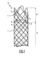
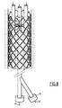
- the tubular prosthesis 10 shown on the figure 1 is intended to be placed in a blood vessel. It comprises a tubular body 11 comprising a lattice 12 embedded, for most of the length of the prosthesis, in a film 14 of the body 11.
- the prosthesis further comprises, in the vicinity of one of its ends, three clamps 16 regularly distributed angularly at its periphery.
- Each clamp 16 is formed of two hooks 18, 19 carried by the wire mesh 12. These hooks 18, 19 are movable relative to each other between a spaced position in which the clamp is open and a close position in which the clamp is closed.
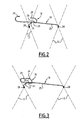
- the clamp further comprises a guide member 20 carried by one of the hooks 18, 19 (see Figures 2 and 3 ).
- the hook 18, 19 carrying the member 20 is a guide hook 18 delimiting a guide passage 21 in which is engaged the other hooks 18, 19, which is a hook 19 guided.
- the clamps 16 are provided on an end section 22 of the film-free prosthesis 14, the mesh 12 thus not being covered in this region.
- the mesh 12 is embedded in the film 14.
- the clamps 16 are provided on the entire section of the prosthesis, especially when the latter is devoid of film.
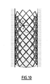
- the mesh 12 is made of stainless steel of biocompatible quality. It is made for example by braiding or knitting a yarn, axial deployment of a tube, or by any other appropriate technique.
- the mesh 12 consists of two bundles of son helically wound in opposite directions, the son of the same beam extending generally parallel to each other and transversely to the son of the bundle of son wound in the opposite direction.
- the wires of the two bundles of opposite windings intersect alternately above and below.
- the mesh 12 is preferably elastically deformable by radial expansion, between a retracted state of small diameter and a dilated state of larger diameter.
- the meshes of the lattice form lozenges generally elongated in the circumferential direction.
- the meshes form elongated lozenges parallel to the axis of the prosthesis.
- the prosthesis is plastically deformable, that is to say that the body 11 and the mesh 12 have a first stable shape of small diameter and a second stable shape of enlarged diameter.
- the mesh 12 is entirely embedded in the film 14.
- This film is formed of an extensible and liquid-tight material which fills the mesh.
- Suitable materials are a biocompatible elastomer which may be a natural or synthetic rubber or a biocompatible polymer such as polyurethane.
- the coating of the mesh 12 by the film 14 is obtained for example by a technique of coextrusion or dipping, after degreasing of the metal and its treatment with a primary substance of adhesion.
- each hook 18, 19 is formed of a filiform metal element whose free end is bent outwards to form a butt 24.
- the hooks 18, 19 overlap to form the clamp 16 between the butts 24 facing.
- the butts 24 are analogous.
- Each hook 18, 19 comprises an arm 25 extended by the butt 24.
- the arm 25 of the guided hook 19 constitutes a rectilinear section.
- the arm 25 of the guide hook 18 comprises a loop constituting the guide member 20.
- the loop is made by a twist of the hook 18 on itself on a turn or any other number of turns adapted.
- the twist is performed around the guided hook 19, which facilitates the assembly of the clamps 16.
- the twist is made by plastic deformation, so that it is permanent.
- the guide member 20 formed by the twist is located in the vicinity of the butt 24 of the guide hook 18, in the extension of the butt 24
- the guided hook 19 is movable along an axis of translation and two orthogonal axes of rotation in the passage 21 delimited by the member 20. The mechanical stresses that can be exerted between the two hooks 18, 19 are thus minimized.
- the guide member 20 is formed by twisting the hook 18 on itself on more than one turn.
- the passage 21 is not delimited by a loop. It is for example delimited by a ring, or a tube or by any other element of appropriate shape to guide the hook 19.
- each arm 25 is fixed to the wire mesh 12 in the opposite corners of a mesh visible on the Figures 2 and 3 .
- the butts 24 protrude outwards with respect to the tubular section delimited by the body 11 and the mesh 12, and their curved ends extend, at rest, in a plane transverse to the tubular prosthesis, that is to say say perpendicular to its general axis.
- the diameter of the hooks 24 of the hooks 18, 19 is between 0.1 and several millimeters.
- the diameter of the butts 24 is smaller than the diameter of the passage 21.
- the length of the arm 25 of the guided hook 19 is adapted to the diameter of the prosthesis 10.
- the length of the arm 25 of the guide hook 18 is small and less than that of the arm 25 of the guided hook 19 so that the member 20 is very close to the anchoring point 28 of the hook 18.
- the short length of the arm 25 of the guide hook 18 ensures the rigidity of the arm 25 and thus increases the reliability of the guide.
- the diameter of the passage 21 is greater than the diameter of the section of the arm 25 of the hook 19.
- the lengths of the arms 25 are such that, in the dilated state of the prosthesis illustrated in FIG. figure 1 the two hooks 24 of the hooks 18, 19 are brought together and together define a closed or substantially closed loop.
- the prosthesis is associated with means 30 for releasably retaining the clamps 16 in their open position.
- the prosthesis 10 whose clips 16 are kept open is received, as known per se, in a drop tube 32 within which the prosthesis is confined in its retracted state.
- the inner pipe of the tube 32 has longitudinally channels 33 for receiving the ends of the hooks 18, 19 protruding from the generally tubular surface of the wire mesh.
- each holding means of an open clamp 16 comprises a flexible tube 34 formed for example of PEEK.
- This tube 34 extends longitudinally between a distal end 36 intended to be received in the blood vessel and a proximal end 38 intended to be accessible by the surgeon from the body of the patient.
- the tube 34 has for example a length of one meter.
- a retaining opening 40 is formed laterally in the tube 34 generally facing the associated clamp 16.
- the tube 34 is also equipped, in the vicinity of its proximal end 38, with a hollow lateral branch 42 equipped with a ring 43 for axially locking a sliding wire.
- the releasable retaining means 30 further comprise a retaining rod 44 engaged axially in the tube 34, and a retaining wire 46 surrounding the mesh of the prosthesis carrying the clip 16.
- the retaining rod 44 extends from one end to the other of the tube 34. It projects out of the tube at the proximal end 38.
- This rod is movable in the tube 34 between a retaining position in which the rod is opposite the opening 40 and a release position in which the rod 44 is away from the opening 40 and is shifted towards the proximal end of the tube 34.
- the retaining wire 46 comprises a single strand which comprises at one end a loop 48, a clamping loop 50 and a control section 52 which extends along the entire length of the tube 34 of the opening 40 to the branch 42 out of which it protrudes after having passed through the locking ring 43.
- the end loop 48 is formed of a closed loop of small diameter in which is initially engaged the rod 44 when the latter is in its retaining position.
- the clamping loop 50 is formed by a section of the strand, slidably engaged through two meshes of the mesh adjacent to the mesh carrying the clamp 16.
- the clamping loop passes through the opening 40 to join the loop 48 at one end and the control section 52 at its other end.
- the active length of the clamping loop 50 is variable depending on the traction exerted on the control section 52, so that it controls the shape of the mesh carrying the clamp 16, as will be discussed below.
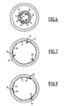
- the prosthesis is disposed in the delivery tube 32 and the control sections 52 of the clamp retaining means are tensioned, so that the clamps are held open, as shown in FIGS. figures 5 and 6 .
- the clamping loop 50 tightens the mesh carrying the clamp, so that the diamond defining the mesh is elongated along its diagonal parallel to the axis of the prosthesis.
- the prosthesis For the placement of the prosthesis, it is introduced with the tube 32 to the drop zone and the tube 32 is removed thus releasing the prosthesis. This expands and is then pressed against the inner surface of the blood vessel, as shown on the figures 7 and 8 .
- the meshes of the lattice of the prosthesis extend thanks to the elasticity of the lattice along the diagonal periphery of the prosthesis thus allowing an increase in the diameter of the prosthesis.
- the meshes carrying a pincer remain contracted, as illustrated on the figure 8 because of the clamping loop 50.
- the clamps 16 are accosted against the surface of the blood vessel while they are still in the open position.
- the practitioner By acting on the locking ring 43, the practitioner then proceeds to release the retaining son to allow the elastic deformation of the mesh carrying the clamps 16, and thus the approximation of the two opposite hooks 18, 19, causing the closure of the clip 16 and the penetration of the hooks 18, 19 in the wall delimiting the blood vessel, as illustrated in FIGS. figures 9 and 10 .
- the guided hook 19 slides in the guiding member 20.
- the guiding member 20 being situated in the vicinity of the butt 24 of the guide hook 18, the butt 24 of the guided hook 19 is necessarily close to that of the guide hook 18 when closing the clamp 16. This closure is reliable regardless of the deformation of the mesh 12.
- the relative position of the butts 24 of the two hooks 18, 19 is substantially the same as during a uniform deformation of the mesh. Indeed, in close position, the butts 24 are maintained in the vicinity of each other by the guide member 20 and the clip function of the hooks 18, 19 is preserved.
- the rod 44 After loosening of the retaining wire 46, the rod 44 is brought into the release position, so that the loop 48 is released from the rod 44. The practitioner then pulls on the control section 52 allowing the retaining wire 46 s' escapes from the wire mesh, circulating through the two meshes adjacent to the mesh carrying the clamp.
- the retaining means of the clamp being rendered independent of the prosthesis, they can be extracted endoluminally.
- the guide of the hook 19 by the hook 18 stiffens the clamp 16 formed by the two hooks 18, 19. If one of the hooks 18, 19 is subjected to an external stress, it is retained by the other hook 18 , 19 through the member 20 to remain in the vicinity of one another. If the hooks 18, 19 are deformed around their attachment point 28, their relative position remains substantially unchanged and the function of the clamp 16 preserved.
- the hook 19 is movable in the hook 18 along two orthogonal axes of rotation and at least one translation axis. The stresses exerted on the hooks 18, 19 between them are thus minimized.
- the guide member is carried by the lattice.
- the two hooks are then engaged in the guide member.
- the guide member is for example constituted by a rigid rod welded to the mesh carrying the clamp, the rod being extended by a ring forming the guide member.
- the guide member 20 is of any known type suitable, such as for example a ring secured to the hook 18.
- FIG. 11 On the figure 11 is shown a second embodiment of a prosthesis according to the invention.
- each strand of wire that forms the node extends in two directions parallel to one another and close to each other.
- the wire F1 starts from a twist 112 and then successively forms a node 115, a node 117, a node 115, another node 115, a node 117, a node 115, another node 115, a loop 104, a node 115, another node 115, a node 117, a node 115, another node 115, a node 117, a node 115 and another twist 112.
- each gripper denoted 116 is formed of a single wire 120 whose current portion is engaged and twisted around the wires defining the trellis, and whose two free ends are bent outwards to form hooks. 118, 119 similar to the hooks 18, 19 of the previous embodiment.
- the guide hook 118 also comprises a guide member 20 delimiting a guide passage 21 in which the guided hook 119 is engaged.
- the wire 120 is twisted from a node 115 around two diverging angularly offset strands. Each branch of the wire 120 is then twisted with the next twisted knot and then extends transversely along a diameter of the mesh, to form the two arms 25 and the two hooks 24 of the hooks 118, 119.
- the deformation of the mesh carrying the clamp 116 causes the opening or closing of the clamp 116, the two hooks 118, 119 with curved end moving relative to one another. other.
- the guide member 20 similarly ensures the reliability of the fixing by holding the hooks 118, 119 facing one another after deployment of the prosthesis 100.
- the body 11 of the vascular prosthesis 200 is formed by a fabric tube 212 deployable between a retracted state and an expanded state of large diameter. This is, for example a fabric dacron.
- Two hooks 218, 219 similar to the hooks 118, 119 of the second embodiment are sewn onto the tube 212.
- the hooks 218, 219 are formed by a single wire 220 in the shape of a triangle, the hooks 218, 219 and the guide 20 being placed in the vicinity of a vertex of the triangle.
- the deployment of the fabric 212 to its expanded state moves the two hooks 218, 219 between their spaced apart position and their close position, this displacement being guided by the guide member 20.
- the tissue 212 is not deployable spontaneously to its expanded state.
- the tissue prosthesis 200 is maintained in its retracted state.
- the clamp 216 is open and the hooks 218, 219 are disposed apart from each other.
- the surface delimited by the wire 220 in the form of a triangle is then minimal.
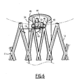
- the prosthesis 200 is deployed by means of an inflatable balloon 230 between a retracted state and an expanded state, inserted into the tissue tube 212.
- the balloon 230 is brought into the tube 212 by the delivery tube 32 into the tube 212. its state retracted then is inflated.
- Deployment of the fabric tube 212 causes the surface demarcated by the wire 220 to increase.
- the guided hook 219 then approaches the guide hook 218 while being kept close to it by the guide member 20.
- the clips 216 ensure, by their radial attachment in the blood vessel, the maintenance of the tissue 212 in its expanded state.
- the two hooks 218, 219 provide, as in the two previous embodiments, the axial attachment of the prosthesis 200.
- the release device does not have retaining means 30 of the clamp in its open position.
- the closing of the clamp 216 takes place as the fabric 212 is deployed.
- the body 11 of the prosthesis 300 is similar to that of the third embodiment.
- the prosthesis 300 further comprises a deformable ring 302 surrounding the 212 and sewn with the latter by means of a wire 303.
- the ring 302 is thus provided to deform with the tissue 212 between a retracted state in which it has a minimum diameter and an expanded state in which it has a diameter. maximum.
- the ring 302 carries, at its ends, the two hooks 318, 319, and the guide member 20 and moves them between their spaced apart position and their close position during its deformation.
- the two hooks 318, 319 are for example similar to the hooks of the first embodiment and have their ends 28 welded to the ring 302.
- the ring 302 is used with the prostheses 10, 100 of the first and second embodiments.
Claims (13)
- Röhrenförmige Prothese (10, 100, 200, 300), die radial verformbar ist, des Typs der einen röhrenförmigen Körper (11) aufweist, der zwischen einem Zusammenziehungszustand mit verringertem Durchmesser und einem Dehnungszustand mit einem größeren Durchmesser verformbar ist, wobei die Prothese (10, 100, 200, 300) mindestens zwei äußere Haken (18, 19, 118, 119, 218, 219, 318, 319) aufweist, die zwischen einander eine Klemme (16, 116, 216, 316) zum Einhaken in ein äußeres Gewebe begrenzen, wobei die beiden Haken (18, 19, 118, 119, 218, 219, 318, 319) von dem Körper (11) getragen werden und zwischen einer Spreizposition, in der die Klemme (16, 116, 216, 316) geöffnet ist und einer Annäherungsposition, in der die Klemme (16, 116, 216, 316) geschlossen ist, bewegbar sind, dadurch gekennzeichnet, dass die Prothese (10, 100, 200, 300) ein Mittel (20) zum Führen der Bewegung von mindestens einem der Haken (18, 19, 118, 119, 218, 219, 318, 319) bei der Verformung der Prothese (10, 100, 200, 300) aufweist, wobei das Führungsmittel (20) einen Führungsdurchgang (21) begrenzt, in welchen mindestens einer der Haken (18, 19, 118, 119, 218, 219, 318, 319) eingreift.
- Prothese (10, 100, 200, 300) gemäß Anspruch 1, dadurch gekennzeichnet, dass die Haken (18, 19, 118, 119, 218, 219, 318, 319) einen Führungshaken (18, 118, 218, 318) und einen geführten Haken (19, 119, 219, 319) aufweisen, wobei das Führungsmittel (20) an dem Führungshaken (18, 118, 218, 318) ausgebildet ist, wobei der Führungsdurchgang (21) den geführten Haken (19, 119, 219, 319) aufnimmt.
- Prothese (10, 100, 200, 300) gemäß Anspruch 1 oder 2, dadurch gekennzeichnet, dass die Haken (18, 19, 118, 119, 218, 219, 318, 319) einen geführten Haken (19, 119, 219, 319) aufweisen, wobei der Führungsdurchgang (21) den geführten Haken (19, 119, 219, 319) aufnimmt, und dadurch, dass beim Annähern der beiden Haken (18, 19, 118, 119, 218, 219, 318, 319) der geführte Haken (19, 119, 219, 319) in dem Führungsmittel (20) gleitet.
- Prothese (10, 100, 200, 300) gemäß einem der vorhergehenden Ansprüche, dadurch gekennzeichnet, dass das Führungsmittel (20) durch eine Verdrillung des Führungshakens (18, 118, 218, 318) mit sich selbst gebildet wird.
- Prothese (10, 100, 200, 300) gemäß Anspruch 4, dadurch gekennzeichnet, dass die Verdrillung über mindestens eine Umdrehung realisiert ist.
- Prothese (10, 100, 200, 300) gemäß einem der vorhergehenden Ansprüche, dadurch gekennzeichnet, dass jeder Haken (18, 19, 118, 119, 218, 219, 318, 319) von einem Verbindungsende aus mit dem Körper (11) verbunden ist, und die Haken (18, 19, 118, 119, 218, 219, 318, 319) einer selben Klemme (16, 116, 216, 316) bei der Verformung der Prothese (10, 100, 200, 300) relativ zueinander bewegbar sind.
- Prothese (300) gemäß einem der vorhergehenden Ansprüche, dadurch gekennzeichnet, dass der Körper 811) einen elastischen Ring (302) aufweist, der den Körper (11) umfasst, wobei der Ring (302) mit dem Körper (11) verbunden ist und sich mit dem Körper (11) zwischen einem Zusammenziehungszustand und einem Dehnungszustand verformt, wobei der Ring (302) die beiden Haken (318, 319) trägt und sie bei seiner Verformung zwischen ihrer Spreizposition und ihrer Annäherungsposition bewegt.
- Prothese (10, 100) gemäß einem der vorhergehenden Ansprüche, dadurch gekennzeichnet, dass der Körper (11) ein Gitter (12) aufweist, das zwischen dem Zusammenziehungszustand und dem Dehnungszustand verformbar ist und Fäden aufweist, die miteinander verflochten sind, um eine Vernetzung von verformbaren Vierecken zu bilden, und dass jeder Haken (18, 19, 118, 119) in einer Ecke des Vierecks mit dem Gitter (12) verbunden ist.
- Prothese (10) gemäß Anspruch 8, dadurch gekennzeichnet, dass jeder Haken (18, 19) an seinem Verbindungsende an dem Gitter (12) befestigt ist.
- Prothese (10, 100) gemäß Anspruch 8, dadurch gekennzeichnet, dass jeder Haken (118, 119) an seinem Verbindungsende durch eine verdrillte Faser (120) um das Gitter (12) herum verlängert ist.
- Prothese (200) gemäß einem der Ansprüche 1 bis 7, dadurch gekennzeichnet, dass der röhrenförmige Körper (11) ein Gewebe (212) aufweist, das zwischen dem Zusammenziehungszustand und dem Dehnungszustand verformbar ist, wobei die beiden Haken (218, 219) derart an dem Gewebe befestigt sind, dass sie das Ausdehnen des Gewebes (212) zwischen ihrer Spreizposition und ihrer Annäherungsposition bewegt.
- Satz zur Behandlung eines Blutgefäßes, dadurch gekennzeichnet, dass er aufweist:- eine Prothese (10, 100, 300) gemäß einem der Ansprüche 1 bis 11,- Mittel (30) zum Halten des zusammengezogenen Körpers (11) in dem Bereich der oder jeder Klemme (16),- ein Rohr (32) zum Erweitern des Körpers (11), das eine Röhre zum Umschließen der Prothese (10) in ihrem Zusammenziehungszustand begrenzt.
- Satz gemäß Anspruch 12, dadurch gekennzeichnet, dass die Umschließungsröhre des Erweiterungsrohrs (32) längsverlaufende Kanäle (33) zum Aufnehmen der Haken (18, 19, 118, 119, 318, 319) aufweist.
Applications Claiming Priority (1)
| Application Number | Priority Date | Filing Date | Title |
|---|---|---|---|
| FR0755892A FR2917603B1 (fr) | 2007-06-20 | 2007-06-20 | Prothese tubulaire et necessaire associe |
Publications (2)
| Publication Number | Publication Date |
|---|---|
| EP2005918A1 EP2005918A1 (de) | 2008-12-24 |
| EP2005918B1 true EP2005918B1 (de) | 2009-12-16 |
Family
ID=38926106
Family Applications (1)
| Application Number | Title | Priority Date | Filing Date |
|---|---|---|---|
| EP08104456A Active EP2005918B1 (de) | 2007-06-20 | 2008-06-18 | Röhrenförmige Prothese und entsprechendes Zubehör |
Country Status (7)
| Country | Link |
|---|---|
| US (1) | US8623072B2 (de) |
| EP (1) | EP2005918B1 (de) |
| JP (1) | JP2009000523A (de) |
| CN (1) | CN101327152B (de) |
| BR (1) | BRPI0802341A2 (de) |
| DE (1) | DE602008000402D1 (de) |
| FR (1) | FR2917603B1 (de) |
Families Citing this family (7)
| Publication number | Priority date | Publication date | Assignee | Title |
|---|---|---|---|---|
| GB2469297B (en) * | 2009-04-07 | 2011-05-25 | Cook Inc | Introducer assembly and implantable medical device |
| US20130289690A1 (en) | 2011-11-01 | 2013-10-31 | Hira V. Thapliyal | Personalized prosthesis and methods of use |
| JP6729552B2 (ja) * | 2015-03-12 | 2020-07-22 | 株式会社ジェイ・エム・エス | 合成樹脂ステント |
| CN104720936B (zh) * | 2015-03-26 | 2017-07-07 | 杭州启明医疗器械有限公司 | 使用安全的瓣膜支架以及具有该瓣膜支架的瓣膜置换装置 |
| US10709543B2 (en) | 2017-07-19 | 2020-07-14 | Cook Medical Technologies Llc | Non-cylindrical mesh top stent with twisted sections |
| US10709544B2 (en) | 2017-07-19 | 2020-07-14 | Cook Medical Technologies Llc | Non-cylindrical variable pitch mesh top stent |
| US11925570B2 (en) | 2018-12-19 | 2024-03-12 | Boston Scientific Scimed, Inc. | Stent including anti-migration capabilities |
Family Cites Families (5)
| Publication number | Priority date | Publication date | Assignee | Title |
|---|---|---|---|---|
| US6074416A (en) * | 1997-10-09 | 2000-06-13 | St. Jude Medical Cardiovascular Group, Inc. | Wire connector structures for tubular grafts |
| AU2003299404A1 (en) * | 2003-12-23 | 2005-08-11 | Laboratoires Perouse | Kit which is intended to be implanted in a conduit |
| FR2865926B1 (fr) * | 2004-02-11 | 2006-05-12 | Perouse Laboratoires | Prothese tubulaire. |
| US7491211B2 (en) * | 2004-05-25 | 2009-02-17 | Boston Scientific Scimed, Inc. | Medical retrieval devices |
| US8142488B2 (en) * | 2004-10-25 | 2012-03-27 | Merit Medical Systems, Inc. | Stent removal and repositioning aid and associated method |
-
2007
- 2007-06-20 FR FR0755892A patent/FR2917603B1/fr not_active Expired - Fee Related
-
2008
- 2008-06-18 EP EP08104456A patent/EP2005918B1/de active Active
- 2008-06-18 DE DE602008000402T patent/DE602008000402D1/de active Active
- 2008-06-19 JP JP2008160129A patent/JP2009000523A/ja active Pending
- 2008-06-20 BR BRPI0802341-7A patent/BRPI0802341A2/pt not_active IP Right Cessation
- 2008-06-20 US US12/213,545 patent/US8623072B2/en active Active
- 2008-06-20 CN CN200810144655.0A patent/CN101327152B/zh active Active
Also Published As
| Publication number | Publication date |
|---|---|
| FR2917603A1 (fr) | 2008-12-26 |
| BRPI0802341A2 (pt) | 2009-05-12 |
| US20080319552A1 (en) | 2008-12-25 |
| CN101327152A (zh) | 2008-12-24 |
| FR2917603B1 (fr) | 2010-09-10 |
| US8623072B2 (en) | 2014-01-07 |
| CN101327152B (zh) | 2013-07-31 |
| EP2005918A1 (de) | 2008-12-24 |
| DE602008000402D1 (de) | 2010-01-28 |
| JP2009000523A (ja) | 2009-01-08 |
Similar Documents
| Publication | Publication Date | Title |
|---|---|---|
| EP1713414B1 (de) | Röhrenförmige prothese | |
| EP2005918B1 (de) | Röhrenförmige Prothese und entsprechendes Zubehör | |
| EP1842508B1 (de) | Vorrichtung zur Behandlung eines Blutschlauchs und Verfahren zur Herstellung dieser Vorrichtung | |
| EP1976454B1 (de) | Vorrichtung zur behandlung einer blutführenden leitung und zugehöriges herstellungsverfahren | |
| EP1909695B1 (de) | Vorrichtung zur behandlung eines blutgefässes | |
| EP0878175B1 (de) | System zum Ausbessern eines Körpergefässes durch ein Implantat mit einer sich stufenweise ausweiterbaren Öffnung | |
| FR2932080A1 (fr) | Dispositif de traitement d'un conduit de circulation du sang | |
| EP2266503B1 (de) | Verfahren zur herstellung für eine herzklappenprothese | |
| EP0843538B1 (de) | Interne ausdehnbare manschette zum chirurgischen gebrauch zur dehnung physiologischer gefässe | |
| EP2000116B1 (de) | Kit zum Implantieren in eine Blutkreislaufbahn | |
| FR2894131A1 (fr) | Dispositif de traitement d'un vaisseau sanguin, et necessaire de traitement associe. | |
| CA2424319C (fr) | Dispositif d'occlusion vasculaire, appareil et procede d'utilisation | |
| FR2714816A1 (fr) | Prothèse vasculaire implantable dans un organisme vivant pour le traitement des anévrismes. | |
| EP2363096A1 (de) | Band zur Wiederherstellung des Ansatzes an einen Knochen eines Bindegewebes, wie eine Sehne oder ein Band | |
| FR2913879A1 (fr) | Dispositif de largage d'un implant expansible radialement, necessaire de traitement et procede de largage associe | |
| FR2694687A1 (fr) | Prothèse vasculaire pour filtrer le sang dans un vaisseau et dispositif d'intervention pour un tel filtrage temporaire. | |
| FR2863160A1 (fr) | Dispositif de traitement d'un vaisseau sanguin et procede de preparation de ce dispositif | |
| FR2779939A1 (fr) | Dispositif de traitement d'un vaisseau sanguin | |
| FR2946865A1 (fr) | Dispositif de traitement d'un conduit de circulation du sang | |
| FR2833153A1 (fr) | Endoprothese tubulaire a manche tissee et armature de support | |
| FR2779938A1 (fr) | Necessaire de traitement d'un vaisseau sanguin | |
| FR3108029A1 (fr) | Dispositif de traitement d’un vaisseau sanguin | |
| WO2021064303A1 (fr) | Dispositif de pose et de fixation d'un implant de renfort sur une valve mitrale d'un cœur, avec des sutures a memoire de forme et par voie transfemorale | |
| FR2712797A1 (fr) | Système d'occlusion vasculaire. | |
| FR2947717A1 (fr) | Dispositif de traitement d'un conduit sanguin |
Legal Events
| Date | Code | Title | Description |
|---|---|---|---|
| PUAI | Public reference made under article 153(3) epc to a published international application that has entered the european phase |
Free format text: ORIGINAL CODE: 0009012 |
|
| AK | Designated contracting states |
Kind code of ref document: A1 Designated state(s): AT BE BG CH CY CZ DE DK EE ES FI FR GB GR HR HU IE IS IT LI LT LU LV MC MT NL NO PL PT RO SE SI SK TR |
|
| AX | Request for extension of the european patent |
Extension state: AL BA MK RS |
|
| 17P | Request for examination filed |
Effective date: 20090527 |
|
| GRAP | Despatch of communication of intention to grant a patent |
Free format text: ORIGINAL CODE: EPIDOSNIGR1 |
|
| AKX | Designation fees paid |
Designated state(s): DE FR |
|
| GRAS | Grant fee paid |
Free format text: ORIGINAL CODE: EPIDOSNIGR3 |
|
| GRAA | (expected) grant |
Free format text: ORIGINAL CODE: 0009210 |
|
| AK | Designated contracting states |
Kind code of ref document: B1 Designated state(s): DE FR |
|
| REF | Corresponds to: |
Ref document number: 602008000402 Country of ref document: DE Date of ref document: 20100128 Kind code of ref document: P |
|
| PLBE | No opposition filed within time limit |
Free format text: ORIGINAL CODE: 0009261 |
|
| STAA | Information on the status of an ep patent application or granted ep patent |
Free format text: STATUS: NO OPPOSITION FILED WITHIN TIME LIMIT |
|
| 26N | No opposition filed |
Effective date: 20100917 |
|
| REG | Reference to a national code |
Ref country code: FR Ref legal event code: PLFP Year of fee payment: 8 |
|
| REG | Reference to a national code |
Ref country code: DE Ref legal event code: R082 Ref document number: 602008000402 Country of ref document: DE Representative=s name: VIERING, JENTSCHURA & PARTNER MBB PATENT- UND , DE Ref country code: DE Ref legal event code: R081 Ref document number: 602008000402 Country of ref document: DE Owner name: CORMOVE, FR Free format text: FORMER OWNER: LABORATOIRES PEROUSE, IVRY LE TEMPLE, FR |
|
| REG | Reference to a national code |
Ref country code: FR Ref legal event code: TP Owner name: CORMOVE, FR Effective date: 20151215 |
|
| REG | Reference to a national code |
Ref country code: FR Ref legal event code: TP Owner name: CORMOVE, FR Effective date: 20151228 |
|
| REG | Reference to a national code |
Ref country code: FR Ref legal event code: PLFP Year of fee payment: 9 |
|
| REG | Reference to a national code |
Ref country code: FR Ref legal event code: PLFP Year of fee payment: 10 |
|
| REG | Reference to a national code |
Ref country code: FR Ref legal event code: PLFP Year of fee payment: 11 |
|
| PGFP | Annual fee paid to national office [announced via postgrant information from national office to epo] |
Ref country code: FR Payment date: 20220512 Year of fee payment: 15 Ref country code: DE Payment date: 20220607 Year of fee payment: 15 |
|
| REG | Reference to a national code |
Ref country code: DE Ref legal event code: R119 Ref document number: 602008000402 Country of ref document: DE |