EP2005449B1 - Elektromagnetisches betätigungsglied - Google Patents
Elektromagnetisches betätigungsglied Download PDFInfo
- Publication number
- EP2005449B1 EP2005449B1 EP07732324.4A EP07732324A EP2005449B1 EP 2005449 B1 EP2005449 B1 EP 2005449B1 EP 07732324 A EP07732324 A EP 07732324A EP 2005449 B1 EP2005449 B1 EP 2005449B1
- Authority
- EP
- European Patent Office
- Prior art keywords
- solenoid
- coil
- gap
- actuator
- actuator according
- Prior art date
- Legal status (The legal status is an assumption and is not a legal conclusion. Google has not performed a legal analysis and makes no representation as to the accuracy of the status listed.)
- Not-in-force
Links
Images


Classifications
-
- H—ELECTRICITY
- H01—ELECTRIC ELEMENTS
- H01F—MAGNETS; INDUCTANCES; TRANSFORMERS; SELECTION OF MATERIALS FOR THEIR MAGNETIC PROPERTIES
- H01F7/00—Magnets
- H01F7/06—Electromagnets; Actuators including electromagnets
- H01F7/08—Electromagnets; Actuators including electromagnets with armatures
- H01F7/16—Rectilinearly-movable armatures
- H01F7/1638—Armatures not entering the winding
- H01F7/1646—Armatures or stationary parts of magnetic circuit having permanent magnet
-
- F—MECHANICAL ENGINEERING; LIGHTING; HEATING; WEAPONS; BLASTING
- F02—COMBUSTION ENGINES; HOT-GAS OR COMBUSTION-PRODUCT ENGINE PLANTS
- F02M—SUPPLYING COMBUSTION ENGINES IN GENERAL WITH COMBUSTIBLE MIXTURES OR CONSTITUENTS THEREOF
- F02M51/00—Fuel-injection apparatus characterised by being operated electrically
- F02M51/06—Injectors peculiar thereto with means directly operating the valve needle
- F02M51/061—Injectors peculiar thereto with means directly operating the valve needle using electromagnetic operating means
- F02M51/0625—Injectors peculiar thereto with means directly operating the valve needle using electromagnetic operating means characterised by arrangement of mobile armatures
- F02M51/0635—Injectors peculiar thereto with means directly operating the valve needle using electromagnetic operating means characterised by arrangement of mobile armatures having a plate-shaped or undulated armature not entering the winding
-
- H—ELECTRICITY
- H01—ELECTRIC ELEMENTS
- H01F—MAGNETS; INDUCTANCES; TRANSFORMERS; SELECTION OF MATERIALS FOR THEIR MAGNETIC PROPERTIES
- H01F7/00—Magnets
- H01F7/06—Electromagnets; Actuators including electromagnets
- H01F7/08—Electromagnets; Actuators including electromagnets with armatures
- H01F7/16—Rectilinearly-movable armatures
- H01F2007/1692—Electromagnets or actuators with two coils
-
- H—ELECTRICITY
- H01—ELECTRIC ELEMENTS
- H01F—MAGNETS; INDUCTANCES; TRANSFORMERS; SELECTION OF MATERIALS FOR THEIR MAGNETIC PROPERTIES
- H01F7/00—Magnets
- H01F7/06—Electromagnets; Actuators including electromagnets
- H01F7/08—Electromagnets; Actuators including electromagnets with armatures
- H01F7/18—Circuit arrangements for obtaining desired operating characteristics, e.g. for slow operation, for sequential energisation of windings, for high-speed energisation of windings
- H01F2007/1888—Circuit arrangements for obtaining desired operating characteristics, e.g. for slow operation, for sequential energisation of windings, for high-speed energisation of windings using pulse width modulation
-
- H—ELECTRICITY
- H01—ELECTRIC ELEMENTS
- H01F—MAGNETS; INDUCTANCES; TRANSFORMERS; SELECTION OF MATERIALS FOR THEIR MAGNETIC PROPERTIES
- H01F7/00—Magnets
- H01F7/06—Electromagnets; Actuators including electromagnets
- H01F7/08—Electromagnets; Actuators including electromagnets with armatures
- H01F7/081—Magnetic constructions
-
- H—ELECTRICITY
- H01—ELECTRIC ELEMENTS
- H01F—MAGNETS; INDUCTANCES; TRANSFORMERS; SELECTION OF MATERIALS FOR THEIR MAGNETIC PROPERTIES
- H01F7/00—Magnets
- H01F7/06—Electromagnets; Actuators including electromagnets
- H01F7/08—Electromagnets; Actuators including electromagnets with armatures
- H01F7/18—Circuit arrangements for obtaining desired operating characteristics, e.g. for slow operation, for sequential energisation of windings, for high-speed energisation of windings
- H01F7/1844—Monitoring or fail-safe circuits
Definitions
- This invention relates to a solenoid actuator useful for application to hydraulic valves and to a valve arrangement incorporating such an actuator.
- Fluid power systems often rely upon solenoid-actuated valves to control the flow of fluid. It is often advantageous to be able to switch fluid from one path to another as fast as possible, such that the time spent in intermediate positions is minimised, hence minimising energy losses caused by pressure drops though the valve.
- valves are constructed as single acting solenoids, whereby a ferromagnetic sliding member such as a spool or a poppet is attracted to an end face of a solenoid, the return flux being passed into the ferromagnetic member in a direction transverse to the axis of the solenoid, such that flux flowing in the circuit produces a net axial force on the moving member which moves it from one position to another.
- a solenoid cannot produce a force acting in the opposite sense so this force is provided by a spring or some component of the fluid pressure.
- Such valves often have transit times in the direction of actuation of the order of 40 ms.
- Hydraulic/pneumatic pumps and motors are referred to herein as "fluid-working machines”.
- a new class of such machines is emerging in which the commutation of the working chambers is provided not by mechanical means such as port plates, but by solenoid-actuated valves controlled by a digital computer.
- This technique allows such a machine to displace fluid in discrete units, and the applicant's machines are therefore termed “Digital Displacement (TM)”.
- TM Digital Displacement
- Operators of these pumps wish to drive them directly from the shafts of industrial diesel engines, which run in the range 1800 - 2800 rpm. In order to achieve these speeds the commutating valves must actuate many times each second. Actuation time should be kept below 5 ms for accurate commutation.
- Solenoid valves according to the prior art cannot achieve this speed of actuation.
- a restoring force to keep the armature in the original position which is the default position if the coil is inactive.
- the coil Before the armature moves, the coil must be charged with current, which, because of the high inductance of the coil, takes many milliseconds - this is termed the latency of the coil.
- Force builds on the armature gradually, until it exceeds this restoring force and causes acceleration of the armature towards the second position. The initial acceleration is low as the force builds gradually, due to the long time constant of the coil.
- EP 1 788 591 discloses an electromagnetic actuator according to the preamble of claim 1.
- the present invention solves the aforementioned problems and allows a solenoid valve that is fast enough for accurate commutation of a reciprocating fluid volume at the speed of a diesel engine.
- a solenoid valve that is fast enough for accurate commutation of a reciprocating fluid volume at the speed of a diesel engine.
- it has wider application wherever valves need to be actuated quickly, or indeed as a fast direct solenoid actuator outside of the domain of fluid valves.
- the invention provides an electromagnetic actuator according to claim 1.
- the actuator comprises a core, a ferromagnetic component ("the armature”) movable in a gap in said core, a magnet for attracting said component to one side of said gap ("the latch gap”), a flux concentrator for concentrating the magnetic flux on said one side of the gap, a solenoid for producing magnetic flux in said gap, a magnetic circuit of said solenoid being defined by part of said core, part of said gap and by a further gap (“the radial gap”) between the ferromagnetic component and the core, and a demagnetiser having a magnetic circuit defined by another part of said core, another part of said gap and by said further gap, the demagnetiser being arranged to demagnetise the magnet at least to the extent that the magnetic flux produced by the solenoid is diverted from said flux concentrator into said further gap and said movable component is movable away from the magnet under the magnetic force of the solenoid.
- the demagnetiser comprises a coil having a lower latency than the latency of the solenoid.
- the actuator may include an electronic driver circuit arranged to provide voltage pulses to the solenoid and the coil such that each of the solenoid and the coil produce magnetic flux in the same direction in an overlapping part of each magnetic circuit.
- a digital controller may be arranged to send signals to the drive circuit such that the solenoid is energised in advance of a time at which the actuator is desired to act, and the coil is energised after the solenoid.
- the digital controller may be arranged to send a signal to the drive circuit such that the solenoid is energised in advance of a time at which the actuator may be desired to act, the coil then being energised only in response to a decision to actuate the actuator.
- the flux concentrator may comprise a taper of the magnet or of an adjacent ferromagnetic element in a direction towards the solenoid.
- the actuator may be functionally symmetrical about an axis.
- the actuator may be functionally symmetrical about a plane and comprise at least two cores and two magnets, one of each side of the plane.
- the invention further provides a valve arrangement for a fluid-working machine, comprising a valve member attached to the movable ferromagnetic component of the actuator defined above.
- the invention provides a fluid-working machine including such a valve arrangement, fluid flow into or from or both into and from one or more working chamber(s) of the machine being controlled to some degree by the valve actuation.
- the digital controller may be synchronized to a rotating shaft of the machine.
- the actuator of Figure 1 is symmetrical about an axis A and comprises a core 1 of steel or other ferromagnetic material and which may be formed from a plurality of components.
- a moving ferromagnetic component (“armature") 2 is attached via a sliding non-magnetic body 3 to the valve spool or poppet or other element to be actuated.
- a first magnetic circuit incorporates part of the core 1, a permanent magnet 4, an "axial" air gap 5 ("latch gap”, shown in Figure 2 ), a “radial” air gap 6, and a first coil ("trigger coil”) 7.
- a second magnetic circuit incorporates part of the core 1, a second coil (“main coil”) 8 forming the solenoid, and an axial air gap ("main gap”) 9, and shares the radial air gap 6 with the first magnetic circuit.
- the actuator holds the armature 2 in the position as shown in Figure 1 by means of the permanent magnet 4. Flux from this magnet is concentrated to increase the holding force by means of a flux concentrating geometric feature 12. (preferably a taper as shown in the figure).
- the armature is passively held in this position by magnetic force, in spite of any loads imposed on the body 3 from the valve (i.e. due to flow through the valve).
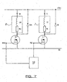
- the actuator includes an electronic driver circuit capable of sending voltage pulses to the coils, such as is shown in Figure 7 .
- the polarity of each connection is selected such that the flux induced by the main 8 and trigger 7 coils is of the same direction in the radial gap 6, and such that the trigger coil acts to demagnetise the permanent magnet 4.
- a digital controller 10 sends signals to the electronic driver circuit such as to actuate the valve at the correct time, possibly synchronized with the shaft of a rotating machine having one or more reciprocating chambers, fluid flow into or from or both into and from said chamber(s) being controlled to some degree by the valve actuation.
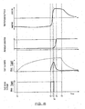
- a voltage pulse is sent to the main coil driver, causing the driver to apply a voltage across the solenoid coil 8, such that current increases in the coil according to the time constant of the coil.
- the large main coil can be "charged up” without removing the force on the armature acting to keep it in position A.
- the trigger coil 7 is energised. Because it has a shorter time constant than the main coil, the current in the trigger coil rises very rapidly, demagnetising the permanent magnet 4 of the latch as it does so. As shown in Figure 5 , the flux in the latch gap 5 is very rapidly eliminated, yet the flux in the main gap 9 is left substantially unaffected. This very rapidly reverses the force balance on the armature 2, which is accelerated towards the position shown in Figure 2 .
- any pulses to the main coil 8 cease, causing the actuation force from the solenoid to reduce until the return force overcomes it and returns the armature to the position of Figure 1 .
- it is advantageous to provide the electronic driver for the main coil with provision to reduce the current in the main coil very quickly, such as by introducing a semiconductor switch in series with the diode Dm, the opening of which will cause the current to decay more quickly than if it were closed.
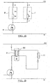
- the circuit of Figure 8 may be employed, whereby the trigger coil 7 is placed in series with the diode D, such that when the main coil 8 is de-energised, a voltage is created which causes current to flow in the trigger coil.
- the circuit of Figure 8 may be employed, whereby the trigger coil 7 is placed in series with the diode D, such that when the main coil 8 is de-energised, a voltage is created which causes current to flow in the trigger coil.
- FIG. 9 An alternative method of realising the same aim as [0041] is shown in Figure 9 .
- the main coil 9 is driven by the electronic driver. Inside the same magnetic circuit as the main coil is placed a third coil 13 ("exciter coil") such that flux which flows through the magnetic circuit of the main coil also flows through the magnetic circuit of the exciter coil.
- the main and exciter coils are therefore in a transformer arrangement whereby positive rate-of-change of current in the main coil will induce a positive voltage across the exciter coil, while a negative rate-of-change of the main coil current will induce a negative voltage across the exciter coil.
- the trigger coil 11 is in series with the exciter coil 13.
- a current is induced in the trigger coil which can be arranged to demagnetise the permanent magnet and cause actuation to take place, given proper choice of both polarity and the number of turns of wire in the exciter and trigger coils.
Landscapes
- Engineering & Computer Science (AREA)
- Physics & Mathematics (AREA)
- Electromagnetism (AREA)
- Power Engineering (AREA)
- Chemical & Material Sciences (AREA)
- Combustion & Propulsion (AREA)
- Mechanical Engineering (AREA)
- General Engineering & Computer Science (AREA)
- Magnetically Actuated Valves (AREA)
- Electromagnets (AREA)
- Reciprocating, Oscillating Or Vibrating Motors (AREA)
Claims (12)
- Elektromagnetisches Betätigungsglied, umfassend einen Kern (1), eine ferromagnetische Komponente (2), welche in einer Aussparung (5) in dem Kern beweglich ist, einen Permanentmagneten (4) zum Anziehen der Komponente zu einer Seite der Aussparung hin, einen Solenoiden (8) zur Erzeugung eins magnetischen Flusses in der Aussparung, um die Komponente zu einer zweiten Seite der Aussparung hin anzuziehen, wobei ein magnetischer Kreis des Solenoiden festgelegt ist durch einen Teil des Kerns (1), durch einen Teil der Aussparung (5) und durch eine weitere Aussparung (6) zwischen der ferromagnetischen Komponente (2) und dem Kern (1), und einen Entmagnetisierer (7), welcher einen magnetischen Kreis aufweist, der einen anderen Teil des Kerns (1), einen anderen Teil der Aussparung (5) und die weitere Aussparung (6) umfasst, wobei der Entmagnetisierer dazu vorgesehen ist, den Permanentmagneten (4) zu entmagnetisieren, damit die bewegliche Komponente unter der magnetischen Kraft des Solenoiden (8) von dem Permanentmagneten weg beweglich ist, dadurch gekennzeichnet, dass ein Flusskonzentrator (12) vorgesehen ist, um den magnetischen Fluss auf der einen Seite der Aussparung (5) zu konzentrieren, und um eine Netto-Kraft von dem Permanentmagneten (4) und dem energetisierenden Solenoiden (8) zu erzeugen, welche die ferromagnetische Komponente (2) auf der einen Seite der Aussparung (5) hält, und dass bei Aktivierung des Entmagnetisierers (7) der von dem Solenoiden (8) erzeugte magnetische Fluss von dem Flusskonzentrator (12) in die weitere Aussparung (6) abgelenkt wird, so dass die bewegliche Komponente (2) unter der magnetischen Kraft des Solenoiden (8) von dem Permanentmagneten weg beweglich ist.
- Betätigungsglied nach Anspruch 1, wobei der Entmagnetisierer (7) eine Spule umfasst, welche eine geringere Latenz aufweist als die Latenz des Solenoiden (8).
- Betätigungsglied nach Anspruch 1 oder 2, umfassend einen elektronischen Steuerkreis, welcher vorgesehen ist, um den Solenoiden (8) und die Spule (7) mit Spannungsimpulsen zu versorgen, so dass sowohl der Solenoid als auch die Spule einen magnetischen Fluss in der gleichen Richtung in einem überlappenden Bereich jedes magnetischen Kreises erzeugen.
- Betätigungsglied nach Anspruch 3, wobei ein digitaler Controller (10) vorgesehen ist, um Signale an den Steuerkreis zu senden, so dass der Solenoid (8) vor einem Zeitpunkt, zu welchem das Betätigungsglied wirken soll, energetisiert wird und die Spule (7) nach dem Solenoiden energetisiert wird.
- Betätigungsglied nach Anspruch 3, wobei ein digitaler Controller (10) vorgesehen ist, um ein Signal an den Steuerkreis zu senden, so dass der Solenoid (8) vor einem Zeitpunkt, zu welchem das Betätigungsglied gegebenenfalls wirken soll, energetisiert wird, wobei die Spule (7) dann nur in Reaktion auf eine Entscheidung, das Betätigungsglied zu betätigen, energetisiert wird.
- Betätigungsglied nach Anspruch 2, umfassend eine Erregerwicklung (13), welche in dem magnetischen Kreis des Solenoiden angeordnet ist, wobei die Erregerwicklung mit der Entmagnetisierer-Spule (7) in Reihe geschaltet ist.
- Betätigungsglied nach einem der vorangehenden Ansprüche, wobei der Flusskonzentrator (12) eine Verjüngung des Permanentmagneten oder eines angrenzenden ferromagnetischen Elements in eine Richtung auf den Solenoiden (8) zu umfasst.
- Betätigungsglied nach einem der vorangehenden Ansprüche, welches im Wesentlichen symmetrisch bezüglich einer Achse ist.
- Betätigungsglied nach einem der Ansprüche 1 bis 7, welches im Wesentlichen symmetrisch bezüglich einer Ebene ist und welches wenigstens zwei Kerne und zwei Magnete, jeweils einen auf jeder Seite der Ebene, umfasst.
- Ventilanordnung für eine Fluid-Arbeits-Maschine, umfassend ein Ventilelement (3), welches an der beweglichen ferromagnetischen Komponente (2) des Betätigungsgliedes nach einem der vorangehenden Ansprüche angebracht ist.
- Fluid-Arbeits-Maschine, bei welcher ein Fluidstrom in eine oder von einer oder sowohl in eine als auch von einer Arbeits-Kammer der Maschine oder in mehrere oder von mehreren oder sowohl in mehrere als auch von mehreren Arbeits-Kammern der Maschine in gewissem Maße durch die Ventilanordnung gemäß Anspruch 10 kontrolliert wird.
- Fluid-Arbeits-Maschine nach Anspruch 11, wobei das Betätigungsglied gemäß Anspruch 5 ausgebildet ist und der digitale Controller (10) mit einer rotierenden Welle der Maschine synchronisiert ist.
Applications Claiming Priority (2)
| Application Number | Priority Date | Filing Date | Title |
|---|---|---|---|
| GBGB0607072.6A GB0607072D0 (en) | 2006-04-07 | 2006-04-07 | Electromagnetic actuator |
| PCT/GB2007/001280 WO2007128977A2 (en) | 2006-04-07 | 2007-04-03 | Electromagnetic actuator |
Publications (2)
| Publication Number | Publication Date |
|---|---|
| EP2005449A2 EP2005449A2 (de) | 2008-12-24 |
| EP2005449B1 true EP2005449B1 (de) | 2014-09-10 |
Family
ID=36539571
Family Applications (1)
| Application Number | Title | Priority Date | Filing Date |
|---|---|---|---|
| EP07732324.4A Not-in-force EP2005449B1 (de) | 2006-04-07 | 2007-04-03 | Elektromagnetisches betätigungsglied |
Country Status (7)
| Country | Link |
|---|---|
| US (1) | US8272622B2 (de) |
| EP (1) | EP2005449B1 (de) |
| JP (1) | JP2009532893A (de) |
| CN (1) | CN101416257B (de) |
| GB (1) | GB0607072D0 (de) |
| RU (1) | RU2008144111A (de) |
| WO (1) | WO2007128977A2 (de) |
Families Citing this family (17)
| Publication number | Priority date | Publication date | Assignee | Title |
|---|---|---|---|---|
| AU2009290640A1 (en) | 2008-09-09 | 2010-03-18 | Artemis Intelligent Power Limited | Valve assemblies |
| EP2182531B1 (de) * | 2008-10-29 | 2014-01-08 | Sauer-Danfoss ApS | Ventilaktuator |
| DE102010005166A1 (de) | 2009-02-12 | 2010-08-19 | Robert Bosch Gmbh | Elektromagnetisch betätigtes Ventil und Hydromaschine |
| CN102439306B (zh) | 2009-04-02 | 2014-12-10 | 胡斯可国际股份有限公司 | 具有由电动液压阀联接于分开的外部端口的气缸的流体工作机 |
| EP2436908A1 (de) * | 2010-09-30 | 2012-04-04 | Continental Automotive GmbH | Ventilanordnung für ein Einspritzventil und Einspritzventil |
| JP5314197B2 (ja) * | 2010-12-21 | 2013-10-16 | 三菱電機株式会社 | 電磁操作装置 |
| US9200648B2 (en) | 2011-01-24 | 2015-12-01 | Purdue Research Foundation | Fluid control valve systems, fluid systems equipped therewith, and methods of using |
| DE102012218325A1 (de) * | 2012-10-09 | 2014-04-10 | Continental Automotive Gmbh | Aktuatoreinheit, insbesondere für die Einspritzung eines Kraftstoffs in einen Brennraum einer Verbrennungskraftmaschine |
| US9658427B2 (en) * | 2013-03-15 | 2017-05-23 | Raytheon Company | Reaction compensated tilt platform |
| CN106663554B (zh) | 2014-05-14 | 2018-06-01 | Abb瑞士股份有限公司 | 以汤姆逊线圈为基础的致动器 |
| US10125892B2 (en) * | 2016-06-13 | 2018-11-13 | Thomas Bentz | Solenoid valve device |
| US10203475B2 (en) | 2016-10-20 | 2019-02-12 | Raytheon Company | Curved magnetic actuators, and systems, and methods for mounting tilt platforms |
| KR102601236B1 (ko) * | 2018-11-30 | 2023-11-13 | 주식회사 씨케이머티리얼즈랩 | 광대역 액추에이터 |
| US11598442B2 (en) * | 2019-05-29 | 2023-03-07 | Denso International America, Inc. | Current dependent bi-directional force solenoid |
| EP4083445B1 (de) | 2021-04-30 | 2025-06-04 | ABB Schweiz AG | Ventil stellungsregler system |
| DE102021205990A1 (de) * | 2021-06-14 | 2022-12-15 | Robert Bosch Gesellschaft mit beschränkter Haftung | Absperrventil für Wasserstofftanksysteme, Druckgasbehälter sowie Wasserstofftanksystem |
| CN120667432B (zh) * | 2025-08-04 | 2026-05-08 | 南昌大学 | 一种永磁旁路磁阻调节的比例作动器 |
Family Cites Families (13)
| Publication number | Priority date | Publication date | Assignee | Title |
|---|---|---|---|---|
| JPS4413461B1 (de) | 1966-05-18 | 1969-06-17 | ||
| GB1237706A (en) * | 1968-05-01 | 1971-06-30 | Hymatic Eng Co Ltd | Improvements relating to electromagnets |
| US4403765A (en) * | 1979-11-23 | 1983-09-13 | John F. Taplin | Magnetic flux-shifting fluid valve |
| US4295111A (en) | 1979-11-29 | 1981-10-13 | Nasa | Low temperature latching solenoid |
| DE3426688A1 (de) * | 1984-07-19 | 1986-01-23 | Siemens Ag | Antriebsanordnung |
| JP2707127B2 (ja) * | 1988-12-28 | 1998-01-28 | 株式会社いすゞセラミックス研究所 | 電磁力バルブ駆動装置 |
| US5034714A (en) | 1989-11-03 | 1991-07-23 | Westinghouse Electric Corp. | Universal relay |
| GB9326245D0 (en) | 1993-12-23 | 1994-02-23 | Perkins Ltd | An improved method for operating a two coil solenoid valve and control circuitry therefor |
| CN2443743Y (zh) * | 2000-10-10 | 2001-08-22 | 上海金盾消防安全设备有限公司 | 一种电磁驱动器 |
| EP1507271A3 (de) * | 2003-08-12 | 2005-04-20 | Japan AE Power Systems Corporation | Elektromagnetische Vorrichtung |
| FR2865238B1 (fr) * | 2004-01-15 | 2006-06-30 | Peugeot Citroen Automobiles Sa | Actionneur electromecanique de commande de soupape pour moteur a combustion interne et moteur a combustion interne muni d'un tel actionneur |
| JP2006108615A (ja) * | 2004-09-07 | 2006-04-20 | Toshiba Corp | 電磁アクチュエータ |
| US7719394B2 (en) * | 2004-10-06 | 2010-05-18 | Victor Nelson | Latching linear solenoid |
-
2006
- 2006-04-07 GB GBGB0607072.6A patent/GB0607072D0/en not_active Ceased
-
2007
- 2007-04-03 CN CN200780012453.4A patent/CN101416257B/zh not_active Expired - Fee Related
- 2007-04-03 RU RU2008144111/09A patent/RU2008144111A/ru not_active Application Discontinuation
- 2007-04-03 JP JP2009503656A patent/JP2009532893A/ja active Pending
- 2007-04-03 WO PCT/GB2007/001280 patent/WO2007128977A2/en not_active Ceased
- 2007-04-03 EP EP07732324.4A patent/EP2005449B1/de not_active Not-in-force
- 2007-04-03 US US12/296,183 patent/US8272622B2/en not_active Expired - Fee Related
Also Published As
| Publication number | Publication date |
|---|---|
| CN101416257B (zh) | 2013-04-24 |
| JP2009532893A (ja) | 2009-09-10 |
| US8272622B2 (en) | 2012-09-25 |
| GB0607072D0 (en) | 2006-05-17 |
| WO2007128977A2 (en) | 2007-11-15 |
| RU2008144111A (ru) | 2010-05-20 |
| EP2005449A2 (de) | 2008-12-24 |
| WO2007128977A3 (en) | 2008-01-10 |
| CN101416257A (zh) | 2009-04-22 |
| US20090302251A1 (en) | 2009-12-10 |
Similar Documents
| Publication | Publication Date | Title |
|---|---|---|
| US8272622B2 (en) | Electromagnetic actuator | |
| JP3629362B2 (ja) | エンジンバルブ駆動用電磁バルブの駆動方法 | |
| EP2182531B1 (de) | Ventilaktuator | |
| US4779582A (en) | Bistable electromechanical valve actuator | |
| EP0395450B1 (de) | Antriebsvorrichtung für Einlass- oder Auslassventile | |
| US5249603A (en) | Proportional electro-hydraulic pressure control device | |
| JP6409131B2 (ja) | 複合磁気回路ダブル永久磁石電磁石及び複合磁気回路ダブル永久磁石高速電磁弁 | |
| EP0422228B1 (de) | Elektromagnetischer ventilbetätiger | |
| CN110891835B (zh) | 用于液压制动系统的双稳态的电磁阀以及用于操控这种阀的方法 | |
| US6176207B1 (en) | Electronically controlling the landing of an armature in an electromechanical actuator | |
| US9607746B2 (en) | Electromagnetic actuator device | |
| EP0405191A1 (de) | Elektromagnetisch arbeitende Stelleinrichtung | |
| US5682127A (en) | Method of switching an electromagnetic actuator | |
| JP5025889B2 (ja) | 内燃機関用のバルブの電気機械式アクチュエータ、およびそのようなアクチュエータを具備する内燃機関 | |
| CN109595382B (zh) | 一种控制滑动凸轮位移的多执行器电磁阀 | |
| JP2673370B2 (ja) | バルブの駆動装置 | |
| US12494312B2 (en) | Fast-acting toggling armature uses centring spring | |
| KR101362262B1 (ko) | 하이브리드 자석 엔진 밸브 액츄에이터 | |
| JP2697052B2 (ja) | 電磁駆動バルブ | |
| JP2009019619A (ja) | 電磁駆動バルブ装置 | |
| EP4649510A1 (de) | Elektromagnetischer aktuator | |
| EP1049114A2 (de) | Verfahren zur Steuerung eines Ankers eines elektromagnetisches Hochgeschwindigkeitsbedienungselement | |
| JPH0115750B2 (de) | ||
| CA2195696A1 (en) | Fail-safe actuator with two permanent magnets |
Legal Events
| Date | Code | Title | Description |
|---|---|---|---|
| PUAI | Public reference made under article 153(3) epc to a published international application that has entered the european phase |
Free format text: ORIGINAL CODE: 0009012 |
|
| 17P | Request for examination filed |
Effective date: 20080922 |
|
| AK | Designated contracting states |
Kind code of ref document: A2 Designated state(s): AT BE BG CH CY CZ DE DK EE ES FI FR GB GR HU IE IS IT LI LT LU LV MC MT NL PL PT RO SE SI SK TR |
|
| 17Q | First examination report despatched |
Effective date: 20090218 |
|
| DAX | Request for extension of the european patent (deleted) | ||
| GRAP | Despatch of communication of intention to grant a patent |
Free format text: ORIGINAL CODE: EPIDOSNIGR1 |
|
| INTG | Intention to grant announced |
Effective date: 20140409 |
|
| GRAS | Grant fee paid |
Free format text: ORIGINAL CODE: EPIDOSNIGR3 |
|
| GRAA | (expected) grant |
Free format text: ORIGINAL CODE: 0009210 |
|
| AK | Designated contracting states |
Kind code of ref document: B1 Designated state(s): AT BE BG CH CY CZ DE DK EE ES FI FR GB GR HU IE IS IT LI LT LU LV MC MT NL PL PT RO SE SI SK TR |
|
| REG | Reference to a national code |
Ref country code: GB Ref legal event code: FG4D |
|
| REG | Reference to a national code |
Ref country code: CH Ref legal event code: EP |
|
| REG | Reference to a national code |
Ref country code: IE Ref legal event code: FG4D |
|
| REG | Reference to a national code |
Ref country code: AT Ref legal event code: REF Ref document number: 687061 Country of ref document: AT Kind code of ref document: T Effective date: 20141015 |
|
| REG | Reference to a national code |
Ref country code: DE Ref legal event code: R096 Ref document number: 602007038487 Country of ref document: DE Effective date: 20141016 |
|
| PG25 | Lapsed in a contracting state [announced via postgrant information from national office to epo] |
Ref country code: FI Free format text: LAPSE BECAUSE OF FAILURE TO SUBMIT A TRANSLATION OF THE DESCRIPTION OR TO PAY THE FEE WITHIN THE PRESCRIBED TIME-LIMIT Effective date: 20140910 Ref country code: GR Free format text: LAPSE BECAUSE OF FAILURE TO SUBMIT A TRANSLATION OF THE DESCRIPTION OR TO PAY THE FEE WITHIN THE PRESCRIBED TIME-LIMIT Effective date: 20141211 Ref country code: SE Free format text: LAPSE BECAUSE OF FAILURE TO SUBMIT A TRANSLATION OF THE DESCRIPTION OR TO PAY THE FEE WITHIN THE PRESCRIBED TIME-LIMIT Effective date: 20140910 Ref country code: LT Free format text: LAPSE BECAUSE OF FAILURE TO SUBMIT A TRANSLATION OF THE DESCRIPTION OR TO PAY THE FEE WITHIN THE PRESCRIBED TIME-LIMIT Effective date: 20140910 Ref country code: ES Free format text: LAPSE BECAUSE OF FAILURE TO SUBMIT A TRANSLATION OF THE DESCRIPTION OR TO PAY THE FEE WITHIN THE PRESCRIBED TIME-LIMIT Effective date: 20140910 |
|
| REG | Reference to a national code |
Ref country code: NL Ref legal event code: VDEP Effective date: 20140910 |
|
| REG | Reference to a national code |
Ref country code: LT Ref legal event code: MG4D |
|
| PG25 | Lapsed in a contracting state [announced via postgrant information from national office to epo] |
Ref country code: LV Free format text: LAPSE BECAUSE OF FAILURE TO SUBMIT A TRANSLATION OF THE DESCRIPTION OR TO PAY THE FEE WITHIN THE PRESCRIBED TIME-LIMIT Effective date: 20140910 Ref country code: CY Free format text: LAPSE BECAUSE OF FAILURE TO SUBMIT A TRANSLATION OF THE DESCRIPTION OR TO PAY THE FEE WITHIN THE PRESCRIBED TIME-LIMIT Effective date: 20140910 |
|
| REG | Reference to a national code |
Ref country code: AT Ref legal event code: MK05 Ref document number: 687061 Country of ref document: AT Kind code of ref document: T Effective date: 20140910 |
|
| PG25 | Lapsed in a contracting state [announced via postgrant information from national office to epo] |
Ref country code: NL Free format text: LAPSE BECAUSE OF FAILURE TO SUBMIT A TRANSLATION OF THE DESCRIPTION OR TO PAY THE FEE WITHIN THE PRESCRIBED TIME-LIMIT Effective date: 20140910 |
|
| REG | Reference to a national code |
Ref country code: FR Ref legal event code: PLFP Year of fee payment: 9 |
|
| PG25 | Lapsed in a contracting state [announced via postgrant information from national office to epo] |
Ref country code: EE Free format text: LAPSE BECAUSE OF FAILURE TO SUBMIT A TRANSLATION OF THE DESCRIPTION OR TO PAY THE FEE WITHIN THE PRESCRIBED TIME-LIMIT Effective date: 20140910 Ref country code: CZ Free format text: LAPSE BECAUSE OF FAILURE TO SUBMIT A TRANSLATION OF THE DESCRIPTION OR TO PAY THE FEE WITHIN THE PRESCRIBED TIME-LIMIT Effective date: 20140910 Ref country code: IS Free format text: LAPSE BECAUSE OF FAILURE TO SUBMIT A TRANSLATION OF THE DESCRIPTION OR TO PAY THE FEE WITHIN THE PRESCRIBED TIME-LIMIT Effective date: 20150110 Ref country code: SK Free format text: LAPSE BECAUSE OF FAILURE TO SUBMIT A TRANSLATION OF THE DESCRIPTION OR TO PAY THE FEE WITHIN THE PRESCRIBED TIME-LIMIT Effective date: 20140910 Ref country code: PT Free format text: LAPSE BECAUSE OF FAILURE TO SUBMIT A TRANSLATION OF THE DESCRIPTION OR TO PAY THE FEE WITHIN THE PRESCRIBED TIME-LIMIT Effective date: 20150112 Ref country code: RO Free format text: LAPSE BECAUSE OF FAILURE TO SUBMIT A TRANSLATION OF THE DESCRIPTION OR TO PAY THE FEE WITHIN THE PRESCRIBED TIME-LIMIT Effective date: 20140910 |
|
| PG25 | Lapsed in a contracting state [announced via postgrant information from national office to epo] |
Ref country code: AT Free format text: LAPSE BECAUSE OF FAILURE TO SUBMIT A TRANSLATION OF THE DESCRIPTION OR TO PAY THE FEE WITHIN THE PRESCRIBED TIME-LIMIT Effective date: 20140910 Ref country code: PL Free format text: LAPSE BECAUSE OF FAILURE TO SUBMIT A TRANSLATION OF THE DESCRIPTION OR TO PAY THE FEE WITHIN THE PRESCRIBED TIME-LIMIT Effective date: 20140910 |
|
| REG | Reference to a national code |
Ref country code: DE Ref legal event code: R097 Ref document number: 602007038487 Country of ref document: DE |
|
| PLBE | No opposition filed within time limit |
Free format text: ORIGINAL CODE: 0009261 |
|
| STAA | Information on the status of an ep patent application or granted ep patent |
Free format text: STATUS: NO OPPOSITION FILED WITHIN TIME LIMIT |
|
| PG25 | Lapsed in a contracting state [announced via postgrant information from national office to epo] |
Ref country code: DK Free format text: LAPSE BECAUSE OF FAILURE TO SUBMIT A TRANSLATION OF THE DESCRIPTION OR TO PAY THE FEE WITHIN THE PRESCRIBED TIME-LIMIT Effective date: 20140910 |
|
| 26N | No opposition filed |
Effective date: 20150611 |
|
| PG25 | Lapsed in a contracting state [announced via postgrant information from national office to epo] |
Ref country code: IT Free format text: LAPSE BECAUSE OF FAILURE TO SUBMIT A TRANSLATION OF THE DESCRIPTION OR TO PAY THE FEE WITHIN THE PRESCRIBED TIME-LIMIT Effective date: 20140910 |
|
| PG25 | Lapsed in a contracting state [announced via postgrant information from national office to epo] |
Ref country code: SI Free format text: LAPSE BECAUSE OF FAILURE TO SUBMIT A TRANSLATION OF THE DESCRIPTION OR TO PAY THE FEE WITHIN THE PRESCRIBED TIME-LIMIT Effective date: 20140910 Ref country code: LU Free format text: LAPSE BECAUSE OF FAILURE TO SUBMIT A TRANSLATION OF THE DESCRIPTION OR TO PAY THE FEE WITHIN THE PRESCRIBED TIME-LIMIT Effective date: 20150403 Ref country code: MC Free format text: LAPSE BECAUSE OF FAILURE TO SUBMIT A TRANSLATION OF THE DESCRIPTION OR TO PAY THE FEE WITHIN THE PRESCRIBED TIME-LIMIT Effective date: 20140910 |
|
| REG | Reference to a national code |
Ref country code: CH Ref legal event code: PL |
|
| REG | Reference to a national code |
Ref country code: IE Ref legal event code: MM4A |
|
| PG25 | Lapsed in a contracting state [announced via postgrant information from national office to epo] |
Ref country code: LI Free format text: LAPSE BECAUSE OF NON-PAYMENT OF DUE FEES Effective date: 20150430 Ref country code: CH Free format text: LAPSE BECAUSE OF NON-PAYMENT OF DUE FEES Effective date: 20150430 |
|
| REG | Reference to a national code |
Ref country code: FR Ref legal event code: PLFP Year of fee payment: 10 |
|
| PG25 | Lapsed in a contracting state [announced via postgrant information from national office to epo] |
Ref country code: IE Free format text: LAPSE BECAUSE OF NON-PAYMENT OF DUE FEES Effective date: 20150403 |
|
| PG25 | Lapsed in a contracting state [announced via postgrant information from national office to epo] |
Ref country code: BE Free format text: LAPSE BECAUSE OF FAILURE TO SUBMIT A TRANSLATION OF THE DESCRIPTION OR TO PAY THE FEE WITHIN THE PRESCRIBED TIME-LIMIT Effective date: 20140910 |
|
| PG25 | Lapsed in a contracting state [announced via postgrant information from national office to epo] |
Ref country code: MT Free format text: LAPSE BECAUSE OF FAILURE TO SUBMIT A TRANSLATION OF THE DESCRIPTION OR TO PAY THE FEE WITHIN THE PRESCRIBED TIME-LIMIT Effective date: 20140910 |
|
| REG | Reference to a national code |
Ref country code: FR Ref legal event code: PLFP Year of fee payment: 11 |
|
| PG25 | Lapsed in a contracting state [announced via postgrant information from national office to epo] |
Ref country code: BG Free format text: LAPSE BECAUSE OF FAILURE TO SUBMIT A TRANSLATION OF THE DESCRIPTION OR TO PAY THE FEE WITHIN THE PRESCRIBED TIME-LIMIT Effective date: 20140910 Ref country code: HU Free format text: LAPSE BECAUSE OF FAILURE TO SUBMIT A TRANSLATION OF THE DESCRIPTION OR TO PAY THE FEE WITHIN THE PRESCRIBED TIME-LIMIT; INVALID AB INITIO Effective date: 20070403 |
|
| PG25 | Lapsed in a contracting state [announced via postgrant information from national office to epo] |
Ref country code: TR Free format text: LAPSE BECAUSE OF FAILURE TO SUBMIT A TRANSLATION OF THE DESCRIPTION OR TO PAY THE FEE WITHIN THE PRESCRIBED TIME-LIMIT Effective date: 20140910 |
|
| REG | Reference to a national code |
Ref country code: FR Ref legal event code: PLFP Year of fee payment: 12 |
|
| PGFP | Annual fee paid to national office [announced via postgrant information from national office to epo] |
Ref country code: GB Payment date: 20220303 Year of fee payment: 16 |
|
| PGFP | Annual fee paid to national office [announced via postgrant information from national office to epo] |
Ref country code: FR Payment date: 20220321 Year of fee payment: 16 |
|
| PGFP | Annual fee paid to national office [announced via postgrant information from national office to epo] |
Ref country code: DE Payment date: 20220302 Year of fee payment: 16 |
|
| REG | Reference to a national code |
Ref country code: DE Ref legal event code: R119 Ref document number: 602007038487 Country of ref document: DE |
|
| GBPC | Gb: european patent ceased through non-payment of renewal fee |
Effective date: 20230403 |
|
| PG25 | Lapsed in a contracting state [announced via postgrant information from national office to epo] |
Ref country code: GB Free format text: LAPSE BECAUSE OF NON-PAYMENT OF DUE FEES Effective date: 20230403 |
|
| PG25 | Lapsed in a contracting state [announced via postgrant information from national office to epo] |
Ref country code: GB Free format text: LAPSE BECAUSE OF NON-PAYMENT OF DUE FEES Effective date: 20230403 Ref country code: FR Free format text: LAPSE BECAUSE OF NON-PAYMENT OF DUE FEES Effective date: 20230430 Ref country code: DE Free format text: LAPSE BECAUSE OF NON-PAYMENT OF DUE FEES Effective date: 20231103 |