EP2005112B1 - Vorrichtung und Verfahren zum dreidimensionalen Erfassen eines Raumbereichs - Google Patents
Vorrichtung und Verfahren zum dreidimensionalen Erfassen eines Raumbereichs Download PDFInfo
- Publication number
- EP2005112B1 EP2005112B1 EP06723968.1A EP06723968A EP2005112B1 EP 2005112 B1 EP2005112 B1 EP 2005112B1 EP 06723968 A EP06723968 A EP 06723968A EP 2005112 B1 EP2005112 B1 EP 2005112B1
- Authority
- EP
- European Patent Office
- Prior art keywords
- image
- image capturing
- unit
- capturing unit
- axis
- Prior art date
- Legal status (The legal status is an assumption and is not a legal conclusion. Google has not performed a legal analysis and makes no representation as to the accuracy of the status listed.)
- Not-in-force
Links
Images


Classifications
-
- G—PHYSICS
- G01—MEASURING; TESTING
- G01S—RADIO DIRECTION-FINDING; RADIO NAVIGATION; DETERMINING DISTANCE OR VELOCITY BY USE OF RADIO WAVES; LOCATING OR PRESENCE-DETECTING BY USE OF THE REFLECTION OR RERADIATION OF RADIO WAVES; ANALOGOUS ARRANGEMENTS USING OTHER WAVES
- G01S17/00—Systems using the reflection or reradiation of electromagnetic waves other than radio waves, e.g. lidar systems
- G01S17/88—Lidar systems specially adapted for specific applications
- G01S17/89—Lidar systems specially adapted for specific applications for mapping or imaging
-
- G—PHYSICS
- G01—MEASURING; TESTING
- G01C—MEASURING DISTANCES, LEVELS OR BEARINGS; SURVEYING; NAVIGATION; GYROSCOPIC INSTRUMENTS; PHOTOGRAMMETRY OR VIDEOGRAMMETRY
- G01C15/00—Surveying instruments or accessories not provided for in groups G01C1/00 - G01C13/00
- G01C15/002—Active optical surveying means
-
- G—PHYSICS
- G01—MEASURING; TESTING
- G01S—RADIO DIRECTION-FINDING; RADIO NAVIGATION; DETERMINING DISTANCE OR VELOCITY BY USE OF RADIO WAVES; LOCATING OR PRESENCE-DETECTING BY USE OF THE REFLECTION OR RERADIATION OF RADIO WAVES; ANALOGOUS ARRANGEMENTS USING OTHER WAVES
- G01S17/00—Systems using the reflection or reradiation of electromagnetic waves other than radio waves, e.g. lidar systems
- G01S17/86—Combinations of lidar systems with systems other than lidar, radar or sonar, e.g. with direction finders
Definitions
- the present invention relates to a device for three-dimensional detection of a spatial region having the features of the preamble of claim 1 and a method having the features of the preamble of claim 15.
- a device with a rangefinder and a beam pivoting unit and a corresponding method are out DE 202 08 077 U1 known.
- This device uses a laser beam, which is deflected by means of a rotating mirror in different spatial directions.
- the mirror rotates about a horizontal axis of rotation and is inclined with respect to the axis of rotation by about 45 °, so that the laser beam sweeps over a vertical surface area.
- the measuring head with the transmitter, receiver and the rotating mirror is rotated about a vertical axis.
- the known device can almost completely scan a room area. Only downwards is the laser beam restricted by the housing of the measuring head and / or the footprint.
- the known device can record a three-dimensional distance image of a room or room area.
- Preferred applications for such a device are, for example, the measurement of tunnel tubes, buildings, monuments or the leadership of driverless transport systems.
- dimensions within the room or room area can also be subsequently determined on the basis of the recorded data.
- the pure distance data is unfavorable for a visual impression of the recorded space area.
- the known device also determines intensity values of the reflection signal, with which it is possible to generate intensity images that are roughly comparable to a black-and-white image of the space or spatial region. Although this already gives a good visual impression of a recorded space, there is a desire to make three-dimensional recording and playback even more realistic.
- the EP 1 347 267 A1 Devices of the aforementioned type which additionally have image recording units.
- the image acquisition units use the same optics and control device as the rangefinder.
- the beam pivot unit has a horizontal and a vertical drive.
- a device for use in an aircraft is proposed to arrange an image acquisition unit with a line sensor as an image sensor parallel to the range finder and to combine the measurement data with the data of further sensors.
- a line sensor has a plurality of cell-shaped juxtaposed image cells.
- the US 202/0059042 A1 Proposes to combine the consisting of rangefinder and Strahlschwenkiata scanner with a CCD video camera as an image recording unit and offer the user both representations of the space area.
- a distance measuring device and a beam pivoting unit are provided with an image recording unit or "camera” with the aid of which a "normal” photograph of the spatial area can be made. It is a digital image acquisition unit, so that the image data are in digital form and can be stored together with the typically also digital distance information.
- the image recording unit is coupled to the beam swiveling unit in such a way that the spatial area recorded by the image recording unit can be accurately associated with the distance information of the rangefinder.
- the distance information of the rangefinder can be very easily and accurately brought into line with the purely visual image information of the image pickup unit.
- the result is a combination of a very realistic image of the captured space, as one is used to from photographic images.
- the quality of such an image is higher than the optical impression, which can be derived from the intensity image of the rangefinder.
- the new device in addition to the high quality optical image, the new device also provides the distance information to the object points, and thus offers all the advantages and capabilities of the known device.
- the beam pivot unit has a first rotary drive in order to rotate the beam-shaped transmission signal about a first, preferably vertical axis of rotation.
- This embodiment simplifies the recording of a panorama image or all-around image of the spatial area with the aid of the new image recording unit.
- this embodiment allows a very simple detection of the space area over a 360 ° angle in the azimuth.
- the image acquisition unit has an image sensor with a plurality of cell-like juxtaposed image cells (pixels) forming a picture cell row, wherein the image cell row is positionable parallel to the first rotation axis.
- This embodiment includes, on the one hand, implementations in which the image acquisition unit is arranged in a fixed position relative to the rangefinder, and realizations in which the image acquisition unit is pivotable or otherwise variable with respect to the range finder. Accordingly, the image cell row may be permanently parallel to the first axis of rotation, or it may be pivoted to such an orientation only for image capture.
- the image sensor is a line sensor.
- Line sensors in the sense of this embodiment are image sensors which have only a small number of lines or columns with image cells for receiving image information.
- a line sensor for monochrome image capture black and white has only a single row or column of image cells.
- a preferred line sensor for receiving a colored image of the spatial region has three image cell lines parallel to one another, wherein a first image cell line for receiving a first color component (eg red), a second image cell line for receiving a second color component (eg green) and a third image cell line for receiving a third color component (eg blue) is provided.
- a first image cell line for receiving a first color component eg red
- a second image cell line for receiving a second color component eg green
- a third image cell line for receiving a third color component eg blue
- the image information of the image acquisition unit can be read very easily and quickly in this embodiment and assigned to the distance information of the rangefinder. Furthermore, this design contributes to reducing the size of the image files without sacrificing image quality.
- the image sensor has a plurality of mutually parallel image cell rows for receiving different color components, wherein the parallel image cell rows are each arranged at a defined distance from each other, and wherein the first rotary drive has a rotational speed which is adapted to the defined distance, so that each of the parallel Image cell lines receives the same object points.
- This embodiment is particularly advantageous in connection with an image sensor having three parallel image cell rows for receiving three different color components or different colored line images, in particular for recording a red, a green and a blue line image of the spatial area.
- an image sensor having three parallel image cell rows for receiving three different color components or different colored line images, in particular for recording a red, a green and a blue line image of the spatial area.
- This embodiment which records a colored optical image of the spatial area, an even more realistic detection of the spatial area is achieved. Individual details within the room area can be assessed even more precisely on the basis of the captured image information.
- the three color images can be superimposed very simply and, above all, precisely matched, in order to obtain a "colorful" image of the spatial area in this way. It is particularly preferred in this embodiment, if the rotational speed of the first rotary drive in dependence on the distance of the image cell rows, the existing or set line resolution in the image recording and / or in dependence on the exposure time, which is required for a single line recording, is adjustable, because in this embodiment, an optimal image quality depending on the environmental situation can be achieved.
- the new device offers a cost-effective way to capture a room area with a high level of detail three-dimensionally and play realistic. The above object is therefore completely solved.
- the image recording unit is designed to record a thermal image of the spatial region or also an image of the spatial region in other wavelength ranges.
- the image acquisition unit has in particular the ability to record an infrared image of the spatial area. This allows further properties of the room area to be captured and documented for later evaluation. The range of application of the new device is further increased in an advantageous manner.
- the evaluation and control unit is designed to determine a gray scale image of the spatial region on the basis of signal amplitudes of the reflection signal.
- This embodiment is also already realized in the known device. It has, in combination with the present invention, the particular advantage that the image information taken with the image acquisition unit can be compared with the "image information" of the rangefinder in order to obtain further conclusions about the properties of the acquired spatial region. In particular, by comparing a colored optical image with the grayscale image of the rangefinder conclusions about the reflection properties and thus conclusions about material properties of objects in the space area can be made.
- the evaluation and control unit is further configured to superimpose the gray scale image and the image of the image acquisition unit accurately (and preferably completely, ie for each measurement point of the rangefinder).
- this embodiment makes it possible to "color" the grayscale image in which each pixel is assigned a distance information with the optical image of the image acquisition unit in order to obtain an extremely realistic image with additional distance information for each object point.
- the beam pivoting unit has a second rotary drive in order to rotate the transmission signal about a second, preferably horizontal axis of rotation.
- This embodiment allows a nearly complete detection of a space in the azimuth and in the elevation in a very simple manner.
- the image cell row can be positioned perpendicular to the second axis of rotation.
- serially read-out image cells can be assigned very well to the object points which are scanned with a transmission signal rotated about the second rotation axis.
- the first and second axes of rotation define an intercept point
- the image capturing unit has an optical axis that is positionable, at least selectively, in the region of the intercept point.
- the image pickup unit is positionable so that its optical axis passes through the axis intersection of the two axes of rotation.
- the device includes a height-adjustable stand with a height scale for accurately positioning the image pickup unit.
- the inventive combination of the image pickup unit with the rangefinder is difficult in the practical realization in that the image pickup unit can affect the field of view of the rangefinder. This is particularly true when the image pickup unit is to be brought with its optical axis in the range of the intercept point.
- the preferred embodiment makes it possible to arrange the image pickup unit above or below the axis intersection point. With the aid of the height scaling, the deviation can be compensated by first recording the distance image without image acquisition unit in a first pass and then recording the optical image in a second pass, wherein the stand (for example: a three-legged tripod or a height-adjustable pillar) between the two Passages is lowered or raised just enough so that the image pickup unit passes into the axial intersection of the axes of rotation of the first pass.
- the design is a very simple and inexpensive way to combine the image pickup unit and the rangefinder in one device.
- the beam pivoting unit includes a rotating mirror, which is designed to deflect the transmission signal in different spatial directions, wherein the image recording unit is at least selectively positionable in the region of the rotating mirror.
- This embodiment is a particularly elegant way to integrate an image pickup unit in a device of the type described above. Because the image recording unit can be positioned in the region of the rotating mirror, parallax errors can be reduced to a minimum in a very simple manner.
- the device has a housing structure with at least two separate housing parts, and it has a holder for the image pickup unit, which is detachably connected to at least one housing part.
- This embodiment makes it possible to operate the new device optionally with or without an image recording unit, so that the image recording unit can optionally be used. Furthermore, older devices with this configuration can be easily retrofitted with the new image acquisition unit.
- the holder has a pivotable arm on which the image recording unit is arranged, and preferably also detachably.
- This embodiment has proved in practical embodiments as a very simple and robust way, which allows both a simple operation and high accuracy in the superimposition or assignment of the image information and distance information.
- the holder has an approximately U-shaped bracket toberichtstecken the holder on the at least one housing part.
- This embodiment has proven to be a very simple and advantageous solution to retrofit existing devices with the new image acquisition unit.
- the image recording unit with the aid of the holder is pivotable in a plane which lies between the at least two housing parts.
- the axis of rotation of the first rotary drive extends in this plane, so that the image sensor with the holder is positioned approximately congruent to the axis of rotation.
- This embodiment has the advantage that on the one hand the image recording unit can be brought very close to the center of the new device, which usually defines the origin of the coordinates for the rangefinder. On the other hand, the image recording unit can also be simply swung out of this area, whereby the rangefinder receives a largely free view of the object points of the spatial area.
- This embodiment therefore combines a relatively simple, inexpensive and robust construction with the possibility of placing the image acquisition unit almost optimally in the center of the new device.
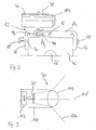
- FIGS. 1 to 4 a preferred embodiment of the new device is designated in its entirety by the reference numeral 10.
- the device 10 includes a transmitter 12 and a receiver 14, both of which are connected to an evaluation and control unit 16.
- the transmitter 12 includes a laser diode configured to emit a laser beam 18 to illuminate an object point 20 in the spatial domain.
- the laser beam 18 modulated.
- the invention is not limited to such types of range finders.
- the transmission signal could also be an ultrasonic signal or another optical or electromagnetic signal.
- the laser beam 18 is deflected in this embodiment via a mirror 22 to the object point 20.
- the reference numeral 24 denotes a reflected beam, which is reflected by the object point 20 and is deflected via the mirror 22 to the receiver 14.
- the evaluation and control unit 16 is here able to determine the distance of the device 10 to the object point 20 from the transit time of the emitted laser beam 18 and the received reflected beam 24. For this purpose, the time difference between the two signals is evaluated based on phase angles and / or pulses. Accordingly, the transmitter 12, the receiver 14 and the evaluation and control unit 16 form a rangefinder.
- the mirror 22 is formed here on the front end face of a cylinder 26 which is connected via a shaft 28 with a rotary drive 30. With the aid of the rotary drive 30, the mirror 22 can be rotated about a rotation axis 32. The respective rotational position of the mirror 22 can be determined with the aid of an encoder 34. The output signals of the encoder 34 are also supplied to the evaluation and control unit 16 (not shown here for reasons of clarity).
- the axis of rotation 32 is arranged horizontally and the mirror 22 is inclined relative to the axis of rotation 32 at an angle of approximately 45 °.
- a rotation of the mirror 22 about the horizontal axis 32 thus has the consequence the laser beam 18 is deflected along a vertical plane which is perpendicular to the axis of rotation 32.
- the laser beam 18 effectively forms a fan with which the spatial region 36 is scanned in a vertical plane.
- the device 10 has a housing structure which has essentially two housing parts 38, 40 which are arranged on a common base plate 42.
- the in Fig. 1 left housing part 38 of the transmitter 12, the receiver 14 and the evaluation and control unit 16 are housed.
- the in Fig. 1 right housing part 40 accommodates the rotary drive 30 with the encoder 34 and the cylinder 26, wherein the cylinder 26 protrudes with the mirror 22 from the housing part 40, so that the mirror 22 is arranged approximately centrally between the two housing parts 38, 40.
- the two housing parts 38, 40 each have a reinforced side wall 44 and 46, which are parallel to each other and limit the gap 48 between the housing parts 38, 40.
- the side wall 44 has an opening 50, through which the laser beam 18 can pass out of the housing part 38 to the outside and the reflected beam 24 can again enter the housing part 38.
- the opening 50 is closed in preferred embodiments of the invention with a window to prevent the ingress of dirt into the housing part 38.
- the housing wall 46 has an opening 52, through which the cylinder 26 projects into the intermediate space 48.
- the side walls 44, 46 form the supporting parts of the housing structure which are fixedly connected to the base plate 42, while the housing parts 38, 40 from the base plate 42 and the side walls 44, 46 can be removed.
- the base plate 42 is arranged on a rotary drive 54, which in turn sits on a stand 56.
- the stand 56 is adjustable in height and has a scale 58 in order to make an exact and reproducible height adjustment.
- the reference numeral 60 denotes an encoder, with the aid of which the rotational position of the rotary drive 54 can be determined.
- the output signals of the encoder 60 are also fed to the evaluation and control unit 16 (not shown here).
- the rotary drive 54 allows rotation of the device 10 about a vertical axis of rotation 62, which defines an axis intersection point 64 together with the axis of rotation 32.
- the intersection point 64 lies approximately in the middle of the mirror 22 and defines in preferred embodiments of the invention the origin of a coordinate system to which all distance measurement values of the rangefinder are related. In the preferred embodiment, the intersection point 64 is located approximately centrally in the gap 48 between the sidewalls 44, 46.
- the "scanning fan”, which is generated by means of the rotary drive 30 can be rotated by up to 360 ° in the azimuth.
- the laser beam 18 can illuminate almost every object point 20 in the vicinity of the device 10. Shading takes place only downwards through the base plate 42, so that the viewing angle of the rangefinder is limited downwards to about 70 ° relative to the vertical.
- the reference numeral 70 denotes an image pickup unit which, in this embodiment, has a line sensor 72 with a plurality of image cells 74 arranged side by side in a row.
- the line sensor 72 has three parallel juxtaposed image cell lines 72a, 72b, 72c, which are arranged at a relative distance from each other that is approximately the width of three to ten image cells 74 (not shown to scale).
- another color filter (not shown here) is arranged so that the picture cell rows 72a, 72b, 72c receive differently colored line images, which together give an RGB color line picture. Further details of the image acquisition unit 70 are shown below Fig. 3 described.
- the image recording unit 70 is here attached via a pin 76 releasably attached to a pivot arm 78.
- the pivot arm 78 is L-shaped, wherein the image pickup unit 70 is disposed on a first leg of the pivot arm 78.
- the second leg of the pivot arm 78 is pivotally mounted with a pin 80 on a holder 82.
- Fig. 1 shows the image pickup unit 70 in a first pivotal position of the pivot arm 78.
- Fig. 4 shows the image pickup unit 70 in a second pivot position, the image pickup unit 70 here at least partially protrudes into the gap 48 between the side walls 44, 46.
- Fig. 2 shows the holder 82 with the image pickup unit 70 in a side view of the side wall 46.
- the holder 82 includes an approximately U-shaped bracket 84 which is slid onto the side wall 46 from above is.
- the lateral legs 86 of the bracket 84 engage around the upper portion of the side wall 46. They are fixed by means of clamping screws 88 which engage corresponding bores 90 on the bracket 84 and, in preferred embodiments, in the side wall 46.
- the clip 84 can be pulled upwardly away from the side wall 46 so that the entire holder 82 with the image pickup unit 70 can be separated from the remaining device 10.
- the bracket 84 has a slot 92 through which a pin 94 projects, which is connected via an intermediate part 96 with the pivot arm 78.
- the pin 94 is fixed to the bracket 84 via a nut.
- the image recording unit 70 here has a tube 100 in which the line sensor 72 is arranged. Furthermore, a memory 102 is accommodated in the tube 100, in which the image data of the line sensor 72 are buffered. The memory 102 is connected to the evaluation and control unit 16 (not shown here).
- the image acquisition unit 70 has optics with a so-called fisheye objective 104, which enables a very large image acquisition area 106.
- the image pickup area 106 ranges from about -70 ° to about + 70 ° with respect to the optical axis 108 of the image pickup unit 70.
- the line sensor 72 has a resolution of about 5000 pixels in the preferred embodiment.
- FIG. 12 shows the image capture unit 70 in a pivot position that enables interference-free ranging with the device 10 in a first data acquisition pass.
- the mirror 22 is rotated about the axis of rotation 32 while the device 10 is rotated about the vertical axis 62.
- the transmitter 12 emits the modulated laser beam 18, which scans the spatial region 36 around the device 10 due to the two rotational movements.
- the evaluation and control unit 16 determines the distance to each object point 20 with respect to the intersection point 64.
- the evaluation and Control unit 16 evaluates the evaluation and Control unit 16, the amplitude of the reflected rays 24 to each object point 20 to generate an intensity image or a gray scale image of the space region 36.
- the transmitter 12 is turned off.
- the image pickup unit 70 is inserted by means of the holder 82 in the in Fig. 4 shown position brought. As shown therein, the holder 82 is formed so that the line sensor 72 is positioned in this position parallel to the axis of rotation 62 and approximately centrally and congruent thereto.
- the optical axis 108 is then aligned with the axis of rotation 62, but intersects them at a right angle. However, the image acquisition unit 70 is still slightly higher than the intercept point 64 in the acquisition of the distance values.
- the entire apparatus 10 is moved downwardly by means of the tripod 56, namely by the distance D, which corresponds approximately to the vertical distance of the optical axis 108 to the intersection point 64.
- the device 10 is moved by means of the rotary drive 54 a second time circulating, wherein the image pickup unit 70 scans the surrounding space area 36 line by line and receives.
- the image data from the line sensor 72 are temporarily stored in the intermediate memory 102 and fed to the evaluation and control unit 16.
- the evaluation and control unit 16 can then (completely) superimpose the data of the rangefinder and the image data of the image acquisition unit 70, especially with respect to all pixels, because parallax errors between the rangefinder and the image acquisition unit are avoided.
- the evaluation and control unit 16 is adapted to automatically superimpose the grayscale image of the rangefinder and the line-by-line recorded image from the image acquisition unit, the information of the encoder 34, 60 are used.
- the position of the image acquisition unit 70 is previously calibrated for this purpose on the basis of a defined test image.
- the overlay and assignment of the image data and the data of the rangefinder by the image data and the grayscale image of the rangefinder - possibly under manual post-processing - are superimposed fit each other.
- the evaluation and control unit 16 is a PC, which is housed in the housing part 38 of the device 10.
- the housing part 38 also a preliminary stage of the evaluation and Control unit 16, which essentially performs a digital signal processing.
- the actual evaluation and especially the superposition or merging of the image data and the data of the rangefinder can then take place in an external PC (not shown here), which has the advantage that an external PC due to the limited space available in the device 10 a can have higher computing power.
- the rotary drive 54 is here able to rotate the image recording unit with different rotational speeds.
- the rotary drive 54 is coupled to the evaluation and control unit 16 (not shown here), which controls the rotational speed of the drive 54.
- the evaluation and control unit 16 first controls a first image acquisition cycle to determine the ambient brightness. Depending on this, the evaluation and control unit 16 adjusts the exposure time and / or aperture of the connected image acquisition unit 70. Furthermore, the evaluation and control unit 16 determines the optimum rotational speed of the rotary drive 54 as a function of the exposure time / aperture and the set line resolution (eg 3600 line images for a 360 ° rotation).
- the rotational speed is set so that the parallel line sensors 72a, 72b , 72c each record exactly the same object points despite their lateral offset, so that three color components are made available for each object point, which together result in an RGB color line image.
- the lateral distance of the three picture cell rows is thus compensated by the rotational movement of the image recording unit 70.
Applications Claiming Priority (2)
| Application Number | Priority Date | Filing Date | Title |
|---|---|---|---|
| DE202006005643U DE202006005643U1 (de) | 2006-03-31 | 2006-03-31 | Vorrichtung zum dreidimensionalen Erfassen eines Raumbereichs |
| PCT/EP2006/003010 WO2007118478A1 (de) | 2006-03-31 | 2006-04-03 | Vorrichtung und verfahren zum dreidimensionalen erfassen eines raumbereichs |
Publications (2)
| Publication Number | Publication Date |
|---|---|
| EP2005112A1 EP2005112A1 (de) | 2008-12-24 |
| EP2005112B1 true EP2005112B1 (de) | 2014-02-26 |
Family
ID=36710207
Family Applications (1)
| Application Number | Title | Priority Date | Filing Date |
|---|---|---|---|
| EP06723968.1A Not-in-force EP2005112B1 (de) | 2006-03-31 | 2006-04-03 | Vorrichtung und Verfahren zum dreidimensionalen Erfassen eines Raumbereichs |
Country Status (6)
| Country | Link |
|---|---|
| US (1) | US20100134596A1 (zh) |
| EP (1) | EP2005112B1 (zh) |
| JP (1) | JP2009531674A (zh) |
| CN (1) | CN101416024A (zh) |
| DE (1) | DE202006005643U1 (zh) |
| WO (1) | WO2007118478A1 (zh) |
Cited By (4)
| Publication number | Priority date | Publication date | Assignee | Title |
|---|---|---|---|---|
| DE102015122843B3 (de) * | 2015-12-27 | 2017-01-19 | Faro Technologies, Inc. | 3D-Messvorrichtung mit Zubehörschnittstelle |
| DE102015122845A1 (de) | 2015-12-27 | 2017-06-29 | Faro Technologies, Inc. | Verfahren zum optischen Abtasten und Vermessen einer Umgebung mittels einer 3D-Messvorrichtung und Auswertung im Netzwerk |
| DE102015122844A1 (de) | 2015-12-27 | 2017-06-29 | Faro Technologies, Inc. | 3D-Messvorrichtung mit Batteriepack |
| DE102015122846A1 (de) | 2015-12-27 | 2017-06-29 | Faro Technologies, Inc. | Verfahren zum optischen Abtasten und Vermessen einer Umgebung mittels einer 3D-Messvorrichtung und Nahfeldkommunikation |
Families Citing this family (102)
| Publication number | Priority date | Publication date | Assignee | Title |
|---|---|---|---|---|
| PL1797271T3 (pl) * | 2004-09-09 | 2010-06-30 | Technoform Glass Insulation Holding Gmbh | Profil dystansowy do ramy dystansowej do izolacyjnego zespołu okiennego i izolacyjny zespół okienny |
| DE102006031580A1 (de) | 2006-07-03 | 2008-01-17 | Faro Technologies, Inc., Lake Mary | Verfahren und Vorrichtung zum dreidimensionalen Erfassen eines Raumbereichs |
| USRE46672E1 (en) | 2006-07-13 | 2018-01-16 | Velodyne Lidar, Inc. | High definition LiDAR system |
| DE102008014275B4 (de) * | 2008-02-01 | 2017-04-13 | Faro Technologies, Inc. | Vorrichtung zum Bestimmen einer Entfernung zu einem Objekt |
| DE102009010465B3 (de) | 2009-02-13 | 2010-05-27 | Faro Technologies, Inc., Lake Mary | Laserscanner |
| US9551575B2 (en) | 2009-03-25 | 2017-01-24 | Faro Technologies, Inc. | Laser scanner having a multi-color light source and real-time color receiver |
| DE102009015921A1 (de) * | 2009-03-25 | 2010-09-30 | Faro Technologies, Inc., Lake Mary | Verfahren zum optischen Abtasten und Vermessen einer Umgebung |
| DE102009015920B4 (de) * | 2009-03-25 | 2014-11-20 | Faro Technologies, Inc. | Vorrichtung zum optischen Abtasten und Vermessen einer Umgebung |
| DE102009015922B4 (de) * | 2009-03-25 | 2016-12-15 | Faro Technologies, Inc. | Verfahren zum optischen Abtasten und Vermessen einer Szene |
| DE102009035337A1 (de) | 2009-07-22 | 2011-01-27 | Faro Technologies, Inc., Lake Mary | Verfahren zum optischen Abtasten und Vermessen eines Objekts |
| DE102009035336B3 (de) | 2009-07-22 | 2010-11-18 | Faro Technologies, Inc., Lake Mary | Vorrichtung zum optischen Abtasten und Vermessen einer Umgebung |
| DE102009038964A1 (de) | 2009-08-20 | 2011-02-24 | Faro Technologies, Inc., Lake Mary | Verfahren zum optischen Abtasten und Vermessen einer Umgebung |
| US9113023B2 (en) | 2009-11-20 | 2015-08-18 | Faro Technologies, Inc. | Three-dimensional scanner with spectroscopic energy detector |
| US9529083B2 (en) | 2009-11-20 | 2016-12-27 | Faro Technologies, Inc. | Three-dimensional scanner with enhanced spectroscopic energy detector |
| DE102009055989B4 (de) | 2009-11-20 | 2017-02-16 | Faro Technologies, Inc. | Vorrichtung zum optischen Abtasten und Vermessen einer Umgebung |
| DE102009055988B3 (de) * | 2009-11-20 | 2011-03-17 | Faro Technologies, Inc., Lake Mary | Vorrichtung zum optischen Abtasten und Vermessen einer Umgebung |
| US9210288B2 (en) | 2009-11-20 | 2015-12-08 | Faro Technologies, Inc. | Three-dimensional scanner with dichroic beam splitters to capture a variety of signals |
| DE102009057101A1 (de) * | 2009-11-20 | 2011-05-26 | Faro Technologies, Inc., Lake Mary | Vorrichtung zum optischen Abtasten und Vermessen einer Umgebung |
| US8630314B2 (en) | 2010-01-11 | 2014-01-14 | Faro Technologies, Inc. | Method and apparatus for synchronizing measurements taken by multiple metrology devices |
| US9163922B2 (en) | 2010-01-20 | 2015-10-20 | Faro Technologies, Inc. | Coordinate measurement machine with distance meter and camera to determine dimensions within camera images |
| US8832954B2 (en) | 2010-01-20 | 2014-09-16 | Faro Technologies, Inc. | Coordinate measurement machines with removable accessories |
| US9879976B2 (en) | 2010-01-20 | 2018-01-30 | Faro Technologies, Inc. | Articulated arm coordinate measurement machine that uses a 2D camera to determine 3D coordinates of smoothly continuous edge features |
| US8898919B2 (en) | 2010-01-20 | 2014-12-02 | Faro Technologies, Inc. | Coordinate measurement machine with distance meter used to establish frame of reference |
| WO2011090892A2 (en) | 2010-01-20 | 2011-07-28 | Faro Technologies, Inc. | Coordinate measurement machines with removable accessories |
| US9607239B2 (en) | 2010-01-20 | 2017-03-28 | Faro Technologies, Inc. | Articulated arm coordinate measurement machine having a 2D camera and method of obtaining 3D representations |
| US8875409B2 (en) | 2010-01-20 | 2014-11-04 | Faro Technologies, Inc. | Coordinate measurement machines with removable accessories |
| US9628775B2 (en) | 2010-01-20 | 2017-04-18 | Faro Technologies, Inc. | Articulated arm coordinate measurement machine having a 2D camera and method of obtaining 3D representations |
| US8615893B2 (en) | 2010-01-20 | 2013-12-31 | Faro Technologies, Inc. | Portable articulated arm coordinate measuring machine having integrated software controls |
| US20110178762A1 (en) | 2010-01-20 | 2011-07-21 | Faro Technologies, Inc. | Portable Articulated Arm Coordinate Measuring Machine with Multiple Communication Channels |
| US8284407B2 (en) | 2010-01-20 | 2012-10-09 | Faro Technologies, Inc. | Coordinate measuring machine having an illuminated probe end and method of operation |
| US8677643B2 (en) | 2010-01-20 | 2014-03-25 | Faro Technologies, Inc. | Coordinate measurement machines with removable accessories |
| DE102010020925B4 (de) | 2010-05-10 | 2014-02-27 | Faro Technologies, Inc. | Verfahren zum optischen Abtasten und Vermessen einer Umgebung |
| DE102010032725B4 (de) | 2010-07-26 | 2012-04-26 | Faro Technologies, Inc. | Vorrichtung zum optischen Abtasten und Vermessen einer Umgebung |
| DE102010032723B3 (de) * | 2010-07-26 | 2011-11-24 | Faro Technologies, Inc. | Vorrichtung zum optischen Abtasten und Vermessen einer Umgebung |
| DE102010032724A1 (de) | 2010-07-26 | 2012-01-26 | Faro Technologies, Inc. | Vorrichtung zum optischen Abtasten und Vermessen einer Umgebung |
| DE102010032726B3 (de) | 2010-07-26 | 2011-11-24 | Faro Technologies, Inc. | Vorrichtung zum optischen Abtasten und Vermessen einer Umgebung |
| DE102010033561B3 (de) | 2010-07-29 | 2011-12-15 | Faro Technologies, Inc. | Vorrichtung zum optischen Abtasten und Vermessen einer Umgebung |
| JP2013539541A (ja) | 2010-09-08 | 2013-10-24 | ファロ テクノロジーズ インコーポレーテッド | プロジェクタを有するレーザスキャナまたはレーザ追跡装置 |
| US9168654B2 (en) | 2010-11-16 | 2015-10-27 | Faro Technologies, Inc. | Coordinate measuring machines with dual layer arm |
| CN102175182B (zh) * | 2011-01-27 | 2012-10-10 | 浙江大学宁波理工学院 | 结构光三维测量装置及其完整点云数据的获取方法 |
| JP5753409B2 (ja) | 2011-03-07 | 2015-07-22 | 株式会社トプコン | パノラマ画像作成方法及び3次元レーザスキャナ |
| EP2523017A1 (de) | 2011-05-13 | 2012-11-14 | Hexagon Technology Center GmbH | Kalibrierverfahren für ein Gerät mit Scanfunktionalität |
| CN102346034B (zh) * | 2011-09-22 | 2014-01-22 | 苏州亿帝电子科技有限公司 | 静态远距离激光平面仪 |
| DE102012100609A1 (de) | 2012-01-25 | 2013-07-25 | Faro Technologies, Inc. | Vorrichtung zum optischen Abtasten und Vermessen einer Umgebung |
| EP2620746A1 (de) * | 2012-01-30 | 2013-07-31 | Hexagon Technology Center GmbH | Vermessungsgerät mit Scanfunktionalität und Einzelpunktmessmodus |
| US8997362B2 (en) | 2012-07-17 | 2015-04-07 | Faro Technologies, Inc. | Portable articulated arm coordinate measuring machine with optical communications bus |
| DE102012107544B3 (de) | 2012-08-17 | 2013-05-23 | Faro Technologies, Inc. | Vorrichtung zum optischen Abtasten und Vermessen einer Umgebung |
| US9074878B2 (en) | 2012-09-06 | 2015-07-07 | Faro Technologies, Inc. | Laser scanner |
| CN104620129A (zh) * | 2012-09-14 | 2015-05-13 | 法罗技术股份有限公司 | 具有角扫描速度的动态调整的激光扫描仪 |
| US9513107B2 (en) | 2012-10-05 | 2016-12-06 | Faro Technologies, Inc. | Registration calculation between three-dimensional (3D) scans based on two-dimensional (2D) scan data from a 3D scanner |
| US10067231B2 (en) | 2012-10-05 | 2018-09-04 | Faro Technologies, Inc. | Registration calculation of three-dimensional scanner data performed between scans based on measurements by two-dimensional scanner |
| DE102012109481A1 (de) | 2012-10-05 | 2014-04-10 | Faro Technologies, Inc. | Vorrichtung zum optischen Abtasten und Vermessen einer Umgebung |
| US20140300906A1 (en) * | 2013-03-13 | 2014-10-09 | Faro Technologies, Inc. | Laser scanner with cellular transceiver communication |
| JP6176957B2 (ja) * | 2013-03-18 | 2017-08-09 | 株式会社ミツトヨ | 形状測定装置 |
| EP2860550B1 (de) | 2013-10-09 | 2016-03-02 | Hexagon Technology Center GmbH | Scanner zur Raumvermessung |
| DE102014109432B4 (de) | 2014-04-10 | 2021-02-11 | Zoller + Fröhlich GmbH | Laserscanner und Verfahren |
| WO2015163974A1 (en) | 2014-04-21 | 2015-10-29 | Afaro Technologies, Inc. | Three-dimensional scanner with spectroscopic energy detector |
| JP2017519188A (ja) | 2014-04-21 | 2017-07-13 | ファロ テクノロジーズ インコーポレーテッド | ダイクロイックビームスプリッタを有する各種信号捕捉用の三次元スキャナ |
| DE102014109755A1 (de) * | 2014-07-11 | 2016-01-14 | Sick Ag | Verfahren zur vermessung eines objekts |
| US10048064B2 (en) * | 2015-01-30 | 2018-08-14 | Adcole Corporation | Optical three dimensional scanners and methods of use thereof |
| US9536176B2 (en) * | 2015-03-23 | 2017-01-03 | International Business Machines Corporation | Environmental-based location monitoring |
| US10175360B2 (en) | 2015-03-31 | 2019-01-08 | Faro Technologies, Inc. | Mobile three-dimensional measuring instrument |
| DE102015122847B3 (de) | 2015-12-27 | 2017-01-19 | Faro Technologies, Inc. | 3D-Messvorrichtung mit Rotor in geschachtelter Bauweise |
| JP6883738B2 (ja) * | 2016-01-28 | 2021-06-09 | クモノスコーポレーション株式会社 | 光走査装置 |
| US10627490B2 (en) | 2016-01-31 | 2020-04-21 | Velodyne Lidar, Inc. | Multiple pulse, LIDAR based 3-D imaging |
| CN109154661A (zh) | 2016-03-19 | 2019-01-04 | 威力登激光雷达有限公司 | 用于基于lidar的3-d成像的集成照射和检测 |
| DE102016114995A1 (de) * | 2016-03-30 | 2017-10-05 | Triple-In Holding Ag | Vorrichtung und Verfahren zur Aufnahme von Entfernungsbildern |
| CA3024510C (en) | 2016-06-01 | 2022-10-04 | Velodyne Lidar, Inc. | Multiple pixel scanning lidar |
| US10120075B2 (en) | 2016-08-19 | 2018-11-06 | Faro Technologies, Inc. | Using a two-dimensional scanner to speed registration of three-dimensional scan data |
| US10380749B2 (en) | 2016-09-26 | 2019-08-13 | Faro Technologies, Inc. | Device and method for indoor mobile mapping of an environment |
| US10282854B2 (en) | 2016-10-12 | 2019-05-07 | Faro Technologies, Inc. | Two-dimensional mapping system and method of operation |
| RU2651608C1 (ru) * | 2016-12-02 | 2018-04-23 | Общество с ограниченной ответственностью "Технология" | Устройство трехмерного сканирования |
| EP3367057B1 (en) | 2017-02-23 | 2020-08-26 | Hexagon Technology Center GmbH | Surveying instrument for scanning an object and image acquisition of the object |
| US10824773B2 (en) | 2017-03-28 | 2020-11-03 | Faro Technologies, Inc. | System and method of scanning an environment and generating two dimensional images of the environment |
| US10386465B2 (en) | 2017-03-31 | 2019-08-20 | Velodyne Lidar, Inc. | Integrated LIDAR illumination power control |
| JP2020519881A (ja) | 2017-05-08 | 2020-07-02 | ベロダイン ライダー, インク. | Lidarデータ収集及び制御 |
| CN108871310A (zh) * | 2017-05-12 | 2018-11-23 | 中华映管股份有限公司 | 热图像定位系统及定位方法 |
| EP3444792B1 (de) * | 2017-08-16 | 2021-03-17 | Gauff Telematics GmbH | System zur objekterfassung auf flächen, insbesondere parkplätzen |
| JP7194296B2 (ja) * | 2017-12-06 | 2022-12-21 | 株式会社トプコン | レーザスキャナ |
| JP2019100954A (ja) * | 2017-12-06 | 2019-06-24 | 株式会社トプコン | レーザスキャナ |
| US11294041B2 (en) | 2017-12-08 | 2022-04-05 | Velodyne Lidar Usa, Inc. | Systems and methods for improving detection of a return signal in a light ranging and detection system |
| EP3495771A1 (en) | 2017-12-11 | 2019-06-12 | Hexagon Technology Center GmbH | Automated surveying of real world objects |
| EP3734221A4 (en) | 2017-12-26 | 2022-01-19 | Kumonos Corporation | THREE-DIMENSIONAL LASER LIGHT SCANNING DEVICE |
| US11055532B2 (en) | 2018-05-02 | 2021-07-06 | Faro Technologies, Inc. | System and method of representing and tracking time-based information in two-dimensional building documentation |
| US11971507B2 (en) | 2018-08-24 | 2024-04-30 | Velodyne Lidar Usa, Inc. | Systems and methods for mitigating optical crosstalk in a light ranging and detection system |
| US10712434B2 (en) | 2018-09-18 | 2020-07-14 | Velodyne Lidar, Inc. | Multi-channel LIDAR illumination driver |
| EP3640590B1 (en) | 2018-10-17 | 2021-12-01 | Trimble Jena GmbH | Surveying apparatus for surveying an object |
| EP3640677B1 (en) | 2018-10-17 | 2023-08-02 | Trimble Jena GmbH | Tracker of a surveying apparatus for tracking a target |
| US20210382145A1 (en) | 2018-10-29 | 2021-12-09 | Nec Corporation | Sensor device and article display shelf |
| US11024050B2 (en) | 2018-11-05 | 2021-06-01 | Faro Technologies, Inc. | System and method of scanning an environment |
| US11082010B2 (en) | 2018-11-06 | 2021-08-03 | Velodyne Lidar Usa, Inc. | Systems and methods for TIA base current detection and compensation |
| US11885958B2 (en) | 2019-01-07 | 2024-01-30 | Velodyne Lidar Usa, Inc. | Systems and methods for a dual axis resonant scanning mirror |
| US11486701B2 (en) | 2019-02-06 | 2022-11-01 | Faro Technologies, Inc. | System and method for performing a real-time wall detection |
| EP3696498A1 (en) | 2019-02-15 | 2020-08-19 | Trimble Jena GmbH | Surveying instrument and method of calibrating a survey instrument |
| CN110196409B (zh) * | 2019-05-30 | 2022-08-19 | 中国人民解放军海军航空大学 | 一种基于区域集合相对距离的抗差异步航迹关联方法 |
| US10613203B1 (en) | 2019-07-01 | 2020-04-07 | Velodyne Lidar, Inc. | Interference mitigation for light detection and ranging |
| EP3783305B1 (en) | 2019-08-21 | 2022-03-23 | Leica Geosystems AG | Drive system in a geodetic measurement instrument |
| EP3812701B1 (en) | 2019-10-23 | 2022-08-24 | Hexagon Technology Center GmbH | Online leveling calibration of a geodetic instrument |
| US11943539B2 (en) | 2019-12-30 | 2024-03-26 | Matterport, Inc. | Systems and methods for capturing and generating panoramic three-dimensional models and images |
| AU2020417796B2 (en) * | 2019-12-30 | 2023-09-14 | Matterport, Inc. | System and method of capturing and generating panoramic three-dimensional images |
| US11501478B2 (en) | 2020-08-17 | 2022-11-15 | Faro Technologies, Inc. | System and method of automatic room segmentation for two-dimensional laser floorplans |
| EP4354084A1 (en) | 2022-10-10 | 2024-04-17 | Hexagon Technology Center GmbH | In-the-field leveling calibration of a surveying instrument |
Family Cites Families (99)
| Publication number | Priority date | Publication date | Assignee | Title |
|---|---|---|---|---|
| AT307762B (de) * | 1971-04-28 | 1973-06-12 | Eumig | Verfahren und Einrichtung zur Entfernungsmessung |
| US3899145A (en) * | 1973-07-20 | 1975-08-12 | Us Navy | Laser transmitting and receiving lens optics |
| US3945729A (en) * | 1974-12-30 | 1976-03-23 | Stanford Research Institute | Combined ranging and color sensor |
| US4733961A (en) * | 1983-03-07 | 1988-03-29 | Texas Instruments Incorporated | Amplifier for integrated laser/FLIR rangefinder |
| CA1268654A (en) * | 1985-10-24 | 1990-05-08 | Arkady Kutman | Camera support and housing |
| US5155684A (en) * | 1988-10-25 | 1992-10-13 | Tennant Company | Guiding an unmanned vehicle by reference to overhead features |
| US4984881A (en) * | 1989-12-19 | 1991-01-15 | Ebara Corporation | Rotation supporting device of a polygon mirror |
| CA2038818A1 (en) * | 1990-03-30 | 1991-10-01 | Akio Nagamune | Distance measuring method and apparatus therefor |
| US5675326A (en) * | 1990-04-11 | 1997-10-07 | Auto-Sense, Ltd. | Method of determining optimal detection beam locations using reflective feature mapping |
| SE466726B (sv) * | 1990-08-20 | 1992-03-23 | Kent Lennartsson | Anordning vid distribuerat datorsystem |
| US5371347A (en) * | 1991-10-15 | 1994-12-06 | Gap Technologies, Incorporated | Electro-optical scanning system with gyrating scan head |
| US5218427A (en) * | 1991-09-06 | 1993-06-08 | Koch Stephen K | Ranging system for three-dimensional object digitizing |
| US5918029A (en) * | 1996-09-27 | 1999-06-29 | Digital Equipment Corporation | Bus interface slicing mechanism allowing for a control/data-path slice |
| US5313261A (en) * | 1992-07-13 | 1994-05-17 | Applied Remote Technology Inc. | Method and apparatus for faithful gray scale representation of under water laser images |
| US5329347A (en) * | 1992-09-16 | 1994-07-12 | Varo Inc. | Multifunction coaxial objective system for a rangefinder |
| US5402365A (en) * | 1992-10-28 | 1995-03-28 | Motorola, Inc. | Differential odometer dynamic calibration method and apparatus therefor |
| JPH07218261A (ja) * | 1994-02-03 | 1995-08-18 | Nikon Corp | レーザ投光装置 |
| US5563655A (en) * | 1994-02-28 | 1996-10-08 | Eastman Kodak Company | Intelligent digital image storage for an electronic camera |
| SE506753C2 (sv) * | 1995-05-02 | 1998-02-09 | Tokimec Inc | Anordning för bestämning av formen av en vägyta |
| JP3619545B2 (ja) * | 1994-08-23 | 2005-02-09 | オリンパス株式会社 | カメラの測距装置 |
| US5517297A (en) * | 1994-10-13 | 1996-05-14 | Hughes Aircraft Company | Rangefinder with transmitter, receiver, and viewfinder on a single common optical axis |
| US5793993A (en) * | 1995-01-26 | 1998-08-11 | General Magic, Inc. | Method for transmitting bus commands and data over two wires of a serial bus |
| DE19521771A1 (de) * | 1995-06-20 | 1997-01-02 | Jan Michael Mrosik | FMCW-Abstandsmeßverfahren |
| DE69634771T2 (de) * | 1995-10-30 | 2006-02-02 | Kabushiki Kaisha Topcon | Rotationslasersystem |
| US5734417A (en) * | 1995-12-05 | 1998-03-31 | Yokogawa Precision Corporation | Visual presentation equipment |
| US20020014533A1 (en) * | 1995-12-18 | 2002-02-07 | Xiaxun Zhu | Automated object dimensioning system employing contour tracing, vertice detection, and forner point detection and reduction methods on 2-d range data maps |
| US5936721A (en) * | 1996-03-18 | 1999-08-10 | Kabushiki Kaisha Topcon | Guide beam direction setting apparatus |
| JP3908297B2 (ja) * | 1996-03-19 | 2007-04-25 | 株式会社トプコン | レーザ測量機 |
| US5988862A (en) * | 1996-04-24 | 1999-11-23 | Cyra Technologies, Inc. | Integrated system for quickly and accurately imaging and modeling three dimensional objects |
| JPH102714A (ja) * | 1996-06-19 | 1998-01-06 | Canon Inc | 測定方法及び装置 |
| JPH10246863A (ja) * | 1997-03-05 | 1998-09-14 | Sankyo Seiki Mfg Co Ltd | 回転多面鏡型光偏向器 |
| WO1998044287A1 (en) * | 1997-03-28 | 1998-10-08 | Thieltges Gary P | Motion stable camera support system |
| US6069700A (en) * | 1997-07-31 | 2000-05-30 | The Boeing Company | Portable laser digitizing system for large parts |
| CA2320973A1 (en) * | 1998-03-10 | 1999-09-16 | Riegl Laser Measurement Systems Gmbh | Method for monitoring objects or an object area |
| ATE261108T1 (de) * | 1998-04-24 | 2004-03-15 | Inco Ltd | Automatisch geführtes fahrzeug |
| JP4088906B2 (ja) * | 1998-12-16 | 2008-05-21 | 株式会社トプコン | 測量機の受光装置 |
| JP4180718B2 (ja) * | 1999-01-29 | 2008-11-12 | 株式会社トプコン | 回転レーザ装置 |
| WO2000063645A1 (de) * | 1999-04-19 | 2000-10-26 | Leica Geosystems Ag | Indirekte positionsbestimmung mit hilfe eines trackers |
| EP1067361A1 (en) * | 1999-07-06 | 2001-01-10 | Datalogic S.P.A. | Method and a device for measuring the distance of an object |
| EP1081459B1 (de) * | 1999-08-31 | 2002-06-19 | Leica Geosystems AG | Tachymeter-Fernrohr |
| US6650402B2 (en) * | 2000-02-10 | 2003-11-18 | Oceanit Laboratories, Inc. | Omni-directional cloud height indicator |
| US6825923B2 (en) * | 2000-03-10 | 2004-11-30 | Hamar Laser Instruments, Inc. | Laser alignment system with plural lasers for impingement on a single target |
| US6750873B1 (en) * | 2000-06-27 | 2004-06-15 | International Business Machines Corporation | High quality texture reconstruction from multiple scans |
| AU2001285839A1 (en) * | 2000-07-13 | 2002-01-30 | Werth Messtechnik Gmbh | Method for carrying out the non-contact measurement of geometries of objects |
| US6734410B2 (en) * | 2000-08-30 | 2004-05-11 | Pentax Precision Co., Ltd. | Surveying instrument having an optical distance meter and an autofocus system, and a surveying instrument having a detachable autofocus system |
| US7076420B1 (en) * | 2000-10-26 | 2006-07-11 | Cypress Semiconductor Corp. | Emulator chip/board architecture and interface |
| FR2817339B1 (fr) * | 2000-11-24 | 2004-05-14 | Mensi | Dispositif de relevement tridimensionnel d'une scene a emission laser |
| JP4595197B2 (ja) * | 2000-12-12 | 2010-12-08 | 株式会社デンソー | 距離測定装置 |
| DE10112833C1 (de) * | 2001-03-16 | 2003-03-13 | Hilti Ag | Verfahren und Einrichtung zur elektrooptischen Distanzmessung |
| JP4530571B2 (ja) * | 2001-04-16 | 2010-08-25 | Hoya株式会社 | 3次元画像検出装置 |
| US6649208B2 (en) * | 2001-04-17 | 2003-11-18 | Wayne E. Rodgers | Apparatus and method for thin film deposition onto substrates |
| US7190465B2 (en) * | 2001-08-30 | 2007-03-13 | Z + F Zoller & Froehlich Gmbh | Laser measurement system |
| DE20208077U1 (de) | 2001-08-30 | 2002-09-26 | Z & F Zoller & Froehlich Gmbh | Laser-Meßsystem |
| AT412028B (de) * | 2001-11-09 | 2004-08-26 | Riegl Laser Measurement Sys | Einrichtung zur aufnahme eines objektraumes |
| JP2003156330A (ja) | 2001-11-22 | 2003-05-30 | Nec Corp | 航空機搭載地形計測装置及び方法 |
| US6759979B2 (en) * | 2002-01-22 | 2004-07-06 | E-Businesscontrols Corp. | GPS-enhanced system and method for automatically capturing and co-registering virtual models of a site |
| CN100473942C (zh) * | 2002-02-14 | 2009-04-01 | Faro科技有限公司 | 带有一体形成的线激光扫描仪的便携式坐标测量机 |
| JP4004316B2 (ja) | 2002-03-20 | 2007-11-07 | 株式会社トプコン | 測量装置及び測量装置を用いて画像データを取得する方法 |
| JP2004037317A (ja) * | 2002-07-04 | 2004-02-05 | Murata Mfg Co Ltd | 三次元形状測定方法、三次元形状測定装置 |
| JP2004109106A (ja) * | 2002-07-22 | 2004-04-08 | Fujitsu Ltd | 表面欠陥検査方法および表面欠陥検査装置 |
| JP4121803B2 (ja) * | 2002-08-08 | 2008-07-23 | 株式会社トプコン | 光波距離測定装置 |
| JP2004093504A (ja) * | 2002-09-03 | 2004-03-25 | Topcon Corp | 測量装置 |
| JP4228132B2 (ja) * | 2002-10-18 | 2009-02-25 | 株式会社トプコン | 位置測定装置 |
| US7069124B1 (en) * | 2002-10-28 | 2006-06-27 | Workhorse Technologies, Llc | Robotic modeling of voids |
| SE526913C2 (sv) * | 2003-01-02 | 2005-11-15 | Arnex Navigation Systems Ab | Förfarande i form av intelligenta funktioner för fordon och automatiska lastmaskiner gällande kartläggning av terräng och materialvolymer, hinderdetektering och styrning av fordon och arbetsredskap |
| US7145926B2 (en) * | 2003-01-24 | 2006-12-05 | Peter Vitruk | RF excited gas laser |
| US20040221790A1 (en) * | 2003-05-02 | 2004-11-11 | Sinclair Kenneth H. | Method and apparatus for optical odometry |
| JP2005077379A (ja) * | 2003-09-03 | 2005-03-24 | Denso Corp | レーダ装置 |
| DE10348019A1 (de) * | 2003-10-15 | 2005-05-25 | Henkel Kgaa | Verfahren zur computergestützten Simulation einer Maschinen-Anordnung, Simulationseinrichtung, Computerlesbares Speichermedium und Computerprogramm-Element |
| AT413453B (de) * | 2003-11-21 | 2006-03-15 | Riegl Laser Measurement Sys | Einrichtung zur aufnahme eines objektraumes |
| JP4344224B2 (ja) * | 2003-11-21 | 2009-10-14 | 浜松ホトニクス株式会社 | 光学マスクおよびmopaレーザ装置 |
| DE10361870B4 (de) * | 2003-12-29 | 2006-05-04 | Faro Technologies Inc., Lake Mary | Laserscanner und Verfahren zum optischen Abtasten und Vermessen einer Umgebung des Laserscanners |
| DE20320216U1 (de) * | 2003-12-29 | 2004-03-18 | Iqsun Gmbh | Laserscanner |
| US6893133B1 (en) * | 2004-01-15 | 2005-05-17 | Yin S. Tang | Single panel color image projection system |
| US7140213B2 (en) * | 2004-02-21 | 2006-11-28 | Strattec Security Corporation | Steering column lock apparatus and method |
| US7180072B2 (en) * | 2004-03-01 | 2007-02-20 | Quantapoint, Inc. | Method and apparatus for creating a registration network of a scene |
| WO2006121457A2 (en) * | 2004-08-18 | 2006-11-16 | Sarnoff Corporation | Method and apparatus for performing three-dimensional computer modeling |
| CN101031817B (zh) * | 2004-09-30 | 2011-02-09 | Faro科技有限公司 | 测量移动后向反射器的绝对测距仪 |
| DE102004052075A1 (de) * | 2004-10-26 | 2006-04-27 | Jungheinrich Ag | Knoten für ein Bus-Netzwerk, Bus-Netzwerk und Verfahren zum Konfigurieren des Netzwerks |
| DE102005027208B4 (de) * | 2004-11-16 | 2011-11-10 | Zoller & Fröhlich GmbH | Verfahren zur Ansteuerung eines Laserscanners |
| US7477359B2 (en) * | 2005-02-11 | 2009-01-13 | Deltasphere, Inc. | Method and apparatus for making and displaying measurements based upon multiple 3D rangefinder data sets |
| US7285793B2 (en) * | 2005-07-15 | 2007-10-23 | Verisurf Software, Inc. | Coordinate tracking system, apparatus and method of use |
| US20090100949A1 (en) * | 2005-08-25 | 2009-04-23 | Thk Co., Ltd. | Motion guide apparatus |
| US7551771B2 (en) * | 2005-09-20 | 2009-06-23 | Deltasphere, Inc. | Methods, systems, and computer program products for acquiring three-dimensional range information |
| JP4375320B2 (ja) * | 2005-10-27 | 2009-12-02 | 株式会社日立製作所 | 移動ロボット |
| TWI287103B (en) * | 2005-11-04 | 2007-09-21 | Univ Nat Chiao Tung | Embedded network controlled optical flow image positioning omni-direction motion system |
| DE102005056265A1 (de) * | 2005-11-14 | 2007-05-16 | Pilz Gmbh & Co Kg | Vorrichtung und Verfahren zum Überwachen eines Raumbereichs, insbesondere zum Absichern eines Gefahrenbereichs einer automatisiert arbeitenden Anlage |
| US20070118269A1 (en) * | 2005-11-18 | 2007-05-24 | Alex Gibson | Engine control unit to valve control unit interface |
| US20070122250A1 (en) * | 2005-11-29 | 2007-05-31 | Mullner Nandor Jr | Double-headed screw |
| US20070171394A1 (en) * | 2006-01-25 | 2007-07-26 | Daniel Steiner | Flagstick with integrated reflectors for use with a laser range finder |
| US7430070B2 (en) * | 2006-03-29 | 2008-09-30 | The Boeing Company | Method and system for correcting angular drift of laser radar systems |
| FR2905235B1 (fr) * | 2006-08-29 | 2009-03-13 | Salomon Sa | Casque de protection et son procede de fabrication. |
| JP5057734B2 (ja) * | 2006-09-25 | 2012-10-24 | 株式会社トプコン | 測量方法及び測量システム及び測量データ処理プログラム |
| JP5376777B2 (ja) * | 2007-06-13 | 2013-12-25 | 三菱電機株式会社 | レーダ装置 |
| DE502007001251D1 (de) * | 2007-06-14 | 2009-09-17 | Trumpf Laser Marking Systems A | Gasgekühltes Lasergerät für hochkompakte Laserstrahlquellen |
| JP5037248B2 (ja) * | 2007-07-17 | 2012-09-26 | 株式会社日立製作所 | 情報収集システムおよび情報収集ロボット |
| CA2597891A1 (en) * | 2007-08-20 | 2009-02-20 | Marc Miousset | Multi-beam optical probe and system for dimensional measurement |
| WO2009052143A1 (en) * | 2007-10-16 | 2009-04-23 | Accu-Sort Systems, Inc. | Dimensioning and barcode reading system |
| US8051710B2 (en) * | 2007-11-28 | 2011-11-08 | General Electric Company | Method and apparatus for balancing a rotor |
-
2006
- 2006-03-31 DE DE202006005643U patent/DE202006005643U1/de not_active Expired - Lifetime
- 2006-04-03 CN CNA2006800540959A patent/CN101416024A/zh active Pending
- 2006-04-03 JP JP2009501860A patent/JP2009531674A/ja active Pending
- 2006-04-03 WO PCT/EP2006/003010 patent/WO2007118478A1/de active Application Filing
- 2006-04-03 EP EP06723968.1A patent/EP2005112B1/de not_active Not-in-force
- 2006-04-03 US US12/515,034 patent/US20100134596A1/en not_active Abandoned
Cited By (9)
| Publication number | Priority date | Publication date | Assignee | Title |
|---|---|---|---|---|
| DE102015122843B3 (de) * | 2015-12-27 | 2017-01-19 | Faro Technologies, Inc. | 3D-Messvorrichtung mit Zubehörschnittstelle |
| DE102015122845A1 (de) | 2015-12-27 | 2017-06-29 | Faro Technologies, Inc. | Verfahren zum optischen Abtasten und Vermessen einer Umgebung mittels einer 3D-Messvorrichtung und Auswertung im Netzwerk |
| DE102015122844A1 (de) | 2015-12-27 | 2017-06-29 | Faro Technologies, Inc. | 3D-Messvorrichtung mit Batteriepack |
| DE102015122846A1 (de) | 2015-12-27 | 2017-06-29 | Faro Technologies, Inc. | Verfahren zum optischen Abtasten und Vermessen einer Umgebung mittels einer 3D-Messvorrichtung und Nahfeldkommunikation |
| US10175037B2 (en) | 2015-12-27 | 2019-01-08 | Faro Technologies, Inc. | 3-D measuring device with battery pack |
| US10473771B2 (en) | 2015-12-27 | 2019-11-12 | Faro Technologies, Inc. | Method for optically scanning and measuring an environment using a 3D measurement device and near field communication |
| US10495738B2 (en) | 2015-12-27 | 2019-12-03 | Faro Technologies, Inc. | Method for optically scanning and measuring an environment using a 3D measurement device and near field communication |
| US10605898B2 (en) | 2015-12-27 | 2020-03-31 | Faro Technologies, Inc. | 3D measurement device with accessory interface |
| US11506767B2 (en) | 2015-12-27 | 2022-11-22 | Faro Technologies, Inc. | Method for optically scanning and measuring an environment using a 3D measurement device and near field communication |
Also Published As
| Publication number | Publication date |
|---|---|
| CN101416024A (zh) | 2009-04-22 |
| JP2009531674A (ja) | 2009-09-03 |
| US20100134596A1 (en) | 2010-06-03 |
| EP2005112A1 (de) | 2008-12-24 |
| WO2007118478A1 (de) | 2007-10-25 |
| DE202006005643U1 (de) | 2006-07-06 |
Similar Documents
| Publication | Publication Date | Title |
|---|---|---|
| EP2005112B1 (de) | Vorrichtung und Verfahren zum dreidimensionalen Erfassen eines Raumbereichs | |
| AT412028B (de) | Einrichtung zur aufnahme eines objektraumes | |
| DE102005012107B4 (de) | Meßsystem und Verfahren zur geodätischen Vermessung von Objekten | |
| DE102010032723B3 (de) | Vorrichtung zum optischen Abtasten und Vermessen einer Umgebung | |
| DE102010032726B3 (de) | Vorrichtung zum optischen Abtasten und Vermessen einer Umgebung | |
| EP1062525B1 (de) | Verfahren zur überwachung von objekten bzw. eines objektraumes | |
| EP2718669B1 (de) | Laserscanner und verfahren zum ansteuern eines laserscanners | |
| AT411299B (de) | Verfahren zur aufnahme eines objektraumes | |
| DE112014007236T5 (de) | Zweidimensionales Zwischenscannen mit einem dreidimensionalen Scanner zur Beschleunigung der Registrierung | |
| EP3538926A2 (de) | Laserscanner | |
| DE102009015921A1 (de) | Verfahren zum optischen Abtasten und Vermessen einer Umgebung | |
| WO2016110442A1 (de) | 3d-lidar-sensor | |
| DE102010032725A1 (de) | Vorrichtung zum optischen Abtasten und Vermessen einer Umgebung | |
| DE102007044605B4 (de) | Vermessungsgerät | |
| DE102010032724A1 (de) | Vorrichtung zum optischen Abtasten und Vermessen einer Umgebung | |
| EP1725833A2 (de) | Verfahren und abtastanordnung zum ber hrungslosen abtasten d reidimensionaler objekte und haltervorrichtung f r objekte | |
| DE102017109039A1 (de) | Verfahren zur Kalibrierung einer Kamera und eines Laserscanners | |
| EP1953568A1 (de) | Imager-Halbleiterbauelement, Kamerasystem und Verfahren zum Erstellen eines Bildes | |
| DE102007004349A1 (de) | Nachtsichtsystem, insbesondere für ein Fahrzeug, und Verfahren zum Erstellen eines Nachtsichtbildes | |
| DE2025934B2 (de) | Sichtgeraet | |
| WO2019121435A1 (de) | Optisches scansystem und verfahren zur kalibrierung des optischen scansystems | |
| EP1640688A1 (de) | Verfahren und Vorrichtung zur 3-dimensionalen Vermessung der Oberfläche eines Gegenstands | |
| CH694897A5 (de) | Verfahren zur Aufnahme eines Objektraumes. | |
| DE102010020537A1 (de) | Wasserdetektor | |
| DE10227299A1 (de) | Scanner für die optische Objekterfassung |
Legal Events
| Date | Code | Title | Description |
|---|---|---|---|
| PUAI | Public reference made under article 153(3) epc to a published international application that has entered the european phase |
Free format text: ORIGINAL CODE: 0009012 |
|
| 17P | Request for examination filed |
Effective date: 20081031 |
|
| AK | Designated contracting states |
Kind code of ref document: A1 Designated state(s): AT BE BG CH CY CZ DE DK EE ES FI FR GB GR HU IE IS IT LI LT LU LV MC NL PL PT RO SE SI SK TR |
|
| DAX | Request for extension of the european patent (deleted) | ||
| 17Q | First examination report despatched |
Effective date: 20130129 |
|
| GRAP | Despatch of communication of intention to grant a patent |
Free format text: ORIGINAL CODE: EPIDOSNIGR1 |
|
| RIC1 | Information provided on ipc code assigned before grant |
Ipc: G01C 15/00 20060101AFI20131022BHEP Ipc: G01S 17/89 20060101ALI20131022BHEP Ipc: G01S 17/02 20060101ALI20131022BHEP |
|
| INTG | Intention to grant announced |
Effective date: 20131128 |
|
| GRAS | Grant fee paid |
Free format text: ORIGINAL CODE: EPIDOSNIGR3 |
|
| GRAA | (expected) grant |
Free format text: ORIGINAL CODE: 0009210 |
|
| AK | Designated contracting states |
Kind code of ref document: B1 Designated state(s): AT BE BG CH CY CZ DE DK EE ES FI FR GB GR HU IE IS IT LI LT LU LV MC NL PL PT RO SE SI SK TR |
|
| REG | Reference to a national code |
Ref country code: GB Ref legal event code: FG4D Free format text: NOT ENGLISH |
|
| REG | Reference to a national code |
Ref country code: CH Ref legal event code: EP |
|
| REG | Reference to a national code |
Ref country code: AT Ref legal event code: REF Ref document number: 653860 Country of ref document: AT Kind code of ref document: T Effective date: 20140315 |
|
| REG | Reference to a national code |
Ref country code: IE Ref legal event code: FG4D Free format text: LANGUAGE OF EP DOCUMENT: GERMAN |
|
| REG | Reference to a national code |
Ref country code: DE Ref legal event code: R096 Ref document number: 502006013545 Country of ref document: DE Effective date: 20140410 |
|
| REG | Reference to a national code |
Ref country code: NL Ref legal event code: VDEP Effective date: 20140226 |
|
| REG | Reference to a national code |
Ref country code: LT Ref legal event code: MG4D |
|
| PG25 | Lapsed in a contracting state [announced via postgrant information from national office to epo] |
Ref country code: IS Free format text: LAPSE BECAUSE OF FAILURE TO SUBMIT A TRANSLATION OF THE DESCRIPTION OR TO PAY THE FEE WITHIN THE PRESCRIBED TIME-LIMIT Effective date: 20140626 Ref country code: LT Free format text: LAPSE BECAUSE OF FAILURE TO SUBMIT A TRANSLATION OF THE DESCRIPTION OR TO PAY THE FEE WITHIN THE PRESCRIBED TIME-LIMIT Effective date: 20140226 |
|
| PG25 | Lapsed in a contracting state [announced via postgrant information from national office to epo] |
Ref country code: SE Free format text: LAPSE BECAUSE OF FAILURE TO SUBMIT A TRANSLATION OF THE DESCRIPTION OR TO PAY THE FEE WITHIN THE PRESCRIBED TIME-LIMIT Effective date: 20140226 Ref country code: NL Free format text: LAPSE BECAUSE OF FAILURE TO SUBMIT A TRANSLATION OF THE DESCRIPTION OR TO PAY THE FEE WITHIN THE PRESCRIBED TIME-LIMIT Effective date: 20140226 Ref country code: PT Free format text: LAPSE BECAUSE OF FAILURE TO SUBMIT A TRANSLATION OF THE DESCRIPTION OR TO PAY THE FEE WITHIN THE PRESCRIBED TIME-LIMIT Effective date: 20140626 Ref country code: CY Free format text: LAPSE BECAUSE OF FAILURE TO SUBMIT A TRANSLATION OF THE DESCRIPTION OR TO PAY THE FEE WITHIN THE PRESCRIBED TIME-LIMIT Effective date: 20140226 Ref country code: FI Free format text: LAPSE BECAUSE OF FAILURE TO SUBMIT A TRANSLATION OF THE DESCRIPTION OR TO PAY THE FEE WITHIN THE PRESCRIBED TIME-LIMIT Effective date: 20140226 |
|
| PG25 | Lapsed in a contracting state [announced via postgrant information from national office to epo] |
Ref country code: LV Free format text: LAPSE BECAUSE OF FAILURE TO SUBMIT A TRANSLATION OF THE DESCRIPTION OR TO PAY THE FEE WITHIN THE PRESCRIBED TIME-LIMIT Effective date: 20140226 |
|
| PG25 | Lapsed in a contracting state [announced via postgrant information from national office to epo] |
Ref country code: RO Free format text: LAPSE BECAUSE OF FAILURE TO SUBMIT A TRANSLATION OF THE DESCRIPTION OR TO PAY THE FEE WITHIN THE PRESCRIBED TIME-LIMIT Effective date: 20140226 Ref country code: CZ Free format text: LAPSE BECAUSE OF FAILURE TO SUBMIT A TRANSLATION OF THE DESCRIPTION OR TO PAY THE FEE WITHIN THE PRESCRIBED TIME-LIMIT Effective date: 20140226 Ref country code: EE Free format text: LAPSE BECAUSE OF FAILURE TO SUBMIT A TRANSLATION OF THE DESCRIPTION OR TO PAY THE FEE WITHIN THE PRESCRIBED TIME-LIMIT Effective date: 20140226 Ref country code: DK Free format text: LAPSE BECAUSE OF FAILURE TO SUBMIT A TRANSLATION OF THE DESCRIPTION OR TO PAY THE FEE WITHIN THE PRESCRIBED TIME-LIMIT Effective date: 20140226 |
|
| REG | Reference to a national code |
Ref country code: DE Ref legal event code: R097 Ref document number: 502006013545 Country of ref document: DE |
|
| PG25 | Lapsed in a contracting state [announced via postgrant information from national office to epo] |
Ref country code: ES Free format text: LAPSE BECAUSE OF FAILURE TO SUBMIT A TRANSLATION OF THE DESCRIPTION OR TO PAY THE FEE WITHIN THE PRESCRIBED TIME-LIMIT Effective date: 20140226 Ref country code: LU Free format text: LAPSE BECAUSE OF FAILURE TO SUBMIT A TRANSLATION OF THE DESCRIPTION OR TO PAY THE FEE WITHIN THE PRESCRIBED TIME-LIMIT Effective date: 20140403 Ref country code: SK Free format text: LAPSE BECAUSE OF FAILURE TO SUBMIT A TRANSLATION OF THE DESCRIPTION OR TO PAY THE FEE WITHIN THE PRESCRIBED TIME-LIMIT Effective date: 20140226 Ref country code: MC Free format text: LAPSE BECAUSE OF FAILURE TO SUBMIT A TRANSLATION OF THE DESCRIPTION OR TO PAY THE FEE WITHIN THE PRESCRIBED TIME-LIMIT Effective date: 20140226 Ref country code: PL Free format text: LAPSE BECAUSE OF FAILURE TO SUBMIT A TRANSLATION OF THE DESCRIPTION OR TO PAY THE FEE WITHIN THE PRESCRIBED TIME-LIMIT Effective date: 20140226 |
|
| REG | Reference to a national code |
Ref country code: CH Ref legal event code: PL |
|
| PLBE | No opposition filed within time limit |
Free format text: ORIGINAL CODE: 0009261 |
|
| STAA | Information on the status of an ep patent application or granted ep patent |
Free format text: STATUS: NO OPPOSITION FILED WITHIN TIME LIMIT |
|
| REG | Reference to a national code |
Ref country code: FR Ref legal event code: ST Effective date: 20141231 |
|
| REG | Reference to a national code |
Ref country code: IE Ref legal event code: MM4A |
|
| PG25 | Lapsed in a contracting state [announced via postgrant information from national office to epo] |
Ref country code: CH Free format text: LAPSE BECAUSE OF NON-PAYMENT OF DUE FEES Effective date: 20140430 Ref country code: LI Free format text: LAPSE BECAUSE OF NON-PAYMENT OF DUE FEES Effective date: 20140430 |
|
| 26N | No opposition filed |
Effective date: 20141127 |
|
| PG25 | Lapsed in a contracting state [announced via postgrant information from national office to epo] |
Ref country code: FR Free format text: LAPSE BECAUSE OF NON-PAYMENT OF DUE FEES Effective date: 20140430 |
|
| REG | Reference to a national code |
Ref country code: DE Ref legal event code: R097 Ref document number: 502006013545 Country of ref document: DE Effective date: 20141127 |
|
| PG25 | Lapsed in a contracting state [announced via postgrant information from national office to epo] |
Ref country code: IT Free format text: LAPSE BECAUSE OF FAILURE TO SUBMIT A TRANSLATION OF THE DESCRIPTION OR TO PAY THE FEE WITHIN THE PRESCRIBED TIME-LIMIT Effective date: 20140226 |
|
| PG25 | Lapsed in a contracting state [announced via postgrant information from national office to epo] |
Ref country code: IE Free format text: LAPSE BECAUSE OF NON-PAYMENT OF DUE FEES Effective date: 20140403 |
|
| PG25 | Lapsed in a contracting state [announced via postgrant information from national office to epo] |
Ref country code: SI Free format text: LAPSE BECAUSE OF FAILURE TO SUBMIT A TRANSLATION OF THE DESCRIPTION OR TO PAY THE FEE WITHIN THE PRESCRIBED TIME-LIMIT Effective date: 20140226 |
|
| REG | Reference to a national code |
Ref country code: AT Ref legal event code: MM01 Ref document number: 653860 Country of ref document: AT Kind code of ref document: T Effective date: 20140403 |
|
| PG25 | Lapsed in a contracting state [announced via postgrant information from national office to epo] |
Ref country code: AT Free format text: LAPSE BECAUSE OF NON-PAYMENT OF DUE FEES Effective date: 20140403 |
|
| PG25 | Lapsed in a contracting state [announced via postgrant information from national office to epo] |
Ref country code: BG Free format text: LAPSE BECAUSE OF FAILURE TO SUBMIT A TRANSLATION OF THE DESCRIPTION OR TO PAY THE FEE WITHIN THE PRESCRIBED TIME-LIMIT Effective date: 20140226 |
|
| PG25 | Lapsed in a contracting state [announced via postgrant information from national office to epo] |
Ref country code: GR Free format text: LAPSE BECAUSE OF FAILURE TO SUBMIT A TRANSLATION OF THE DESCRIPTION OR TO PAY THE FEE WITHIN THE PRESCRIBED TIME-LIMIT Effective date: 20140527 |
|
| PG25 | Lapsed in a contracting state [announced via postgrant information from national office to epo] |
Ref country code: HU Free format text: LAPSE BECAUSE OF FAILURE TO SUBMIT A TRANSLATION OF THE DESCRIPTION OR TO PAY THE FEE WITHIN THE PRESCRIBED TIME-LIMIT; INVALID AB INITIO Effective date: 20060403 Ref country code: TR Free format text: LAPSE BECAUSE OF FAILURE TO SUBMIT A TRANSLATION OF THE DESCRIPTION OR TO PAY THE FEE WITHIN THE PRESCRIBED TIME-LIMIT Effective date: 20140226 Ref country code: BE Free format text: LAPSE BECAUSE OF FAILURE TO SUBMIT A TRANSLATION OF THE DESCRIPTION OR TO PAY THE FEE WITHIN THE PRESCRIBED TIME-LIMIT Effective date: 20140430 |
|
| PGFP | Annual fee paid to national office [announced via postgrant information from national office to epo] |
Ref country code: DE Payment date: 20160222 Year of fee payment: 11 |
|
| REG | Reference to a national code |
Ref country code: DE Ref legal event code: R119 Ref document number: 502006013545 Country of ref document: DE |
|
| PG25 | Lapsed in a contracting state [announced via postgrant information from national office to epo] |
Ref country code: DE Free format text: LAPSE BECAUSE OF NON-PAYMENT OF DUE FEES Effective date: 20171103 |
|
| PGFP | Annual fee paid to national office [announced via postgrant information from national office to epo] |
Ref country code: GB Payment date: 20180404 Year of fee payment: 13 |
|
| GBPC | Gb: european patent ceased through non-payment of renewal fee |
Effective date: 20190403 |
|
| PG25 | Lapsed in a contracting state [announced via postgrant information from national office to epo] |
Ref country code: GB Free format text: LAPSE BECAUSE OF NON-PAYMENT OF DUE FEES Effective date: 20190403 |