EP2005074B1 - Vorrichtung zur umwandlung von sonnenenergie - Google Patents
Vorrichtung zur umwandlung von sonnenenergie Download PDFInfo
- Publication number
- EP2005074B1 EP2005074B1 EP07747277A EP07747277A EP2005074B1 EP 2005074 B1 EP2005074 B1 EP 2005074B1 EP 07747277 A EP07747277 A EP 07747277A EP 07747277 A EP07747277 A EP 07747277A EP 2005074 B1 EP2005074 B1 EP 2005074B1
- Authority
- EP
- European Patent Office
- Prior art keywords
- solar radiation
- lens
- unit
- reflector
- capturing unit
- Prior art date
- Legal status (The legal status is an assumption and is not a legal conclusion. Google has not performed a legal analysis and makes no representation as to the accuracy of the status listed.)
- Not-in-force
Links
- 230000005855 radiation Effects 0.000 claims abstract description 139
- 230000003287 optical effect Effects 0.000 claims description 4
- 230000005540 biological transmission Effects 0.000 claims description 3
- 239000000203 mixture Substances 0.000 claims description 2
- 238000006243 chemical reaction Methods 0.000 description 5
- 238000000576 coating method Methods 0.000 description 3
- 238000010276 construction Methods 0.000 description 3
- 239000000463 material Substances 0.000 description 3
- 239000004926 polymethyl methacrylate Substances 0.000 description 3
- XLYOFNOQVPJJNP-UHFFFAOYSA-N water Substances O XLYOFNOQVPJJNP-UHFFFAOYSA-N 0.000 description 3
- VYZAMTAEIAYCRO-UHFFFAOYSA-N Chromium Chemical compound [Cr] VYZAMTAEIAYCRO-UHFFFAOYSA-N 0.000 description 2
- 229920005439 Perspex® Polymers 0.000 description 2
- 239000004411 aluminium Substances 0.000 description 2
- 229910052782 aluminium Inorganic materials 0.000 description 2
- XAGFODPZIPBFFR-UHFFFAOYSA-N aluminium Chemical compound [Al] XAGFODPZIPBFFR-UHFFFAOYSA-N 0.000 description 2
- 239000011651 chromium Substances 0.000 description 2
- 229910052804 chromium Inorganic materials 0.000 description 2
- 239000011248 coating agent Substances 0.000 description 2
- 238000010586 diagram Methods 0.000 description 2
- 238000002474 experimental method Methods 0.000 description 2
- 239000004033 plastic Substances 0.000 description 2
- 229920003023 plastic Polymers 0.000 description 2
- 239000004417 polycarbonate Substances 0.000 description 2
- 229920000515 polycarbonate Polymers 0.000 description 2
- 241000127225 Enceliopsis nudicaulis Species 0.000 description 1
- 235000011205 Ocimum Nutrition 0.000 description 1
- 241001529734 Ocimum Species 0.000 description 1
- 230000002411 adverse Effects 0.000 description 1
- 239000012141 concentrate Substances 0.000 description 1
- 230000001419 dependent effect Effects 0.000 description 1
- 230000000694 effects Effects 0.000 description 1
- 230000001747 exhibiting effect Effects 0.000 description 1
- 239000011521 glass Substances 0.000 description 1
- 229910052751 metal Inorganic materials 0.000 description 1
- 239000002184 metal Substances 0.000 description 1
- 238000000034 method Methods 0.000 description 1
- 230000000704 physical effect Effects 0.000 description 1
- 229920003229 poly(methyl methacrylate) Polymers 0.000 description 1
Images


Classifications
-
- H—ELECTRICITY
- H02—GENERATION; CONVERSION OR DISTRIBUTION OF ELECTRIC POWER
- H02S—GENERATION OF ELECTRIC POWER BY CONVERSION OF INFRARED RADIATION, VISIBLE LIGHT OR ULTRAVIOLET LIGHT, e.g. USING PHOTOVOLTAIC [PV] MODULES
- H02S40/00—Components or accessories in combination with PV modules, not provided for in groups H02S10/00 - H02S30/00
- H02S40/20—Optical components
- H02S40/22—Light-reflecting or light-concentrating means
-
- F—MECHANICAL ENGINEERING; LIGHTING; HEATING; WEAPONS; BLASTING
- F24—HEATING; RANGES; VENTILATING
- F24S—SOLAR HEAT COLLECTORS; SOLAR HEAT SYSTEMS
- F24S30/00—Arrangements for moving or orienting solar heat collector modules
- F24S30/40—Arrangements for moving or orienting solar heat collector modules for rotary movement
-
- F—MECHANICAL ENGINEERING; LIGHTING; HEATING; WEAPONS; BLASTING
- F24—HEATING; RANGES; VENTILATING
- F24S—SOLAR HEAT COLLECTORS; SOLAR HEAT SYSTEMS
- F24S23/00—Arrangements for concentrating solar-rays for solar heat collectors
-
- F—MECHANICAL ENGINEERING; LIGHTING; HEATING; WEAPONS; BLASTING
- F24—HEATING; RANGES; VENTILATING
- F24S—SOLAR HEAT COLLECTORS; SOLAR HEAT SYSTEMS
- F24S23/00—Arrangements for concentrating solar-rays for solar heat collectors
- F24S23/30—Arrangements for concentrating solar-rays for solar heat collectors with lenses
- F24S23/31—Arrangements for concentrating solar-rays for solar heat collectors with lenses having discontinuous faces, e.g. Fresnel lenses
-
- F—MECHANICAL ENGINEERING; LIGHTING; HEATING; WEAPONS; BLASTING
- F24—HEATING; RANGES; VENTILATING
- F24S—SOLAR HEAT COLLECTORS; SOLAR HEAT SYSTEMS
- F24S23/00—Arrangements for concentrating solar-rays for solar heat collectors
- F24S23/70—Arrangements for concentrating solar-rays for solar heat collectors with reflectors
-
- F—MECHANICAL ENGINEERING; LIGHTING; HEATING; WEAPONS; BLASTING
- F24—HEATING; RANGES; VENTILATING
- F24S—SOLAR HEAT COLLECTORS; SOLAR HEAT SYSTEMS
- F24S50/00—Arrangements for controlling solar heat collectors
- F24S50/20—Arrangements for controlling solar heat collectors for tracking
-
- H—ELECTRICITY
- H10—SEMICONDUCTOR DEVICES; ELECTRIC SOLID-STATE DEVICES NOT OTHERWISE PROVIDED FOR
- H10F—INORGANIC SEMICONDUCTOR DEVICES SENSITIVE TO INFRARED RADIATION, LIGHT, ELECTROMAGNETIC RADIATION OF SHORTER WAVELENGTH OR CORPUSCULAR RADIATION
- H10F77/00—Constructional details of devices covered by this subclass
- H10F77/40—Optical elements or arrangements
- H10F77/42—Optical elements or arrangements directly associated or integrated with photovoltaic cells, e.g. light-reflecting means or light-concentrating means
- H10F77/488—Reflecting light-concentrating means, e.g. parabolic mirrors or concentrators using total internal reflection
-
- F—MECHANICAL ENGINEERING; LIGHTING; HEATING; WEAPONS; BLASTING
- F24—HEATING; RANGES; VENTILATING
- F24S—SOLAR HEAT COLLECTORS; SOLAR HEAT SYSTEMS
- F24S23/00—Arrangements for concentrating solar-rays for solar heat collectors
- F24S23/70—Arrangements for concentrating solar-rays for solar heat collectors with reflectors
- F24S2023/83—Other shapes
- F24S2023/833—Other shapes dish-shaped
-
- Y—GENERAL TAGGING OF NEW TECHNOLOGICAL DEVELOPMENTS; GENERAL TAGGING OF CROSS-SECTIONAL TECHNOLOGIES SPANNING OVER SEVERAL SECTIONS OF THE IPC; TECHNICAL SUBJECTS COVERED BY FORMER USPC CROSS-REFERENCE ART COLLECTIONS [XRACs] AND DIGESTS
- Y02—TECHNOLOGIES OR APPLICATIONS FOR MITIGATION OR ADAPTATION AGAINST CLIMATE CHANGE
- Y02E—REDUCTION OF GREENHOUSE GAS [GHG] EMISSIONS, RELATED TO ENERGY GENERATION, TRANSMISSION OR DISTRIBUTION
- Y02E10/00—Energy generation through renewable energy sources
- Y02E10/40—Solar thermal energy, e.g. solar towers
- Y02E10/44—Heat exchange systems
-
- Y—GENERAL TAGGING OF NEW TECHNOLOGICAL DEVELOPMENTS; GENERAL TAGGING OF CROSS-SECTIONAL TECHNOLOGIES SPANNING OVER SEVERAL SECTIONS OF THE IPC; TECHNICAL SUBJECTS COVERED BY FORMER USPC CROSS-REFERENCE ART COLLECTIONS [XRACs] AND DIGESTS
- Y02—TECHNOLOGIES OR APPLICATIONS FOR MITIGATION OR ADAPTATION AGAINST CLIMATE CHANGE
- Y02E—REDUCTION OF GREENHOUSE GAS [GHG] EMISSIONS, RELATED TO ENERGY GENERATION, TRANSMISSION OR DISTRIBUTION
- Y02E10/00—Energy generation through renewable energy sources
- Y02E10/40—Solar thermal energy, e.g. solar towers
- Y02E10/47—Mountings or tracking
-
- Y—GENERAL TAGGING OF NEW TECHNOLOGICAL DEVELOPMENTS; GENERAL TAGGING OF CROSS-SECTIONAL TECHNOLOGIES SPANNING OVER SEVERAL SECTIONS OF THE IPC; TECHNICAL SUBJECTS COVERED BY FORMER USPC CROSS-REFERENCE ART COLLECTIONS [XRACs] AND DIGESTS
- Y02—TECHNOLOGIES OR APPLICATIONS FOR MITIGATION OR ADAPTATION AGAINST CLIMATE CHANGE
- Y02E—REDUCTION OF GREENHOUSE GAS [GHG] EMISSIONS, RELATED TO ENERGY GENERATION, TRANSMISSION OR DISTRIBUTION
- Y02E10/00—Energy generation through renewable energy sources
- Y02E10/50—Photovoltaic [PV] energy
- Y02E10/52—PV systems with concentrators
Definitions
- the target area is configured as an elongated, hollow pipe, through which water is passed.
- the water is to be heated by the solar radiation incident on the target area, which is concentrated by the reflector surface.
- the solar energy is converted into thermal energy, and more in particular into a temperature increase of the water flowing through the pipe.
- the object of the invention is precisely to realise a device according to the introduction, by which an efficient conversion of solar energy can be realised at different positions of the sun and which moreover has compact constructional dimensions.
- the device is to that end characterised in that the device comprises positioning means for orienting the solar radiation capturing unit and the solar radiation concentrating unit with respect to each other through rotation about at least one axis perpendicular to a plane formed by the lens. Since the solar radiation capturing unit and the solar radiation concentrating unit can be oriented with respect to each other in dependence on the position of the sun, solar radiation reflected by the reflector surface is continuously concentrated in one point on the reflector surface.
- the device according to the invention provides a more effective concentration and conversion of solar radiation into another form of energy.
- the device In comparison with moving devices as disclosed in EP-A-1 174 658 , the device has a constant shape and is less complex, which means a saving in costs and constructional outlay. The device is thus more universally applicable, for example in buildings.
- the axes of rotation of the solar radiation capturing unit and the solar radiation concentrating unit are two different axes, whilst in another, more easily controlled and more compact device the axes of rotation of the solar radiation capturing unit and the solar radiation concentrating unit coincide.
- a specific embodiment is characterised in that the solar radiation capturing unit and the solar radiation concentrating unit can be oriented in separate planes with respect to each other by positioning means.
- a very functional embodiment of the device according to the invention is characterised in that the positioning means are arranged for orienting the solar radiation capturing unit and the solar radiation concentrating unit with respect to each other on the basis of the current position of the sun in the sky, the optical characteristics of the device as well as the orientation of the device.
- the positioning means are arranged for orienting the solar radiation capturing unit and the solar radiation concentrating unit with respect to each other on the basis of the current position of the sun in the sky, the optical characteristics of the device as well as the orientation of the device.
- this embodiment is further characterised in that the positioning means comprise an arithmetic unit, which is arranged for determining the current position of the sun in the sky on the basis of the geographic position and orientation on earth as well as the day and the time of day. In this way the exact position of the sun in the sky can be continually determined in a precise, autonomous manner so as to obtain an optimum capturing of the solar radiation and concentrated reflection of the solar radiation to the target area.
- the positioning means comprise an arithmetic unit, which is arranged for determining the current position of the sun in the sky on the basis of the geographic position and orientation on earth as well as the day and the time of day.
- the device comprises a frame in which the solar radiation capturing unit and the solar radiation concentrating unit are rotatably mounted.
- a reliable and robust orientation of the solar radiation capturing unit and the solar radiation concentrating unit is realised in that a guide functioning as a chute is mounted in the frame, over which guide the solar radiation capturing unit and the solar radiation concentrating unit can be moved by the positioning means.
- a guide functioning as a chute is mounted in the frame, over which guide the solar radiation capturing unit and the solar radiation concentrating unit can be moved by the positioning means.
- several rollers supporting the solar radiation capturing unit and the solar radiation concentrating unit may be mounted in the frame.
- At least one of said rollers can be driven by the positioning means, for example by motors that can be controlled by the positioning means.
- the solar radiation capturing unit and the solar radiation concentrating unit may be movable over the guide or over the rollers in the frame by means of a belt transmission that can be controlled by the positioning means.
- the lens is characterised in that the entry surface of the lens is a flat surface.
- the lens surface on the side facing away from the solar radiation is configured as a stepped lens.
- the exit surface of the lens is configured as a stepped, straight prism lens.
- the prism lens angle ranges between 15° and 50°, in particular it is 36°.
- the solar radiation capturing unit is arranged for emitting solar radiation to the solar radiation concentrating unit at a fixed exit angle ranging between 15° and 55°, in particular at an exit angle of 36°.
- the device can be positioned at an angle with respect to the horizontal, in particular an angle of 45° for the Netherlands.
- a more versatile device is characterised in that said angle is adjustable in dependence on the degree of latitude of the place where the device is located. For the Netherlands this angle is 45°, but for the equator it is 0°.
- the reflector surface comprises at least one concave curvature.
- the use of a hollow curvature may result in a partial loss of solar radiation exiting the lens between the lens and the mirror at the location of the target area defined by the curvature.
- the reflector surface of another, more functional embodiment is configured so that the first hollow curvature of the reflector surface blends into a second hollow curvature different from said first curvature at a point near the associated target area, which second curvature likewise forms a target area for solar radiation.
- the light exiting the lens is effectively reflected and concentrated in both target areas over the entire reflector area of the solar radiation concentrating unit.
- the solar radiation concentrator sell is disposed at the edge of the reflector and thus moves along with the reflector as a result of being oriented by the positioning means.
- the solar radiation concentrating unit 12 comprises a reflector 12 provided with a reflection surface 12a, for example consisting of an aluminium or chromium coating.
- the lens 11 comprises a lens surface, whilst the circumferential edge of the reflector 12 also forms a surface, the lens 11 and the reflector 12 being positioned in such a manner with respect to each other that the two surfaces formed by the lens 11 and the reflector 12 extend in spaced-apart yet parallel relationship.
- the axis 11' of the lens 11 intersects the two imaginary surfaces perpendicularly.
- the reflector surface 12a of the reflector 12 exhibits a parabolic curvature.
- the lens 11 and the reflector 12 are oriented with respect to each other in accordance with the invention through rotation about the axis 11' effected by positioning means (not shown), the refracted solar radiation 1a, 1a' exiting the lens 11 is reflected by the reflector surface 12a to a target area 13 located at the circumferential edge 12' of the reflector 12 (see figure b).
- a solar radiation concentrator cell for example a photovoltaic cell
- all the incident solar radiation on said cell can be converted into another form of energy, for example electric energy, in an effective manner, not taking into account any efficiency losses.
- Said energy may be carried away from the target area 13, in a manner that is not relevant to the present invention, for further utilisation thereof.
- both the lens and the reflector 12 are rotatably driven about the axis 11' of the lens 11, and that in such a manner that the lens 11 can carry out a rotary movement that is independent of the rotary movement of the reflector 12.
- Figure 1b shows another embodiment of the device, in which the lens 11 and the reflector 12 are both relegated in the same direction about the axis 11'. Both the lens 11 and the reflector 12 are to that end mounted in a frame 10' (see figure 2 ) and are supported by several rollers or wheels or bearings 15a, 15b, respectively, only one roller 15a, 15b, respectively, of which is shown for easy reference in figure 1b .
- the rollers 15a-15b can be driven by suitable motors, for example stepper motors 16a-16b, which are suitably controlled by the positioning means 14.
- the lens 11 and the reflector 12 may be suitably rotated in the device by means of a belt drive or by being placed on a chute.
- the rotation of the lens 11 and the reflector 12 is determined on the basis of the current position of the sun Z (Z', respectively) in the sky, the optical characteristics of the lens 11 as well as the overall orientation of the device 10 with respect to the horizontal.
- the positioning means 14 comprise an arithmetic unit 14a, which determines the current position of the sun Z in the sky on the basis of the geographic position and orientation of the device 10 on earth, as well as the day and the time of that day.
- the arithmetic unit 14a to that end comprises suitable storage means and data processing means, such as an mathematic processor, as well as a computer programme that determines the current position of the sun in the sky on the basils of the aforesaid criteria.
- the stepper motors 16a-16b are controlled via the positioning means for orienting the lens 11 and the reflector 12 with respect to each other and with respect to the sun Z (Z').
- the amount of solar radiation which is small during said period of the year, can be captured in an efficient manner and be concentrated in the target area 13 after refraction and reflection by the lens 11 and the reflector 12, respectively, and the concentrated solar energy can be converted into another form of energy by means of a suitable solar cell.
- the angle of rotation through which the lens 11 and the reflector 12 are to be rotated about the axis 11' strongly depends on the geographic position on earth, the angular setting or orientation of the device with respect to a horizontal, but above all on the position of the sun and the physical properties of the lens.
- the device according to the invention makes it possible to realise a significant efficiency improvement in that the lens 11 has a flat entry surface 11 a and in that the exit surface 11 b of the lens 11 is configured as a stepped prism lens.
- the exit surface is provided with straight grooves 110' extending parallel to each other, thereby realising an exit surface 11 b having a serrated shape.
- the exit surface 11b is configured as a stepped, straight prism lens, as shown in figures 4 , 5a and 5b .
- the efficiency improvement of the device according to the invention is in particular effected in that the lens 11 is rotated about its axis 11' by the positioning means 14.
- the light will exit the exit surface 11b at the same angle at all times, irrespective of the position of the sun Z (Z') in the sky.
- Figure 4 shows the situation in the case of a stationary lens 11.
- Reference letter Z indicates the position of the sun in the sky at 9.00 am.
- the incident solar radiation 1 will exit the lens 1 in the form of refracted solar radiation.
- the sun is at its zenith in the sky at 12.00 am (noon) (indicated at Z')
- the solar radiation 1' that enters the entry surface at an angle of incidence of 90° will exit the exit surface 11b at an angle (represented as the sunray 1a') different from the exit angle of the solar radiation 1a at 9.00 am.
- the rotation of the lens 11 must be calculated by the arithmetic unit 14a.
- the lens 11 may be made of glass, perspex (PMMA), polycarbonate or another suitably transparent and durable material. Perspex and polycarbonate are plastics which are easy to process in a mould.
- the preferred embodiment of the lens 11 has a flat entry surface 11a and is provided with a toothing, preferably a straight toothing (serration), so that the exit surface 11 b is configured as a stepped, straight prism lens.
- the efficiency of the lens 11 is adversely affected in particular by the reflection on the flat entry surface 11a, the transmission losses of the solar radiation through the lens 11 to the exit surface 11b, possible reflection of solar radiation on the exit surface 11b and the loss of solar radiation caused by the toothed profile of the exit surface 11 b configured as a stepped prism lens.
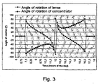
- solar radiation 1 is directed at the reflector 12 with a maximum degree of efficiency by using a lens 11 having a prism lens angle of 36° and a fixed exit angle of 36° in the direction of the lens surface 12b, with the entire device being oriented towards the south at an angle of 45°.
- the diagram of figure 3 shows the angles of rotation of the lens 11 (and the reflector 12) at the various positions of the sun in the sky on 21 June (in the Netherlands) for this lens configuration.
- the hours of the day in this case 21 June
- the specific angles of rotation of the lens 11 and the reflector 12 for each point in time are plotted on the vertical axis.
- Said angles of rotation are determined on the basis of the arithmetic model (or computing programme) that is carried out by the arithmetic unit 14a on the basis of the various positions of the sun Z in the sky on 21 June.
- the reflector surface 12b of the reflector 12 exhibits at least one concave curvature, for example a parabolic or hyperbolic curvature.
- the reflector 12 may be made of a plastic identical that of the lens 11, with the reflector 12 being coated with a reflective material, such as an aluminium or chromium coating.
- the reflector 12 may also be made of a metal, however, in which case the reflector surface 12a needs to be polished. Also in this case an efficiency loss must be taken into account in the reflection of the exiting solar radiation 1a-1a' on the reflector surface. However, there are coatings and other reflective materials available which reflect over 95% of the incident solar radiation.
- the reflector 12 is so constructed that the reflector surface 12a is only made up of one concave curvature, part of the incident light of the lens 11 will be lost after reflection by the reflector surface 12a.
- the area at the location of the target area 13 (the solar cell 13) will reflect insufficient solar radiation in the direction of the target area.
- the first concave curvature (indicated A in figure 6 ) merges into a second concave curvature (indicated B), which second concave curvature is clearly different in shape from the first concave curvature.
- the reflector surface 12a By configuring the reflector surface 12a as two concave curvatures merging into one another, a further efficiency improvement of the overall system is realised, because also the incident solar radiation 1" near the target area 13 can be captured yet after refraction and reflection (as solar radiation 1a") by the solar cell (photovoltaic cell) disposed in the target area 13 or by a solar cell (photovoltaic cell) disposed in another target area.
Landscapes
- Engineering & Computer Science (AREA)
- Chemical & Material Sciences (AREA)
- Life Sciences & Earth Sciences (AREA)
- Sustainable Development (AREA)
- Sustainable Energy (AREA)
- Thermal Sciences (AREA)
- Physics & Mathematics (AREA)
- Combustion & Propulsion (AREA)
- Mechanical Engineering (AREA)
- General Engineering & Computer Science (AREA)
- Photovoltaic Devices (AREA)
- Optical Elements Other Than Lenses (AREA)
- Mounting And Adjusting Of Optical Elements (AREA)
Claims (23)
- Vorrichtung (10) zur Umwandlung von Sonnenenergie mit einer Sonnenstrahlungs-Erfassungseinheit (11), welche zumindest eine Linse aufweist mit einer Eintrittsfläche (11a) für die einfallende Sonnenstrahlung und einer Austrittsfläche (11b) zur Abstrahlung der Sonnenstrahlung in gebrochener Form auf eine Sonnenstrahlungs-Bündelungseinheit (12), welche eine Reflektorfläche (12a) zur Reflexion der von der Austrittsfläche (11b) der Linse auf die Reflektorfläche (12a) einfallenden Sonnenstrahlung auf zumindest einen Zielbereich (13) der Sonnenstrahlungs-Bündelungseinheit (12) aufweist, dadurch gekennzeichnet, dass die Vorrichtung (10) Positionierungsmittel (14) aufweist zur Ausrichtung der Sonnenstrahlungs-Erfassungseinheit (11) und der Sonnenstrahlungs-Bündelungseinheit (12) zueinander in Abhängigkeit von einer Position der Sonne durch Rotation um zumindest eine Achse (11'), welche senkrecht zu einer von der Linse gebildeten Ebene ist.
- Vorrichtung (10) gemäß Anspruch 1, dadurch gekennzeichnet, dass die Rotationsachsen (11') der Sonnenstrahlungs-Erfassungseinheit (11) und der Sonnenstrahlungs-Bündelungseinheit (12) zwei verschiedene Achsen sind.
- Vorrichtung (10) gemäß Anspruch 1, dadurch gekennzeichnet, dass die Rotationsachsen (11') der Sonnenstrahlungs-Erfassungseinheit (11) und der Sonnenstrahlungs-Bündelungseinheit (12) zusammenfallen.
- Vorrichtung (10) nach einem oder mehreren der vorangehenden Ansprüche, dadurch gekennzeichnet, dass die Sonnenstrahlungs-Erfassungseinheit (11) und die Sonnenstrahlungs-Bündelungseinheit (12) durch Positionierungsmittel (14) in zueinander verschiedenen Ebenen ausrichtbar sind.
- Vorrichtung (10) nach einem oder mehreren der vorangehenden Ansprüche, dadurch gekennzeichnet, dass die Positionierungsmittel (14) zur gegenseitigen Ausrichtung der Sonnenstrahlungs-Erfassungseinheit (11) und der Sonnenstrahlungs-Bündelungseinheit (12) basierend auf der momentanen Position der Sonne am Himmel, der optischen Eigenschaften der Vorrichtung (10) sowie der Ausrichtung der Vorrichtung (10) ausgebildet sind.
- Vorrichtung (10) gemäß Anspruch 5, dadurch gekennzeichnet, dass die Positionierungsmittel (14) eine arithmetische Einheit (14a) aufweisen, welche zur Bestimmung der momentanen Position der Sonne am Himmel basierend auf der geografischen Position und der Ausrichtung auf der Erde sowie dem Tag und der Tageszeit ausgebildet ist.
- Vorrichtung (10) nach einem oder mehreren der vorangehenden Ansprüche, dadurch gekennzeichnet, dass die Vorrichtung (10) ein Gehäuse (10') aufweist, in welchem die Sonnenstrahlungs-Erfassungseinheit (11) und die Sonnenstrahlungs-Bündelungseinheit (12) drehbar gelagert sind.
- Vorrichtung (10) gemäß Anspruch 7, dadurch gekennzeichnet, dass im Gehäuse (10') eine Führung angebracht ist, welche als Rampe wirkt und über die die Sonnenstrahlungs-Erfassungseinheit (11) und die Sonnenstrahlungs-Bündelungseinheit (12) mit Hilfe der Positionierungsmittel (14) bewegbar sind.
- Vorrichtung (10) gemäß Anspruch 7 oder 8, dadurch gekennzeichnet, dass mehrere Rollen (15a, b) im Gehäuse (10') anbringbar sind, welche die Sonnenstrahlungs-Erfassungseinheit (11) und die Sonnenstrahlungs-Bündelungseinheit (12) tragen.
- Vorrichtung (10) gemäß Anspruch 9, dadurch gekennzeichnet, dass zumindest eine dieser Rollen (15a, b) mit Hilfe der Positionierungsmittel (14) antreibbar ist.
- Vorrichtung (10) gemäß Anspruch 10, dadurch gekennzeichnet, dass diese Rollen (15a, b) durch Motoren (16a, b) antreibbar sind, welche mit Hilfe der Positionierungsmittel (14) steuerbar sind.
- Vorrichtung (10) gemäß einem oder mehreren der Ansprüche 7 bis 11, dadurch gekennzeichnet, dass die Sonnenstrahlungs-Erfassungseinheit (11) und die Sonnenstrahlungs-Bündelungseinheit (12) innerhalb des Gehäuses (10') mittels einer Riemenübertragung, welche mit Hilfe der Positionierungsmittel (14) steuerbar ist, bewegbar sind.
- Vorrichtung (10) gemäß einem oder mehreren der vorangehenden Ansprüche, dadurch gekennzeichnet, dass die Eintrittsfläche (11a) der Linse eine ebene Fläche ist.
- Vorrichtung (10) gemäß einem oder mehreren der vorangehenden Ansprüche, dadurch gekennzeichnet, dass die Austrittsfläche (11b) der Linse als abgestufte Linse ausgebildet ist.
- Vorrichtung (10) gemäß Anspruch 14, dadurch gekennzeichnet, dass die Austrittsfläche (11b) der Linse als abgestufte, geradlinige Prismenlinse ausgebildet ist.
- Vorrichtung (10) gemäß Anspruch 14 oder 15, dadurch gekennzeichnet, dass der Prismenlinsenwinkel zwischen 15° und 50° liegt, insbesondere 36° ist.
- Vorrichtung (10) gemäß Anspruch 14, 15 oder 16, dadurch gekennzeichnet, dass die Sonnenstrahlungs-Erfassungseinheit (11) derart angeordnet ist, dass sie Sonnenstrahlung unter einem festgelegten Austrittswinkel im Bereich zwischen 15° und 55°, insbesondere unter einem Austrittswinkel von 36°, auf die Sonnenstrahlungs-Bündelungseinheit (12) abstrahlt.
- Vorrichtung (10) gemäß einem oder mehreren der vorangehenden Ansprüche, dadurch gekennzeichnet, dass die Vorrichtung (10) in einem Winkel gegenüber der Horizontalen positionierbar ist.
- Vorrichtung (10) gemäß Anspruch 18, dadurch gekennzeichnet, dass der genannte Winkel in Abhängigkeit des Breitengrads, an dem sich die Vorrichtung (10) befindet, einstellbar ist.
- Vorrichtung (10) gemäß einem oder mehreren der vorangehenden Ansprüche, dadurch gekennzeichnet, dass die Reflektorfläche (12a) zumindest eine konkave Krümmung aufweist.
- Vorrichtung (10) gemäß einem oder mehreren der vorangehenden Ansprüche, dadurch gekennzeichnet, dass die erste Hohlkrümmung der Reflektorfläche (12a) in eine zweite Hohlkrümmung, welche sich von der ersten Krümmung unterscheidet, an einem Punkt nahe dessen zugehörigen Zielbereichs (13) übergeht, wobei die zweite Krümmung gleichermaßen einen zugehörigen Zielbereich (13) bildet.
- Vorrichtung (10) gemäß einem oder mehreren der vorangehenden Ansprüche, dadurch gekennzeichnet, dass jeder Zielbereich (13) eine Sonnenstrahlungs-Konzentratorzelle aufweist.
- Vorrichtung (10) gemäß Anspruch 22, dadurch gekennzeichnet, dass die Sonnenstrahlungs-Konzentratorzelle am Rand des Reflektors angeordnet ist.
Priority Applications (3)
| Application Number | Priority Date | Filing Date | Title |
|---|---|---|---|
| SI200731020T SI2005074T1 (sl) | 2006-04-07 | 2007-04-05 | Naprava za pretvarjanje sončne energije |
| EP11177786A EP2416085A1 (de) | 2006-04-07 | 2007-04-05 | Vorrichtung zur umwandlung von sonnenenergie |
| PL07747277T PL2005074T3 (pl) | 2006-04-07 | 2007-04-05 | Urządzenie do przekształcania energii słonecznej |
Applications Claiming Priority (2)
| Application Number | Priority Date | Filing Date | Title |
|---|---|---|---|
| NL1031544A NL1031544C2 (nl) | 2006-04-07 | 2006-04-07 | Inrichting voor het omzetten van zonne-energie. |
| PCT/NL2007/000095 WO2007117136A1 (en) | 2006-04-07 | 2007-04-05 | Device for converting solar energy |
Related Child Applications (1)
| Application Number | Title | Priority Date | Filing Date |
|---|---|---|---|
| EP11177786.8 Division-Into | 2011-08-17 |
Publications (2)
| Publication Number | Publication Date |
|---|---|
| EP2005074A1 EP2005074A1 (de) | 2008-12-24 |
| EP2005074B1 true EP2005074B1 (de) | 2012-06-27 |
Family
ID=37441554
Family Applications (2)
| Application Number | Title | Priority Date | Filing Date |
|---|---|---|---|
| EP11177786A Ceased EP2416085A1 (de) | 2006-04-07 | 2007-04-05 | Vorrichtung zur umwandlung von sonnenenergie |
| EP07747277A Not-in-force EP2005074B1 (de) | 2006-04-07 | 2007-04-05 | Vorrichtung zur umwandlung von sonnenenergie |
Family Applications Before (1)
| Application Number | Title | Priority Date | Filing Date |
|---|---|---|---|
| EP11177786A Ceased EP2416085A1 (de) | 2006-04-07 | 2007-04-05 | Vorrichtung zur umwandlung von sonnenenergie |
Country Status (24)
| Country | Link |
|---|---|
| US (1) | US8944047B2 (de) |
| EP (2) | EP2416085A1 (de) |
| JP (1) | JP5250545B2 (de) |
| KR (1) | KR101443302B1 (de) |
| CN (1) | CN101466984B (de) |
| AU (1) | AU2007235726B2 (de) |
| BR (1) | BRPI0710673B1 (de) |
| CA (1) | CA2658047C (de) |
| DK (1) | DK2005074T3 (de) |
| EG (1) | EG24993A (de) |
| ES (1) | ES2390178T3 (de) |
| IL (1) | IL194536A (de) |
| MA (1) | MA30398B1 (de) |
| MX (1) | MX2008012901A (de) |
| MY (1) | MY157275A (de) |
| NL (1) | NL1031544C2 (de) |
| NZ (1) | NZ571804A (de) |
| PL (1) | PL2005074T3 (de) |
| PT (1) | PT2005074E (de) |
| RU (1) | RU2434184C2 (de) |
| SI (1) | SI2005074T1 (de) |
| TN (1) | TNSN08390A1 (de) |
| WO (1) | WO2007117136A1 (de) |
| ZA (1) | ZA200808602B (de) |
Families Citing this family (19)
| Publication number | Priority date | Publication date | Assignee | Title |
|---|---|---|---|---|
| EP2371004B1 (de) * | 2008-12-03 | 2015-07-29 | Sun Synchrony, Inc. | Sonnenenergiegewinnungssystem |
| US8592673B2 (en) * | 2009-05-04 | 2013-11-26 | The Boeing Company | Enclosed, off-axis solar concentrator |
| US20110088684A1 (en) * | 2009-10-16 | 2011-04-21 | Raja Singh Tuli | Solar Energy Concentrator |
| US8940999B1 (en) | 2009-12-07 | 2015-01-27 | The Boeing Company | Modular off-axis solar concentrator |
| CN102148277B (zh) * | 2010-02-05 | 2013-03-13 | 胜华科技股份有限公司 | 太阳能控光模块 |
| CN102158127A (zh) * | 2010-02-11 | 2011-08-17 | 群赞科技(深圳)有限公司 | 太阳能模组 |
| BR112012033459A2 (pt) * | 2010-07-01 | 2017-12-05 | Magna Int Inc | sistema coletor solar, e, método |
| US9054251B1 (en) | 2011-07-28 | 2015-06-09 | The Boeing Company | Solar collector array |
| KR101571926B1 (ko) | 2013-06-25 | 2015-12-07 | 김미애 | 평면거울들을 이용하여 균일하게 집광된 광빔 및 직접 접촉에 의한 냉각법을 이용한 태양광발전 장치 및 방법 |
| NL2011210C2 (nl) * | 2013-07-23 | 2015-01-26 | Suncycle B V | Inrichting voor het winnen van zonne-energie. |
| WO2015156666A1 (en) * | 2014-04-07 | 2015-10-15 | Suncycle B.V. | Solar energy conversion device and installation |
| NL2012583B1 (en) * | 2014-04-07 | 2016-07-15 | Suncycle B V | Helio-energic concentrator unit and device for gaining solar energy. |
| GB2540309B (en) * | 2014-05-22 | 2017-08-23 | Solar Cubed Holdings Llc | Electro-magnetic energy capturing system |
| CN106535962B (zh) * | 2014-06-10 | 2020-04-21 | 赛诺菲-安万特德国有限公司 | 用于确定与表面反射特征相关的信息的设备 |
| CN106288437B (zh) * | 2015-06-01 | 2018-11-20 | 博立码杰通讯(深圳)有限公司 | 多功能太阳能系统 |
| CN105577105B (zh) * | 2015-12-17 | 2018-09-14 | 广东五星太阳能股份有限公司 | 一种可固定安装的非对称聚光光伏光热系统 |
| CN106440411B (zh) * | 2016-10-13 | 2018-08-07 | 嘉兴恒日太阳能科技有限公司 | 一种高聚光蓄热式太阳能热水器 |
| GB201718715D0 (en) * | 2017-11-13 | 2017-12-27 | Pilkington Nederland B V | Multifunctional glazing unit |
| WO2021212422A1 (zh) * | 2020-04-23 | 2021-10-28 | 博立码杰通讯(深圳)有限公司 | 立式太阳能装置 |
Family Cites Families (27)
| Publication number | Priority date | Publication date | Assignee | Title |
|---|---|---|---|---|
| JPH07326214A (ja) | 1994-05-31 | 1995-12-12 | Sanyo Electric Co Ltd | 太陽光採光装置 |
| US3923039A (en) * | 1975-02-07 | 1975-12-02 | Gerald Falbel | Solar energy heating system |
| GB1529255A (en) | 1975-02-13 | 1978-10-18 | Unisearch Ltd | Device for concentrating solar radiation |
| US4836672A (en) * | 1980-05-02 | 1989-06-06 | Riverside Research Institute | Covert optical system for probing and inhibiting remote targets |
| JPS61180217A (ja) * | 1985-02-05 | 1986-08-12 | Kunishiro Kanagata Kogyo Kk | 太陽追尾装置 |
| JPH084146B2 (ja) * | 1987-04-13 | 1996-01-17 | 株式会社日立製作所 | 太陽光・熱ハイブリツド発電装置 |
| JP2653368B2 (ja) * | 1988-04-21 | 1997-09-17 | 工業技術院長 | 太陽熱調理器 |
| JPH04333810A (ja) | 1991-05-09 | 1992-11-20 | Sanyo Electric Co Ltd | 採光装置 |
| DE4126623A1 (de) * | 1991-08-12 | 1993-02-18 | Nikolaus Laing | Solarenergiewandler mit lichtleitelementen |
| JPH0618768A (ja) * | 1992-06-30 | 1994-01-28 | Nippon Polyester Kk | 太陽光採光装置 |
| JP2878549B2 (ja) * | 1993-03-18 | 1999-04-05 | 三菱レイヨン株式会社 | 採光装置 |
| US5374939A (en) * | 1993-07-07 | 1994-12-20 | Pullen V; William J. | Radiation gathering and focusing apparatus |
| US5934271A (en) * | 1994-07-19 | 1999-08-10 | Anutech Pty Limited | Large aperture solar collectors with improved stability |
| JPH08304692A (ja) * | 1995-05-12 | 1996-11-22 | Sanyo Electric Co Ltd | 太陽光採光装置 |
| RU2121632C1 (ru) * | 1997-03-13 | 1998-11-10 | Тверьянович Эдуард Владимирович | Устройство, концентрирующее солнечное излучение |
| WO2001059361A1 (en) * | 2000-02-14 | 2001-08-16 | The University Of British Columbia | Concentrating heliostat for solar lighting applications |
| IT1318222B1 (it) | 2000-07-21 | 2003-07-28 | Iguzzini Illuminazione Srl | Sistema di teletrasporto di luce naturale |
| JP2002081760A (ja) * | 2000-09-08 | 2002-03-22 | Mitsui Eng & Shipbuild Co Ltd | 太陽エネルギー利用システム |
| JP2003322419A (ja) | 2002-04-30 | 2003-11-14 | L C Chen Leon | 住宅用電力発電システムの太陽光複合集束機 |
| US6881893B1 (en) * | 2002-06-11 | 2005-04-19 | David M. Cobert | Solar energy collection system |
| US6818818B2 (en) * | 2002-08-13 | 2004-11-16 | Esmond T. Goei | Concentrating solar energy receiver |
| US6958868B1 (en) * | 2004-03-29 | 2005-10-25 | John George Pender | Motion-free tracking solar concentrator |
| ITRM20050635A1 (it) * | 2005-12-19 | 2007-06-20 | Eric S R L | Dispositivo e impianto fotovoltaico a concentrazione selettiva. |
| US20090000612A1 (en) * | 2007-05-04 | 2009-01-01 | Hines Braden E | Apparatuses and methods for shaping reflective surfaces of optical concentrators |
| US20100175685A1 (en) * | 2008-07-14 | 2010-07-15 | Robert Owen Campbell | Advanced Tracking Concentrator Employing Rotating Input Arrangement and Method |
| US20100006088A1 (en) * | 2008-07-14 | 2010-01-14 | Robert Owen Campbell | Tracking Concentrator Employing Inverted Off-Axis Optics and Method |
| US9182470B2 (en) * | 2009-11-17 | 2015-11-10 | Cogentrix Development Holdings, Llc | Inclinometer for a solar array and associated systems, methods, and computer program products |
-
2006
- 2006-04-07 NL NL1031544A patent/NL1031544C2/nl not_active IP Right Cessation
-
2007
- 2007-04-05 PT PT07747277T patent/PT2005074E/pt unknown
- 2007-04-05 BR BRPI0710673A patent/BRPI0710673B1/pt not_active IP Right Cessation
- 2007-04-05 DK DK07747277.7T patent/DK2005074T3/da active
- 2007-04-05 EP EP11177786A patent/EP2416085A1/de not_active Ceased
- 2007-04-05 AU AU2007235726A patent/AU2007235726B2/en not_active Ceased
- 2007-04-05 KR KR1020087026324A patent/KR101443302B1/ko not_active Expired - Fee Related
- 2007-04-05 WO PCT/NL2007/000095 patent/WO2007117136A1/en not_active Ceased
- 2007-04-05 MY MYPI20083980A patent/MY157275A/en unknown
- 2007-04-05 NZ NZ571804A patent/NZ571804A/en not_active IP Right Cessation
- 2007-04-05 MX MX2008012901A patent/MX2008012901A/es active IP Right Grant
- 2007-04-05 RU RU2008144138/06A patent/RU2434184C2/ru not_active IP Right Cessation
- 2007-04-05 ES ES07747277T patent/ES2390178T3/es active Active
- 2007-04-05 EP EP07747277A patent/EP2005074B1/de not_active Not-in-force
- 2007-04-05 PL PL07747277T patent/PL2005074T3/pl unknown
- 2007-04-05 CN CN2007800206002A patent/CN101466984B/zh not_active Expired - Fee Related
- 2007-04-05 US US12/296,391 patent/US8944047B2/en not_active Expired - Fee Related
- 2007-04-05 CA CA2658047A patent/CA2658047C/en not_active Expired - Fee Related
- 2007-04-05 JP JP2009504138A patent/JP5250545B2/ja not_active Expired - Fee Related
- 2007-04-05 SI SI200731020T patent/SI2005074T1/sl unknown
-
2008
- 2008-10-05 IL IL194536A patent/IL194536A/en not_active IP Right Cessation
- 2008-10-07 TN TNP2008000390A patent/TNSN08390A1/en unknown
- 2008-10-07 EG EG2008101645A patent/EG24993A/xx active
- 2008-10-08 ZA ZA200808602A patent/ZA200808602B/xx unknown
- 2008-11-04 MA MA31355A patent/MA30398B1/fr unknown
Also Published As
Similar Documents
| Publication | Publication Date | Title |
|---|---|---|
| EP2005074B1 (de) | Vorrichtung zur umwandlung von sonnenenergie | |
| US6691701B1 (en) | Modular solar radiation collection and distribution system | |
| US20100224231A1 (en) | Photovoltaic Module Utilizing Beam Steering and a Fixed Concentrator | |
| JP5337961B2 (ja) | 太陽追尾モジュール装置 | |
| EP2221552A2 (de) | Drehbare trogförmige Reflektoranordnung mit einem soliden optischen Element zur Erzeugung von Solarenergie | |
| WO2009063416A2 (en) | Thin and efficient collecting optics for solar system | |
| EP4026173B1 (de) | Fotovoltaisches solarkollektorsystem und natürliche beleuchtungsvorrichtung für gebäudeintegration | |
| US20100206379A1 (en) | Rotational Trough Reflector Array With Solid Optical Element For Solar-Electricity Generation | |
| US20240387761A1 (en) | Photovoltaic solar collection system and natural illumination apparatus for building integration | |
| US20060249143A1 (en) | Reflecting photonic concentrator | |
| RU2225965C1 (ru) | Солнечный модуль с концентратором | |
| RU2206837C2 (ru) | Солнечный модуль с концентратором (варианты) | |
| JP2003028514A (ja) | 太陽放射集中システム及び太陽放射の集中方法 | |
| WO2005088209A1 (en) | Modular solar radiation collection-distribution system | |
| WO2018023836A1 (zh) | 一种太阳能聚光器 | |
| US20100206357A1 (en) | Two-Part Solar Energy Collection System With Replaceable Solar Collector Component | |
| WO2018023835A1 (zh) | 一种太阳能收集系统和收集方法 | |
| CZ2021289A3 (cs) | Solární panel s reflexní postranní stěnou |
Legal Events
| Date | Code | Title | Description |
|---|---|---|---|
| PUAI | Public reference made under article 153(3) epc to a published international application that has entered the european phase |
Free format text: ORIGINAL CODE: 0009012 |
|
| 17P | Request for examination filed |
Effective date: 20081009 |
|
| AK | Designated contracting states |
Kind code of ref document: A1 Designated state(s): AT BE BG CH CY CZ DE DK EE ES FI FR GB GR HU IE IS IT LI LT LU LV MC MT NL PL PT RO SE SI SK TR |
|
| GRAP | Despatch of communication of intention to grant a patent |
Free format text: ORIGINAL CODE: EPIDOSNIGR1 |
|
| DAX | Request for extension of the european patent (deleted) | ||
| GRAS | Grant fee paid |
Free format text: ORIGINAL CODE: EPIDOSNIGR3 |
|
| RAP1 | Party data changed (applicant data changed or rights of an application transferred) |
Owner name: SUNCYCLE B.V. |
|
| GRAJ | Information related to disapproval of communication of intention to grant by the applicant or resumption of examination proceedings by the epo deleted |
Free format text: ORIGINAL CODE: EPIDOSDIGR1 |
|
| 17Q | First examination report despatched |
Effective date: 20100506 |
|
| GRAP | Despatch of communication of intention to grant a patent |
Free format text: ORIGINAL CODE: EPIDOSNIGR1 |
|
| GRAS | Grant fee paid |
Free format text: ORIGINAL CODE: EPIDOSNIGR3 |
|
| GRAA | (expected) grant |
Free format text: ORIGINAL CODE: 0009210 |
|
| AK | Designated contracting states |
Kind code of ref document: B1 Designated state(s): AT BE BG CH CY CZ DE DK EE ES FI FR GB GR HU IE IS IT LI LT LU LV MC MT NL PL PT RO SE SI SK TR |
|
| REG | Reference to a national code |
Ref country code: GB Ref legal event code: FG4D |
|
| REG | Reference to a national code |
Ref country code: CH Ref legal event code: EP |
|
| REG | Reference to a national code |
Ref country code: AT Ref legal event code: REF Ref document number: 564454 Country of ref document: AT Kind code of ref document: T Effective date: 20120715 |
|
| REG | Reference to a national code |
Ref country code: IE Ref legal event code: FG4D |
|
| REG | Reference to a national code |
Ref country code: DE Ref legal event code: R096 Ref document number: 602007023621 Country of ref document: DE Effective date: 20120823 |
|
| REG | Reference to a national code |
Ref country code: NL Ref legal event code: T3 |
|
| REG | Reference to a national code |
Ref country code: RO Ref legal event code: EPE |
|
| REG | Reference to a national code |
Ref country code: PT Ref legal event code: SC4A Free format text: AVAILABILITY OF NATIONAL TRANSLATION Effective date: 20120920 |
|
| REG | Reference to a national code |
Ref country code: DK Ref legal event code: T3 |
|
| REG | Reference to a national code |
Ref country code: SE Ref legal event code: TRGR |
|
| REG | Reference to a national code |
Ref country code: GR Ref legal event code: EP Ref document number: 20120402111 Country of ref document: GR Effective date: 20120915 |
|
| PG25 | Lapsed in a contracting state [announced via postgrant information from national office to epo] |
Ref country code: FI Free format text: LAPSE BECAUSE OF FAILURE TO SUBMIT A TRANSLATION OF THE DESCRIPTION OR TO PAY THE FEE WITHIN THE PRESCRIBED TIME-LIMIT Effective date: 20120627 Ref country code: LT Free format text: LAPSE BECAUSE OF FAILURE TO SUBMIT A TRANSLATION OF THE DESCRIPTION OR TO PAY THE FEE WITHIN THE PRESCRIBED TIME-LIMIT Effective date: 20120627 |
|
| REG | Reference to a national code |
Ref country code: ES Ref legal event code: FG2A Ref document number: 2390178 Country of ref document: ES Kind code of ref document: T3 Effective date: 20121107 |
|
| REG | Reference to a national code |
Ref country code: LT Ref legal event code: MG4D Effective date: 20120627 |
|
| PG25 | Lapsed in a contracting state [announced via postgrant information from national office to epo] |
Ref country code: LV Free format text: LAPSE BECAUSE OF FAILURE TO SUBMIT A TRANSLATION OF THE DESCRIPTION OR TO PAY THE FEE WITHIN THE PRESCRIBED TIME-LIMIT Effective date: 20120627 |
|
| REG | Reference to a national code |
Ref country code: PL Ref legal event code: T3 |
|
| REG | Reference to a national code |
Ref country code: SK Ref legal event code: T3 Ref document number: E 12725 Country of ref document: SK |
|
| PG25 | Lapsed in a contracting state [announced via postgrant information from national office to epo] |
Ref country code: IS Free format text: LAPSE BECAUSE OF FAILURE TO SUBMIT A TRANSLATION OF THE DESCRIPTION OR TO PAY THE FEE WITHIN THE PRESCRIBED TIME-LIMIT Effective date: 20121027 Ref country code: EE Free format text: LAPSE BECAUSE OF FAILURE TO SUBMIT A TRANSLATION OF THE DESCRIPTION OR TO PAY THE FEE WITHIN THE PRESCRIBED TIME-LIMIT Effective date: 20120627 Ref country code: CY Free format text: LAPSE BECAUSE OF FAILURE TO SUBMIT A TRANSLATION OF THE DESCRIPTION OR TO PAY THE FEE WITHIN THE PRESCRIBED TIME-LIMIT Effective date: 20120627 |
|
| PLBE | No opposition filed within time limit |
Free format text: ORIGINAL CODE: 0009261 |
|
| STAA | Information on the status of an ep patent application or granted ep patent |
Free format text: STATUS: NO OPPOSITION FILED WITHIN TIME LIMIT |
|
| 26N | No opposition filed |
Effective date: 20130328 |
|
| REG | Reference to a national code |
Ref country code: DE Ref legal event code: R097 Ref document number: 602007023621 Country of ref document: DE Effective date: 20130328 |
|
| REG | Reference to a national code |
Ref country code: HU Ref legal event code: AG4A Ref document number: E016138 Country of ref document: HU |
|
| PG25 | Lapsed in a contracting state [announced via postgrant information from national office to epo] |
Ref country code: MC Free format text: LAPSE BECAUSE OF FAILURE TO SUBMIT A TRANSLATION OF THE DESCRIPTION OR TO PAY THE FEE WITHIN THE PRESCRIBED TIME-LIMIT Effective date: 20120627 |
|
| PGFP | Annual fee paid to national office [announced via postgrant information from national office to epo] |
Ref country code: LU Payment date: 20140507 Year of fee payment: 8 |
|
| PG25 | Lapsed in a contracting state [announced via postgrant information from national office to epo] |
Ref country code: MT Free format text: LAPSE BECAUSE OF FAILURE TO SUBMIT A TRANSLATION OF THE DESCRIPTION OR TO PAY THE FEE WITHIN THE PRESCRIBED TIME-LIMIT Effective date: 20120627 |
|
| PG25 | Lapsed in a contracting state [announced via postgrant information from national office to epo] |
Ref country code: LU Free format text: LAPSE BECAUSE OF NON-PAYMENT OF DUE FEES Effective date: 20150405 |
|
| REG | Reference to a national code |
Ref country code: FR Ref legal event code: PLFP Year of fee payment: 10 |
|
| PGFP | Annual fee paid to national office [announced via postgrant information from national office to epo] |
Ref country code: RO Payment date: 20160331 Year of fee payment: 10 |
|
| PGFP | Annual fee paid to national office [announced via postgrant information from national office to epo] |
Ref country code: CZ Payment date: 20160404 Year of fee payment: 10 Ref country code: BG Payment date: 20160414 Year of fee payment: 10 Ref country code: IE Payment date: 20160421 Year of fee payment: 10 |
|
| PGFP | Annual fee paid to national office [announced via postgrant information from national office to epo] |
Ref country code: SE Payment date: 20160420 Year of fee payment: 10 Ref country code: HU Payment date: 20160420 Year of fee payment: 10 Ref country code: PL Payment date: 20160404 Year of fee payment: 10 Ref country code: SK Payment date: 20160404 Year of fee payment: 10 Ref country code: DK Payment date: 20160420 Year of fee payment: 10 Ref country code: SI Payment date: 20160330 Year of fee payment: 10 |
|
| REG | Reference to a national code |
Ref country code: FR Ref legal event code: PLFP Year of fee payment: 11 |
|
| PGFP | Annual fee paid to national office [announced via postgrant information from national office to epo] |
Ref country code: GB Payment date: 20170419 Year of fee payment: 11 |
|
| PGFP | Annual fee paid to national office [announced via postgrant information from national office to epo] |
Ref country code: PT Payment date: 20170403 Year of fee payment: 11 Ref country code: BE Payment date: 20170426 Year of fee payment: 11 Ref country code: AT Payment date: 20170420 Year of fee payment: 11 |
|
| PG25 | Lapsed in a contracting state [announced via postgrant information from national office to epo] |
Ref country code: CZ Free format text: LAPSE BECAUSE OF NON-PAYMENT OF DUE FEES Effective date: 20170405 |
|
| REG | Reference to a national code |
Ref country code: DK Ref legal event code: EBP Effective date: 20170430 |
|
| REG | Reference to a national code |
Ref country code: DE Ref legal event code: R079 Ref document number: 602007023621 Country of ref document: DE Free format text: PREVIOUS MAIN CLASS: F24J0002060000 Ipc: F24S0023000000 |
|
| REG | Reference to a national code |
Ref country code: SK Ref legal event code: MM4A Ref document number: E 12725 Country of ref document: SK Effective date: 20170405 |
|
| REG | Reference to a national code |
Ref country code: IE Ref legal event code: MM4A |
|
| PG25 | Lapsed in a contracting state [announced via postgrant information from national office to epo] |
Ref country code: SK Free format text: LAPSE BECAUSE OF NON-PAYMENT OF DUE FEES Effective date: 20170405 Ref country code: HU Free format text: LAPSE BECAUSE OF NON-PAYMENT OF DUE FEES Effective date: 20170406 Ref country code: RO Free format text: LAPSE BECAUSE OF NON-PAYMENT OF DUE FEES Effective date: 20170405 |
|
| PG25 | Lapsed in a contracting state [announced via postgrant information from national office to epo] |
Ref country code: SI Free format text: LAPSE BECAUSE OF NON-PAYMENT OF DUE FEES Effective date: 20170406 Ref country code: SE Free format text: LAPSE BECAUSE OF NON-PAYMENT OF DUE FEES Effective date: 20170406 |
|
| REG | Reference to a national code |
Ref country code: SI Ref legal event code: KO00 Effective date: 20180111 |
|
| REG | Reference to a national code |
Ref country code: FR Ref legal event code: PLFP Year of fee payment: 12 |
|
| PG25 | Lapsed in a contracting state [announced via postgrant information from national office to epo] |
Ref country code: IE Free format text: LAPSE BECAUSE OF NON-PAYMENT OF DUE FEES Effective date: 20170405 Ref country code: DK Free format text: LAPSE BECAUSE OF NON-PAYMENT OF DUE FEES Effective date: 20170430 |
|
| PGFP | Annual fee paid to national office [announced via postgrant information from national office to epo] |
Ref country code: TR Payment date: 20180330 Year of fee payment: 12 |
|
| PGFP | Annual fee paid to national office [announced via postgrant information from national office to epo] |
Ref country code: CH Payment date: 20180419 Year of fee payment: 12 Ref country code: DE Payment date: 20180420 Year of fee payment: 12 Ref country code: ES Payment date: 20180525 Year of fee payment: 12 |
|
| PGFP | Annual fee paid to national office [announced via postgrant information from national office to epo] |
Ref country code: IT Payment date: 20180423 Year of fee payment: 12 Ref country code: NL Payment date: 20180426 Year of fee payment: 12 Ref country code: FR Payment date: 20180420 Year of fee payment: 12 Ref country code: GR Payment date: 20180413 Year of fee payment: 12 |
|
| PG25 | Lapsed in a contracting state [announced via postgrant information from national office to epo] |
Ref country code: PL Free format text: LAPSE BECAUSE OF NON-PAYMENT OF DUE FEES Effective date: 20170405 |
|
| REG | Reference to a national code |
Ref country code: AT Ref legal event code: MM01 Ref document number: 564454 Country of ref document: AT Kind code of ref document: T Effective date: 20180405 |
|
| REG | Reference to a national code |
Ref country code: BE Ref legal event code: MM Effective date: 20180430 |
|
| GBPC | Gb: european patent ceased through non-payment of renewal fee |
Effective date: 20180405 |
|
| PG25 | Lapsed in a contracting state [announced via postgrant information from national office to epo] |
Ref country code: PT Free format text: LAPSE BECAUSE OF NON-PAYMENT OF DUE FEES Effective date: 20181008 Ref country code: AT Free format text: LAPSE BECAUSE OF NON-PAYMENT OF DUE FEES Effective date: 20180405 Ref country code: BG Free format text: LAPSE BECAUSE OF NON-PAYMENT OF DUE FEES Effective date: 20171105 |
|
| PG25 | Lapsed in a contracting state [announced via postgrant information from national office to epo] |
Ref country code: GB Free format text: LAPSE BECAUSE OF NON-PAYMENT OF DUE FEES Effective date: 20180405 Ref country code: BE Free format text: LAPSE BECAUSE OF NON-PAYMENT OF DUE FEES Effective date: 20180430 |
|
| REG | Reference to a national code |
Ref country code: DE Ref legal event code: R119 Ref document number: 602007023621 Country of ref document: DE |
|
| REG | Reference to a national code |
Ref country code: CH Ref legal event code: PL |
|
| REG | Reference to a national code |
Ref country code: NL Ref legal event code: MM Effective date: 20190501 |
|
| PG25 | Lapsed in a contracting state [announced via postgrant information from national office to epo] |
Ref country code: DE Free format text: LAPSE BECAUSE OF NON-PAYMENT OF DUE FEES Effective date: 20191101 Ref country code: CH Free format text: LAPSE BECAUSE OF NON-PAYMENT OF DUE FEES Effective date: 20190430 Ref country code: LI Free format text: LAPSE BECAUSE OF NON-PAYMENT OF DUE FEES Effective date: 20190430 Ref country code: NL Free format text: LAPSE BECAUSE OF NON-PAYMENT OF DUE FEES Effective date: 20190501 |
|
| PG25 | Lapsed in a contracting state [announced via postgrant information from national office to epo] |
Ref country code: GR Free format text: LAPSE BECAUSE OF NON-PAYMENT OF DUE FEES Effective date: 20191105 Ref country code: FR Free format text: LAPSE BECAUSE OF NON-PAYMENT OF DUE FEES Effective date: 20190430 |
|
| PG25 | Lapsed in a contracting state [announced via postgrant information from national office to epo] |
Ref country code: IT Free format text: LAPSE BECAUSE OF NON-PAYMENT OF DUE FEES Effective date: 20190405 |
|
| REG | Reference to a national code |
Ref country code: ES Ref legal event code: FD2A Effective date: 20200828 |
|
| PG25 | Lapsed in a contracting state [announced via postgrant information from national office to epo] |
Ref country code: ES Free format text: LAPSE BECAUSE OF NON-PAYMENT OF DUE FEES Effective date: 20190406 |
|
| PG25 | Lapsed in a contracting state [announced via postgrant information from national office to epo] |
Ref country code: TR Free format text: LAPSE BECAUSE OF NON-PAYMENT OF DUE FEES Effective date: 20190405 |