EP2004986B1 - Kraftstoffeinspritzsystem - Google Patents
Kraftstoffeinspritzsystem Download PDFInfo
- Publication number
- EP2004986B1 EP2004986B1 EP07716015A EP07716015A EP2004986B1 EP 2004986 B1 EP2004986 B1 EP 2004986B1 EP 07716015 A EP07716015 A EP 07716015A EP 07716015 A EP07716015 A EP 07716015A EP 2004986 B1 EP2004986 B1 EP 2004986B1
- Authority
- EP
- European Patent Office
- Prior art keywords
- valve
- nozzle
- pressure
- outlet
- fuel
- Prior art date
- Legal status (The legal status is an assumption and is not a legal conclusion. Google has not performed a legal analysis and makes no representation as to the accuracy of the status listed.)
- Active
Links
Images


Classifications
-
- F—MECHANICAL ENGINEERING; LIGHTING; HEATING; WEAPONS; BLASTING
- F02—COMBUSTION ENGINES; HOT-GAS OR COMBUSTION-PRODUCT ENGINE PLANTS
- F02M—SUPPLYING COMBUSTION ENGINES IN GENERAL WITH COMBUSTIBLE MIXTURES OR CONSTITUENTS THEREOF
- F02M63/00—Other fuel-injection apparatus having pertinent characteristics not provided for in groups F02M39/00 - F02M57/00 or F02M67/00; Details, component parts, or accessories of fuel-injection apparatus, not provided for in, or of interest apart from, the apparatus of groups F02M39/00 - F02M61/00 or F02M67/00; Combination of fuel pump with other devices, e.g. lubricating oil pump
- F02M63/0003—Fuel-injection apparatus having a cyclically-operated valve for connecting a pressure source, e.g. constant pressure pump or accumulator, to an injection valve held closed mechanically, e.g. by springs, and automatically opened by fuel pressure
- F02M63/0005—Fuel-injection apparatus having a cyclically-operated valve for connecting a pressure source, e.g. constant pressure pump or accumulator, to an injection valve held closed mechanically, e.g. by springs, and automatically opened by fuel pressure using valves actuated by fluid pressure
-
- F—MECHANICAL ENGINEERING; LIGHTING; HEATING; WEAPONS; BLASTING
- F02—COMBUSTION ENGINES; HOT-GAS OR COMBUSTION-PRODUCT ENGINE PLANTS
- F02M—SUPPLYING COMBUSTION ENGINES IN GENERAL WITH COMBUSTIBLE MIXTURES OR CONSTITUENTS THEREOF
- F02M63/00—Other fuel-injection apparatus having pertinent characteristics not provided for in groups F02M39/00 - F02M57/00 or F02M67/00; Details, component parts, or accessories of fuel-injection apparatus, not provided for in, or of interest apart from, the apparatus of groups F02M39/00 - F02M61/00 or F02M67/00; Combination of fuel pump with other devices, e.g. lubricating oil pump
- F02M63/0003—Fuel-injection apparatus having a cyclically-operated valve for connecting a pressure source, e.g. constant pressure pump or accumulator, to an injection valve held closed mechanically, e.g. by springs, and automatically opened by fuel pressure
- F02M63/0007—Fuel-injection apparatus having a cyclically-operated valve for connecting a pressure source, e.g. constant pressure pump or accumulator, to an injection valve held closed mechanically, e.g. by springs, and automatically opened by fuel pressure using electrically actuated valves
Definitions
- the present invention relates to a fuel injection system for an internal combustion engine.
- the present invention concerns fuel injection systems of internal combustion engines, in particular systems for injection of fuel directly into combustion cylinders of compression ignition engines.
- it concerns fuel injection systems featuring a control valve for pressure relief in the nozzle of the injector.
- Such solutions are typically applied in common rail injection systems for preventing a leakage of fuel through the closed nozzle, which is otherwise difficult to avoid when using low viscosity fuels such as DME.
- FIG.1 An example of such a prior art system is shown in Fig.1 .
- the total number of the isolating valves is kept low.
- Another disadvantage is a relatively big dead volume of the isolating valve which is added to the high-pressure volume confined between the control valve 10 and the nozzle 11. The bigger that dead volume, the bigger is the control leakage and the worse controllability due to delays associated with building up and relieving pressure in that volume.
- the number of connection ports in the injector is reduced from three to two, but at the expense of the increased number of the automatic isolating valves, two per injector.
- the present invention is intended to improve reliability, reduce cost, improve controllability and reduce leakage of the prior art systems.
- NOP nozzle opening pressure
- a pressure regulator installed between the spring chambers of the set of injectors and the return conduit, as shown in Fig.3 , which again implies three connection ports per injector.
- NOP control port By providing a relatively large volume of the nozzle spring chamber, it is in principle possible to eliminate the NOP control port and have a pressure regulator connected between the return line and the return conduit as shown in Fig.4 , but in that case the NOP control is complicated by differences in the leakages along the nozzle needle guides of different injector samples, the influence of the residual pressure on the nozzle closing pressure and leakage past the closed nozzle, and is besides relatively slow-acting.
- the present invention also offers means of improving the NOP control in such fuel injection systems.
- the objects of the present invention are to provide a fuel injection system with reduced complexity, improved energy efficiency and better controllability of injection rate.
- the fuel injection system incorporates a fuel tank, a feed pump and associated components forming a low-pressure system, and a high-pressure pump delivering fuel under pressure into a common rail, which supplies pressurised fuel to all injectors of a multi-cylinder engine.
- a first automatic isolating valve is installed between the common rail and the injector, which incorporates a three-way electrically operated pilot valve that controls a hydraulically operated valve positioned between the common rail and a nozzle, and an electrically operated, two-way, normally open spill valve positioned between the outlet of the hydraulically operated valve and a return line.
- the nozzle has a needle that is biased by a return spring towards closing the nozzle.
- the return spring is installed in a spring chamber which, if pressurised, can assist the spring in biasing the needle towards nozzle closing.
- the spring chamber, the outlet of the pilot valve and the outlet of the spill valve are connected to an injector return line.
- the return lines of the injectors are joined together into a single return conduit, which is connected via a second automatic isolating valve to the low-pressure system.
- a restriction is placed between the return line of each injector and the return conduit.
- Another advantage of this is a simplified design, improved reliability and reduced cost of the fuel injection system, because the injector can have only two connection ports, high pressure and return, and at the same time the total number of automatic isolating valves can be kept to a minimum equal to the number of injectors plus one.
- the total number of the automatic isolating valves should be double the number of injectors if the latter have two ports. Otherwise, if a common automatic isolating valve is used in the return conduit of a prior art system, the number of ports on the injector must be increased to three.
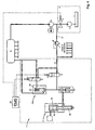
- the fuel injection system incorporates a fuel tank 1, a feed pump 2, an isolating valve 3 and other associated components (not shown) forming a low-pressure system 4, and a high-pressure pump 5 delivering fuel under pressure into a common rail 6, which supplies pressurised fuel to all injectors 7 of a multi-cylinder engine (not shown).
- a first automatic isolating valve 8 is installed between the common rail 6 and the injector 7, which latter one incorporates a three-way electrically operated pilot valve 9 that controls a hydraulically operated valve 10 positioned between the common rail and a nozzle 11, and an electrically operated, two-way, normally open spill valve 12 positioned between the outlet of the hydraulically operated valve 10 and a return line 13.
- the nozzle 11 has a needle 14 that is biased by a return spring 15 towards closing the nozzle.
- the return spring is installed in a spring chamber 16 which, if pressurised, can assist the spring 15 in biasing the needle 14 towards nozzle closing.
- the spring chamber 16, the outlet of the pilot valve 9 and the outlet of the spill valve 12 are connected to the return line 13.
- the return lines 13 of the injectors are joined together into a common return conduit 17, which is connected via a second automatic isolating valve 18 to the low-pressure system 4.
- a restriction 19 is placed between the return line 13 of each injector and the return conduit 17.
- An engine management system (EMS) 20 controls the valves 9 and 12.
- the hydraulically operated valve 10 preferably has a precision-matched stem and forms an outlet chamber 22 and a control chamber 23, and is preferably biased towards its closed position by a resilient means 24.
- the control chamber 23 of the valve 10 can be connected by the three-way pilot valve 9 to either the common rail 6 or the return line 13, depending on commands from the EMS 20.
- the automatic isolating valves 8, 18 are designed such that, once the valve is open, the area of the valve that is exposed to the pressure of the fuel is sufficiently big to hold the valve open against the force of the valve's return spring when the pressure in the valve is anywhere from slightly below the feed pressure in the system or above that level. In case of engine being stopped and the feed pressure falling below a predetermined level, the automatic isolating valve closes and the area of the valve exposed to the pressure upstream of the valve becomes relatively small, such that a pressure above the feed pressure level is required to re-open the automatic isolating valve.
- the design of such a valve is known in the art and is disclosed, for example, in the US Patent No. 6,189,517 B1 .
- the fuel injection system works as follows: In a no-injection state but with the engine running, there is feed pressure downstream of the low-pressure system 4 and in the return conduit 17; the high-pressure pump pressurizes the fuel to a certain level and maintains that level in the common rail 6.
- the valves 9 and 12 are not activated by the EMS 20.
- the three-way pilot valve 9, in its de-activated position connects the common rail 6 to the control chamber 23 of the hydraulically operated valve 10.
- the pressure from the common rail combined with the force of the resilient means 24, holds the valve 10 in its closed position.
- the spill valve 12 is open, connecting the outlet of the hydraulically operated valve 10 to the return line 13 and the return conduit 17 via the restriction 19.
- the automatic isolating valves 8, 18 are open, and pressure in the nozzle 11 equals pressure in the return conduit 17.
- the nozzle is closed by the needle return spring 15 and the force of the pressure in the spring chamber 16 acting on the needle 14.
- the EMS applies a control current to the pilot valve 9, which disconnects the control chamber 23 of the hydraulically operated valve 10 from the common rail 6 and connects it to the outlet of spill valve 12 and the inlet of the restriction 19.
- the pressure in the control chamber 23 falls and allows the common rail pressure acting on the valve from the outlet chamber 22 to open the valve 10 against the force of the resilient means 24.
- the EMS closes the spill valve 12 at about the same time, so that the fuel pressure at the inlet of the restriction 19, and therefore in the return line 13 and the spring chamber 16 of the nozzle 11, does not build up whilst it increases on the inlet side of the nozzle 11 and eventually opens the nozzle by lifting the needle 14 against the low pressure in the spring chamber 16 and the force of the return spring 15.
- the EMS applies control current to the spill valve 12 after a delay, allowing the fuel from the common rail to flow past the opening hydraulically operated valve 10 to build up pressure on both sides of the closed needle 14. When this pressure reaches a required level, the spill valve 12 gets closed by the EMS and the pressure on the back of the needle 14 is relieved to the return line 13, such that nozzle 11 opens and injection begins.
- the EMS de-activates the pilot valve 9, which then disconnects the control chamber 23 from the return line 13 and connects it back to the common rail.
- the pressure in the control chamber 23 rises and, together with the resilient means 24, forces the valve 10 down towards the closed position.
- the fuel continues to be injected from the open nozzle and the pressure in the nozzle falls until the return spring 15 moves the needle 14 down and closes the nozzle.
- the EMS de-activates and opens the spill valve 12 to relieve the nozzle of the residual pressure which can otherwise leak past the closed nozzle into the engine.
- the system returns to its initial position as depicted by Fig. 1 .
- the EMS opens the spill valve 12 before the nozzle 11 has been closed and while there is still a relatively high pressure upstream of the nozzle. This, because of the restriction 19, provides a surge of pressure in the return line 13 and in the spring chamber 16, which assists in closing the nozzle quicker.
- the pressure in the common rail can be reduced by, for example, activating the pilot valve 9 while keeping the spill valve 12 open, which essentially drains the fuel back to the low-pressure system.
- the valves 8, 18 in this case separate the relatively large volumes of common rail and associated components that may contain any residual pressure, from the nozzles.
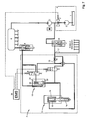
- Fig. 6 an alternative embodiment of the invention is shown, in which the outlet of the pilot valve 9 is connected to the return conduit 17, bypassing the restriction 19. This allows making the control of the hydraulically operated valve 10 less dependent of the NOP control.
- Fig. 7 another alternative embodiment of the invention is shown, in which the outlet of the spill valve 12 is connected to the return conduit 17 and the outlet of the pilot valve 9 is connected to the return line 13.
- the NOP is directly influenced by the operation of the pilot valve only.
Claims (5)
- Kraftstoffeinspritzsystem für einen Verbrennungsmotor, mit einem Motormanagementsystem (EMS) (20), einer mit einem Niederdruckkraftstoffsystem (4) verbundenen Rückführleitung (17) und einer gemeinsamen Verteilerleiste (6) zum Speichern und für eine Zufuhr eines mit relativ hohem Druck beaufschlagten Kraftstoffs zu Injektoren (7), wobei jeder der Injektoren eine Düse (11) zum Einspritzen von Kraftstoff in den Motor, ein zwischen der gemeinsamen Verteilerleiste (6) und der Düse (11) angebrachtes Ventil (10), und ein Überströmventil (12), das mit seinem Einlass mit dem Auslass des Ventils (10) und mit seinem Auslass mit der Rückführleitung (17) verbunden ist, aufweist, dadurch gekennzeichnet, dass ein erstes automatisches Absperrventil (8) zwischen der gemeinsamen Verteilerleiste (6) und dem Injektor (7) angebracht ist und ein zweites automatisches Absperrventil (18) in der Rückführleitung (17) zwischen dem Überströmventil (12) und dem Niedrigdruckkraftstoffsystem (4) angebracht ist.
- Kraftstoffeinspritzsystem nach Anspruch 1, dadurch gekennzeichnet, dass die Rückführleitung (17) für den Satz von Injektoren (7) eines Mehrzylindermotors gemeinsam ist.
- Kraftstoffeinspritzsystem nach einem der vorhergehenden Ansprüche,
dadurch gekennzeichnet, dass die Düse (11) eine Nadel (14) aufweist, die in Richtung des Schließens der Düse (11) durch eine Druckkraft in einer Federkammer (16) vorgespannt ist, und dass eine Rückführleitung (13) vorgesehen ist, die mit dem Auslass des Überströmventils (12) und dem Einlass einer Drossel (19) verbunden ist, wobei der Auslass der Drossel (19) mit der Rückführleitung (17) verbunden ist, wobei die Federkammer (16) mit der Rückführleitung (13) verbunden ist. - Kraftstoffeinspritzsystem nach Anspruch 3, dadurch gekennzeichnet, dass ein Steuerventil (9) vorgesehen ist, das zur Steuerung der Position des Ventils (10) durch die EMS betätigbar ist, wobei der Auslass des Steuerventils (9) mit der Rückführleitung (13) verbunden ist.
- Kraftstoffeinspritzsystem nach Anspruch 4, dadurch gekennzeichnet, dass der Auslass des Steuerventils (9) mit der Rückführleitung (17) verbunden ist.
Applications Claiming Priority (2)
| Application Number | Priority Date | Filing Date | Title |
|---|---|---|---|
| SE0600725 | 2006-03-30 | ||
| PCT/SE2007/000163 WO2007114750A1 (en) | 2006-03-30 | 2007-02-23 | Fuel injection system |
Publications (3)
| Publication Number | Publication Date |
|---|---|
| EP2004986A1 EP2004986A1 (de) | 2008-12-24 |
| EP2004986A4 EP2004986A4 (de) | 2011-02-02 |
| EP2004986B1 true EP2004986B1 (de) | 2012-01-18 |
Family
ID=38563932
Family Applications (1)
| Application Number | Title | Priority Date | Filing Date |
|---|---|---|---|
| EP07716015A Active EP2004986B1 (de) | 2006-03-30 | 2007-02-23 | Kraftstoffeinspritzsystem |
Country Status (7)
| Country | Link |
|---|---|
| US (1) | US7730876B2 (de) |
| EP (1) | EP2004986B1 (de) |
| JP (1) | JP5089679B2 (de) |
| CN (1) | CN101400886B (de) |
| AT (1) | ATE542046T1 (de) |
| BR (1) | BRPI0709255A2 (de) |
| WO (1) | WO2007114750A1 (de) |
Families Citing this family (5)
| Publication number | Priority date | Publication date | Assignee | Title |
|---|---|---|---|---|
| JP5075991B2 (ja) * | 2008-03-04 | 2012-11-21 | ボルボ ラストバグナー アーベー | 燃料噴射システム |
| WO2013117200A1 (en) * | 2012-02-07 | 2013-08-15 | Volvo Lastvagnar Ab | Fuel injection system |
| WO2015043611A1 (en) * | 2013-09-24 | 2015-04-02 | Volvo Truck Corporation | A fuel injection system for an internal combustion engine and a method of controlling fuel injection into an internal combustion engine |
| CN104847512B (zh) * | 2014-02-19 | 2019-09-06 | 卡特彼勒公司 | 用于共轨燃料喷射的控制模块 |
| US20220356859A1 (en) * | 2019-08-29 | 2022-11-10 | Volvo Truck Corporation | A fuel injection system |
Family Cites Families (9)
| Publication number | Priority date | Publication date | Assignee | Title |
|---|---|---|---|---|
| US4462368A (en) * | 1980-07-10 | 1984-07-31 | Diesel Kiki Company, Ltd. | Fuel injection system for internal combustion engine |
| DE19504849A1 (de) * | 1995-02-15 | 1996-08-22 | Bosch Gmbh Robert | Kraftstoffeinspritzeinrichtung für Brennkraftmaschinen |
| DE19939425B4 (de) * | 1999-08-20 | 2005-05-04 | Robert Bosch Gmbh | Kraftstoffeinspritzsystem für eine Brennkraftmaschine |
| DE10063545C1 (de) * | 2000-12-20 | 2002-08-01 | Bosch Gmbh Robert | Kraftstoffeinspritzeinrichtung |
| DE10132732A1 (de) * | 2001-07-05 | 2003-01-23 | Bosch Gmbh Robert | Kraftstoffeinspritzeinrichtung |
| DE10146745A1 (de) * | 2001-09-22 | 2003-04-10 | Bosch Gmbh Robert | Kraftstoffeinspritzeinrichtung für eine Brennkraftmaschine |
| DE10157411A1 (de) * | 2001-11-23 | 2003-06-26 | Bosch Gmbh Robert | Injektor zur Hochdruckeinspritzung von Kraftstoff |
| DE10205186A1 (de) * | 2002-02-08 | 2003-08-21 | Bosch Gmbh Robert | Kraftstoffeinspritzeinrichtung für eine Brennkraftmaschine |
| JP4079063B2 (ja) * | 2003-09-22 | 2008-04-23 | 株式会社デンソー | 内燃機関用燃料噴射装置 |
-
2007
- 2007-02-23 BR BRPI0709255-5A patent/BRPI0709255A2/pt not_active IP Right Cessation
- 2007-02-23 JP JP2009502718A patent/JP5089679B2/ja active Active
- 2007-02-23 EP EP07716015A patent/EP2004986B1/de active Active
- 2007-02-23 WO PCT/SE2007/000163 patent/WO2007114750A1/en active Application Filing
- 2007-02-23 AT AT07716015T patent/ATE542046T1/de active
- 2007-02-23 CN CN2007800088059A patent/CN101400886B/zh active Active
- 2007-02-23 US US12/280,802 patent/US7730876B2/en active Active
Also Published As
| Publication number | Publication date |
|---|---|
| WO2007114750A1 (en) | 2007-10-11 |
| US7730876B2 (en) | 2010-06-08 |
| ATE542046T1 (de) | 2012-02-15 |
| JP2009532603A (ja) | 2009-09-10 |
| BRPI0709255A2 (pt) | 2011-06-28 |
| JP5089679B2 (ja) | 2012-12-05 |
| EP2004986A1 (de) | 2008-12-24 |
| EP2004986A4 (de) | 2011-02-02 |
| CN101400886B (zh) | 2010-09-08 |
| CN101400886A (zh) | 2009-04-01 |
| US20090095258A1 (en) | 2009-04-16 |
Similar Documents
| Publication | Publication Date | Title |
|---|---|---|
| US7549410B2 (en) | Fuel injection system suitable for low-viscosity fuels | |
| US9376992B2 (en) | Dual fuel injector and fuel system | |
| US6601566B2 (en) | Fuel injector with directly controlled dual concentric check and engine using same | |
| EP0531533A1 (de) | Druckakkumulier-kraftstoffeinspritzvorrichtung | |
| US20140069387A1 (en) | Dual fuel injector and common rail fuel system using same | |
| AU2001254544A1 (en) | Gaseous and liquid fuel injector with a two-way hydraulic fluid control valve | |
| US9228507B2 (en) | Dual fuel common rail system and diesel only method of operating same | |
| US8434459B2 (en) | Fuel injection system | |
| EP2004986B1 (de) | Kraftstoffeinspritzsystem | |
| WO2008122882A8 (en) | Fuel injection control device and method of controlling fuel injection for an internal combustion engine | |
| GB2353327A (en) | Fuel injection method and system for i.c. engines | |
| US20030127539A1 (en) | Injection device and method for injecting a fluid | |
| KR101978012B1 (ko) | 연료 분사 장치 | |
| CN110578623A (zh) | 具有水喷射系统的内燃机以及用于运行内燃机的方法 | |
| JP3322578B2 (ja) | 二流体噴射装置 | |
| EP2917554B1 (de) | Kraftstoffeinspritzungsanordnung | |
| JP2539668Y2 (ja) | 燃料噴射装置 | |
| JP2014129789A5 (de) |
Legal Events
| Date | Code | Title | Description |
|---|---|---|---|
| PUAI | Public reference made under article 153(3) epc to a published international application that has entered the european phase |
Free format text: ORIGINAL CODE: 0009012 |
|
| 17P | Request for examination filed |
Effective date: 20081030 |
|
| AK | Designated contracting states |
Kind code of ref document: A1 Designated state(s): AT BE BG CH CY CZ DE DK EE ES FI FR GB GR HU IE IS IT LI LT LU LV MC NL PL PT RO SE SI SK TR |
|
| A4 | Supplementary search report drawn up and despatched |
Effective date: 20110107 |
|
| GRAP | Despatch of communication of intention to grant a patent |
Free format text: ORIGINAL CODE: EPIDOSNIGR1 |
|
| RIC1 | Information provided on ipc code assigned before grant |
Ipc: F02M 63/02 20060101AFI20110801BHEP |
|
| DAX | Request for extension of the european patent (deleted) | ||
| GRAS | Grant fee paid |
Free format text: ORIGINAL CODE: EPIDOSNIGR3 |
|
| GRAA | (expected) grant |
Free format text: ORIGINAL CODE: 0009210 |
|
| AK | Designated contracting states |
Kind code of ref document: B1 Designated state(s): AT BE BG CH CY CZ DE DK EE ES FI FR GB GR HU IE IS IT LI LT LU LV MC NL PL PT RO SE SI SK TR |
|
| REG | Reference to a national code |
Ref country code: GB Ref legal event code: FG4D |
|
| REG | Reference to a national code |
Ref country code: CH Ref legal event code: EP |
|
| REG | Reference to a national code |
Ref country code: AT Ref legal event code: REF Ref document number: 542046 Country of ref document: AT Kind code of ref document: T Effective date: 20120215 Ref country code: IE Ref legal event code: FG4D |
|
| REG | Reference to a national code |
Ref country code: DE Ref legal event code: R096 Ref document number: 602007020151 Country of ref document: DE Effective date: 20120315 |
|
| REG | Reference to a national code |
Ref country code: NL Ref legal event code: VDEP Effective date: 20120118 |
|
| LTIE | Lt: invalidation of european patent or patent extension |
Effective date: 20120118 |
|
| PG25 | Lapsed in a contracting state [announced via postgrant information from national office to epo] |
Ref country code: LT Free format text: LAPSE BECAUSE OF FAILURE TO SUBMIT A TRANSLATION OF THE DESCRIPTION OR TO PAY THE FEE WITHIN THE PRESCRIBED TIME-LIMIT Effective date: 20120118 Ref country code: BG Free format text: LAPSE BECAUSE OF FAILURE TO SUBMIT A TRANSLATION OF THE DESCRIPTION OR TO PAY THE FEE WITHIN THE PRESCRIBED TIME-LIMIT Effective date: 20120418 Ref country code: BE Free format text: LAPSE BECAUSE OF FAILURE TO SUBMIT A TRANSLATION OF THE DESCRIPTION OR TO PAY THE FEE WITHIN THE PRESCRIBED TIME-LIMIT Effective date: 20120118 Ref country code: NL Free format text: LAPSE BECAUSE OF FAILURE TO SUBMIT A TRANSLATION OF THE DESCRIPTION OR TO PAY THE FEE WITHIN THE PRESCRIBED TIME-LIMIT Effective date: 20120118 Ref country code: IS Free format text: LAPSE BECAUSE OF FAILURE TO SUBMIT A TRANSLATION OF THE DESCRIPTION OR TO PAY THE FEE WITHIN THE PRESCRIBED TIME-LIMIT Effective date: 20120518 |
|
| PG25 | Lapsed in a contracting state [announced via postgrant information from national office to epo] |
Ref country code: GR Free format text: LAPSE BECAUSE OF FAILURE TO SUBMIT A TRANSLATION OF THE DESCRIPTION OR TO PAY THE FEE WITHIN THE PRESCRIBED TIME-LIMIT Effective date: 20120419 Ref country code: FI Free format text: LAPSE BECAUSE OF FAILURE TO SUBMIT A TRANSLATION OF THE DESCRIPTION OR TO PAY THE FEE WITHIN THE PRESCRIBED TIME-LIMIT Effective date: 20120118 Ref country code: PT Free format text: LAPSE BECAUSE OF FAILURE TO SUBMIT A TRANSLATION OF THE DESCRIPTION OR TO PAY THE FEE WITHIN THE PRESCRIBED TIME-LIMIT Effective date: 20120518 Ref country code: PL Free format text: LAPSE BECAUSE OF FAILURE TO SUBMIT A TRANSLATION OF THE DESCRIPTION OR TO PAY THE FEE WITHIN THE PRESCRIBED TIME-LIMIT Effective date: 20120118 Ref country code: LV Free format text: LAPSE BECAUSE OF FAILURE TO SUBMIT A TRANSLATION OF THE DESCRIPTION OR TO PAY THE FEE WITHIN THE PRESCRIBED TIME-LIMIT Effective date: 20120118 |
|
| REG | Reference to a national code |
Ref country code: AT Ref legal event code: MK05 Ref document number: 542046 Country of ref document: AT Kind code of ref document: T Effective date: 20120118 |
|
| PG25 | Lapsed in a contracting state [announced via postgrant information from national office to epo] |
Ref country code: CY Free format text: LAPSE BECAUSE OF FAILURE TO SUBMIT A TRANSLATION OF THE DESCRIPTION OR TO PAY THE FEE WITHIN THE PRESCRIBED TIME-LIMIT Effective date: 20120118 Ref country code: MC Free format text: LAPSE BECAUSE OF NON-PAYMENT OF DUE FEES Effective date: 20120229 |
|
| REG | Reference to a national code |
Ref country code: CH Ref legal event code: PL |
|
| PG25 | Lapsed in a contracting state [announced via postgrant information from national office to epo] |
Ref country code: LI Free format text: LAPSE BECAUSE OF NON-PAYMENT OF DUE FEES Effective date: 20120229 Ref country code: CH Free format text: LAPSE BECAUSE OF NON-PAYMENT OF DUE FEES Effective date: 20120229 Ref country code: SI Free format text: LAPSE BECAUSE OF FAILURE TO SUBMIT A TRANSLATION OF THE DESCRIPTION OR TO PAY THE FEE WITHIN THE PRESCRIBED TIME-LIMIT Effective date: 20120118 Ref country code: SE Free format text: LAPSE BECAUSE OF FAILURE TO SUBMIT A TRANSLATION OF THE DESCRIPTION OR TO PAY THE FEE WITHIN THE PRESCRIBED TIME-LIMIT Effective date: 20120118 Ref country code: RO Free format text: LAPSE BECAUSE OF FAILURE TO SUBMIT A TRANSLATION OF THE DESCRIPTION OR TO PAY THE FEE WITHIN THE PRESCRIBED TIME-LIMIT Effective date: 20120118 Ref country code: DK Free format text: LAPSE BECAUSE OF FAILURE TO SUBMIT A TRANSLATION OF THE DESCRIPTION OR TO PAY THE FEE WITHIN THE PRESCRIBED TIME-LIMIT Effective date: 20120118 Ref country code: EE Free format text: LAPSE BECAUSE OF FAILURE TO SUBMIT A TRANSLATION OF THE DESCRIPTION OR TO PAY THE FEE WITHIN THE PRESCRIBED TIME-LIMIT Effective date: 20120118 Ref country code: CZ Free format text: LAPSE BECAUSE OF FAILURE TO SUBMIT A TRANSLATION OF THE DESCRIPTION OR TO PAY THE FEE WITHIN THE PRESCRIBED TIME-LIMIT Effective date: 20120118 |
|
| REG | Reference to a national code |
Ref country code: IE Ref legal event code: MM4A |
|
| PLBE | No opposition filed within time limit |
Free format text: ORIGINAL CODE: 0009261 |
|
| STAA | Information on the status of an ep patent application or granted ep patent |
Free format text: STATUS: NO OPPOSITION FILED WITHIN TIME LIMIT |
|
| PG25 | Lapsed in a contracting state [announced via postgrant information from national office to epo] |
Ref country code: SK Free format text: LAPSE BECAUSE OF FAILURE TO SUBMIT A TRANSLATION OF THE DESCRIPTION OR TO PAY THE FEE WITHIN THE PRESCRIBED TIME-LIMIT Effective date: 20120118 Ref country code: IT Free format text: LAPSE BECAUSE OF FAILURE TO SUBMIT A TRANSLATION OF THE DESCRIPTION OR TO PAY THE FEE WITHIN THE PRESCRIBED TIME-LIMIT Effective date: 20120118 |
|
| 26N | No opposition filed |
Effective date: 20121019 |
|
| GBPC | Gb: european patent ceased through non-payment of renewal fee |
Effective date: 20120418 |
|
| PG25 | Lapsed in a contracting state [announced via postgrant information from national office to epo] |
Ref country code: GB Free format text: LAPSE BECAUSE OF NON-PAYMENT OF DUE FEES Effective date: 20120418 Ref country code: AT Free format text: LAPSE BECAUSE OF FAILURE TO SUBMIT A TRANSLATION OF THE DESCRIPTION OR TO PAY THE FEE WITHIN THE PRESCRIBED TIME-LIMIT Effective date: 20120118 Ref country code: IE Free format text: LAPSE BECAUSE OF NON-PAYMENT OF DUE FEES Effective date: 20120223 |
|
| REG | Reference to a national code |
Ref country code: DE Ref legal event code: R097 Ref document number: 602007020151 Country of ref document: DE Effective date: 20121019 |
|
| PG25 | Lapsed in a contracting state [announced via postgrant information from national office to epo] |
Ref country code: ES Free format text: LAPSE BECAUSE OF FAILURE TO SUBMIT A TRANSLATION OF THE DESCRIPTION OR TO PAY THE FEE WITHIN THE PRESCRIBED TIME-LIMIT Effective date: 20120429 |
|
| PG25 | Lapsed in a contracting state [announced via postgrant information from national office to epo] |
Ref country code: TR Free format text: LAPSE BECAUSE OF FAILURE TO SUBMIT A TRANSLATION OF THE DESCRIPTION OR TO PAY THE FEE WITHIN THE PRESCRIBED TIME-LIMIT Effective date: 20120118 |
|
| PG25 | Lapsed in a contracting state [announced via postgrant information from national office to epo] |
Ref country code: LU Free format text: LAPSE BECAUSE OF NON-PAYMENT OF DUE FEES Effective date: 20120223 |
|
| PG25 | Lapsed in a contracting state [announced via postgrant information from national office to epo] |
Ref country code: HU Free format text: LAPSE BECAUSE OF FAILURE TO SUBMIT A TRANSLATION OF THE DESCRIPTION OR TO PAY THE FEE WITHIN THE PRESCRIBED TIME-LIMIT Effective date: 20070223 |
|
| REG | Reference to a national code |
Ref country code: FR Ref legal event code: PLFP Year of fee payment: 10 |
|
| REG | Reference to a national code |
Ref country code: FR Ref legal event code: PLFP Year of fee payment: 11 |
|
| REG | Reference to a national code |
Ref country code: FR Ref legal event code: PLFP Year of fee payment: 12 |
|
| PGFP | Annual fee paid to national office [announced via postgrant information from national office to epo] |
Ref country code: FR Payment date: 20230223 Year of fee payment: 17 |
|
| PGFP | Annual fee paid to national office [announced via postgrant information from national office to epo] |
Ref country code: DE Payment date: 20230227 Year of fee payment: 17 |