EP2004477B1 - Fahrerhaus eines nutzfahrzeugs mit in die tragende struktur integrierten kabinenbauteilen - Google Patents
Fahrerhaus eines nutzfahrzeugs mit in die tragende struktur integrierten kabinenbauteilen Download PDFInfo
- Publication number
- EP2004477B1 EP2004477B1 EP07723979A EP07723979A EP2004477B1 EP 2004477 B1 EP2004477 B1 EP 2004477B1 EP 07723979 A EP07723979 A EP 07723979A EP 07723979 A EP07723979 A EP 07723979A EP 2004477 B1 EP2004477 B1 EP 2004477B1
- Authority
- EP
- European Patent Office
- Prior art keywords
- cab
- driver
- control device
- pedal
- steering column
- Prior art date
- Legal status (The legal status is an assumption and is not a legal conclusion. Google has not performed a legal analysis and makes no representation as to the accuracy of the status listed.)
- Not-in-force
Links
- 230000000712 assembly Effects 0.000 claims description 7
- 238000000429 assembly Methods 0.000 claims description 7
- 230000001133 acceleration Effects 0.000 claims description 3
- 239000000463 material Substances 0.000 description 3
- 230000003044 adaptive effect Effects 0.000 description 2
- 238000004519 manufacturing process Methods 0.000 description 2
- 239000011324 bead Substances 0.000 description 1
- 238000005452 bending Methods 0.000 description 1
- 230000001419 dependent effect Effects 0.000 description 1
- 238000006073 displacement reaction Methods 0.000 description 1
- 230000009977 dual effect Effects 0.000 description 1
- 238000009434 installation Methods 0.000 description 1
- 230000010354 integration Effects 0.000 description 1
- 239000003351 stiffener Substances 0.000 description 1
Images
Classifications
-
- B—PERFORMING OPERATIONS; TRANSPORTING
- B62—LAND VEHICLES FOR TRAVELLING OTHERWISE THAN ON RAILS
- B62D—MOTOR VEHICLES; TRAILERS
- B62D33/00—Superstructures for load-carrying vehicles
- B62D33/06—Drivers' cabs
-
- B—PERFORMING OPERATIONS; TRANSPORTING
- B60—VEHICLES IN GENERAL
- B60Q—ARRANGEMENT OF SIGNALLING OR LIGHTING DEVICES, THE MOUNTING OR SUPPORTING THEREOF OR CIRCUITS THEREFOR, FOR VEHICLES IN GENERAL
- B60Q1/00—Arrangement of optical signalling or lighting devices, the mounting or supporting thereof or circuits therefor
- B60Q1/0029—Spatial arrangement
- B60Q1/0035—Spatial arrangement relative to the vehicle
-
- B—PERFORMING OPERATIONS; TRANSPORTING
- B60—VEHICLES IN GENERAL
- B60R—VEHICLES, VEHICLE FITTINGS, OR VEHICLE PARTS, NOT OTHERWISE PROVIDED FOR
- B60R13/00—Elements for body-finishing, identifying, or decorating; Arrangements or adaptations for advertising purposes
- B60R13/02—Internal Trim mouldings ; Internal Ledges; Wall liners for passenger compartments; Roof liners
- B60R13/0256—Dashboard liners
-
- B—PERFORMING OPERATIONS; TRANSPORTING
- B60—VEHICLES IN GENERAL
- B60T—VEHICLE BRAKE CONTROL SYSTEMS OR PARTS THEREOF; BRAKE CONTROL SYSTEMS OR PARTS THEREOF, IN GENERAL; ARRANGEMENT OF BRAKING ELEMENTS ON VEHICLES IN GENERAL; PORTABLE DEVICES FOR PREVENTING UNWANTED MOVEMENT OF VEHICLES; VEHICLE MODIFICATIONS TO FACILITATE COOLING OF BRAKES
- B60T7/00—Brake-action initiating means
- B60T7/02—Brake-action initiating means for personal initiation
- B60T7/04—Brake-action initiating means for personal initiation foot actuated
- B60T7/06—Disposition of pedal
-
- B—PERFORMING OPERATIONS; TRANSPORTING
- B62—LAND VEHICLES FOR TRAVELLING OTHERWISE THAN ON RAILS
- B62D—MOTOR VEHICLES; TRAILERS
- B62D1/00—Steering controls, i.e. means for initiating a change of direction of the vehicle
- B62D1/02—Steering controls, i.e. means for initiating a change of direction of the vehicle vehicle-mounted
- B62D1/16—Steering columns
-
- B—PERFORMING OPERATIONS; TRANSPORTING
- B62—LAND VEHICLES FOR TRAVELLING OTHERWISE THAN ON RAILS
- B62D—MOTOR VEHICLES; TRAILERS
- B62D21/00—Understructures, i.e. chassis frame on which a vehicle body may be mounted
- B62D21/15—Understructures, i.e. chassis frame on which a vehicle body may be mounted having impact absorbing means, e.g. a frame designed to permanently or temporarily change shape or dimension upon impact with another body
Definitions
- the invention relates to a cab of a commercial vehicle, according to the preamble of claim 1.
- Cabs are known in the prior art, in which the jacket tube of the steering column and the pedal carrier are separate units, which are attached to the supporting structure of the cab.
- the cab includes a steering column comprising a rotatably mounted in a casing tube steering spindle and at least one pedal carrier on which at least one accelerator pedal is mounted, wherein at least the jacket tube of the steering column and the pedal carrier are combined to form a common unit, which forms part of the supporting structure of the cab forms.
- a prefabricated module for the cockpit area of a vehicle is proposed, which is supported by a front, the engine compartment bounding bulkhead.
- the US 2005/028 discloses a module combining a steering column and a pedals of a vehicle.
- the present invention is based on the object to develop a cab of the type mentioned in such a way that simplifies the assembly by integrating additional components and the reliability is increased.
- At least the jacket tube of the steering column and the pedal bracket are not attached as in the prior art only to the supporting structure, but form parts of the supporting structure of the cab itself.
- these components advantageously contribute to increasing their rigidity.
- material savings such as a few frame parts, stiffening ribs or beads, less weight as well as a more flexible design of the supporting structure are possible.
- jacket tube of the steering column and the pedal bracket are zusarrimengeroxt to a common unit, which is part of the supporting structure of the cab.
- This summary in a structural unit can be done for example by a one-piece design of the jacket tube of the steering column and the pedal bracket or by flanging the individual components or assemblies.
- the integration of such control units in the module has the advantage of a shorter, with less effort to install and less susceptible cabling.
- the driver's cab of a commercial vehicle is generally tiltable relative to the frame, so that a connection cable, for example in the form of a CAN data bus, would be exposed to a certain mechanical stress to a control unit arranged outside the driver's cab.
- the elements of the control structures assigned to the vehicle functions such as the sensors, the control unit, the wiring and u.U. also the actuators are integrated into the module, because thereby the configuration and test runs before mounting the module on the commercial vehicle are possible and thus the reliability is increased.
- the load-bearing structure and structural unit made of the jacket tube of the steering column and the pedal carrier can be designed in such a way that both right-hand and left-hand-steering commercial vehicles can be realized. This reduces the variety of variants and contributes to cost savings.
- a single or multiple dashboard may also be part of the supporting structure, resulting in the advantages already described above.
- the dashboard may be at least partially part of a deformation zone of the cab, whereby it also performs a dual weight-saving function. Last but not least, this provides a further structure to influence the deformation behavior of the cab.
- any vehicle functions controlling control devices may be integrated into the module, in particular a central vehicle control unit, a brake control unit of an electronic brake system (EBS), a control unit of an electronic stability program (ESP) or an airbag control unit.
- EBS electronic brake system
- ESP electronic stability program
- airbag control unit any vehicle functions controlling control devices may be integrated into the module, in particular a central vehicle control unit, a brake control unit of an electronic brake system (EBS), a control unit of an electronic stability program (ESP) or an airbag control unit.
- EBS electronic brake system
- ESP electronic stability program
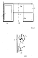
- Fig.1 is a rear view of a front wall 1 of a cab of a commercial vehicle shown schematically, ie the line of sight is directed from the interior of the cab on the front wall 1. It can be seen relative to a central vertical axis 4 substantially symmetrical halves 6, 8, wherein for a standard version, a steering column 10 with a steering shaft 12 for a steering wheel 14 overlapping jacket tube 16 and attached to a pedal bracket 20 Pedal module 18 comprising accelerator pedals 26 such as an accelerator pedal, a brake pedal, a clutch pedal and a sensor for recording the pedal movements in the left half 6 arranged, but not for drawing reasons in Fig.1 but in Fig.2 are shown.
- accelerator pedals 26 such as an accelerator pedal, a brake pedal, a clutch pedal and a sensor for recording the pedal movements in the left half 6 arranged, but not for drawing reasons in Fig.1 but in Fig.2 are shown.
- the storage for the accelerator pedals 26 is formed on the pedal module 18, so that the pedal carrier 20 consists only in a bearing plate or receptacle for the pedal module 18.
- the accelerator pedals 26 could also be accommodated directly on the pedal carrier 20, which then has to accommodate not only the pedal bearings but also the displacement or angle sensor sensors.
- At least the jacket tube 16 of the steering column 10 and the pedal carrier 20 parts of the supporting structure of the cab which includes, among other things, the front wall 1 and associated with this frame parts 24.
- Under the load-bearing structure of the cab continue to be understood all those structural components such as frames, windows, front, side, and rear walls, the roof, the floor, as well as all stiffeners, which to achieve the desired strength and (bending, torsion -) Contribute to the rigidity of the cab and which are covered by the power flow due to its own weight or external forces.
- At least the jacket tube 16 of the steering column 10 and the pedal carrier 20 combined to form a common unit 2, which is part of the supporting structure 1, 24 of the cab and with this material, force or positively connected.
- This summary in a structural unit 2 may, for example, as in Fig.2 shown by a one-piece design of the jacket tube 16 of the steering column 10 and the pedal bracket 20 or by flanging the individual components or assemblies 16, 20 done.
- the front wall 1 of the cab 2 and the assembly 2 of casing tube 16 and pedal carrier 20 may be designed so that both right and left-hand drive vehicles can be realized without the front wall 1 or the unit 2 would have to be changed.
- the assembly 2 is integrated into the supporting structure of the cab, here in the front wall 1 and its frame parts 24th
- a one or more parts, not shown in the figures attached to the front wall 1 dashboard may also be part of the supporting structure 1, 24. According to a development of these measures, the dashboard can at least partially be part of a deformation zone of the driver's cab 2.
- further parts of the load-bearing structure of the driver's cab can be integrated into the module 22 as well as other vehicle-related assemblies.
- any control functions controlling vehicle functions may be integrated, in particular a central vehicle control unit, a brake control unit of an electronic braking system (EBS), a control unit of an electronic stability program (ESP) or an airbag control unit.
- EBS electronic braking system
- ESP electronic stability program
Landscapes
- Engineering & Computer Science (AREA)
- Mechanical Engineering (AREA)
- Transportation (AREA)
- Chemical & Material Sciences (AREA)
- Combustion & Propulsion (AREA)
- Body Structure For Vehicles (AREA)
- Steering Controls (AREA)
- Air Bags (AREA)
Description
- Stand der Technik
- Die Erfindung geht aus von einem Fahrerhaus eines Nutzfahrzeugs, gemäß dem Oberbegriff von Anspruch 1.
- Aus dem Stand der Technik sind Fahrerhäuser bekannt, bei welchen das Mantelrohr der Lenksäule und der Pedalträger getrennte Baueinheiten darstellen, welche an der tragenden Struktur des Fahrerhauses befestigt sind.
- Gemäß der gattungsbildenden
WO 00/71407 A1 - Gemäß der
US 4 597 461 A1 wird ein vorgefertigtes Modul für den Cockpit-Bereich eines Fahrzeugs vorgeschlagen, welches von einer vorderen, den Motorraum begrenzenden Spritzwand getragen wird. DieUS 2005/028 offenbart ein eine Lenksäule und eine Pedalerie eines Fahrzeugs zusammenfassendes Modul. - Der vorliegenden Erfindung liegt demgegenüber die Aufgabe zugrunde, ein Fahrerhaus der eingangs erwähnten Art derart weiter zu entwickeln, dass durch eine Integration weiterer Komponenten die Montage vereinfacht und die Funktionssicherheit erhöht wird.
- Diese Aufgabe wird erfindungsgemäß durch die Merkmale von Anspruch 1 gelöst.
- Gemäß Patentanspruch 1 sind wenigstens das Mantelrohr der Lenksäule und der Pedalträger nicht wie beim Stand der Technik lediglich an der tragenden Struktur befestigt sind, sondern Teile der tragenden Struktur des Fahrerhauses selbst bilden. In dem diese Bauteile in die tragende Struktur des Fahrerhauses einbezogen werden, tragen sie vorteilhaft zur Erhöhung von deren Steifigkeit bei. Dadurch wird beispielsweise durch Materiaieinsparungen wie weiniger Rahmenteile, Versteifungsrippen oder -sicken weniger Gewicht wie auch eine flexiblere Gestaltung der tragenden Struktur möglich. Nicht zuletzt trägt die Funktionsvereinigung als Trägerbauteile wenigstens für die Lenkspindel und die Fahrpedale und zugleich als Strukturbauteil zur Kostenersparnis bei.
- Weiterhin sind das Mantelrohr der Lenksäule und der Pedalträger zu einer gemeinsamen Baueinheit zusarrimengefasst, welche Teil der tragenden Struktur des Fahrerhauses ist. Diese Zusammenfassung in einer baulichen Einheit kann beispielsweise durch eine einstückige Ausführung des Mantelrohrs der Lenksäule und des Pedalträgers oder durch Aneinanderflanschen der Einzelbauteile oder Baugruppen erfolgen.
- Erfindungsgemäß sind zusätzlich wenigstens folgende Bauteile oder Baugruppen mit der Baueinheit zu einem separat vorfertigbaren Modul zusammengefasst:
- a) wenigstens ein elektronisches Steuergerät für eine oder mehrere Fahrzeugfunktionen,
- b) wenigstens ein an der Frontwand befestigter Kühlergrill,
- c) das Lenkrad,
- d) wenigstens ein Airbag-System inklusive wenigstens eines Beschleunigungssensors,
- e) wenigstens ein Radarsensor einer adaptiven Geschwindigkeitsregelung (ACC),
- f) wenigstens ein an der Frontwand gehaltener Scheinwerfer und/oder wenigstens eine Signalleuchte,
- g) eine an der Frontwand gelagerte Motorhaube,
- h) ein Fahrpedal wie ein Brems-, Gas- oder Kupplungspedal,
- i) wenigstens ein Sensor zur Aufnahme von Bewegungen der Lenkspindel und/oder der Fahrpedale.
- Durch diese Maßnahme wird die Fertigung des Fahrerhauses erleichtert, da das separate Modul eine einfachere Montage der genannten Bauteile und Baugruppen ermöglicht als dies bei einem bereits am Nutzfahrzeuge montierten Fahrerhaus der Fall ist. Dies trägt ebenfalls zu einer Reduzierung der Fertigungskosten bei.
- Weil die Pedal- bzw. die Lenkspindetbewegungen in der Regel von elektrische Drehwinkel- oder Wegaufnehmern detektiert und die sensierten Signale von elektronischen Steuergeräten im Rahmen einer Regelstruktur in Stellsignale für entsprechende Aktoren gewandelt werden, bietet die Integration solcher Steuergeräte in das Modul den Vorteil einer kürzeren, mit weniger Aufwand zu verlegenden und weniger störungsanfälligen Verkabelung. Weiterhin ist das Fahrerhaus eines Nutzfahrzeugs in der Regel gegenüber dem Rahmen kippbar ausgeführt, so dass ein Verbindungskabel, beispielsweise in Form eines CAN-Datenbusses zu einem außerhalb des Fahrerhauses angeordneten Steuergerät einer gewissen mechanischen Beanspruchung ausgesetzt wäre.
- Nicht zuletzt können die Elemente der den Fahrzeugfunktionen zugeordneten Regelstrukturen wie die Sensorik, das Steuergerät, die Verkabelung und u.U. auch die Aktoren in das Modul integriert werden, weil dadurch die Konfiguration und Testläufe vor der Montage des Moduls am Nutzfahrzeug möglich sind und damit die Ausfallsicherheit erhöht wird.
- Durch die in den Unteransprüchen aufgeführten Maßnahmen sind vorteilhafte Weiterbildungen und Verbesserungen der in den unabhängigen Ansprüchen angegebenen Erfindung möglich.
- Gemäß einer Fortbildung können die tragende Struktur und die Baueinheit aus Mantelrohr der Lenksäule und dem Pedalträger so ausgeführt sein, dass sowohl rechts- als auch linksgelenkte Nutzfahrzeuge realisierbar sind. Dies reduziert die Variantenvielfalt und trägt zur Kostenersparnis bei.
- Zur weiteren Erhöhung der Steifigkeit des Fahrerhauses kann ein ein- oder mehrteiliges Armaturenbrett ebenfalls Teil der tragenden Struktur sein, wodurch sich die bereits oben beschriebenen Vorteile ergeben. Gemäß einer Weiterbildung dieser Maßnahmen kann das Armaturenbrett wenigstens teilweise Bestandteil einer Deformationszone des Fahrerhauses sein, wodurch es eine ebenfalls Gewicht sparende Doppelfunktion ausübt. Nicht zuletzt ist dadurch eine weitere Struktur vorhanden, um das Deformationsverhalten des Fahrerhauses zu beeinflussen.
- Dabei können in das Modul beliebige Fahrzeugfunktionen steuernde Steuergeräte integriert sein, insbesondere ein zentrales Fahrzeugsteuergerät, ein Bremssteuergerät eines elektronischen Bremssystems (EBS), ein Steuergerät eines elektronischen Stabilitätsprogramms (ESP) oder ein Airbag-Steuergerät.
- Genaueres geht aus der folgenden Beschreibung eines Ausführungsbeispiels hervor.
- Nachstehend ist ein Ausführungsbeispiet der Erfindung in der Zeichnung dargestellt und in der nachfolgenden Beschreibung näher erläutert. In der Zeichnung zeigt
- Fig.1
- eine stark schematisierte Rückansicht einer Frontwand eines Fahrerhauses eines Nutzfahrzeugs, bei welcher die Erfindung gemäß einer bevorzugten Ausführungsform verwirklicht ist:
- Fig.2
- einen Ausschnitt von
Fig.1 in Form einer Baueinheit bestehend aus dem Mantelrohr der Lenksäule und dem Pedalträger. - In
Fig.1 ist eine Rückansicht einer Frontwand 1 eines Fahrerhauses eines Nutzfahrzeugs schematisch gezeigt, d.h. die Blickrichtung richtet sich vom Inneren des Fahrerhauses auf die Frontwand 1. Zu erkennen sind bezogen auf eine zentrale Vertikalachse 4 im wesentlichen symmetrische Hälften 6, 8, wobei für eine Standardausführung eine Lenksäule 10 mit dem eine Lenkspindel 12 für ein Lenkrad 14 lagernden Mantelrohr 16 und ein an einem Pedalträger 20 befestigtes Pedalmodul 18 umfassend Fahrpedale 26 wie beispielsweise ein Gaspedal, ein Bremspedal, ein Kupplungspedal sowie eine Sensorik zur Aufnahme der Pedalbewegungen in der linken Hälfte 6 angeordnet, aber aus zeichnerischen Gründen nicht inFig.1 , sondern inFig.2 dargestellt sind. - In diesem Fall ist die Lagerung für die Fahrpedale 26 am Pedalmodul 18 ausgebildet, so dass der Pedalträger 20 lediglich in einer Lagerplatte oder Aufnahme für das Pedalmodul 18 besteht. Gemäß einer Alternative könnten die Fahrpedale 26 aber auch direkt am Pedalträger 20 aufgenommen sein, welcher dann neben den Pedallagern auch die Weg- oder Winkelaufnehmer-Sensorik aufnehmen muss.
- Dabei bilden wenigstens das Mantelrohr 16 der Lenksäule 10 und der Pedalträger 20 Teile der tragenden Struktur des Fahrerhauses, welche unter anderem die Frontwand 1 und mit dieser verbundene Rahmenteile 24 umfasst. Unter der tragenden Struktur des Fahrerhauses sollen weiterhin alle diejenigen Strukturbauteile wie beispielsweise Rahmen, Scheiben, Front-, Seiten-, und Rückwände, das Dach, der Boden, sowie alle Versteifungen verstanden werden, welche zur Erzielung der gewünschten Festigkeit und (Biege-, Torsions-) Steifigkeit des Fahrerhauses einen Beitrag leisten und welche von dem durch Eigengewicht oder äußere Kräfte bedingten Kraftfluss erfasst sind.
- Besonders bevorzugt sind dabei wenigstens das Mantelrohr 16 der Lenksäule 10 und der Pedalträger 20 zu einer gemeinsamen Baueinheit 2 zusammengefasst, welche Teil der tragenden Struktur 1, 24 des Fahrerhauses und mit dieser stoff-, kraft- oder formschlüssig verbunden ist. Diese Zusammenfassung in einer baulichen Einheit 2 kann beispielsweise, wie in
Fig.2 gezeigt durch eine einstückige Ausführung des Mantelrohrs 16 der Lenksäule 10 und des Pedalträgers 20 oder durch Aneinanderflanschen der Einzelbauteile oder Baugruppen 16, 20 erfolgen. - Die Frontwand 1 des Fahrerhauses 2 und die Baueinheit 2 aus Mantelrohr 16 und Pedalträger 20 können so ausgeführt sein, dass sowohl rechts- als auch linksgelenkte Nutzfahrzeuge realisierbar sind, ohne dass die Frontwand 1 oder die Baueinheit 2 verändert werden müssten. Zu diesem Zweck können beispielsweise in der linken Hälfte 6 und in der rechten Hälfte 8 der Frontwand 1 identische Aufnahmen, Anschlüsse oder Aussparungen für die Baueinheit 2 vorgesehen sein, an welchen diese aufgenommen und mit welchen sie stoff-, form- oder kraftschlüssig verbunden werden kann. Die Aufnahmen, Anschlüsse oder Aussparungen sind dabei so ausgebildet, dass wenigstens ein Teil des in ihrem Bereich vorhandenen Kraftflusses durch oder entlang der Baueinheit 2 geleitet wird. Auf diese Weise wird die Baueinheit 2 in die tragende Struktur des Fahrerhauses integriert, hier in die Frontwand 1 und deren Rahmenteile 24.
- Zur weiteren Erhöhung der Steifigkeit des Fahrerhauses 2 kann ein an der Frontwand 1 befestigtes ein- oder mehrteiliges, in den Figuren nicht gezeigtes Armaturenbrett ebenfalls Teil der tragenden Struktur 1, 24 sein. Gemäß einer Weiterbildung dieser Maßnahmen kann das Armaturenbrett wenigstens teilweise Bestandteil einer Deformationszone des Fahrerhauses 2 sein.
- Besonders bevorzugt können wenigstens folgende, in den Figuren nicht gezeigte Bauteile oder Baugruppen mit wenigstens der Frontwand 1 des Fahrerhauses, der Baueinheit 2 aus dem Mantelrohr 16 und dem Pedalträger 20 sowie gegebenenfalls dem Armaturenbrett als tragender Struktur zu einem separat vorfertigbaren Modul 22 zusammengefasst sein :
- a) wenigstens ein elektronisches Steuergerät für eine oder mehrere Fahrzeugfunktionen,
- b) wenigstens ein an der Frontwand 1 befestigter Kühlergrill,
- c) das Lenkrad 14,
- d) wenigstens ein am Lenkkrad 14 gehaltenes Airbag-System inklusive wenigstens eines Beschleunigungssensors,
- e) wenigstens einen Radarsensor einer adaptiven Geschwindigkeitsregelung (ACC),
- f) wenigstens einen an der Frontwand 1 gehaltenen Scheinwerfer und/oder wenigstens eine Signalleuchte,
- g) eine an der Frontwand 1 gelagerte Motorhaube,
- h) ein Fahrpedal 26 wie ein Brems-, Gas- oder Kupplungspedal,
- i) wenigstens einen Sensor zur Aufnahme von Bewegungen der Lenkspindel 12 und/oder der Fahrpedale 26.
- Gemäß einer Fortbildung können weitere Teile der tragenden Struktur des Fahrerhauses wie etwa Seitenwände, Boden, Dach und Rahmenteile in das Modul 22 sowie weitere fahrzeugfunktionsbezogene Baugruppen integriert sein.
- Nicht zuletzt können in das Modul 22 beliebige Fahrzeugfunktionen steuernde Steuergeräte integriert sein, insbesondere ein zentrales Fahrzeugsteuergerät, ein Bremssteuergerät eines elektronischen Bremssystems (EBS), ein Steuergerät eines elektronischen Stabilitätsprogramms (ESP) oder ein Airbag-Steuergerät.
-
- 1
- Frontwand
- 2
- Baueinheit
- 4
- Vertikalachse
- 6
- Hälfte
- 8
- Hälfte
- 10
- Lenksäule
- 12
- Lenkspindel
- 14
- Lenkrad
- 16
- Mantelrohr
- 18
- Pedaleinrichtung
- 20
- Pedalträger
- 22
- Modul
- 24
- Rahmenteile
- 26
- Fahrpedal
Claims (6)
- Fahrerhaus eines Nutzfahrzeugs, beinhaltend eine Lenksäule (10) umfassend eine in einem Mantelrohr (16) drehbar gelagerte Lenkspindel (12) und wenigstens einen Pedalträger (20), an welchem wenigstens ein Fahrpedal (26) gelagert ist, wobei wenigstens das Mantelrohr (16) der Lenksäule (10) und der Pedalträger (20) zu einer gemeinsamen Baueinheit (2) zusammengefasst sind, welche einen Teil der tragenden Struktur (1, 24) des Fahrerhauses bildet, dadurch gekennzeichnet, dass zusätzlich wenigstens folgende Bauteile oder Baugruppen mit der Baueinheit (2) zu einem separat vorfertigbaren Modul (22) zusammengefasst sind:a) wenigstens ein Sensor zur Aufnahme von Bewegungen der Lenkspindel (12) und/oder wenigstens eines Fahrpedals (26),b) wenigstens ein elektronisches Steuergerät für eine oder mehrere Fahrzeugfunktionen,c) wenigstens ein Kühlergrill,d) das Lenkrad (14),e) wenigstens ein Airbag-System inklusive wenigstens eines Beschleuneigungssensors.f) wenigstens ein Radarsensor einer adaptiven Geschwindigkeitsregelung (ACC),g) wenigstens ein Scheinwerfer und/oder wenigstens eine Signalleuchte,h) eine Motorhaube,i) das wenigstens eine Fahrpedal (26).
- Fahrerhaus nach Anspruch 1, dadurch gekennzeichnet, dass wenigstens ein Teil (1, 6, 8, 24) der tragenden Struktur und die Baueinheit (2) so ausgeführt sind, dass sowohl rechts- als auch linksgelenkte Nutzfahrzeuge realisierbar sind.
- Fahrerhaus nach wenigstens einem der vorhergehenden Ansprüche, dadurch gekennzeichnet, dass ein ein- oder mehrteiliges Armaturenbrett ebenfalls Teil der tragenden Struktur (1,24) des Fahrerhauses (2) ist.
- Fahrerhaus nach Anspruch 3, dadurch gekennzeichnet, dass das ein- oder mehrteilige Armaturenbrett wenigstens teilweise Bestandteil einer Deformationszone des Fahrerhauses (2) ist.
- Fahrerhaus nach wenigstens einem der vorhergehenden Ansprüche, dadurch gekennzeichnet, dass das elektronische Steuergerät wenigstens eines aus der Gruppe der folgenden Steuergeräte ist:a) ein zentrales Fahrzeugsteuergerät,b) ein Bremssteuergerät eines elektronischen Bremssystems (EBS),c) ein Airbag-Steuergerät,d) ein Steuergerät eines elektronischen Stabilitätsprogramms (ESP),e) ein Steuergerät für die adaptive Geschwindigkeitsregelung (ACC) :
- Fahrerhaus nach wenigstens einem der vorhergehenden Ansprüche, dadurch gekennzeichnet, dass der Teil der in das Modul (22) integrierten tragenden Struktur wenigstens eine Frontwand (1, 24) des Fahrerhauses beinhaltet.
Applications Claiming Priority (2)
| Application Number | Priority Date | Filing Date | Title |
|---|---|---|---|
| DE102006015650A DE102006015650A1 (de) | 2006-04-04 | 2006-04-04 | Fahrerhaus eines Nutzfahrzeugs mit in die tragende Struktur integrierten Kabinenbauteilen |
| PCT/EP2007/003038 WO2007115764A1 (de) | 2006-04-04 | 2007-04-04 | Fahrerhaus eines nutzfahrzeugs mit in die tragende struktur integrierten kabinenbauteilen |
Publications (2)
| Publication Number | Publication Date |
|---|---|
| EP2004477A1 EP2004477A1 (de) | 2008-12-24 |
| EP2004477B1 true EP2004477B1 (de) | 2009-08-12 |
Family
ID=38080957
Family Applications (1)
| Application Number | Title | Priority Date | Filing Date |
|---|---|---|---|
| EP07723979A Not-in-force EP2004477B1 (de) | 2006-04-04 | 2007-04-04 | Fahrerhaus eines nutzfahrzeugs mit in die tragende struktur integrierten kabinenbauteilen |
Country Status (6)
| Country | Link |
|---|---|
| US (1) | US20100049404A1 (de) |
| EP (1) | EP2004477B1 (de) |
| JP (1) | JP2009532260A (de) |
| AT (1) | ATE439291T1 (de) |
| DE (2) | DE102006015650A1 (de) |
| WO (1) | WO2007115764A1 (de) |
Families Citing this family (1)
| Publication number | Priority date | Publication date | Assignee | Title |
|---|---|---|---|---|
| FR3149581A1 (fr) * | 2023-06-07 | 2024-12-13 | Psa Automobiles Sa | Tablier de véhicule à platine réversible. |
Family Cites Families (25)
| Publication number | Priority date | Publication date | Assignee | Title |
|---|---|---|---|---|
| US2798568A (en) * | 1956-02-15 | 1957-07-09 | Mack Trucks | Cab-over engine truck having a lift-type cab thereon |
| AT317000B (de) * | 1971-12-31 | 1974-08-12 | Steyr Daimler Puch Ag | Schlepper |
| US3812615A (en) * | 1972-06-01 | 1974-05-28 | Celanese Corp | Method of coating soil with an agricultural mulch |
| US3935920A (en) * | 1974-07-17 | 1976-02-03 | Paccar Inc. | Grille system for tilt cab truck |
| US4126202A (en) * | 1977-07-20 | 1978-11-21 | Massey-Ferguson, Inc. | Vehicle control box module |
| DE2754678C2 (de) * | 1977-12-08 | 1990-03-08 | International Harvester Company Mbh, 4040 Neuss | Anordnung eines Tragelements für die Bedienungspedale an der Frontseite einer Fahrerkabine |
| SE429123B (sv) * | 1979-01-16 | 1983-08-15 | Saab Scania Ab | Arrangemang for pedalstell i fordon |
| US4297810A (en) * | 1980-03-03 | 1981-11-03 | Hansford William B | Sprayable hydromulch |
| DE3315646C2 (de) * | 1983-04-29 | 1989-06-08 | Adam Opel AG, 6090 Rüsselsheim | Vormontierte Baueinheit für den Spritzwand-Bereich von Kraftfahrzeugen, insbesondere Personenkraftwagen, und Verfahren zum Einbau einer solchen vormontierten Baueinheit |
| GB2187144B (en) * | 1986-02-28 | 1990-01-10 | Trw Cam Gears Ltd | A vehicle with a collapsible steering column assembly |
| JPH1016702A (ja) * | 1996-06-30 | 1998-01-20 | Isuzu Motors Ltd | 車両の衝突センサー取付装置 |
| AU5590100A (en) * | 1999-05-26 | 2000-12-12 | International Truck Intellectual Property Company, Llc | Symmetrical dash reinforcement |
| US6293632B1 (en) * | 1999-06-11 | 2001-09-25 | John F. Grote | Vehicular brake-by-wire system |
| DE60013596T2 (de) * | 1999-06-24 | 2005-02-03 | International Truck Intellectual Property Co., LLC, Warrenville | Fahrer-steuerungsmodul |
| DE19946934B4 (de) * | 1999-09-30 | 2011-09-29 | Ramsle Technology Group Gmbh, Llc | Modul mit Winkelsensorik, berührungsloser Energieübertragung und berührungsloser Informationsübertragung |
| US6351962B1 (en) * | 1999-12-06 | 2002-03-05 | Denso Corporation | Cockpit module assembly including air conditioner for vehicle |
| US6491322B1 (en) * | 2000-03-21 | 2002-12-10 | Lear Corporation | Energy absorbing bracket assembly for vehicle knee bolster |
| US6562882B2 (en) * | 2001-06-29 | 2003-05-13 | Scott Harrison | Soil formulation for resisting erosion |
| US7407190B2 (en) * | 2003-01-31 | 2008-08-05 | Delphi Technologies, Inc. | Steering column assembly |
| US7255366B2 (en) * | 2003-01-31 | 2007-08-14 | Delphi Technologies, Inc. | Steering column assembly |
| US20050057087A1 (en) * | 2003-08-01 | 2005-03-17 | Bruce Ahnafield | Foot control system for a vehicle |
| DE10360646A1 (de) * | 2003-12-23 | 2005-07-28 | Daimlerchrysler Ag | Sicherheitseinrichtung für ein Nutzfahrzeug |
| US7363131B2 (en) * | 2004-06-16 | 2008-04-22 | Chrysler Llc | Re-positionable vehicle control-by-wire assembly, method, and system |
| DE102004039998B4 (de) * | 2004-08-18 | 2014-03-27 | Knorr-Bremse Systeme für Nutzfahrzeuge GmbH | Nutzfahrzeug mit mehreren, von mindestens einem elektronischen Steuergerät gesteuerten elektrischen Einrichtungen |
| US7498930B2 (en) * | 2005-11-04 | 2009-03-03 | Delphi Technologies, Inc. | Communications interface module for vehicle |
-
2006
- 2006-04-04 DE DE102006015650A patent/DE102006015650A1/de not_active Ceased
-
2007
- 2007-04-04 US US12/296,243 patent/US20100049404A1/en not_active Abandoned
- 2007-04-04 AT AT07723979T patent/ATE439291T1/de active
- 2007-04-04 DE DE502007001306T patent/DE502007001306D1/de active Active
- 2007-04-04 JP JP2009503483A patent/JP2009532260A/ja active Pending
- 2007-04-04 WO PCT/EP2007/003038 patent/WO2007115764A1/de not_active Ceased
- 2007-04-04 EP EP07723979A patent/EP2004477B1/de not_active Not-in-force
Also Published As
| Publication number | Publication date |
|---|---|
| DE102006015650A1 (de) | 2007-10-11 |
| ATE439291T1 (de) | 2009-08-15 |
| WO2007115764A1 (de) | 2007-10-18 |
| EP2004477A1 (de) | 2008-12-24 |
| WO2007115764A8 (de) | 2008-01-10 |
| DE502007001306D1 (de) | 2009-09-24 |
| JP2009532260A (ja) | 2009-09-10 |
| US20100049404A1 (en) | 2010-02-25 |
Similar Documents
| Publication | Publication Date | Title |
|---|---|---|
| DE102018115720B4 (de) | Lenkrad mit einer festen exzentrischen mittelnabe | |
| US5120106A (en) | Structure of a front body of a motor vehicle | |
| DE102019130548A1 (de) | Verfahren zum montieren eines fahrzeugs, einschliesslich eines integrierten innenmoduls und eines top-hat | |
| EP1621384B1 (de) | Kraftfahrzeug-Hecktür | |
| DE19839521C1 (de) | Vorbaustruktur für ein Kraftfahrzeug | |
| EP1781499B1 (de) | Nutzfahrzeug mit mehreren jeweils von mindestens einem elektronischen steuergerät gesteuerten elektrischen einrichtungen | |
| EP3617040B1 (de) | Fahrerhausfrontmodul und verfahren zur herstellung eines fahrerhauses | |
| DE102009013895B4 (de) | Fahrzeug mit einer Einrichtung zur Regelung der Fahrdynamik mit in einer gemeinsamen Baueinheit integriertem Lenkwinkelsensor, Gierratensensor und Beschleunigungssensor | |
| DE102008062735A1 (de) | Kraftfahrzeug-Sicherheitseinheit | |
| DE102005060173A1 (de) | Sensoranordnung und Verfahren zum Ermitteln der Bewegung eines Fahrzeugaufbaus | |
| DE102022114950B3 (de) | Kraftfahrzeug mit einem Dachmodul und mindestens zwei Umfeldsensoren | |
| DE102012000542A1 (de) | Fahrerhaus für ein Kraftfahrzeug | |
| EP2004477A1 (de) | Fahrerhaus eines nutzfahrzeugs mit in die tragende struktur integrierten kabinenbauteilen | |
| DE102007057043A1 (de) | Vorrichtung zur Fahrdynamikregelung | |
| DE10317900A1 (de) | Instrumententafeleinheit | |
| WO2009074304A1 (de) | Verfahren und steuersystem zum übertragen von daten zwischen steuervorrichtungen in einem fahrzeug | |
| US20200223496A1 (en) | Steering device | |
| DE102021117177A1 (de) | Kompatibilitätsmodul, Vorrichtung, Verfahren sowie ein Computerprogramm zur Erweiterung und/oder Nachrüstung eines Funktionsumfangs eines Fahrzeugs | |
| DE102004026283A1 (de) | Trägereinheit für einen Frontbereich eines Kraftfahrzeugs | |
| DE10203207B4 (de) | Elektromechanische Bremsanlage | |
| DE102007028985B4 (de) | Steuervorrichtung für kombinierte Kfz-Sicherheitssysteme | |
| DE102009042871A1 (de) | Fahrzeug mit einer Vorrichtung zur Leuchtweitenregulierung und einer Diebstahlwarnanlage sowie Verfahren | |
| EP2507114A1 (de) | Gehäuse für eine kraftwagenkomponente | |
| CN206201979U (zh) | 离合踏板总成 | |
| DE102020200531A1 (de) | Integrierte Baugruppe für ein Kraftfahrzeug, Kraftfahrzeug mit einer integrierten Baugruppe |
Legal Events
| Date | Code | Title | Description |
|---|---|---|---|
| PUAI | Public reference made under article 153(3) epc to a published international application that has entered the european phase |
Free format text: ORIGINAL CODE: 0009012 |
|
| 17P | Request for examination filed |
Effective date: 20081104 |
|
| AK | Designated contracting states |
Kind code of ref document: A1 Designated state(s): AT BE BG CH CY CZ DE DK EE ES FI FR GB GR HU IE IS IT LI LT LU LV MC MT NL PL PT RO SE SI SK TR |
|
| GRAP | Despatch of communication of intention to grant a patent |
Free format text: ORIGINAL CODE: EPIDOSNIGR1 |
|
| GRAS | Grant fee paid |
Free format text: ORIGINAL CODE: EPIDOSNIGR3 |
|
| GRAA | (expected) grant |
Free format text: ORIGINAL CODE: 0009210 |
|
| AK | Designated contracting states |
Kind code of ref document: B1 Designated state(s): AT BE BG CH CY CZ DE DK EE ES FI FR GB GR HU IE IS IT LI LT LU LV MC MT NL PL PT RO SE SI SK TR |
|
| REG | Reference to a national code |
Ref country code: GB Ref legal event code: FG4D Free format text: NOT ENGLISH |
|
| REG | Reference to a national code |
Ref country code: CH Ref legal event code: EP |
|
| REG | Reference to a national code |
Ref country code: IE Ref legal event code: FG4D |
|
| REF | Corresponds to: |
Ref document number: 502007001306 Country of ref document: DE Date of ref document: 20090924 Kind code of ref document: P |
|
| LTIE | Lt: invalidation of european patent or patent extension |
Effective date: 20090812 |
|
| PG25 | Lapsed in a contracting state [announced via postgrant information from national office to epo] |
Ref country code: IS Free format text: LAPSE BECAUSE OF FAILURE TO SUBMIT A TRANSLATION OF THE DESCRIPTION OR TO PAY THE FEE WITHIN THE PRESCRIBED TIME-LIMIT Effective date: 20091212 Ref country code: ES Free format text: LAPSE BECAUSE OF FAILURE TO SUBMIT A TRANSLATION OF THE DESCRIPTION OR TO PAY THE FEE WITHIN THE PRESCRIBED TIME-LIMIT Effective date: 20091123 Ref country code: SE Free format text: LAPSE BECAUSE OF FAILURE TO SUBMIT A TRANSLATION OF THE DESCRIPTION OR TO PAY THE FEE WITHIN THE PRESCRIBED TIME-LIMIT Effective date: 20090812 Ref country code: FI Free format text: LAPSE BECAUSE OF FAILURE TO SUBMIT A TRANSLATION OF THE DESCRIPTION OR TO PAY THE FEE WITHIN THE PRESCRIBED TIME-LIMIT Effective date: 20090812 Ref country code: LT Free format text: LAPSE BECAUSE OF FAILURE TO SUBMIT A TRANSLATION OF THE DESCRIPTION OR TO PAY THE FEE WITHIN THE PRESCRIBED TIME-LIMIT Effective date: 20090812 |
|
| NLV1 | Nl: lapsed or annulled due to failure to fulfill the requirements of art. 29p and 29m of the patents act | ||
| PG25 | Lapsed in a contracting state [announced via postgrant information from national office to epo] |
Ref country code: NL Free format text: LAPSE BECAUSE OF FAILURE TO SUBMIT A TRANSLATION OF THE DESCRIPTION OR TO PAY THE FEE WITHIN THE PRESCRIBED TIME-LIMIT Effective date: 20090812 Ref country code: LV Free format text: LAPSE BECAUSE OF FAILURE TO SUBMIT A TRANSLATION OF THE DESCRIPTION OR TO PAY THE FEE WITHIN THE PRESCRIBED TIME-LIMIT Effective date: 20090812 Ref country code: SI Free format text: LAPSE BECAUSE OF FAILURE TO SUBMIT A TRANSLATION OF THE DESCRIPTION OR TO PAY THE FEE WITHIN THE PRESCRIBED TIME-LIMIT Effective date: 20090812 Ref country code: PL Free format text: LAPSE BECAUSE OF FAILURE TO SUBMIT A TRANSLATION OF THE DESCRIPTION OR TO PAY THE FEE WITHIN THE PRESCRIBED TIME-LIMIT Effective date: 20090812 |
|
| REG | Reference to a national code |
Ref country code: IE Ref legal event code: FD4D |
|
| PG25 | Lapsed in a contracting state [announced via postgrant information from national office to epo] |
Ref country code: PT Free format text: LAPSE BECAUSE OF FAILURE TO SUBMIT A TRANSLATION OF THE DESCRIPTION OR TO PAY THE FEE WITHIN THE PRESCRIBED TIME-LIMIT Effective date: 20091212 Ref country code: BG Free format text: LAPSE BECAUSE OF FAILURE TO SUBMIT A TRANSLATION OF THE DESCRIPTION OR TO PAY THE FEE WITHIN THE PRESCRIBED TIME-LIMIT Effective date: 20091112 |
|
| PG25 | Lapsed in a contracting state [announced via postgrant information from national office to epo] |
Ref country code: IE Free format text: LAPSE BECAUSE OF FAILURE TO SUBMIT A TRANSLATION OF THE DESCRIPTION OR TO PAY THE FEE WITHIN THE PRESCRIBED TIME-LIMIT Effective date: 20090812 Ref country code: RO Free format text: LAPSE BECAUSE OF FAILURE TO SUBMIT A TRANSLATION OF THE DESCRIPTION OR TO PAY THE FEE WITHIN THE PRESCRIBED TIME-LIMIT Effective date: 20090812 Ref country code: EE Free format text: LAPSE BECAUSE OF FAILURE TO SUBMIT A TRANSLATION OF THE DESCRIPTION OR TO PAY THE FEE WITHIN THE PRESCRIBED TIME-LIMIT Effective date: 20090812 Ref country code: DK Free format text: LAPSE BECAUSE OF FAILURE TO SUBMIT A TRANSLATION OF THE DESCRIPTION OR TO PAY THE FEE WITHIN THE PRESCRIBED TIME-LIMIT Effective date: 20090812 Ref country code: CZ Free format text: LAPSE BECAUSE OF FAILURE TO SUBMIT A TRANSLATION OF THE DESCRIPTION OR TO PAY THE FEE WITHIN THE PRESCRIBED TIME-LIMIT Effective date: 20090812 |
|
| PG25 | Lapsed in a contracting state [announced via postgrant information from national office to epo] |
Ref country code: SK Free format text: LAPSE BECAUSE OF FAILURE TO SUBMIT A TRANSLATION OF THE DESCRIPTION OR TO PAY THE FEE WITHIN THE PRESCRIBED TIME-LIMIT Effective date: 20090812 |
|
| PLBE | No opposition filed within time limit |
Free format text: ORIGINAL CODE: 0009261 |
|
| STAA | Information on the status of an ep patent application or granted ep patent |
Free format text: STATUS: NO OPPOSITION FILED WITHIN TIME LIMIT |
|
| 26N | No opposition filed |
Effective date: 20100517 |
|
| PG25 | Lapsed in a contracting state [announced via postgrant information from national office to epo] |
Ref country code: GR Free format text: LAPSE BECAUSE OF FAILURE TO SUBMIT A TRANSLATION OF THE DESCRIPTION OR TO PAY THE FEE WITHIN THE PRESCRIBED TIME-LIMIT Effective date: 20091113 |
|
| BERE | Be: lapsed |
Owner name: KNORR-BREMSE SYSTEME FUR NUTZFAHRZEUGE G.M.B.H. Effective date: 20100430 |
|
| PG25 | Lapsed in a contracting state [announced via postgrant information from national office to epo] |
Ref country code: MC Free format text: LAPSE BECAUSE OF NON-PAYMENT OF DUE FEES Effective date: 20100430 |
|
| REG | Reference to a national code |
Ref country code: FR Ref legal event code: ST Effective date: 20101230 |
|
| PG25 | Lapsed in a contracting state [announced via postgrant information from national office to epo] |
Ref country code: IT Free format text: LAPSE BECAUSE OF FAILURE TO SUBMIT A TRANSLATION OF THE DESCRIPTION OR TO PAY THE FEE WITHIN THE PRESCRIBED TIME-LIMIT Effective date: 20090812 Ref country code: BE Free format text: LAPSE BECAUSE OF NON-PAYMENT OF DUE FEES Effective date: 20100430 |
|
| PG25 | Lapsed in a contracting state [announced via postgrant information from national office to epo] |
Ref country code: MT Free format text: LAPSE BECAUSE OF FAILURE TO SUBMIT A TRANSLATION OF THE DESCRIPTION OR TO PAY THE FEE WITHIN THE PRESCRIBED TIME-LIMIT Effective date: 20090812 |
|
| REG | Reference to a national code |
Ref country code: CH Ref legal event code: PL |
|
| GBPC | Gb: european patent ceased through non-payment of renewal fee |
Effective date: 20110404 |
|
| PG25 | Lapsed in a contracting state [announced via postgrant information from national office to epo] |
Ref country code: LI Free format text: LAPSE BECAUSE OF NON-PAYMENT OF DUE FEES Effective date: 20110430 Ref country code: CH Free format text: LAPSE BECAUSE OF NON-PAYMENT OF DUE FEES Effective date: 20110430 |
|
| PG25 | Lapsed in a contracting state [announced via postgrant information from national office to epo] |
Ref country code: GB Free format text: LAPSE BECAUSE OF NON-PAYMENT OF DUE FEES Effective date: 20110404 |
|
| PG25 | Lapsed in a contracting state [announced via postgrant information from national office to epo] |
Ref country code: FR Free format text: LAPSE BECAUSE OF NON-PAYMENT OF DUE FEES Effective date: 20100430 |
|
| PG25 | Lapsed in a contracting state [announced via postgrant information from national office to epo] |
Ref country code: CY Free format text: LAPSE BECAUSE OF FAILURE TO SUBMIT A TRANSLATION OF THE DESCRIPTION OR TO PAY THE FEE WITHIN THE PRESCRIBED TIME-LIMIT Effective date: 20090812 |
|
| PG25 | Lapsed in a contracting state [announced via postgrant information from national office to epo] |
Ref country code: LU Free format text: LAPSE BECAUSE OF NON-PAYMENT OF DUE FEES Effective date: 20100404 Ref country code: HU Free format text: LAPSE BECAUSE OF FAILURE TO SUBMIT A TRANSLATION OF THE DESCRIPTION OR TO PAY THE FEE WITHIN THE PRESCRIBED TIME-LIMIT Effective date: 20100213 |
|
| PG25 | Lapsed in a contracting state [announced via postgrant information from national office to epo] |
Ref country code: TR Free format text: LAPSE BECAUSE OF FAILURE TO SUBMIT A TRANSLATION OF THE DESCRIPTION OR TO PAY THE FEE WITHIN THE PRESCRIBED TIME-LIMIT Effective date: 20090812 |
|
| REG | Reference to a national code |
Ref country code: AT Ref legal event code: MM01 Ref document number: 439291 Country of ref document: AT Kind code of ref document: T Effective date: 20120404 |
|
| PG25 | Lapsed in a contracting state [announced via postgrant information from national office to epo] |
Ref country code: AT Free format text: LAPSE BECAUSE OF NON-PAYMENT OF DUE FEES Effective date: 20120404 |
|
| PGFP | Annual fee paid to national office [announced via postgrant information from national office to epo] |
Ref country code: DE Payment date: 20200423 Year of fee payment: 14 |
|
| REG | Reference to a national code |
Ref country code: DE Ref legal event code: R119 Ref document number: 502007001306 Country of ref document: DE |
|
| PG25 | Lapsed in a contracting state [announced via postgrant information from national office to epo] |
Ref country code: DE Free format text: LAPSE BECAUSE OF NON-PAYMENT OF DUE FEES Effective date: 20211103 |