EP2003442A9 - Verfahren zur beurteilung der zellfunktion, system zur beurteilung der zellfunktion, fluoreszenzmikroskopsystem, lichttherapieverfahren und lichttherapiesystem - Google Patents
Verfahren zur beurteilung der zellfunktion, system zur beurteilung der zellfunktion, fluoreszenzmikroskopsystem, lichttherapieverfahren und lichttherapiesystem Download PDFInfo
- Publication number
- EP2003442A9 EP2003442A9 EP07736970A EP07736970A EP2003442A9 EP 2003442 A9 EP2003442 A9 EP 2003442A9 EP 07736970 A EP07736970 A EP 07736970A EP 07736970 A EP07736970 A EP 07736970A EP 2003442 A9 EP2003442 A9 EP 2003442A9
- Authority
- EP
- European Patent Office
- Prior art keywords
- evaluating
- cell function
- cell
- specific site
- site
- Prior art date
- Legal status (The legal status is an assumption and is not a legal conclusion. Google has not performed a legal analysis and makes no representation as to the accuracy of the status listed.)
- Withdrawn
Links
Images


Classifications
-
- G—PHYSICS
- G01—MEASURING; TESTING
- G01N—INVESTIGATING OR ANALYSING MATERIALS BY DETERMINING THEIR CHEMICAL OR PHYSICAL PROPERTIES
- G01N21/00—Investigating or analysing materials by the use of optical means, i.e. using sub-millimetre waves, infrared, visible or ultraviolet light
- G01N21/62—Systems in which the material investigated is excited whereby it emits light or causes a change in wavelength of the incident light
- G01N21/63—Systems in which the material investigated is excited whereby it emits light or causes a change in wavelength of the incident light optically excited
- G01N21/64—Fluorescence; Phosphorescence
- G01N21/6428—Measuring fluorescence of fluorescent products of reactions or of fluorochrome labelled reactive substances, e.g. measuring quenching effects, using measuring "optrodes"
-
- A—HUMAN NECESSITIES
- A61—MEDICAL OR VETERINARY SCIENCE; HYGIENE
- A61B—DIAGNOSIS; SURGERY; IDENTIFICATION
- A61B5/00—Measuring for diagnostic purposes; Identification of persons
- A61B5/0059—Measuring for diagnostic purposes; Identification of persons using light, e.g. diagnosis by transillumination, diascopy, fluorescence
- A61B5/0071—Measuring for diagnostic purposes; Identification of persons using light, e.g. diagnosis by transillumination, diascopy, fluorescence by measuring fluorescence emission
-
- A—HUMAN NECESSITIES
- A61—MEDICAL OR VETERINARY SCIENCE; HYGIENE
- A61N—ELECTROTHERAPY; MAGNETOTHERAPY; RADIATION THERAPY; ULTRASOUND THERAPY
- A61N5/00—Radiation therapy
- A61N5/06—Radiation therapy using light
- A61N5/0613—Apparatus adapted for a specific treatment
- A61N5/062—Photodynamic therapy, i.e. excitation of an agent
-
- G—PHYSICS
- G01—MEASURING; TESTING
- G01N—INVESTIGATING OR ANALYSING MATERIALS BY DETERMINING THEIR CHEMICAL OR PHYSICAL PROPERTIES
- G01N15/00—Investigating characteristics of particles; Investigating permeability, pore-volume or surface-area of porous materials
- G01N15/10—Investigating individual particles
- G01N15/14—Optical investigation techniques, e.g. flow cytometry
- G01N15/1429—Signal processing
- G01N15/1433—Signal processing using image recognition
-
- G—PHYSICS
- G01—MEASURING; TESTING
- G01N—INVESTIGATING OR ANALYSING MATERIALS BY DETERMINING THEIR CHEMICAL OR PHYSICAL PROPERTIES
- G01N21/00—Investigating or analysing materials by the use of optical means, i.e. using sub-millimetre waves, infrared, visible or ultraviolet light
- G01N21/62—Systems in which the material investigated is excited whereby it emits light or causes a change in wavelength of the incident light
- G01N21/63—Systems in which the material investigated is excited whereby it emits light or causes a change in wavelength of the incident light optically excited
- G01N21/64—Fluorescence; Phosphorescence
- G01N21/6408—Fluorescence; Phosphorescence with measurement of decay time, time resolved fluorescence
-
- G—PHYSICS
- G01—MEASURING; TESTING
- G01N—INVESTIGATING OR ANALYSING MATERIALS BY DETERMINING THEIR CHEMICAL OR PHYSICAL PROPERTIES
- G01N21/00—Investigating or analysing materials by the use of optical means, i.e. using sub-millimetre waves, infrared, visible or ultraviolet light
- G01N21/62—Systems in which the material investigated is excited whereby it emits light or causes a change in wavelength of the incident light
- G01N21/63—Systems in which the material investigated is excited whereby it emits light or causes a change in wavelength of the incident light optically excited
- G01N21/64—Fluorescence; Phosphorescence
- G01N21/645—Specially adapted constructive features of fluorimeters
- G01N21/6456—Spatial resolved fluorescence measurements; Imaging
- G01N21/6458—Fluorescence microscopy
-
- G—PHYSICS
- G01—MEASURING; TESTING
- G01N—INVESTIGATING OR ANALYSING MATERIALS BY DETERMINING THEIR CHEMICAL OR PHYSICAL PROPERTIES
- G01N33/00—Investigating or analysing materials by specific methods not covered by groups G01N1/00 - G01N31/00
- G01N33/48—Biological material, e.g. blood, urine; Haemocytometers
- G01N33/50—Chemical analysis of biological material, e.g. blood, urine; Testing involving biospecific ligand binding methods; Immunological testing
- G01N33/5005—Chemical analysis of biological material, e.g. blood, urine; Testing involving biospecific ligand binding methods; Immunological testing involving human or animal cells
- G01N33/5008—Chemical analysis of biological material, e.g. blood, urine; Testing involving biospecific ligand binding methods; Immunological testing involving human or animal cells for testing or evaluating the effect of chemical or biological compounds, e.g. drugs, cosmetics
-
- A—HUMAN NECESSITIES
- A61—MEDICAL OR VETERINARY SCIENCE; HYGIENE
- A61B—DIAGNOSIS; SURGERY; IDENTIFICATION
- A61B5/00—Measuring for diagnostic purposes; Identification of persons
- A61B5/0059—Measuring for diagnostic purposes; Identification of persons using light, e.g. diagnosis by transillumination, diascopy, fluorescence
- A61B5/0062—Arrangements for scanning
- A61B5/0064—Body surface scanning
-
- G—PHYSICS
- G01—MEASURING; TESTING
- G01N—INVESTIGATING OR ANALYSING MATERIALS BY DETERMINING THEIR CHEMICAL OR PHYSICAL PROPERTIES
- G01N1/00—Sampling; Preparing specimens for investigation
- G01N1/28—Preparing specimens for investigation including physical details of (bio-)chemical methods covered elsewhere, e.g. G01N33/50, C12Q
- G01N1/30—Staining; Impregnating ; Fixation; Dehydration; Multistep processes for preparing samples of tissue, cell or nucleic acid material and the like for analysis
-
- G—PHYSICS
- G01—MEASURING; TESTING
- G01N—INVESTIGATING OR ANALYSING MATERIALS BY DETERMINING THEIR CHEMICAL OR PHYSICAL PROPERTIES
- G01N15/00—Investigating characteristics of particles; Investigating permeability, pore-volume or surface-area of porous materials
- G01N15/10—Investigating individual particles
- G01N15/14—Optical investigation techniques, e.g. flow cytometry
- G01N2015/1488—Methods for deciding
Definitions
- the present invention relates to an evaluating method of cell function, an evaluating system of cell function, a fluorescent microscope system, a photodynamic therapy method, and a photodynamic therapy system, applicable to photochemistry, photophysiology, photodynamic effects, and the like in life science.
- Chromophore-assisted laser inactivation (CALI) and phot dynamic therapy (PDT) are among the techniques of photodynamic therapy.
- the former is the technique that suppresses activity of molecules, and the latter is the technique that induces damage to the cell membrane, organelles, and DNA to cause cell death.
- the letter technique, PDT is effective in killing cancer cells. PDT works under the principle that a fluorescent dye in cells absorbs light and creates singlet oxygen and other chemical species, which are generated as by-products when the dye releases fluorescence. These chemical species would then damage part of cells to induce functional depression or cell death (see Patent Document 1, Non-Patent Document 1 , for example)
- phototoxic property has been evaluated only broadly based on whether cells have been killed by irradiation of light.
- the phototoxic property during light exposure is evaluated in real time by measuring the rate or extent of fluorescence bleaching.
- this method suffers from inaccuracy because the bleaching (decay of fluorescence brightness) is not well correlated with phototoxic property (functional depression of living cells).
- Another proposition of the present invention is to provide a photodynamic therapy method capable of realizing an appropriate therapy, and a photodynamic therapy system suitable for such a photodynamic therapy method.
- An evaluating method of cell function of the present invention is a method of evaluating a cell function concerning a living cell, and the method includes dyeing operation of dyeing a specific site of the living cell with a fluorescent dye, measuring operation of measuring a brightness value of fluorescence generated at an adjacent site of the specific site as a result of irradiation of the stained living cell with light, and evaluating operation of evaluating the cell function based on changes in the measured brightness value.
- the cell function may be evaluated based on an amount of light irradiation being spent until the brightness change curve reaches the peak. Further, in the evaluating operation, the cell function may be evaluated based on a brightness value at the peak of the brightness change curve.
- the adjacent site of the specific site may be an area specified by a rectangular shaped frame, or an area specified by a closed and free curved frame or a closed and multiangular shaped frame in which the specific site is excluded from an area including the specific site and an area adjacent to the specific site.
- the brightness value may be a maximum brightness value or a mean brightness value of a plurality of fluorescence brightness values measured in the adjacent site.
- the specific site may be a mitochondrion, and the adjacent site may be a cellular cytoplasm.
- An evaluating system of cell function of the present invention is a system that evaluates a cell function concerning a living cell, the living cell including a specific site stained with a fluorescent dye in advance, and the evaluating system of cell function includes an irradiating unit that irradiates the stained living cell with light, a measuring unit that measures a brightness value of fluorescence generated at an adjacent site of the specific site as a result of the irradiation of light, and an evaluating unit that evaluates the cell function based on changes in the measured brightness value.
- the evaluating unit may evaluate the cell function based on an amount of light irradiation being spent until the brightness change curve reaches the peak. Further the evaluating unit may evaluate the cell function based on a brightness value at the peak of the brightness change curve.
- the adjacent site of the specific site may be an area specified by a rectangular shaped frame, or an area specified by a closed and free curved frame or a closed and multangular shaped frame in which the specific site is excluded from an area including the specific site and an area adjacent to the specific site.
- a photodynamic therapy system of the present invention is a system that irradiates a living cell with light, the living cell including a specific site stained with a fluorescent dye in advance, the system including a therapeutic unit that irradiates the stained living cell with light, a measuring unit that measures a brightness value of fluorescence generated at an adjacent site of the specific site as a result of the irradiation of light, and a presenting unit that presents to an operator changes in the measured brightness value, in real time.
- the present invention realizes an evaluating method of cell function, an evaluating system of cell function, and a fluorescent microscope system that are capable of accurately evaluating phototoxic property.
- the invention also realizes a photodynamic therapy method capable of realizing an appropriate therapy, and a photodynamic therapy system suitable for such a photodynamic therapy method.
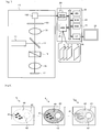
- the fluorescent dye at this light spot generates fluorescence (529 nm), which is incident on the dichroic mirror 13 through the objective lens 16 and the optical scanner 15.
- the fluorescence travels through the dichroic mirror 13 and falls on a pinhole mask 101 through an image-forming lens 19.
- the pinhole mask 101 is conjugate to the specimen 17, so that only the necessary light component of the fluorescence incident on the pinhole mask 101 passes through it.
- the fluorescence passing through the pinhole mask 101 enters a light sensor 102 where photoelectric conversion occurs.
- the fluorescence converted to an electrical signal in the light sensor 102 is then sent to the computer 20.
- the electrical signal is converted to a digital signal and stored in a frame memory 21 of the computer 20.
- the optical scanner 15 and the light sensor 12 are driven in synchronism to two-dimensionally scan the specimen 1 7 with a light spot, thereby repeatedly generating electrical signals.
- a fluorescence image of one frame is obtained from the specimen 1 7 (imaging of the specimen 1 7).
- the imaging magnifications of the objective lens 16 and the image-forming lens 19 are set to values suitable for the observation of microstructures (organelles) of the living cells. Accordingly, the fluorescence image contains one to several living cells.
- a CPU 22 in the computer 20 reads out digital signals accumulated in the frame memory 21 and creates a fluorescence image I of the specimen 17.
- the fluorescence image I is stored in a hard disc drive 25.
- fluorescence images I 1 , I 2 , ..., I N of N frames are accumulated in the hard disc drive 25.
- the fluorescence images I 1 , I 2 , ..., I N are output to the monitor 30 via an interface circuit 26.
- the mitochondria 41 at the stained site appear darker as a result of bleaching, and the cellular cytoplasm 43 adjacent to the mitochondria 41 appears slightly brighter by fluorescing.
- This phenomenon is the indication of the functional depression of the mitochondria 41 incurred by the irradiation of light in the imaging and the resulting extravasation of the fluorescent dye into the cellular cytoplasm 43 from the inner side of the mitochondrial membrane. It should be noted here that not all fluorescent dyes in the mitochondria 41 extravasate to the cellular cytoplasm 43. The extravasation stops at some time point.
- the cellular cytoplasm 43 appears dark by bleaching, and stably maintains a small brightness value as does the mitochondria 41.
- fluorescence occurs not only in the mitochondria 41 at the stained site but in the cellular cytoplasm 43 at the adjacent site in the cell 40. This is related to the extravasation of the fluorescent dye from the mitochondria 41 to the cellular cytoplasm 43, i.e., functional depression of the mitochondria 41.
- the CPU 22 performs a process for determining a reference point (step S1), a process for referring to a brightness change of the reference point (step S2), a process for calculating an evaluating value (step S3), and a process for displaying the evaluating value (step S4), in this order from the top.
- step S1 a process for determining a reference point
- step S2 a process for referring to a brightness change of the reference point
- step S3 a process for calculating an evaluating value
- step S4 a process for displaying the evaluating value
- the CPU 22 refers to the first fluorescence image I 1 and compares the brightness value of each pixel of the fluorescence image I 1 with a threshold value to find pixels whose brightness values exceed the threshold value.
- the area where such pixels reside is regarded as a stained area 44A. Since the only fluorescing component in the first fluorescence image I 1 is the mitochondria 41, the area containing the mitochondria 41 is regarded as the stained area 44A.
- Step S2 Processing for Referring to Brightness Change of the Reference Point
- the CPU 22 extracts brightness values P 1 , ..., P N of the reference point 40P from the fluorescence images I 1 , ..., I N .
- the subscript "i" appended to the brightness value P indicates the frame number.
- These brightness values P 1 , ..., P N may come from a single pixel at the reference point 40P, or preferably from a plurality of pixels (pixels in an arbitrarily-shaped area) at the reference point 40P, in which case a mean brightness value or maximum brightness value of the pixels is used as the brightness value P 1 , ..., P N .
- Fig. 4(B) will be described later.
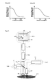
- the frame number at which the brightness value has the peak is f
- the frame number f becomes smaller as the functional depression rate of the mitochondria 41 becomes faster, and larger as the functional depression rate of the mitochondria 41 becomes slower.
- the functional depression rate was slowed by reducing the power of the excitation light source 11, with the other conditions held constant.
- the frame number f increased, as shown in Fig. 5(B) .
- Step S3 Process for Calculating Evaluating Value
- the CPU 22 calculates a frame number f (50 in Fig. 5(A) ) at which the brightness value of the reference point 40P has the peak, as shown by the arrow in Fig. 5(A) . Based on this frame number f, the CPU 22 calculates an evaluating value E of phototoxic property.
- Step S4 Process for Displaying Evaluating Value
- the system evaluates phototoxic property through repeated imaging of the specimen 1 7 performed by the main body of microscope 10.
- the evaluation is performed based on brightness changes ( Fig. 5 ) at the adjacent site (here, the cellular cytoplasm 43) of the stained site (here, the mitochondria 41), which is referred to instead of the brightness changes at the stained site.
- This evaluation yields proper results because the brightness changes at the adjacent site (here, the cellular cytoplasm 43) are well correlated with the functional depression at the stained site (here, the mitochondria 41), as described above.
- the evaluating value E accurately reflects the chromogenic rate of the adjacent site (here, the cellular cytoplasm 43) or the functional depression rate of the stained site (here, the mitochondria 41). That is, the evaluating value E is an accurate indication of phototoxic property.
- Fig. 6(A) and Fig. 6(B) show brightness changes at the stained site (here, the mitochondria 41).
- Fig. 6(A) represents a graph obtained with the excitation light source 11 held at high power
- FIG. 6(B) represents a graph obtained with the excitation light source 11 held at low power. As shown in Fig. 6(A) and Fig. 6(B) , the brightness change curves obtained from the stained site (here, the mitochondria 41) at different power levels of the excitation light source 11 have the peaks at the same point (frame number 1). It is therefore difficult to calculate an evaluating value of phototoxic property from these brightness change curves.
- the evaluating value of phototoxic property calculated from this brightness change curve would not be as accurate as the evaluating value E obtained in this embodiment.
- the mathematical formula deriving the evaluating value E from the frame number f be appropriately formulated such that the actual phototoxic property and the evaluating value E are linearly related to each other. This is possible by experiments or simulations using systems including the living cell in which the phototoxic property is known.
- the evaluating value E of phototoxic property is defined by the frame number f at the peak brightness value.
- the evaluating value E may be defined by the brightness value (peak brightness value) when the brightness has the peak.
- the evaluating value E may also be defined by both the frame number f and the peak brightness value.
- the irradiation of a laser beam from the excitation light source 11 be stopped or the intensity of the laser beam be reduced immediately after the brightness value of the reference point 40P has reached the peak and starts to decline, or after a predetermined period of time (several seconds) has elapsed from such an event.
- the system uses a confocal microscope as the main body of microscope 10, a plurality of fluorescence images with different sectionings can be obtained. Such multiple fluorescence images can be used to improve the accuracy of evaluating value E.
- the present embodiment has been described through the case where the stained site is mitochondria 41; however, other organelles or the area outside of the cell membrane (culture fluid) may be used as the stained site.
- the stained site is the cell nucleus
- the reference point may be set on the cellular cytoplasm 43.
- the reference point may be set on the culture fluid.
- the reference point may be set on the cellular cytoplasm 43. In any case, the reference point is set at a site adjacent to the stained site with a membrane in between.
- the marker may be an arbitrarily-shaped frame, such as a closed and free curved frame or a closed and multiangular shaped frame, that is displayed to exclude the stained area 44A (mitochondria 41) from the area including the stained area 44A and the cellular cytoplasm 43 adjacent thereto ( Fig. 4(B) ).
- the area defined by the annular frame is the reference point 40P.
- the arbitrarily-shaped frame defining the reference point 40P may be variable in size.
- the main body of microscope 10 of the system which has been described as a microscope that obtains fluorescence images, may be modified to obtain both fluorescence images and differential interference images.
- the differential interference image may be superimposed on the fluorescence image displayed on the monitor 30.
- the superimposed differential interference image allows for observation of non-fluorescing organelles (transparent organelles).
- the differential interference image can be used to set the reference point. In this case, failure to set the reference point becomes less likely.
- the operating program for the CPU 22 has been described as being pre-stored in the hard disc drive 25.
- the program may be installed either partially or entirely in the computer 20 via, for example, the Internet or CD-ROM (not shown).
- the main body of microscope 10 of the system described as a confocal microscope that detects a confocal point of the light from the specimen 17, may omit this function.
- the pinhole mask 101 will not be required.
- the main body of microscope 10 may be modified to a multiphoton microscope that attains the confocal effect by methods other than using the pinhole mask.
- the main body of microscope 10 of the system which is a scanning microscope for scanning the specimen 1 7 with light, may be a non-scanning microscope when it omits the confocal point detecting function.
- the optical scanner 15 will not be required, and an imaging sensor is provided instead of the light sensor 102.
- the system is applicable to evaluation of cell function using a drug, by supplying a drug to the mitochondria 41 with the fluorescent dye. Further, the system is applicable to evaluation of cell function by heat or radiation, by applying heat or radiation with light.
- the therapeutic objective ST1 is, for example, an affected area including cancer cells, supplemented beforehand with a fluorescent dye for mitochondria (for example, RH123).
- the fluorescent dye is used for the evaluation of phototoxic property (evaluation of therapeutic effect).
- the therapeutic system ST2 irradiates the therapeutic objective ST1 with radiation rays (such as gamma rays) or laser light for therapy (ultraviolet range, visible range, infrared range), so as to induce cell injury or cell death in cancer cells.
- radiation rays such as gamma rays
- laser light for therapy ultraviolet range, visible range, infrared range
- the laser light for therapy is generated in a radiation device 51 provided in the therapeutic system ST2, and is emitted as pulsed oscillations toward the therapeutic objective ST1, from a tube tip (head) 52, measuring several millimeters to several centimeters in diameter, provided at the tip of the therapeutic system ST2.
- the head 52 is provided to improve the efficiency of concentrating the energy of the laser light for therapy onto the therapeutic objective ST1.
- the excitation system ST4 includes an excitation light source 11 and a dichroic mirror 13. Through an objective lens 16 of the observing system ST3, the excitation system ST4 emits excitation light (for example, a wavelength of 507 nm) as pulsed oscillations toward the therapeutic objective ST1. The excitation light is emitted alternately with the laser light for therapy.
- the observing system ST3 includes the objective lens 16, an image-forming lens 19, an imaging sensor 102', a circuit part 20', and a monitor 30, among others.
- the fluorescence generated in the therapeutic objective ST1 during the irradiation of the excitation light is captured by the objective lens 16 and the image-forming lens 19 of the observing system ST3, and a fluorescence image of the therapeutic objective ST1 is formed on the imaging sensor 102'.
- the imaging sensor 102' continuously captures the fluorescence images, which are then output to the monitor 30 one after another via the circuit part 20'.
- the imaging magnifications of the objective lens 16 and the image-forming lens 19 of the observing system ST3 are set to values suitable for the observation of microstructures (organelles) of the cells. Accordingly, cells 40 of the therapeutic objective ST1 are displayed in real time on the monitor 30.
- the head of the observing system ST3 and the excitation system ST4, and the head 52 of the therapeutic system ST2 are facing substantially the same point on the therapeutic objective ST1, so that the imaging point of the fluorescence image substantially coincides with the irradiation point of the laser light for therapy. To suppress any misregistration between the two, these heads may be fixed or the same head may be used.
- an operator observes the stained site (here, the mitochondria 41) and the adjacent site (here, the cellular cytoplasm 43) on the monitor 30 while the therapeutic objective ST1 is being irradiated with the laser light for therapy.
- the operator looks at the brightness of the adjacent site (here, the cellular cytoplasm 43) and evaluates the phototoxic property (therapeutic effect) of the therapeutic system ST2 according to the timing at which the brightness reaches the peak, or the extent of brightness when it has the peak. According to the result of evaluation, the operator suspends the irradiation of the laser light for therapy at an appropriate timing, or adjusts the power of the therapeutic system ST2 at an appropriate level.
- the system allows the operator to perform photodynamic therapy while evaluating the therapeutic effect in real time, making it possible to perform an appropriate therapy without failing to remove cancer tissues by underexposure of the laser light for therapy, or without causing any side effect by overexposure of the laser light for therapy.
- the brightness may be checked by automation.
- the circuit part 20' of the observing system ST3 extracts a brightness signal of the adjacent site (here, the cellular cytoplasm 43) from the output of the imaging sensor 102', and notifies the operator of the level of the brightness signal in real time.
- the notification may be given on the monitor 30, or by playing sounds from a separately provided sound output device (speaker).
- the excitation light and the light for therapy are separately provided in the system described above, the light for therapy may be used to also provide the excitation light, when it contains a wavelength component for the excitation light.
- the therapeutic apparatus described in this Second Embodiment can be made into a diagnostic apparatus simply by replacing the therapeutic system ST2 with a diagnostic system.
- the diagnostic system includes a diagnostic wave (sound wave, electromagnetic wave) generator, an illuminating optical system for illuminating the affected area, an imaging sensor, and an imaging optical system for condensing the reflected light from the illuminated affected area onto the imaging sensor.
- Fig. 8(A) is the actual first fluorescence image obtained. Predetermined positions of the mitochondria (stained area) and the cellular cytoplasm (reference point) were specified by rectangular shaped frames, and a mean value of brightness values of the pixels in each of these specific areas was determined. These mean values were used as the brightness value of the mitochondria, and the brightness value of the cellular cytoplasm, respectively. This procedure of obtaining the fluorescence image was repeated under the same conditions, and the brightness values of the mitochondria and the cellular cytoplasm were measured.
- Fig. 8(B) is the actual 50th fluorescence image
- Fig. 8(C) is the actual 150th fluorescence image obtained. It can be seen from Fig. 8 that the fluorescence image indeed undergoes changes as described in the First Embodiment with reference to Fig. 2 .
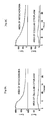
- Fig. 9(B) is the actual graph plotting the brightness values of the mitochondria and the cellular cytoplasm measured by the irradiation of a laser beam having a weaker intensity than the laser used in Fig. 9(A) .
- the brightness value of the cellular cytoplasm has the peak in frame number 70, showing that the functional depression of the mitochondria proceeds at a slower rate when the intensity of the excitation laser beam is weaker.
- An evaluating method of the present invention is applicable to evaluation of an illuminant such as a laser scanning confocal microscope (evaluation of device effectiveness), evaluation of drugs such as antioxidants (drug screening, etc.), and evaluation of fluorescent dye (evaluation of fluorescence lifetime), among others.
- an illuminant such as a laser scanning confocal microscope (evaluation of device effectiveness), evaluation of drugs such as antioxidants (drug screening, etc.), and evaluation of fluorescent dye (evaluation of fluorescence lifetime), among others.
Landscapes
- Health & Medical Sciences (AREA)
- Life Sciences & Earth Sciences (AREA)
- Immunology (AREA)
- Engineering & Computer Science (AREA)
- Chemical & Material Sciences (AREA)
- General Health & Medical Sciences (AREA)
- Pathology (AREA)
- Physics & Mathematics (AREA)
- Biomedical Technology (AREA)
- Analytical Chemistry (AREA)
- General Physics & Mathematics (AREA)
- Biochemistry (AREA)
- Nuclear Medicine, Radiotherapy & Molecular Imaging (AREA)
- Molecular Biology (AREA)
- Hematology (AREA)
- Veterinary Medicine (AREA)
- Public Health (AREA)
- Animal Behavior & Ethology (AREA)
- Urology & Nephrology (AREA)
- Biophysics (AREA)
- Surgery (AREA)
- Heart & Thoracic Surgery (AREA)
- Bioinformatics & Cheminformatics (AREA)
- Toxicology (AREA)
- Tropical Medicine & Parasitology (AREA)
- Biotechnology (AREA)
- Cell Biology (AREA)
- Medical Informatics (AREA)
- Microbiology (AREA)
- Radiology & Medical Imaging (AREA)
- Food Science & Technology (AREA)
- Medicinal Chemistry (AREA)
- Chemical Kinetics & Catalysis (AREA)
- Optics & Photonics (AREA)
- Signal Processing (AREA)
- Dispersion Chemistry (AREA)
- Investigating, Analyzing Materials By Fluorescence Or Luminescence (AREA)
- Investigating Or Analysing Biological Materials (AREA)
- Investigating Or Analysing Materials By The Use Of Chemical Reactions (AREA)
Applications Claiming Priority (2)
| Application Number | Priority Date | Filing Date | Title |
|---|---|---|---|
| JP2006098712A JP2007271503A (ja) | 2006-03-31 | 2006-03-31 | 細胞機能の評価方法、細胞機能の評価システム、蛍光顕微鏡システム、光治療方法、及び光治療システム |
| PCT/JP2007/000313 WO2007116582A1 (ja) | 2006-03-31 | 2007-03-28 | 細胞機能の評価方法、細胞機能の評価システム、蛍光顕微鏡システム、光治療方法、及び光治療システム |
Publications (3)
| Publication Number | Publication Date |
|---|---|
| EP2003442A2 EP2003442A2 (de) | 2008-12-17 |
| EP2003442A9 true EP2003442A9 (de) | 2009-04-22 |
| EP2003442A4 EP2003442A4 (de) | 2009-06-17 |
Family
ID=38580884
Family Applications (1)
| Application Number | Title | Priority Date | Filing Date |
|---|---|---|---|
| EP07736970A Withdrawn EP2003442A4 (de) | 2006-03-31 | 2007-03-28 | Verfahren zur beurteilung der zellfunktion, system zur beurteilung der zellfunktion, fluoreszenzmikroskopsystem, lichttherapieverfahren und lichttherapiesystem |
Country Status (4)
| Country | Link |
|---|---|
| US (1) | US20090042238A1 (de) |
| EP (1) | EP2003442A4 (de) |
| JP (1) | JP2007271503A (de) |
| WO (1) | WO2007116582A1 (de) |
Families Citing this family (4)
| Publication number | Priority date | Publication date | Assignee | Title |
|---|---|---|---|---|
| JP5040597B2 (ja) * | 2007-11-06 | 2012-10-03 | 日本電気株式会社 | 評価システム、評価方法および評価プログラム |
| JP5719159B2 (ja) * | 2010-03-15 | 2015-05-13 | ソニー株式会社 | 評価装置 |
| US20170016911A1 (en) * | 2014-03-24 | 2017-01-19 | Konica Minolta, Inc. | Method for quantifying biological material based on multiple immunostaining |
| CN104215618A (zh) * | 2014-09-22 | 2014-12-17 | 上海交通大学 | 基于纳米金聚散淬灭罗丹明b荧光的银离子检测方法 |
Family Cites Families (2)
| Publication number | Priority date | Publication date | Assignee | Title |
|---|---|---|---|---|
| JPH07190936A (ja) * | 1993-12-27 | 1995-07-28 | Terumo Corp | 光毒性物質の測定方法 |
| JP2001004542A (ja) | 1999-06-24 | 2001-01-12 | Hamamatsu Photonics Kk | 一重項酸素検出装置とこれを用いた光線力学的治療装置 |
-
2006
- 2006-03-31 JP JP2006098712A patent/JP2007271503A/ja active Pending
-
2007
- 2007-03-28 EP EP07736970A patent/EP2003442A4/de not_active Withdrawn
- 2007-03-28 WO PCT/JP2007/000313 patent/WO2007116582A1/ja not_active Ceased
-
2008
- 2008-09-03 US US12/230,672 patent/US20090042238A1/en not_active Abandoned
Also Published As
| Publication number | Publication date |
|---|---|
| WO2007116582A1 (ja) | 2007-10-18 |
| US20090042238A1 (en) | 2009-02-12 |
| EP2003442A2 (de) | 2008-12-17 |
| EP2003442A4 (de) | 2009-06-17 |
| JP2007271503A (ja) | 2007-10-18 |
Similar Documents
| Publication | Publication Date | Title |
|---|---|---|
| KR102068776B1 (ko) | 자가형광이 존재하는 생물학적 물질에서 타겟 형광체의 이미징 | |
| US9687190B2 (en) | Intra-operative use of fluorescence spectroscopy and applications of same | |
| US11202918B2 (en) | Eye treatment system | |
| US20150042954A1 (en) | System and Method for Fluorescence Lifetime Imaging Aided by Adaptive Optics | |
| JP2013515266A (ja) | 目標の癌組織を視覚化する励起/検出/投射システム | |
| EP2003442A2 (de) | Verfahren zur beurteilung der zellfunktion, system zur beurteilung der zellfunktion, fluoreszenzmikroskopsystem, lichttherapieverfahren und lichttherapiesystem | |
| GB2254417A (en) | Photodynamic laser detection for cancer diagnosis | |
| EP2395381A1 (de) | Beobachtungsvorrichtung und Beobachtungsverfahren | |
| US20130053699A1 (en) | Apparatus and method for performing photodynamic diagnosis and photodynamic therapy | |
| WO2021009205A2 (en) | Method and system for electromagnetic spectroscopy of a sample | |
| JP2011185843A (ja) | 蛍光寿命を利用した細胞内のpHイメージング方法とその装置 | |
| CN113933271B (zh) | 一种活体荧光寿命成像光学系统和方法 | |
| KR101894150B1 (ko) | 다광자 특성을 이용한 안과용 진단 및 치료장치 | |
| US7983466B2 (en) | Microscope apparatus and cell observation method | |
| JP4184228B2 (ja) | 蛍光寿命測定装置 | |
| Muriello et al. | Improving signal levels in intravital multiphoton microscopy using an objective correction collar | |
| JP2022122181A (ja) | 補正パラメータ設定方法及びデータ補正方法 | |
| CN1119972C (zh) | 共轴微光—荧光肺癌诊断和定位仪器 | |
| JP2004271215A (ja) | 蛍光検出装置 | |
| RU2788118C1 (ru) | Способ дистанционного мониторинга растительности с бпла и устройство для его осуществления | |
| JPH08280692A (ja) | 医療用レーザ診断装置 | |
| Zhu et al. | Combined two-photon calcium imaging and single-ommatidium visual stimulation to study fine-scale retinotopy in insects | |
| CN121453733A (zh) | 一种荧光病理切片扫描系统、方法以及装置 | |
| JP5599184B2 (ja) | 酵素活性測定方法、酵素活性測定装置及び酵素活性測定プログラム | |
| Kłonowski et al. | Scanning setup for the investigation of fluorescence beam spectra |
Legal Events
| Date | Code | Title | Description |
|---|---|---|---|
| PUAI | Public reference made under article 153(3) epc to a published international application that has entered the european phase |
Free format text: ORIGINAL CODE: 0009012 |
|
| 17P | Request for examination filed |
Effective date: 20080901 |
|
| AK | Designated contracting states |
Kind code of ref document: A2 Designated state(s): AT BE BG CH CY CZ DE DK EE ES FI FR GB GR HU IE IS IT LI LT LU LV MC MT NL PL PT RO SE SI SK TR |
|
| PUAB | Information related to the publication of an a document modified or deleted |
Free format text: ORIGINAL CODE: 0009199EPPU |
|
| RIC1 | Information provided on ipc code assigned before grant |
Ipc: G01N 33/50 20060101ALI20090507BHEP Ipc: G01N 1/30 20060101ALI20090507BHEP Ipc: G01N 1/28 20060101ALI20090507BHEP Ipc: G01N 21/64 20060101AFI20080107BHEP |
|
| A4 | Supplementary search report drawn up and despatched |
Effective date: 20090515 |
|
| 17Q | First examination report despatched |
Effective date: 20090910 |
|
| RAP1 | Party data changed (applicant data changed or rights of an application transferred) |
Owner name: SAKURAI, TAKASHI Owner name: NIKON CORPORATION |
|
| STAA | Information on the status of an ep patent application or granted ep patent |
Free format text: STATUS: THE APPLICATION IS DEEMED TO BE WITHDRAWN |
|
| 18D | Application deemed to be withdrawn |
Effective date: 20120113 |