EP2003362B1 - Elément de ressort en élastomère précontaint de manière hydraulique et son utilisation dans des supports d'éoliennes - Google Patents
Elément de ressort en élastomère précontaint de manière hydraulique et son utilisation dans des supports d'éoliennes Download PDFInfo
- Publication number
- EP2003362B1 EP2003362B1 EP08010491.2A EP08010491A EP2003362B1 EP 2003362 B1 EP2003362 B1 EP 2003362B1 EP 08010491 A EP08010491 A EP 08010491A EP 2003362 B1 EP2003362 B1 EP 2003362B1
- Authority
- EP
- European Patent Office
- Prior art keywords
- membrane
- spring element
- pressure
- space
- hydraulic
- Prior art date
- Legal status (The legal status is an assumption and is not a legal conclusion. Google has not performed a legal analysis and makes no representation as to the accuracy of the status listed.)
- Active
Links
- 239000012528 membrane Substances 0.000 claims description 235
- 229920001971 elastomer Polymers 0.000 claims description 80
- 239000000806 elastomer Substances 0.000 claims description 79
- 239000011324 bead Substances 0.000 claims description 50
- 238000006073 displacement reaction Methods 0.000 claims description 36
- 239000012530 fluid Substances 0.000 claims description 29
- 239000000463 material Substances 0.000 claims description 23
- 238000007789 sealing Methods 0.000 claims description 12
- 230000006835 compression Effects 0.000 claims description 5
- 238000007906 compression Methods 0.000 claims description 5
- 238000009434 installation Methods 0.000 claims description 5
- 239000013013 elastic material Substances 0.000 claims description 3
- 230000015572 biosynthetic process Effects 0.000 claims description 2
- 239000010410 layer Substances 0.000 claims 12
- 239000011229 interlayer Substances 0.000 claims 3
- 210000004379 membrane Anatomy 0.000 description 192
- 230000005540 biological transmission Effects 0.000 description 13
- 230000036316 preload Effects 0.000 description 11
- 238000003860 storage Methods 0.000 description 11
- 238000013016 damping Methods 0.000 description 10
- 239000007788 liquid Substances 0.000 description 9
- 239000013536 elastomeric material Substances 0.000 description 6
- 238000005452 bending Methods 0.000 description 5
- 230000009467 reduction Effects 0.000 description 5
- 244000043261 Hevea brasiliensis Species 0.000 description 4
- 238000010276 construction Methods 0.000 description 4
- 239000002184 metal Substances 0.000 description 4
- 229920003052 natural elastomer Polymers 0.000 description 4
- 229920001194 natural rubber Polymers 0.000 description 4
- 238000004073 vulcanization Methods 0.000 description 4
- 230000008901 benefit Effects 0.000 description 3
- 235000015095 lager Nutrition 0.000 description 3
- 239000004033 plastic Substances 0.000 description 3
- 229920003023 plastic Polymers 0.000 description 3
- 239000011148 porous material Substances 0.000 description 3
- 241000196324 Embryophyta Species 0.000 description 2
- 150000001298 alcohols Chemical class 0.000 description 2
- 239000011230 binding agent Substances 0.000 description 2
- 230000008878 coupling Effects 0.000 description 2
- 238000010168 coupling process Methods 0.000 description 2
- 238000005859 coupling reaction Methods 0.000 description 2
- 230000000694 effects Effects 0.000 description 2
- 239000000203 mixture Substances 0.000 description 2
- XLYOFNOQVPJJNP-UHFFFAOYSA-N water Substances O XLYOFNOQVPJJNP-UHFFFAOYSA-N 0.000 description 2
- 229920000049 Carbon (fiber) Polymers 0.000 description 1
- 241001295925 Gegenes Species 0.000 description 1
- 238000005299 abrasion Methods 0.000 description 1
- 239000000654 additive Substances 0.000 description 1
- 239000000853 adhesive Substances 0.000 description 1
- 230000001070 adhesive effect Effects 0.000 description 1
- 230000002528 anti-freeze Effects 0.000 description 1
- TZCXTZWJZNENPQ-UHFFFAOYSA-L barium sulfate Chemical compound [Ba+2].[O-]S([O-])(=O)=O TZCXTZWJZNENPQ-UHFFFAOYSA-L 0.000 description 1
- 230000033228 biological regulation Effects 0.000 description 1
- 230000009172 bursting Effects 0.000 description 1
- 239000004917 carbon fiber Substances 0.000 description 1
- 230000008859 change Effects 0.000 description 1
- 238000004891 communication Methods 0.000 description 1
- 239000002131 composite material Substances 0.000 description 1
- 230000007423 decrease Effects 0.000 description 1
- 238000010586 diagram Methods 0.000 description 1
- 239000000428 dust Substances 0.000 description 1
- 238000005516 engineering process Methods 0.000 description 1
- 238000007667 floating Methods 0.000 description 1
- 239000010720 hydraulic oil Substances 0.000 description 1
- 238000002955 isolation Methods 0.000 description 1
- 238000004519 manufacturing process Methods 0.000 description 1
- 230000005226 mechanical processes and functions Effects 0.000 description 1
- VNWKTOKETHGBQD-UHFFFAOYSA-N methane Chemical compound C VNWKTOKETHGBQD-UHFFFAOYSA-N 0.000 description 1
- 230000005012 migration Effects 0.000 description 1
- 238000013508 migration Methods 0.000 description 1
- 239000003921 oil Substances 0.000 description 1
- 230000000149 penetrating effect Effects 0.000 description 1
- 230000035515 penetration Effects 0.000 description 1
- 238000002360 preparation method Methods 0.000 description 1
- 238000003825 pressing Methods 0.000 description 1
- 238000005096 rolling process Methods 0.000 description 1
- 239000007787 solid Substances 0.000 description 1
- 210000002023 somite Anatomy 0.000 description 1
Images


Classifications
-
- F—MECHANICAL ENGINEERING; LIGHTING; HEATING; WEAPONS; BLASTING
- F16—ENGINEERING ELEMENTS AND UNITS; GENERAL MEASURES FOR PRODUCING AND MAINTAINING EFFECTIVE FUNCTIONING OF MACHINES OR INSTALLATIONS; THERMAL INSULATION IN GENERAL
- F16F—SPRINGS; SHOCK-ABSORBERS; MEANS FOR DAMPING VIBRATION
- F16F1/00—Springs
- F16F1/36—Springs made of rubber or other material having high internal friction, e.g. thermoplastic elastomers
- F16F1/40—Springs made of rubber or other material having high internal friction, e.g. thermoplastic elastomers consisting of a stack of similar elements separated by non-elastic intermediate layers
-
- F—MECHANICAL ENGINEERING; LIGHTING; HEATING; WEAPONS; BLASTING
- F03—MACHINES OR ENGINES FOR LIQUIDS; WIND, SPRING, OR WEIGHT MOTORS; PRODUCING MECHANICAL POWER OR A REACTIVE PROPULSIVE THRUST, NOT OTHERWISE PROVIDED FOR
- F03D—WIND MOTORS
- F03D80/00—Details, components or accessories not provided for in groups F03D1/00 - F03D17/00
- F03D80/70—Bearing or lubricating arrangements
-
- F—MECHANICAL ENGINEERING; LIGHTING; HEATING; WEAPONS; BLASTING
- F16—ENGINEERING ELEMENTS AND UNITS; GENERAL MEASURES FOR PRODUCING AND MAINTAINING EFFECTIVE FUNCTIONING OF MACHINES OR INSTALLATIONS; THERMAL INSULATION IN GENERAL
- F16F—SPRINGS; SHOCK-ABSORBERS; MEANS FOR DAMPING VIBRATION
- F16F13/00—Units comprising springs of the non-fluid type as well as vibration-dampers, shock-absorbers, or fluid springs
- F16F13/04—Units comprising springs of the non-fluid type as well as vibration-dampers, shock-absorbers, or fluid springs comprising both a plastics spring and a damper, e.g. a friction damper
- F16F13/06—Units comprising springs of the non-fluid type as well as vibration-dampers, shock-absorbers, or fluid springs comprising both a plastics spring and a damper, e.g. a friction damper the damper being a fluid damper, e.g. the plastics spring not forming a part of the wall of the fluid chamber of the damper
- F16F13/08—Units comprising springs of the non-fluid type as well as vibration-dampers, shock-absorbers, or fluid springs comprising both a plastics spring and a damper, e.g. a friction damper the damper being a fluid damper, e.g. the plastics spring not forming a part of the wall of the fluid chamber of the damper the plastics spring forming at least a part of the wall of the fluid chamber of the damper
-
- F—MECHANICAL ENGINEERING; LIGHTING; HEATING; WEAPONS; BLASTING
- F05—INDEXING SCHEMES RELATING TO ENGINES OR PUMPS IN VARIOUS SUBCLASSES OF CLASSES F01-F04
- F05B—INDEXING SCHEME RELATING TO WIND, SPRING, WEIGHT, INERTIA OR LIKE MOTORS, TO MACHINES OR ENGINES FOR LIQUIDS COVERED BY SUBCLASSES F03B, F03D AND F03G
- F05B2240/00—Components
- F05B2240/50—Bearings
-
- F—MECHANICAL ENGINEERING; LIGHTING; HEATING; WEAPONS; BLASTING
- F16—ENGINEERING ELEMENTS AND UNITS; GENERAL MEASURES FOR PRODUCING AND MAINTAINING EFFECTIVE FUNCTIONING OF MACHINES OR INSTALLATIONS; THERMAL INSULATION IN GENERAL
- F16F—SPRINGS; SHOCK-ABSORBERS; MEANS FOR DAMPING VIBRATION
- F16F2228/00—Functional characteristics, e.g. variability, frequency-dependence
- F16F2228/08—Functional characteristics, e.g. variability, frequency-dependence pre-stressed
Definitions
- the invention relates to spring elements and bearings which contain these spring element, wherein the spring stiffness of the bearing or spring elements can be adjusted individually by biasing elastomeric bodies or elastomer layers.
- the deformation of the elastomer layers and thus the spring elements is achieved by a correspondingly designed hydraulic device.
- the tightness of the spring or bearing elements according to the invention is achieved by special hydraulically pre-stressed sealing elements, use of a pressure membrane and special structural features of the elastomer elements.
- the elastomeric bearings according to the invention including their spring elements are particularly suitable for use in two- or multi-point bearings in rotor and gearbox designs of large wind turbines and serve there to absorb damping and driveline vibrations, which in particular lead to displacement, bending and deformation forces and especially in extreme Stress situations of the plant can occur.
- Elastic spring elements are known and are used in many areas of technology primarily for damping vibrations and forces.
- the spring element has a defined by the type, size, shape and number of existing elastomer layers defined stiffness, which may optionally be made variable after installation of the spring element in a certain frame.
- the driveline of wind turbines is usually attached elastically to the machine frame. This is done for reasons of structure-borne sound isolation and also to allow shifts in the system.
- the known bearings are equipped with passive elastic elements which can cushion at least part of such constraining forces and vibrations generated due to their orientation and different preset stiffnesses.
- the storage can be done as described by two bearings or by a large moment bearing, which causes the same mechanical function.
- the torque is supported on both sides of the transmission according to the prior art.
- the disadvantage with this system is the indefinite storage resulting from four storage points. Due to this indefinite storage constraining forces occur, which may have the following causes: manufacturing and assembly tolerances, misalignment, skew on the rotor shaft and the gearbox flange and last but not least the bending of all supporting elements to each other in unsymmetrical force guide by the rotor. On the rotor occur in addition to the drive torque in addition to other moments. These arise, for example, as a result of uneven wind flow or due to the passing of the rotor blade on the tower.
- an elastomeric bearing for wind turbines with adjustable stiffness in which the elastomer elements in said vertical direction in their rigidity by a hydraulic or mechanical device can be changed.
- These spring elements essentially comprise a connection plate and an end plate between which there is at least one elastomer layer, wherein the connection plate has an opening with a connection part through which pressure can be exerted on the elastomer layer with a displacement element in the form of a hydraulic fluid or a movable piston element, whereby a bias increase of the spring element and thus a stiffening in the vertical direction is achieved.
- the invention thus provides a spring element which can be adjusted in its rigidity by hydraulically generated pressure and which comprises layers comprising essentially two or more elastomer layers (1), inelastic intermediate layers (2), one or more hydraulic devices including sealing elements (4, 7, 9, 11 , 12) and optionally inelastic end plates, wherein two elastomer layers are separated by an inelastic intermediate layer or plate, and the inelastic layers have a centrally disposed opening or bore, so that the spring element at least in the interior has a continuous elastomeric core, with the Elastomer layers are connected, wherein - seen in the vertical direction to the layers - on one or both sides of the spring element said hydraulic device is provided which by displacement or introduction of a hydraulic fluid by means of hydraulic pressure in the spring element causes the compression of the elastomeric material (1) in the core region thereof in the vertical direction to the layers, so that a displacement space is created or increased.
- said spring element is characterized in that between the elastomer layer in the core region of the spring element and the displacement chamber an elastic pressure membrane (5) is arranged, which is firmly connected at its preferably outer edge with the hydraulic device or parts thereof, so that a membrane space (12) is formed, which corresponds at least in the presence of a hydraulic pressure to the displacement chamber and contains hydraulic fluid, and the hydraulic device comprises one or more sealing elements, which have a bias and are arranged so that they on the pressure membrane in the region Connection to the hydraulic device to generate an increased pressure against the pressure in the membrane space, whereby the solid connection to the hydraulic fluid-containing membrane space is absolutely pressure-tight even at very high pressures in the interior of the membrane space.
- the term "displacement space” is understood to mean the space which is created by introducing a hydraulic fluid into the spring element to generate a hydraulic pressure by compressing elastomer material or possibly already exists.
- “membrane space” (12) is understood to mean the geometric space formed between the membrane plate (9) and the pressure membrane (5) stretched over it. As a rule, under pressure, the membrane space essentially corresponds to the displacement space.
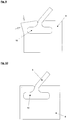
- the invention relates in particular to a corresponding spring element, in which the elastic pressure membrane (5) rests on a diaphragm belonging to the hydraulic device (9), and at its edge with this via an elastic bead (10), the T-groove shaped Recess (10a) in the membrane plate fills, is connected, and an inelastic pressure increasing element (6), preferably a profile ring, between the elastomer layer (1) and the pressure membrane in the region of its bead is arranged, which has a correspondingly shaped profile which, when prestressed, which has to correspond to a higher pressure than the pressure in the membrane space (12), is pressed into the elastic material in the region of the bead of the pressure membrane, and thus leads to a targeted sealing in the T-groove of the membrane plate.
- an inelastic pressure increasing element (6) preferably a profile ring
- the seal is particularly advantageous, stable and complete when between the pressure increasing element (6) and elastic bead (10) of the pressure membrane, a preload clearance (10c) is provided by a corresponding, preferably wedge-shaped recess in the material the sealing elements or the corresponding parts of the hydraulic device can be formed.
- the pressure-increasing element (6) for example the profile ring, is dispensed with and functionally replaced by the membrane plate (9), which in this case, however, is compressed in the region of the T-slot, so that increased pressure occurs locally , which leads to a stronger seal in this area ( Fig.9 ).
- the membrane is typically a circular membrane which rests flat on the membrane plate (9).
- the membrane is inflated, whereby a compression of lying on the other side of the membrane elastomer layers (1) is effected and between the membrane plate (9) and the membrane, a displacement or membrane space is formed ( Fig. 6 ).
- the membrane plate (9) has a concavely curved surface, so that when the pressure membrane (5) is stretched even without a pressure generated there is a membrane space which is formed between the underside of the flat membrane and the concave surface of the membrane plate ( Fig. 7, 8 ).
- the elastomer layer (1) may also have a concavely curved recess in the region of the contact surface with the pressure membrane (5).
- both the membrane plate (9) and the elastomer layer lying over the pressure membrane have a corresponding concave surface, so that there is a lenticular membrane or displacement space.
- the invention also provides a corresponding spring element, in which the membrane plate (9) has hydraulic supply lines (4) and connections (7) which pass through the membrane plate and open into the membrane space and can supply it with hydraulic fluid.
- these have a carrier plate (11) for the elastomer layers (1), which preferably have a recess in which the membrane plate (9) finds room as a separate part of the carrier plate.
- the membrane plate against the support plate itself be braced.
- the invention further spring elements are the same principle as described, but have special design features due to their space-saving manner.
- the invention comprises a spring element, wherein the elastic pressure membrane (5) has a circumferential end elastic T-shaped bead (10) consisting of an outer (26) and inner bead (23), and having a belonging to the hydraulic device Membrane plate (9) is connected in a pressure-tight manner in such a way that said beads are inserted into a correspondingly shaped matching T-shaped hollow profile (10 b), which is formed by a correspondingly shaped diaphragm head (9 a) and a biasing disc (21), wherein (a ) the membrane head is a part of the membrane plate (9) and is disposed within the membrane and the membrane space (12) and has a circumferential protruding lip (24) which receives the inner bead (23) of the membrane, and (b) the biasing plate a ring-like opening or recess which receives the membrane head (9a) with the pressure diaphragm
- the biasing disc (21) is wholly or partially on the membrane plate (9) except the region of the membrane head (9a) and is disposed between the first elastomer layer (1) or possibly the elastomer support plate and said membrane plate. In this case, preferably, the biasing disc (21) with the elastomer layers (1) outside the region of the pressure membrane is firmly connected.
- the membrane disc (9) is braced against the biasing disc (21) by means of fastening means, so that the T-shaped elastic bead (23, 26) of the pressure membrane is compressed.
- the pretensioning disk or plate (21) can also be a support plate for the spring element itself, wherein in this embodiment it has a precisely fitting recess in the area of the pressure membrane into which the correspondingly shaped membrane plate (9) with its correspondingly shaped membrane head (9a) is inserted and is clamped to the plate (21) by means of fastening means.
- the membrane plate (9) at least one hydraulic inlet and outlet (4, 7), wherein the hydraulic inlet through the membrane head (9a) leads and opens in the membrane space (12).
- the spring elements which occupy a smaller space, preferably have a preload space (22) which is formed in the untensioned state in the area in which outer bead (26), membrane disc (9) and biasing disc (21) meet, and the when bracing the parts (21) and (9) by pressing in bead material completely closes.
- the elastic pressure membrane (5) according to the invention should according to the invention have a certain softness and flexibility.
- Such membranes are preferably suitable for spring element according to the invention, in which a large footprint is necessary or desirable.
- the cone-shaped or parboloid membranes which are preferably used in stiffer and less flexible but elastic in terms of elongation.
- the invention thus also relates to such spring elements in which the pressure membrane (5) is stiff and has a parabolic or conical spatial shape, which with the membrane head (9a) located at the base, a correspondingly shaped cone-hat-like membrane cavity (12) or a cone cone hat ( 12a) forms.
- the invention also relates in particular to corresponding spring elements in which the elastomer layers (1) in the core of the spring element have a cone-shaped cavity correspondingly shaped to the membrane cavity (12), which is filled by the membrane cone cap (12a) formed by the pressure membrane.
- Such spring elements may be modified in such a way that the membrane cavity (12) of the Druckmembrankegelhuts (12a) has a stop device (50) which prevents overloading the system that the conical pressure membrane irreversibly collapses.
- a stop device is made of an inelastic material is preferably made in the form of a conical hat, which is centrally located in the interior of the membrane cavity (12) on the base of the membrane head (12a) and a Zulauf arrangement and a connection to the hydraulic supply line (4).
- the feed guide can also be designed in the form of an annular gap.
- the described hydraulic devices including pressure diaphragms and sealing elements can be mounted on both (the upper and lower) sides of the spring element.
- Such spring elements are particularly suitable if they must be very large, so that a pressure generated on one side can be unfavorable. In most cases, it is sufficient if the spring element is equipped only on one side with a corresponding device.
- such a spring element may be equipped such that it has on the side opposite the hydraulic device in the core region of the spring element a recess or cavity (40) in the elastomeric material which is shaped and configured to / it is separated from the diaphragm space (12) by means of a web (42) made of elastomeric material of the layers (1), so that the web can be pressed into the cavity or recess when the hydraulic pressure in the diaphragm space is increased.
- a greater variability of the adjustability of the rigidity is possible, in particular if the recess or the cavity (40) additionally has an inelastic calibration element (3, 8) with the aid of which the volume of the recess or of the cavity (4) can change.
- the described spring elements are ideally suited to be used as bearings for machines or transmissions.
- the invention thus relates to a bearing comprising at least two opposing identically aligned or arranged and thus with respect to their damping properties the same acting spring elements between which the gear or the machine is fixed, as described above, below and in the claims.
- the spring elements according to the invention are interconnected by crosswise arranged hydraulic lines (34, 35), whereby the bearings receive the properties described further.
- they can be equipped with at least one overpressure valve (31) and one throttle valve (33, 36, 37) for targeted control in systems under load, as also explained below.
- the invention is ultimately the use of the described bearing or spring element. These are intended for use in machines, but especially wind turbines, and serve here for cushioning bending, deformation and displacement forces, which occur especially in extreme load case in the vertical direction to the mounted spring elements.
- the elastomeric materials used for the layers (1) according to the invention consist essentially of a natural rubber, a natural rubber derivative or of a suitable elastic polymeric plastic or plastic mixture.
- the elastomer layer according to the invention may have different hardness ("shore hardness") and different damping properties, according to the desired requirements.
- elastomers having a hardness of 20 to 100 Shore A, in particular 30 used up to 80 Shore A are known in the art and adequately described in the relevant literature.
- the non-elastomeric intermediate plates or layers (2) are made according to the invention of largely inelastic materials with low compressibility.
- these are metal sheets, but other materials such as hard plastics, composites or carbon fiber-containing materials are used.
- the intermediate sheets and the elastomeric materials (4) are usually bonded together by vulcanization.
- the pressure membrane (5) is usually also made of natural rubber or a natural rubber derivative.
- the material must be tear and pressure resistant over a large area. It is preferably of a smooth, dense structure which has no surface pores or only very small diameter pores which are incapable of receiving microdroplets of the hydraulic fluid.
- hydraulic fluids can be used as hydraulic fluids.
- water which optionally buried antifreeze, alcohols or additives, suitable.
- hydraulic oils can be used.
- the spring element according to the invention can be used in two basic structural embodiments.
- the first embodiment is based on a flat membrane (5) occupying a relatively large area on the membrane plate (9).
- the displacement chamber, or membrane space (5) is formed above all by the inflation of the membrane lying flat on the membrane plate with simultaneous compression of the elastomer layers (1) above the pressure membrane.
- Recesses, preferably concave type, in the elastomer layer above the membrane and / or in the membrane plate (9) below the membrane can generate a displacement space already in the unpressurized state.
- the flat membrane ( Fig. 6 ) has a relatively flat, preferably lenticular shape
- the second principal embodiment is represented by the parabolic membrane or conical membrane ( Fig. 11 - 19 ), which already in the pressureless state, the said conical shape or a paraboloid.
- the membrane provides a sealing function between the fluid and the elastomeric body.
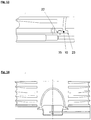
- Fig. 6 and FIGS. 11-19 represent an elastomer component with a plurality of layers (eg 4 layers).
- the special feature over conventional layer springs is that the preferably round intermediate plates (2) have a preferably central bore so that the inelastic structure is present only in the outer region.
- the core region In the inner region, the core region, only elastomer (1) is present, which preferably has a recess in has the area occupied by the membrane surface.
- the spring elements according to the invention comprise a membrane plate (9) which contains an opening for the connection of the hydraulic lines. Furthermore, the membrane plate contains an annular T-slot (10) into which the surface membrane (5) is vulcanized. In the vulcanization is the peculiarity that only in the T-groove binding occurs. The remaining area remains without bond, so that here a cavity for introducing the hydraulic medium in the membrane space (12) is formed. According to the tightness of the T-shaped connection is very important. In the prior art, this is achieved on the one hand by applying a binder into the T-groove before vulcanization, so that a rubber-metal compound is formed. This rubber-metal compound should be absolutely tight according to the prior art.
- a simple variant dispenses with its own pressure-increasing ring.
- the T-shaped groove is introduced into the membrane plate (9) and vulcanized. Thereafter, the outer region of the membrane plate is bent inwardly, thereby increasing the pressure in the region of the T-slot (10) takes place and tightness is ensured.
- This bias is about 10% to 40% of the thickness of the outer bead (26), so that a part of the volume of the outer bead is displaced to the inner bead (23), so that here also creates a bias and thus the tightness of the bead is reached.
- the outer bead (26) shifts to both sides when biased and thus pushes between the biasing ring (21) and the diaphragm plate (9) before they come together and close the gap.
- the outer bead (26) between the biasing ring (21) and diaphragm (9) would pinch.
- a preferably wedge-shaped preload clearance (22) is provided.
- This preload clearance is about 2 - 3 mm deep, ie deeper than the material flows under the given bias, so that here an undefined clamping of the elastomer from the outer bead (26) is prevented.
- the clamping can be done without additional medium.
- spring elements based on a parabolic membrane pressures of 200 to 1500 are provided due to the smaller size. The diaphragm can withstand this pressure only if it is guided cleanly and in all places into the conical cavity of the elastomer component and does not get in contact with the hard intermediate plates.
- a minimum distance (28) to the intermediate plates (2) is required. This should be at least 5 mm.
- the bias between membrane plate (9) and bias plate (21) can also be reversed so that the inner bead clamping portion of (9) is separated and can be tightened by screws ( Fig. 14 ). Again, a bias clearance (22) should be provided.
- the built-in wind turbine spring element, or such elements containing bearings work in relation to the damping of the system as follows:
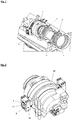
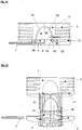
- the transmission has on both sides of a transmission-side torque arm (11) on ( Fig. 1, 2 ). This will entwined with a yoke (10).
- a yoke (10) Between the transmission-side torque arm (11) and the yoke (10) elastomer elements (06, 07, 08 and 09) are arranged.
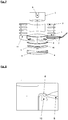
- the elastomeric elements contain a cavity which is filled with liquid. These cavities, respectively, are as in Fig. 3, 4 shown, with Hydraulikleitunegn (34, 35), which may be pipes or hoses, connected together.
- Hydraulikleitunegn 34, 35
- Both are connected to each other with the hydraulic line (34) so that no fluid movement takes place due to the pressure which arises at the same time.
- the elastomer elements (07, 09) are simultaneously relieved, so that even in the hydraulic line (35) no hydraulic fluid is moved.
- the springs thus show a stiff spring characteristic, ie they are unaffected by the hydraulic system.
- a bearing point preferably comprises two elastomeric spring systems which hold the machine part to be stored in one point (eg top and bottom) ( Fig. 1 ).
- Such an elastomeric spring system is preferably made of an elastomeric spring according to the invention, but may also consist of a whole array of correspondingly arranged springs.
- two bearing points each with two elastomer springs are used. The two bearing points are connected by hydraulic lines ( Fig.
- the elastomeric hydraulic bearing is also important for gearless systems.
- the generator is equally direct - without elastic coupling - arranged on the rotor shaft.
- the system thus has the same problem as transmission systems.
- radial displacement forces enter the rotor.
- the air gap between the seated on the rotor shaft rotor and the stator attached to the stator of the generator must be kept as small as possible for a good efficiency and is changed by the radial constraining forces occurring according to the prior art.
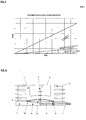
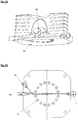
- Fig. 4 the vertical displacement is shown by machine deformation.
- the spring elements (07) and (08) experience an increase in pressure while the pressure drops in the elements (06) and (09).
- the liquid flows from the more heavily loaded upper part to the unloaded spring element (06), which causes a reduction in the resistance of the elastomeric element (08), while at the same time in the elastomeric element (06) resulting liquid reduction is refilled by the liquid from the spring element (08).
- the same principle applies between the spring elements (07) and (09), so that this vertical movement takes place with significantly smaller spring stiffness.
- Fig. 5 shows a diagram with the high stiffness in the torsion direction and the lower stiffness with vertical displacement of the transmission to the machine frame.
- the elastomer components are designed so that they can continue to operate without liquid.
- the valve (32) is opened automatically, so that in the connecting lines (34 and 35) the same pressure again arises, which is the case after a short time.
- the system is then back in its original state, so that the pressure switch (32) can be closed again.
- the valve function described above in addition to the vibration reduction also has the advantage that the hydraulic lines do not have to be designed for the prevailing at extreme load pressure. Furthermore, the extreme loads can be reduced by the damping occurring in the connecting line with the additional throttle (33). While the pressure relief valve (31) are effective with the throttle (33) only in extreme load case, more restrictors (36 and 37) can be arranged in the pressure and discharge side. These bring a damping in the overall system while the system works. That Any displacement of the machine frame is usually associated with vibrations of the entire system. These vibrations are damped by the existing throttles (36 and 37), which causes a load reduction in the wind turbine. The restrictors (36 and 37) may be incorporated in the form of adjustable prior art restrictors. However, it is also possible to dimension all hydraulic lines so that the throttle function is already obtained by the fluid friction in the lines.
- Elastomeric hydraulic storage can also be used in gearless systems.
- the generator is equally direct - without elastic coupling - arranged on the rotor shaft.
- the system thus has the same problem as transmission systems.
- Fig. 22 are arranged as an example 2 pairs.
- inventions can be connected to the generator - as in Fig. 22 described axially arranged.
- Figure 22 shows the arrangement of the bearing behind the generator on the side facing away from the rotor. An arrangement in front of the generator, in the direction of the rotor is also possible.
Claims (18)
- Elément de ressort qui peut être réglé en termes de raideur au moyen d'une pression générée hydrauliquement, convenant pour des pressions de 100 bars à 1500 bars, comprenant :(i) deux couches en élastomère ou plus (1) et une ou plusieurs inter-couche(s) non élastique(s) (2), dans lequel les couches en élastomère sont séparées l'une de l'autre ou les unes des autres par les inter-couches non élastiques, et les inter-couches non élastiques comportent une ouverture ou un trou agencé(e) centralement, de telle sorte que l'élément de ressort comporte, au moins dans son intérieur, une région d'âme élastomérique continue à laquelle les couches en élastomère individuelles sont connectées, et(ii) au moins un dispositif hydraulique (4, 7, 9, 11, 12), lequel est monté au niveau de l'extrémité supérieure et/ou inférieure de l'élément de ressort similaire à une couche et génère une compression du matériau d'élastomère (1) dans la direction verticale par rapport aux couches de l'élément de ressort au moyen de l'introduction d'un fluide hydraulique à l'intérieur de l'élément de ressort au moyen d'une pression hydraulique et conduit ainsi à la formation ou à l'agrandissement d'un espace de déplacement qui contient du fluide hydraulique dans la région d'âme élastomérique de l'élément de ressort, dans lequelcaractérisé en ce que le dispositif hydraulique comprend un ou plusieurs élément(s) d'étanchéité (10, 10a, 6, 21, 22, 24) qui présente(nt) une pré-tension et qui est/sont agencé(s) de telle sorte qu'il(s) génère(nt) une pression augmentée, par comparaison avec la pression dans l'espace de membrane, sur la membrane de pression dans la région de sa/leur connexion ferme/sûre sur le dispositif hydraulique, de telle sorte que l'espace de membrane soit fermé d'une manière étanche à la pression par rapport aux couches de l'élément de ressort d'une part et part rapport au dispositif hydraulique ou à des parties de ce dispositif hydraulique d'autre part.(a) une membrane de pression de forme en correspondance élastique (5), (25) est agencée entre les couches en élastomère (1) de l'élément de ressort et l'espace de déplacement et elle est connectée fermement au niveau de son bord au dispositif hydraulique ou à des parties de celui-ci, de telle sorte qu'un espace de membrane (12) qui contient du fluide hydraulique se forme, lequel espace de membrane correspond à l'espace de déplacement dans le cas d'une pression hydraulique, et (b) le dispositif hydraulique est connecté à l'espace de membrane via une ligne hydraulique (4),
- Elément de ressort selon la revendication 1, caractérisé en ce que la membrane de pression élastique (5) s'étend sur une plaque de membrane (9) qui appartient au dispositif hydraulique, et elle est connectée au niveau de son bord à cette plaque via un talon/bourrelet élastique (10), lequel remplit un évidement en forme de gorge en T (10a) qui est ménagé dans la plaque de membrane, et un élément d'augmentation de pression non élastique (6), lequel présente un profil d'une forme en correspondance qui, dans le cas de la pré-tension, est forcé à l'intérieur du matériau élastique dans la région du talon/bourrelet de la membrane de pression et par conséquent, assure une étanchéité spécifique dans la région de la gorge en T de la plaque de membrane, est agencé entre la couche en élastomère (1) et la membrane de pression dans la région de son talon/ bourrelet.
- Elément de ressort selon l'une des revendications 1 ou 2, caractérisé en ce qu'un espace de pré-tension (10c) est présent entre l'élément d'augmentation de pression (6) et le talon/bourrelet élastique (10) de la membrane de pression.
- Elément de ressort selon la revendication 2, caractérisé en ce que l'élément d'augmentation de pression a été remplacé par la plaque de membrane (9) elle-même, laquelle est comprimée dans la région de la gorge en T, de telle sorte qu'une étanchéité est assurée dans cette région.
- Elément de ressort selon l'une des revendications 1 à 4, caractérisé en ce que la couche en élastomère (1) est incurvée d'une manière concave dans la région de la zone de contact avec la membrane de pression (5), de telle sorte qu'une membrane lenticulaire ou un espace de déplacement est présent(e).
- Elément de ressort selon l'une des revendications 1 à 5, caractérisé en ce que la plaque de membrane (9) comporte des lignes (4) d'alimentation hydraulique et des connexions afférentes (7) qui courent au travers de la plaque de membrane et qui débouchent à l'intérieur de l'espace de membrane.
- Elément de ressort selon l'une des revendications 1 à 6, caractérisé en ce que l'élément de ressort comporte une plaque de support (11) pour les couches en élastomère (1).
- Elément de ressort selon la revendication 7, caractérisé en ce que la plaque de membrane (9) est une partie séparée de la plaque de support (11) et elle est mise sous tension contre cette dernière.
- Elément de ressort selon la revendication 1, caractérisé en ce que la membrane de pression élastique (25) comporte un talon/bourrelet en forme de T élastique terminal circonférentiel (10), lequel est constitué par un talon/bourrelet externe (26) et par un talon/bourrelet interne (23), et elle est connectée d'une manière étanche à la pression à une plaque de membrane (9) qui appartient au dispositif hydraulique de telle sorte que lesdits talons/bourrelets soient introduits à l'intérieur d'un profil creux en forme de T adapté en forme en correspondance, lequel est formé par une tête de membrane de forme en correspondance (9a) et un disque de pré-tension (21), dans lequel (a) la tête de membrane est agencée à l'intérieur de la membrane et de l'espace de membrane (12) et elle comporte une lèvre en saillie circonférentielle, laquelle loge le talon/bourrelet interne (23) de la membrane, et (b) la plaque de pré-tension comporte une ouverture en forme d'anneau/de bague qui loge la tête de membrane (9a) avec la membrane de pression selon un ajustement précis, et le bord de l'ouverture est formé par une lèvre en saillie qui loge le talon/bourrelet élastique externe (26) de la membrane.
- Elément de ressort selon la revendication 9, caractérisé en ce que le disque de pré-tension (21) s'étend en totalité ou partiellement sur la plaque de membrane (9) et est agencé entre cette dernière et la couche en élastomère (1).
- Elément de ressort selon la revendication 9, caractérisé en ce que le disque de pré-tension (21) est la plaque de support pour l'élément de ressort et il comporte, dans la région de la membrane de pression, un évidement d'ajustement de précision à l'intérieur duquel la plaque de membrane de forme en correspondance (9) est insérée.
- Elément de ressort selon l'une des revendications 9 à 11, caractérisé en ce que la plaque de membrane (9) comporte une ligne d'alimentation hydraulique et une connexion afférente (4, 7), dans lequel la ligne d'alimentation hydraulique court au travers de la tête de membrane (9a) et débouche à l'intérieur de l'espace de membrane (12).
- Elément de ressort selon l'une des revendications 9 à 12, caractérisé en ce qu'un espace de pré-tension (22) est ménagé, lequel, dans l'état non sous tension, est formé dans la région dans laquelle le talon/bourrelet externe (26), le disque à membrane (9) et le disque de pré-tension (21) coïncident, et lequel est complétement fermé lorsque les parties (21) et (9) sont mises sous tension en exerçant une force dans le matériau de talon/bourrelet.
- Elément de ressort selon l'une des revendications 9 à 13, caractérisé en ce que la membrane de pression (25) est rigide et elle comporte une surface paraboloïde ou conique, laquelle, avec la tête de membrane (9a) qui est située sur la base, forme une cavité de membrane similaire à un chapeau conique de forme en correspondance (12) ou un chapeau conique de membrane (12a).
- Elément de ressort selon la revendication 14, caractérisé en ce que les couches en élastomère (1) dans l'âme de l'élément de ressort comportent une cavité conique, d'une forme qui correspond à celle de la cavité de membrane (12), laquelle cavité est remplie par le chapeau conique de membrane (12a) qui est formé par la membrane de pression.
- Elément de ressort selon l'une des revendications 1 à 15, caractérisé en ce qu'il comporte, sur un côté, un dispositif hydraulique correspondant et sur le côté opposé, un évidement en forme de cavité (40) dans le matériau d'élastomère, lequel évidement est conformé et configuré de telle sorte qu'il soit séparé de l'espace de membrane (12) au moyen d'un pont (42) en matériau d'élastomère qui est formé par les couches (1), de telle sorte que le pont puisse être forcé à l'intérieur de l'évidement en forme de cavité lorsque la pression hydraulique dans l'espace de membrane est augmentée.
- Palier de machine ou de boîte de vitesses/transmission, comprenant au moins deux éléments de ressort selon les revendications 1 à 16 qui sont alignés dans la même direction.
- Utilisation d'un palier selon la revendication 17 pour absorber des forces de flexion, de déformation et de déplacement dans des éoliennes pour des installations sur lesquelles une boîte de vitesses/transmission est montée et pour des installations sans engrenages/à entraînement direct.
Priority Applications (2)
| Application Number | Priority Date | Filing Date | Title |
|---|---|---|---|
| EP08010491.2A EP2003362B1 (fr) | 2007-06-14 | 2008-06-10 | Elément de ressort en élastomère précontaint de manière hydraulique et son utilisation dans des supports d'éoliennes |
| PL08010491T PL2003362T3 (pl) | 2007-06-14 | 2008-06-10 | Hydraulicznie wstępnie naprężony element sprężysty oraz jego zastosowanie w podporach elektrowni wiatrowych |
Applications Claiming Priority (2)
| Application Number | Priority Date | Filing Date | Title |
|---|---|---|---|
| EP07011643 | 2007-06-14 | ||
| EP08010491.2A EP2003362B1 (fr) | 2007-06-14 | 2008-06-10 | Elément de ressort en élastomère précontaint de manière hydraulique et son utilisation dans des supports d'éoliennes |
Publications (3)
| Publication Number | Publication Date |
|---|---|
| EP2003362A2 EP2003362A2 (fr) | 2008-12-17 |
| EP2003362A3 EP2003362A3 (fr) | 2014-11-19 |
| EP2003362B1 true EP2003362B1 (fr) | 2017-11-01 |
Family
ID=39776594
Family Applications (1)
| Application Number | Title | Priority Date | Filing Date |
|---|---|---|---|
| EP08010491.2A Active EP2003362B1 (fr) | 2007-06-14 | 2008-06-10 | Elément de ressort en élastomère précontaint de manière hydraulique et son utilisation dans des supports d'éoliennes |
Country Status (7)
| Country | Link |
|---|---|
| US (1) | US8210507B2 (fr) |
| EP (1) | EP2003362B1 (fr) |
| CN (1) | CN101429929B (fr) |
| DK (1) | DK2003362T3 (fr) |
| ES (1) | ES2656409T3 (fr) |
| PL (1) | PL2003362T3 (fr) |
| PT (1) | PT2003362T (fr) |
Cited By (2)
| Publication number | Priority date | Publication date | Assignee | Title |
|---|---|---|---|---|
| EP3892876A1 (fr) | 2020-04-08 | 2021-10-13 | FM Energie GmbH & Co. KG | Accouplement élastique à cames à moments de flexion réduits |
| DE102021206314A1 (de) | 2021-06-21 | 2022-12-22 | Zf Friedrichshafen Ag | Anordnung für eine Getriebelagerung |
Families Citing this family (41)
| Publication number | Priority date | Publication date | Assignee | Title |
|---|---|---|---|---|
| US8302988B2 (en) | 2008-03-10 | 2012-11-06 | Hendrickson Usa, L.L.C. | Suspension assembly with tie-plate |
| EP2143944B1 (fr) * | 2008-07-07 | 2018-10-17 | Siemens Aktiengesellschaft | Éolienne |
| DE102009010584B4 (de) * | 2009-02-20 | 2011-06-16 | Nordex Energy Gmbh | Vorrichtung zur Positionierung eines Getriebes in einer Windenergieanlage |
| ES2378199B1 (es) * | 2009-06-24 | 2013-06-05 | Acciona Windpower S.A. | Sistema de unión de una góndola con la torre de hormigón de un aerogenerador. |
| CN102792015A (zh) * | 2010-01-19 | 2012-11-21 | 弗朗兹·米特希 | 带有可机械地调整的刚度的弹性体弹簧 |
| ES2536686T3 (es) | 2010-02-08 | 2015-05-27 | Vestas Wind Systems A/S | Elemento elástico, conjunto de suspensión y turbina eólica con el conjunto de suspensión |
| DE102010009863A1 (de) | 2010-03-02 | 2011-09-08 | Robert Bosch Gmbh | Einrichtung und Verfahren zur Reduzierung von Lasten |
| US20110140441A1 (en) * | 2010-08-11 | 2011-06-16 | General Electric Company | Gearbox support system |
| US20110140440A1 (en) * | 2010-08-11 | 2011-06-16 | General Electric Company | Gearbox support system |
| EP2434154A1 (fr) * | 2010-09-28 | 2012-03-28 | Siemens Aktiengesellschaft | Agencement d'amortissement actif d'éolienne |
| WO2013042252A1 (fr) | 2011-09-22 | 2013-03-28 | 三菱重工業株式会社 | Dispositif générateur d'énergie à récupération d'énergie, et procédé de verrouillage de rotor pour ce dispositif |
| KR20130053416A (ko) * | 2010-11-30 | 2013-05-23 | 미츠비시 쥬고교 가부시키가이샤 | 재생 에너지형 발전 장치 |
| JP5502190B2 (ja) * | 2010-11-30 | 2014-05-28 | 三菱重工業株式会社 | 再生エネルギー型発電装置 |
| JP5501982B2 (ja) | 2010-11-30 | 2014-05-28 | 三菱重工業株式会社 | 風力発電装置または潮流発電装置の油圧ポンプ構造および油圧ポンプの組み付け方法 |
| US9284975B2 (en) * | 2011-03-09 | 2016-03-15 | FM Energie GmbH & Co., KG | Bushing which can be pretensioned by material displacement and bearing equipped with said bushing |
| JP4950368B1 (ja) | 2011-04-05 | 2012-06-13 | 三菱重工業株式会社 | 再生エネルギー型発電装置 |
| US9004512B2 (en) | 2011-07-08 | 2015-04-14 | Hendrickson Usa, L.L.C. | Shear spring useful for vehicle suspension |
| AU2012282874B2 (en) | 2011-07-08 | 2014-09-25 | Hendrickson Usa, L.L.C. | Vehicle suspension and improved method of assembly |
| PT2732157T (pt) | 2011-07-14 | 2019-06-04 | Esm Energie Und Schwingungstechnik Mitsch Gmbh | Depósito de acumulação de pressão elástica, hidráulica ou pneumática e sua aplicação em instalações de energia eólica |
| CN103124844A (zh) * | 2011-09-22 | 2013-05-29 | 三菱重工业株式会社 | 再生能源型发电装置及其旋转叶片装卸方法 |
| JP5808696B2 (ja) * | 2012-03-01 | 2015-11-10 | 住友重機械工業株式会社 | 風力発電装置 |
| JP5705139B2 (ja) * | 2012-01-16 | 2015-04-22 | 住友重機械工業株式会社 | 風力発電装置 |
| JP5705152B2 (ja) * | 2012-02-29 | 2015-04-22 | 住友重機械工業株式会社 | 風力発電装置 |
| USD700113S1 (en) | 2012-07-06 | 2014-02-25 | Hendrickson Usa, L.L.C. | Suspension assembly |
| USD699637S1 (en) | 2012-07-06 | 2014-02-18 | Hendrickson Usa, L.L.C. | Shear spring for a suspension |
| WO2014040715A1 (fr) * | 2012-09-13 | 2014-03-20 | Esm Energie- Und Schwingungstechnik Mitsch Gmbh | Palier oscillant élastique |
| CN103075460A (zh) * | 2012-10-23 | 2013-05-01 | 镇江铁科橡塑制品有限公司 | 具有自保护功能的液压辅助弹性支撑总成 |
| US9085212B2 (en) | 2013-03-15 | 2015-07-21 | Hendrickson Usa, L.L.C. | Vehicle suspension |
| US9150071B2 (en) | 2013-07-25 | 2015-10-06 | Hendrickson Usa, L.L.C. | Frame hanger for vehicle suspension |
| US9856966B2 (en) | 2014-08-27 | 2018-01-02 | General Electric Company | Drivetrain assembly for a wind turbine |
| DK178642B9 (en) * | 2015-03-16 | 2016-10-24 | Envision Energy Denmark Aps | Wind turbine comprising a torque dampening unit |
| DE102015224744A1 (de) * | 2015-12-09 | 2017-06-14 | Contitech Luftfedersysteme Gmbh | Gummi-Metall-Federelement |
| CN105422715B (zh) * | 2015-12-31 | 2018-02-02 | 江苏铁科新材料股份有限公司 | 液压辅助弹性支撑装置 |
| US10415544B2 (en) | 2017-01-03 | 2019-09-17 | General Electric Company | System and method for determining torque on a wind turbine shaft |
| US10619721B2 (en) | 2017-07-21 | 2020-04-14 | General Electric Company | Drivetrain assembly for a wind turbine |
| CN107906200A (zh) * | 2017-10-17 | 2018-04-13 | 株洲时代新材料科技股份有限公司 | 用于液体复合弹簧的密封件和液体复合弹簧 |
| CN107654648B (zh) * | 2017-10-17 | 2024-02-27 | 株洲时代新材料科技股份有限公司 | 用于液体复合弹簧的密封件和液体复合弹簧 |
| US10816094B2 (en) * | 2017-10-17 | 2020-10-27 | Zhuzhou Times New Material Technology Co. Ltd. | Sealing member for liquid composite spring and liquid composite spring |
| CN107701702A (zh) * | 2017-10-17 | 2018-02-16 | 株洲时代新材料科技股份有限公司 | 一种用于齿轮箱的液压支撑装置 |
| DE102021210007A1 (de) | 2021-09-10 | 2023-03-16 | Zf Friedrichshafen Ag | Federnd gelagertes Getriebegehäuse |
| DE102022204900B3 (de) * | 2022-05-17 | 2023-09-07 | Zf Friedrichshafen Ag | Federnd gelagertes Getriebegehäuse II |
Family Cites Families (7)
| Publication number | Priority date | Publication date | Assignee | Title |
|---|---|---|---|---|
| GB1429308A (en) * | 1972-04-17 | 1976-03-24 | Dunlop Ltd | Railway vehicles |
| JPH0781605B2 (ja) * | 1989-02-01 | 1995-09-06 | 東海ゴム工業株式会社 | 電気粘性流体使用装置 |
| FR2806453B1 (fr) * | 2000-03-20 | 2002-05-03 | Hutchinson | Amortisseur de vibrations notamment pour rotor d'helicoptere |
| DE10064769A1 (de) * | 2000-12-22 | 2002-08-29 | Contitech Luftfedersyst Gmbh | Hydrofeder |
| CN2547546Y (zh) * | 2002-06-09 | 2003-04-30 | 株洲时代新材料科技股份有限公司 | 无磨耗非线性阻尼复合减振定位弹簧 |
| DE10307680A1 (de) * | 2003-02-21 | 2004-09-30 | Carl Freudenberg Kg | Hydrolager |
| DK1566543T3 (da) | 2004-02-18 | 2009-12-21 | Franz Mitsch | Elastomerleje med regulerbar stivhed |
-
2008
- 2008-06-10 DK DK08010491.2T patent/DK2003362T3/en active
- 2008-06-10 PL PL08010491T patent/PL2003362T3/pl unknown
- 2008-06-10 ES ES08010491.2T patent/ES2656409T3/es active Active
- 2008-06-10 PT PT80104912T patent/PT2003362T/pt unknown
- 2008-06-10 EP EP08010491.2A patent/EP2003362B1/fr active Active
- 2008-06-13 CN CN2008101254423A patent/CN101429929B/zh active Active
- 2008-06-13 US US12/138,671 patent/US8210507B2/en active Active
Non-Patent Citations (1)
| Title |
|---|
| None * |
Cited By (3)
| Publication number | Priority date | Publication date | Assignee | Title |
|---|---|---|---|---|
| EP3892876A1 (fr) | 2020-04-08 | 2021-10-13 | FM Energie GmbH & Co. KG | Accouplement élastique à cames à moments de flexion réduits |
| DE102021206314A1 (de) | 2021-06-21 | 2022-12-22 | Zf Friedrichshafen Ag | Anordnung für eine Getriebelagerung |
| WO2022268409A1 (fr) | 2021-06-21 | 2022-12-29 | Zf Friedrichshafen Ag | Agencement pour palier de boîte de vitesses |
Also Published As
| Publication number | Publication date |
|---|---|
| CN101429929A (zh) | 2009-05-13 |
| CN101429929B (zh) | 2013-03-27 |
| EP2003362A3 (fr) | 2014-11-19 |
| US8210507B2 (en) | 2012-07-03 |
| US20080308980A1 (en) | 2008-12-18 |
| EP2003362A2 (fr) | 2008-12-17 |
| PT2003362T (pt) | 2018-02-06 |
| ES2656409T3 (es) | 2018-02-27 |
| PL2003362T3 (pl) | 2018-04-30 |
| DK2003362T3 (en) | 2018-01-15 |
Similar Documents
| Publication | Publication Date | Title |
|---|---|---|
| EP2003362B1 (fr) | Elément de ressort en élastomère précontaint de manière hydraulique et son utilisation dans des supports d'éoliennes | |
| EP1566543B1 (fr) | Palier élastomère à rigidité réglable | |
| EP2895768B1 (fr) | Palier oscillant élastique | |
| DE10327408B4 (de) | Vorrichtung zum Dämpfen von Druckpulsationen in einem Kraftstoffsystem einer Brennkraftmaschine | |
| EP2352930B1 (fr) | Palier asymétrique | |
| EP2516883B1 (fr) | Douille de serrage excentrique | |
| EP2526295B1 (fr) | Ressort élastomère avec rigidité réglable de façon mécanique | |
| EP1411236A2 (fr) | Dispositif pour l'atténuation des pulsations de pression dans un système de fluide, en particulier dans un système de carburant d'un moteur à combustion interne | |
| EP1564406B1 (fr) | Palier amortissant pour rotor d'éolienne | |
| EP2732157B1 (fr) | Palier élastique, hydraulique ou pneumatique à accumulateur de pression et utilisation dudit palier dans des éoliennes | |
| EP2683961A1 (fr) | Coussinet pouvant être précontraint par refoulement de matériau et palier équipé de ce coussinet | |
| EP1593867B1 (fr) | Accouplement avec des éléments de portage prestressés | |
| DE2206771A1 (de) | Hochdruckdichtung mit dem o-ring angepasster abstuetzflaeche und kantenbelastetem dichtring | |
| EP2745028B1 (fr) | Absorbeur de vibrations indépendant de la température | |
| EP3012479A1 (fr) | Support a arete elastique pour eoliennes | |
| EP3140552B1 (fr) | Vérin hydraulique plat, coussin de levage, son utilisation, et procédé d'alignement d'un générateur | |
| EP2821665B1 (fr) | Dépôt combiné d'amortissement d'oscillations axiales et radiales | |
| EP1637761B1 (fr) | Frein à disque hydraulique avec actionneur élastique | |
| EP4003764B1 (fr) | Dispositif et procédé d'ajustement d'un point de base d'un élément de ressort pour un véhicule | |
| WO2007000128A1 (fr) | Accumulateur de pression hydraulique | |
| DE102007036608A1 (de) | Zahnradpumpe mit variablem Durchflussvolumen | |
| EP2221475B1 (fr) | Dispositif de positionnement d'une transmission dans une éolienne | |
| DE102021113993A1 (de) | Hydraulische Spannvorrichtung | |
| DE102008050330B3 (de) | Aktive Schwingungsdämpfungsvorrichtung | |
| DE102013221623A1 (de) | Axialkolbenmaschine |
Legal Events
| Date | Code | Title | Description |
|---|---|---|---|
| PUAI | Public reference made under article 153(3) epc to a published international application that has entered the european phase |
Free format text: ORIGINAL CODE: 0009012 |
|
| AK | Designated contracting states |
Kind code of ref document: A2 Designated state(s): AT BE BG CH CY CZ DE DK EE ES FI FR GB GR HR HU IE IS IT LI LT LU LV MC MT NL NO PL PT RO SE SI SK TR |
|
| AX | Request for extension of the european patent |
Extension state: AL BA MK RS |
|
| PUAL | Search report despatched |
Free format text: ORIGINAL CODE: 0009013 |
|
| AK | Designated contracting states |
Kind code of ref document: A3 Designated state(s): AT BE BG CH CY CZ DE DK EE ES FI FR GB GR HR HU IE IS IT LI LT LU LV MC MT NL NO PL PT RO SE SI SK TR |
|
| AX | Request for extension of the european patent |
Extension state: AL BA MK RS |
|
| RIC1 | Information provided on ipc code assigned before grant |
Ipc: F16F 1/40 20060101AFI20141010BHEP Ipc: F16F 13/08 20060101ALI20141010BHEP |
|
| 17P | Request for examination filed |
Effective date: 20150508 |
|
| RBV | Designated contracting states (corrected) |
Designated state(s): AT BE BG CH CY CZ DE DK EE ES FI FR GB GR HR HU IE IS IT LI LT LU LV MC MT NL NO PL PT RO SE SI SK TR |
|
| AKX | Designation fees paid |
Designated state(s): AT BE BG CH CY LI |
|
| AXX | Extension fees paid |
Extension state: MK Extension state: AL Extension state: BA Extension state: RS |
|
| REG | Reference to a national code |
Ref country code: DE Ref legal event code: R108 |
|
| RBV | Designated contracting states (corrected) |
Designated state(s): AT BE BG CH CY CZ DE DK EE ES FI FR GB GR HR HU IE IS IT LI LT LU LV MC MT NL NO PL PT RO SE SI SK TR |
|
| GRAP | Despatch of communication of intention to grant a patent |
Free format text: ORIGINAL CODE: EPIDOSNIGR1 |
|
| INTG | Intention to grant announced |
Effective date: 20170530 |
|
| RAP1 | Party data changed (applicant data changed or rights of an application transferred) |
Owner name: FM ENERGIE GMBH & CO. KG |
|
| RIN1 | Information on inventor provided before grant (corrected) |
Inventor name: FM ENERGIE GMBH & CO. KG |
|
| GRAS | Grant fee paid |
Free format text: ORIGINAL CODE: EPIDOSNIGR3 |
|
| GRAA | (expected) grant |
Free format text: ORIGINAL CODE: 0009210 |
|
| AK | Designated contracting states |
Kind code of ref document: B1 Designated state(s): AT BE BG CH CY CZ DE DK EE ES FI FR GB GR HR HU IE IS IT LI LT LU LV MC MT NL NO PL PT RO SE SI SK TR |
|
| REG | Reference to a national code |
Ref country code: GB Ref legal event code: FG4D Free format text: NOT ENGLISH |
|
| RIN1 | Information on inventor provided before grant (corrected) |
Inventor name: MITSCH, FRANZ |
|
| REG | Reference to a national code |
Ref country code: CH Ref legal event code: EP Ref country code: AT Ref legal event code: REF Ref document number: 942353 Country of ref document: AT Kind code of ref document: T Effective date: 20171115 |
|
| REG | Reference to a national code |
Ref country code: IE Ref legal event code: FG4D Free format text: LANGUAGE OF EP DOCUMENT: GERMAN |
|
| REG | Reference to a national code |
Ref country code: DE Ref legal event code: R096 Ref document number: 502008015699 Country of ref document: DE |
|
| REG | Reference to a national code |
Ref country code: DK Ref legal event code: T3 Effective date: 20180109 |
|
| REG | Reference to a national code |
Ref country code: CH Ref legal event code: NV Representative=s name: BOVARD AG PATENT- UND MARKENANWAELTE, CH |
|
| REG | Reference to a national code |
Ref country code: PT Ref legal event code: SC4A Ref document number: 2003362 Country of ref document: PT Date of ref document: 20180206 Kind code of ref document: T Free format text: AVAILABILITY OF NATIONAL TRANSLATION Effective date: 20180130 |
|
| REG | Reference to a national code |
Ref country code: SE Ref legal event code: TRGR |
|
| REG | Reference to a national code |
Ref country code: ES Ref legal event code: FG2A Ref document number: 2656409 Country of ref document: ES Kind code of ref document: T3 Effective date: 20180227 |
|
| REG | Reference to a national code |
Ref country code: NL Ref legal event code: MP Effective date: 20171101 |
|
| REG | Reference to a national code |
Ref country code: LT Ref legal event code: MG4D |
|
| PG25 | Lapsed in a contracting state [announced via postgrant information from national office to epo] |
Ref country code: NL Free format text: LAPSE BECAUSE OF FAILURE TO SUBMIT A TRANSLATION OF THE DESCRIPTION OR TO PAY THE FEE WITHIN THE PRESCRIBED TIME-LIMIT Effective date: 20171101 Ref country code: NO Free format text: LAPSE BECAUSE OF FAILURE TO SUBMIT A TRANSLATION OF THE DESCRIPTION OR TO PAY THE FEE WITHIN THE PRESCRIBED TIME-LIMIT Effective date: 20180201 Ref country code: LT Free format text: LAPSE BECAUSE OF FAILURE TO SUBMIT A TRANSLATION OF THE DESCRIPTION OR TO PAY THE FEE WITHIN THE PRESCRIBED TIME-LIMIT Effective date: 20171101 Ref country code: FI Free format text: LAPSE BECAUSE OF FAILURE TO SUBMIT A TRANSLATION OF THE DESCRIPTION OR TO PAY THE FEE WITHIN THE PRESCRIBED TIME-LIMIT Effective date: 20171101 |
|
| PG25 | Lapsed in a contracting state [announced via postgrant information from national office to epo] |
Ref country code: HR Free format text: LAPSE BECAUSE OF FAILURE TO SUBMIT A TRANSLATION OF THE DESCRIPTION OR TO PAY THE FEE WITHIN THE PRESCRIBED TIME-LIMIT Effective date: 20171101 Ref country code: GR Free format text: LAPSE BECAUSE OF FAILURE TO SUBMIT A TRANSLATION OF THE DESCRIPTION OR TO PAY THE FEE WITHIN THE PRESCRIBED TIME-LIMIT Effective date: 20180202 Ref country code: BG Free format text: LAPSE BECAUSE OF FAILURE TO SUBMIT A TRANSLATION OF THE DESCRIPTION OR TO PAY THE FEE WITHIN THE PRESCRIBED TIME-LIMIT Effective date: 20180201 Ref country code: LV Free format text: LAPSE BECAUSE OF FAILURE TO SUBMIT A TRANSLATION OF THE DESCRIPTION OR TO PAY THE FEE WITHIN THE PRESCRIBED TIME-LIMIT Effective date: 20171101 Ref country code: IS Free format text: LAPSE BECAUSE OF FAILURE TO SUBMIT A TRANSLATION OF THE DESCRIPTION OR TO PAY THE FEE WITHIN THE PRESCRIBED TIME-LIMIT Effective date: 20180301 |
|
| REG | Reference to a national code |
Ref country code: FR Ref legal event code: PLFP Year of fee payment: 11 |
|
| PG25 | Lapsed in a contracting state [announced via postgrant information from national office to epo] |
Ref country code: SK Free format text: LAPSE BECAUSE OF FAILURE TO SUBMIT A TRANSLATION OF THE DESCRIPTION OR TO PAY THE FEE WITHIN THE PRESCRIBED TIME-LIMIT Effective date: 20171101 Ref country code: EE Free format text: LAPSE BECAUSE OF FAILURE TO SUBMIT A TRANSLATION OF THE DESCRIPTION OR TO PAY THE FEE WITHIN THE PRESCRIBED TIME-LIMIT Effective date: 20171101 Ref country code: CY Free format text: LAPSE BECAUSE OF FAILURE TO SUBMIT A TRANSLATION OF THE DESCRIPTION OR TO PAY THE FEE WITHIN THE PRESCRIBED TIME-LIMIT Effective date: 20171101 Ref country code: CZ Free format text: LAPSE BECAUSE OF FAILURE TO SUBMIT A TRANSLATION OF THE DESCRIPTION OR TO PAY THE FEE WITHIN THE PRESCRIBED TIME-LIMIT Effective date: 20171101 |
|
| REG | Reference to a national code |
Ref country code: DE Ref legal event code: R097 Ref document number: 502008015699 Country of ref document: DE |
|
| PG25 | Lapsed in a contracting state [announced via postgrant information from national office to epo] |
Ref country code: IT Free format text: LAPSE BECAUSE OF FAILURE TO SUBMIT A TRANSLATION OF THE DESCRIPTION OR TO PAY THE FEE WITHIN THE PRESCRIBED TIME-LIMIT Effective date: 20171101 Ref country code: RO Free format text: LAPSE BECAUSE OF FAILURE TO SUBMIT A TRANSLATION OF THE DESCRIPTION OR TO PAY THE FEE WITHIN THE PRESCRIBED TIME-LIMIT Effective date: 20171101 |
|
| PLBE | No opposition filed within time limit |
Free format text: ORIGINAL CODE: 0009261 |
|
| STAA | Information on the status of an ep patent application or granted ep patent |
Free format text: STATUS: NO OPPOSITION FILED WITHIN TIME LIMIT |
|
| PG25 | Lapsed in a contracting state [announced via postgrant information from national office to epo] |
Ref country code: MT Free format text: LAPSE BECAUSE OF FAILURE TO SUBMIT A TRANSLATION OF THE DESCRIPTION OR TO PAY THE FEE WITHIN THE PRESCRIBED TIME-LIMIT Effective date: 20171101 |
|
| 26N | No opposition filed |
Effective date: 20180802 |
|
| PG25 | Lapsed in a contracting state [announced via postgrant information from national office to epo] |
Ref country code: SI Free format text: LAPSE BECAUSE OF FAILURE TO SUBMIT A TRANSLATION OF THE DESCRIPTION OR TO PAY THE FEE WITHIN THE PRESCRIBED TIME-LIMIT Effective date: 20171101 |
|
| REG | Reference to a national code |
Ref country code: BE Ref legal event code: MM Effective date: 20180630 |
|
| REG | Reference to a national code |
Ref country code: IE Ref legal event code: MM4A |
|
| PG25 | Lapsed in a contracting state [announced via postgrant information from national office to epo] |
Ref country code: LU Free format text: LAPSE BECAUSE OF NON-PAYMENT OF DUE FEES Effective date: 20180610 Ref country code: MC Free format text: LAPSE BECAUSE OF FAILURE TO SUBMIT A TRANSLATION OF THE DESCRIPTION OR TO PAY THE FEE WITHIN THE PRESCRIBED TIME-LIMIT Effective date: 20171101 |
|
| PG25 | Lapsed in a contracting state [announced via postgrant information from national office to epo] |
Ref country code: IE Free format text: LAPSE BECAUSE OF NON-PAYMENT OF DUE FEES Effective date: 20180610 |
|
| PG25 | Lapsed in a contracting state [announced via postgrant information from national office to epo] |
Ref country code: BE Free format text: LAPSE BECAUSE OF NON-PAYMENT OF DUE FEES Effective date: 20180630 |
|
| REG | Reference to a national code |
Ref country code: AT Ref legal event code: MM01 Ref document number: 942353 Country of ref document: AT Kind code of ref document: T Effective date: 20180610 |
|
| PG25 | Lapsed in a contracting state [announced via postgrant information from national office to epo] |
Ref country code: AT Free format text: LAPSE BECAUSE OF NON-PAYMENT OF DUE FEES Effective date: 20180610 |
|
| PG25 | Lapsed in a contracting state [announced via postgrant information from national office to epo] |
Ref country code: HU Free format text: LAPSE BECAUSE OF FAILURE TO SUBMIT A TRANSLATION OF THE DESCRIPTION OR TO PAY THE FEE WITHIN THE PRESCRIBED TIME-LIMIT; INVALID AB INITIO Effective date: 20080610 |
|
| PGFP | Annual fee paid to national office [announced via postgrant information from national office to epo] |
Ref country code: SE Payment date: 20200616 Year of fee payment: 13 |
|
| PG25 | Lapsed in a contracting state [announced via postgrant information from national office to epo] |
Ref country code: PT Free format text: LAPSE BECAUSE OF NON-PAYMENT OF DUE FEES Effective date: 20201210 |
|
| PG25 | Lapsed in a contracting state [announced via postgrant information from national office to epo] |
Ref country code: PT Free format text: LAPSE BECAUSE OF NON-PAYMENT OF DUE FEES Effective date: 20210114 |
|
| PGFP | Annual fee paid to national office [announced via postgrant information from national office to epo] |
Ref country code: PL Payment date: 20210526 Year of fee payment: 14 Ref country code: TR Payment date: 20210531 Year of fee payment: 14 |
|
| REG | Reference to a national code |
Ref country code: SE Ref legal event code: EUG |
|
| PG25 | Lapsed in a contracting state [announced via postgrant information from national office to epo] |
Ref country code: SE Free format text: LAPSE BECAUSE OF NON-PAYMENT OF DUE FEES Effective date: 20210611 |
|
| PGFP | Annual fee paid to national office [announced via postgrant information from national office to epo] |
Ref country code: FR Payment date: 20230614 Year of fee payment: 16 Ref country code: DK Payment date: 20230622 Year of fee payment: 16 |
|
| PGFP | Annual fee paid to national office [announced via postgrant information from national office to epo] |
Ref country code: GB Payment date: 20230504 Year of fee payment: 16 Ref country code: ES Payment date: 20230703 Year of fee payment: 16 Ref country code: CH Payment date: 20230702 Year of fee payment: 16 |
|
| PG25 | Lapsed in a contracting state [announced via postgrant information from national office to epo] |
Ref country code: PL Free format text: LAPSE BECAUSE OF NON-PAYMENT OF DUE FEES Effective date: 20220610 |
|
| PGFP | Annual fee paid to national office [announced via postgrant information from national office to epo] |
Ref country code: DE Payment date: 20230818 Year of fee payment: 16 |