EP2003362B1 - Hydraulically pre-tensioned elastomeric spring element and its use in bearings for wind power facilities - Google Patents
Hydraulically pre-tensioned elastomeric spring element and its use in bearings for wind power facilities Download PDFInfo
- Publication number
- EP2003362B1 EP2003362B1 EP08010491.2A EP08010491A EP2003362B1 EP 2003362 B1 EP2003362 B1 EP 2003362B1 EP 08010491 A EP08010491 A EP 08010491A EP 2003362 B1 EP2003362 B1 EP 2003362B1
- Authority
- EP
- European Patent Office
- Prior art keywords
- membrane
- spring element
- pressure
- space
- hydraulic
- Prior art date
- Legal status (The legal status is an assumption and is not a legal conclusion. Google has not performed a legal analysis and makes no representation as to the accuracy of the status listed.)
- Active
Links
- 239000012528 membrane Substances 0.000 claims description 235
- 229920001971 elastomer Polymers 0.000 claims description 80
- 239000000806 elastomer Substances 0.000 claims description 79
- 239000011324 bead Substances 0.000 claims description 50
- 238000006073 displacement reaction Methods 0.000 claims description 36
- 239000012530 fluid Substances 0.000 claims description 29
- 239000000463 material Substances 0.000 claims description 23
- 238000007789 sealing Methods 0.000 claims description 12
- 230000006835 compression Effects 0.000 claims description 5
- 238000007906 compression Methods 0.000 claims description 5
- 238000009434 installation Methods 0.000 claims description 5
- 239000013013 elastic material Substances 0.000 claims description 3
- 230000015572 biosynthetic process Effects 0.000 claims description 2
- 239000010410 layer Substances 0.000 claims 12
- 239000011229 interlayer Substances 0.000 claims 3
- 210000004379 membrane Anatomy 0.000 description 192
- 230000005540 biological transmission Effects 0.000 description 13
- 230000036316 preload Effects 0.000 description 11
- 238000003860 storage Methods 0.000 description 11
- 238000013016 damping Methods 0.000 description 10
- 239000007788 liquid Substances 0.000 description 9
- 239000013536 elastomeric material Substances 0.000 description 6
- 238000005452 bending Methods 0.000 description 5
- 230000009467 reduction Effects 0.000 description 5
- 244000043261 Hevea brasiliensis Species 0.000 description 4
- 238000010276 construction Methods 0.000 description 4
- 239000002184 metal Substances 0.000 description 4
- 229920003052 natural elastomer Polymers 0.000 description 4
- 229920001194 natural rubber Polymers 0.000 description 4
- 238000004073 vulcanization Methods 0.000 description 4
- 230000008901 benefit Effects 0.000 description 3
- 235000015095 lager Nutrition 0.000 description 3
- 239000004033 plastic Substances 0.000 description 3
- 229920003023 plastic Polymers 0.000 description 3
- 239000011148 porous material Substances 0.000 description 3
- 241000196324 Embryophyta Species 0.000 description 2
- 150000001298 alcohols Chemical class 0.000 description 2
- 239000011230 binding agent Substances 0.000 description 2
- 230000008878 coupling Effects 0.000 description 2
- 238000010168 coupling process Methods 0.000 description 2
- 238000005859 coupling reaction Methods 0.000 description 2
- 230000000694 effects Effects 0.000 description 2
- 239000000203 mixture Substances 0.000 description 2
- XLYOFNOQVPJJNP-UHFFFAOYSA-N water Substances O XLYOFNOQVPJJNP-UHFFFAOYSA-N 0.000 description 2
- 229920000049 Carbon (fiber) Polymers 0.000 description 1
- 241001295925 Gegenes Species 0.000 description 1
- 238000005299 abrasion Methods 0.000 description 1
- 239000000654 additive Substances 0.000 description 1
- 239000000853 adhesive Substances 0.000 description 1
- 230000001070 adhesive effect Effects 0.000 description 1
- 230000002528 anti-freeze Effects 0.000 description 1
- TZCXTZWJZNENPQ-UHFFFAOYSA-L barium sulfate Chemical compound [Ba+2].[O-]S([O-])(=O)=O TZCXTZWJZNENPQ-UHFFFAOYSA-L 0.000 description 1
- 230000033228 biological regulation Effects 0.000 description 1
- 230000009172 bursting Effects 0.000 description 1
- 239000004917 carbon fiber Substances 0.000 description 1
- 230000008859 change Effects 0.000 description 1
- 238000004891 communication Methods 0.000 description 1
- 239000002131 composite material Substances 0.000 description 1
- 230000007423 decrease Effects 0.000 description 1
- 238000010586 diagram Methods 0.000 description 1
- 239000000428 dust Substances 0.000 description 1
- 238000005516 engineering process Methods 0.000 description 1
- 238000007667 floating Methods 0.000 description 1
- 239000010720 hydraulic oil Substances 0.000 description 1
- 238000002955 isolation Methods 0.000 description 1
- 238000004519 manufacturing process Methods 0.000 description 1
- 230000005226 mechanical processes and functions Effects 0.000 description 1
- VNWKTOKETHGBQD-UHFFFAOYSA-N methane Chemical compound C VNWKTOKETHGBQD-UHFFFAOYSA-N 0.000 description 1
- 230000005012 migration Effects 0.000 description 1
- 238000013508 migration Methods 0.000 description 1
- 239000003921 oil Substances 0.000 description 1
- 230000000149 penetrating effect Effects 0.000 description 1
- 230000035515 penetration Effects 0.000 description 1
- 238000002360 preparation method Methods 0.000 description 1
- 238000003825 pressing Methods 0.000 description 1
- 238000005096 rolling process Methods 0.000 description 1
- 239000007787 solid Substances 0.000 description 1
- 210000002023 somite Anatomy 0.000 description 1
Images


Classifications
-
- F—MECHANICAL ENGINEERING; LIGHTING; HEATING; WEAPONS; BLASTING
- F16—ENGINEERING ELEMENTS AND UNITS; GENERAL MEASURES FOR PRODUCING AND MAINTAINING EFFECTIVE FUNCTIONING OF MACHINES OR INSTALLATIONS; THERMAL INSULATION IN GENERAL
- F16F—SPRINGS; SHOCK-ABSORBERS; MEANS FOR DAMPING VIBRATION
- F16F1/00—Springs
- F16F1/36—Springs made of rubber or other material having high internal friction, e.g. thermoplastic elastomers
- F16F1/40—Springs made of rubber or other material having high internal friction, e.g. thermoplastic elastomers consisting of a stack of similar elements separated by non-elastic intermediate layers
-
- F—MECHANICAL ENGINEERING; LIGHTING; HEATING; WEAPONS; BLASTING
- F03—MACHINES OR ENGINES FOR LIQUIDS; WIND, SPRING, OR WEIGHT MOTORS; PRODUCING MECHANICAL POWER OR A REACTIVE PROPULSIVE THRUST, NOT OTHERWISE PROVIDED FOR
- F03D—WIND MOTORS
- F03D80/00—Details, components or accessories not provided for in groups F03D1/00 - F03D17/00
- F03D80/70—Bearing or lubricating arrangements
-
- F—MECHANICAL ENGINEERING; LIGHTING; HEATING; WEAPONS; BLASTING
- F16—ENGINEERING ELEMENTS AND UNITS; GENERAL MEASURES FOR PRODUCING AND MAINTAINING EFFECTIVE FUNCTIONING OF MACHINES OR INSTALLATIONS; THERMAL INSULATION IN GENERAL
- F16F—SPRINGS; SHOCK-ABSORBERS; MEANS FOR DAMPING VIBRATION
- F16F13/00—Units comprising springs of the non-fluid type as well as vibration-dampers, shock-absorbers, or fluid springs
- F16F13/04—Units comprising springs of the non-fluid type as well as vibration-dampers, shock-absorbers, or fluid springs comprising both a plastics spring and a damper, e.g. a friction damper
- F16F13/06—Units comprising springs of the non-fluid type as well as vibration-dampers, shock-absorbers, or fluid springs comprising both a plastics spring and a damper, e.g. a friction damper the damper being a fluid damper, e.g. the plastics spring not forming a part of the wall of the fluid chamber of the damper
- F16F13/08—Units comprising springs of the non-fluid type as well as vibration-dampers, shock-absorbers, or fluid springs comprising both a plastics spring and a damper, e.g. a friction damper the damper being a fluid damper, e.g. the plastics spring not forming a part of the wall of the fluid chamber of the damper the plastics spring forming at least a part of the wall of the fluid chamber of the damper
-
- F—MECHANICAL ENGINEERING; LIGHTING; HEATING; WEAPONS; BLASTING
- F05—INDEXING SCHEMES RELATING TO ENGINES OR PUMPS IN VARIOUS SUBCLASSES OF CLASSES F01-F04
- F05B—INDEXING SCHEME RELATING TO WIND, SPRING, WEIGHT, INERTIA OR LIKE MOTORS, TO MACHINES OR ENGINES FOR LIQUIDS COVERED BY SUBCLASSES F03B, F03D AND F03G
- F05B2240/00—Components
- F05B2240/50—Bearings
-
- F—MECHANICAL ENGINEERING; LIGHTING; HEATING; WEAPONS; BLASTING
- F16—ENGINEERING ELEMENTS AND UNITS; GENERAL MEASURES FOR PRODUCING AND MAINTAINING EFFECTIVE FUNCTIONING OF MACHINES OR INSTALLATIONS; THERMAL INSULATION IN GENERAL
- F16F—SPRINGS; SHOCK-ABSORBERS; MEANS FOR DAMPING VIBRATION
- F16F2228/00—Functional characteristics, e.g. variability, frequency-dependence
- F16F2228/08—Functional characteristics, e.g. variability, frequency-dependence pre-stressed
Definitions
- the invention relates to spring elements and bearings which contain these spring element, wherein the spring stiffness of the bearing or spring elements can be adjusted individually by biasing elastomeric bodies or elastomer layers.
- the deformation of the elastomer layers and thus the spring elements is achieved by a correspondingly designed hydraulic device.
- the tightness of the spring or bearing elements according to the invention is achieved by special hydraulically pre-stressed sealing elements, use of a pressure membrane and special structural features of the elastomer elements.
- the elastomeric bearings according to the invention including their spring elements are particularly suitable for use in two- or multi-point bearings in rotor and gearbox designs of large wind turbines and serve there to absorb damping and driveline vibrations, which in particular lead to displacement, bending and deformation forces and especially in extreme Stress situations of the plant can occur.
- Elastic spring elements are known and are used in many areas of technology primarily for damping vibrations and forces.
- the spring element has a defined by the type, size, shape and number of existing elastomer layers defined stiffness, which may optionally be made variable after installation of the spring element in a certain frame.
- the driveline of wind turbines is usually attached elastically to the machine frame. This is done for reasons of structure-borne sound isolation and also to allow shifts in the system.
- the known bearings are equipped with passive elastic elements which can cushion at least part of such constraining forces and vibrations generated due to their orientation and different preset stiffnesses.
- the storage can be done as described by two bearings or by a large moment bearing, which causes the same mechanical function.
- the torque is supported on both sides of the transmission according to the prior art.
- the disadvantage with this system is the indefinite storage resulting from four storage points. Due to this indefinite storage constraining forces occur, which may have the following causes: manufacturing and assembly tolerances, misalignment, skew on the rotor shaft and the gearbox flange and last but not least the bending of all supporting elements to each other in unsymmetrical force guide by the rotor. On the rotor occur in addition to the drive torque in addition to other moments. These arise, for example, as a result of uneven wind flow or due to the passing of the rotor blade on the tower.
- an elastomeric bearing for wind turbines with adjustable stiffness in which the elastomer elements in said vertical direction in their rigidity by a hydraulic or mechanical device can be changed.
- These spring elements essentially comprise a connection plate and an end plate between which there is at least one elastomer layer, wherein the connection plate has an opening with a connection part through which pressure can be exerted on the elastomer layer with a displacement element in the form of a hydraulic fluid or a movable piston element, whereby a bias increase of the spring element and thus a stiffening in the vertical direction is achieved.
- the invention thus provides a spring element which can be adjusted in its rigidity by hydraulically generated pressure and which comprises layers comprising essentially two or more elastomer layers (1), inelastic intermediate layers (2), one or more hydraulic devices including sealing elements (4, 7, 9, 11 , 12) and optionally inelastic end plates, wherein two elastomer layers are separated by an inelastic intermediate layer or plate, and the inelastic layers have a centrally disposed opening or bore, so that the spring element at least in the interior has a continuous elastomeric core, with the Elastomer layers are connected, wherein - seen in the vertical direction to the layers - on one or both sides of the spring element said hydraulic device is provided which by displacement or introduction of a hydraulic fluid by means of hydraulic pressure in the spring element causes the compression of the elastomeric material (1) in the core region thereof in the vertical direction to the layers, so that a displacement space is created or increased.
- said spring element is characterized in that between the elastomer layer in the core region of the spring element and the displacement chamber an elastic pressure membrane (5) is arranged, which is firmly connected at its preferably outer edge with the hydraulic device or parts thereof, so that a membrane space (12) is formed, which corresponds at least in the presence of a hydraulic pressure to the displacement chamber and contains hydraulic fluid, and the hydraulic device comprises one or more sealing elements, which have a bias and are arranged so that they on the pressure membrane in the region Connection to the hydraulic device to generate an increased pressure against the pressure in the membrane space, whereby the solid connection to the hydraulic fluid-containing membrane space is absolutely pressure-tight even at very high pressures in the interior of the membrane space.
- the term "displacement space” is understood to mean the space which is created by introducing a hydraulic fluid into the spring element to generate a hydraulic pressure by compressing elastomer material or possibly already exists.
- “membrane space” (12) is understood to mean the geometric space formed between the membrane plate (9) and the pressure membrane (5) stretched over it. As a rule, under pressure, the membrane space essentially corresponds to the displacement space.
- the invention relates in particular to a corresponding spring element, in which the elastic pressure membrane (5) rests on a diaphragm belonging to the hydraulic device (9), and at its edge with this via an elastic bead (10), the T-groove shaped Recess (10a) in the membrane plate fills, is connected, and an inelastic pressure increasing element (6), preferably a profile ring, between the elastomer layer (1) and the pressure membrane in the region of its bead is arranged, which has a correspondingly shaped profile which, when prestressed, which has to correspond to a higher pressure than the pressure in the membrane space (12), is pressed into the elastic material in the region of the bead of the pressure membrane, and thus leads to a targeted sealing in the T-groove of the membrane plate.
- an inelastic pressure increasing element (6) preferably a profile ring
- the seal is particularly advantageous, stable and complete when between the pressure increasing element (6) and elastic bead (10) of the pressure membrane, a preload clearance (10c) is provided by a corresponding, preferably wedge-shaped recess in the material the sealing elements or the corresponding parts of the hydraulic device can be formed.
- the pressure-increasing element (6) for example the profile ring, is dispensed with and functionally replaced by the membrane plate (9), which in this case, however, is compressed in the region of the T-slot, so that increased pressure occurs locally , which leads to a stronger seal in this area ( Fig.9 ).
- the membrane is typically a circular membrane which rests flat on the membrane plate (9).
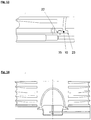
- the membrane is inflated, whereby a compression of lying on the other side of the membrane elastomer layers (1) is effected and between the membrane plate (9) and the membrane, a displacement or membrane space is formed ( Fig. 6 ).
- the membrane plate (9) has a concavely curved surface, so that when the pressure membrane (5) is stretched even without a pressure generated there is a membrane space which is formed between the underside of the flat membrane and the concave surface of the membrane plate ( Fig. 7, 8 ).
- the elastomer layer (1) may also have a concavely curved recess in the region of the contact surface with the pressure membrane (5).
- both the membrane plate (9) and the elastomer layer lying over the pressure membrane have a corresponding concave surface, so that there is a lenticular membrane or displacement space.
- the invention also provides a corresponding spring element, in which the membrane plate (9) has hydraulic supply lines (4) and connections (7) which pass through the membrane plate and open into the membrane space and can supply it with hydraulic fluid.
- these have a carrier plate (11) for the elastomer layers (1), which preferably have a recess in which the membrane plate (9) finds room as a separate part of the carrier plate.
- the membrane plate against the support plate itself be braced.
- the invention further spring elements are the same principle as described, but have special design features due to their space-saving manner.
- the invention comprises a spring element, wherein the elastic pressure membrane (5) has a circumferential end elastic T-shaped bead (10) consisting of an outer (26) and inner bead (23), and having a belonging to the hydraulic device Membrane plate (9) is connected in a pressure-tight manner in such a way that said beads are inserted into a correspondingly shaped matching T-shaped hollow profile (10 b), which is formed by a correspondingly shaped diaphragm head (9 a) and a biasing disc (21), wherein (a ) the membrane head is a part of the membrane plate (9) and is disposed within the membrane and the membrane space (12) and has a circumferential protruding lip (24) which receives the inner bead (23) of the membrane, and (b) the biasing plate a ring-like opening or recess which receives the membrane head (9a) with the pressure diaphragm
- the biasing disc (21) is wholly or partially on the membrane plate (9) except the region of the membrane head (9a) and is disposed between the first elastomer layer (1) or possibly the elastomer support plate and said membrane plate. In this case, preferably, the biasing disc (21) with the elastomer layers (1) outside the region of the pressure membrane is firmly connected.
- the membrane disc (9) is braced against the biasing disc (21) by means of fastening means, so that the T-shaped elastic bead (23, 26) of the pressure membrane is compressed.
- the pretensioning disk or plate (21) can also be a support plate for the spring element itself, wherein in this embodiment it has a precisely fitting recess in the area of the pressure membrane into which the correspondingly shaped membrane plate (9) with its correspondingly shaped membrane head (9a) is inserted and is clamped to the plate (21) by means of fastening means.
- the membrane plate (9) at least one hydraulic inlet and outlet (4, 7), wherein the hydraulic inlet through the membrane head (9a) leads and opens in the membrane space (12).
- the spring elements which occupy a smaller space, preferably have a preload space (22) which is formed in the untensioned state in the area in which outer bead (26), membrane disc (9) and biasing disc (21) meet, and the when bracing the parts (21) and (9) by pressing in bead material completely closes.
- the elastic pressure membrane (5) according to the invention should according to the invention have a certain softness and flexibility.
- Such membranes are preferably suitable for spring element according to the invention, in which a large footprint is necessary or desirable.
- the cone-shaped or parboloid membranes which are preferably used in stiffer and less flexible but elastic in terms of elongation.
- the invention thus also relates to such spring elements in which the pressure membrane (5) is stiff and has a parabolic or conical spatial shape, which with the membrane head (9a) located at the base, a correspondingly shaped cone-hat-like membrane cavity (12) or a cone cone hat ( 12a) forms.
- the invention also relates in particular to corresponding spring elements in which the elastomer layers (1) in the core of the spring element have a cone-shaped cavity correspondingly shaped to the membrane cavity (12), which is filled by the membrane cone cap (12a) formed by the pressure membrane.
- Such spring elements may be modified in such a way that the membrane cavity (12) of the Druckmembrankegelhuts (12a) has a stop device (50) which prevents overloading the system that the conical pressure membrane irreversibly collapses.
- a stop device is made of an inelastic material is preferably made in the form of a conical hat, which is centrally located in the interior of the membrane cavity (12) on the base of the membrane head (12a) and a Zulauf arrangement and a connection to the hydraulic supply line (4).
- the feed guide can also be designed in the form of an annular gap.
- the described hydraulic devices including pressure diaphragms and sealing elements can be mounted on both (the upper and lower) sides of the spring element.
- Such spring elements are particularly suitable if they must be very large, so that a pressure generated on one side can be unfavorable. In most cases, it is sufficient if the spring element is equipped only on one side with a corresponding device.
- such a spring element may be equipped such that it has on the side opposite the hydraulic device in the core region of the spring element a recess or cavity (40) in the elastomeric material which is shaped and configured to / it is separated from the diaphragm space (12) by means of a web (42) made of elastomeric material of the layers (1), so that the web can be pressed into the cavity or recess when the hydraulic pressure in the diaphragm space is increased.
- a greater variability of the adjustability of the rigidity is possible, in particular if the recess or the cavity (40) additionally has an inelastic calibration element (3, 8) with the aid of which the volume of the recess or of the cavity (4) can change.
- the described spring elements are ideally suited to be used as bearings for machines or transmissions.
- the invention thus relates to a bearing comprising at least two opposing identically aligned or arranged and thus with respect to their damping properties the same acting spring elements between which the gear or the machine is fixed, as described above, below and in the claims.
- the spring elements according to the invention are interconnected by crosswise arranged hydraulic lines (34, 35), whereby the bearings receive the properties described further.
- they can be equipped with at least one overpressure valve (31) and one throttle valve (33, 36, 37) for targeted control in systems under load, as also explained below.
- the invention is ultimately the use of the described bearing or spring element. These are intended for use in machines, but especially wind turbines, and serve here for cushioning bending, deformation and displacement forces, which occur especially in extreme load case in the vertical direction to the mounted spring elements.
- the elastomeric materials used for the layers (1) according to the invention consist essentially of a natural rubber, a natural rubber derivative or of a suitable elastic polymeric plastic or plastic mixture.
- the elastomer layer according to the invention may have different hardness ("shore hardness") and different damping properties, according to the desired requirements.
- elastomers having a hardness of 20 to 100 Shore A, in particular 30 used up to 80 Shore A are known in the art and adequately described in the relevant literature.
- the non-elastomeric intermediate plates or layers (2) are made according to the invention of largely inelastic materials with low compressibility.
- these are metal sheets, but other materials such as hard plastics, composites or carbon fiber-containing materials are used.
- the intermediate sheets and the elastomeric materials (4) are usually bonded together by vulcanization.
- the pressure membrane (5) is usually also made of natural rubber or a natural rubber derivative.
- the material must be tear and pressure resistant over a large area. It is preferably of a smooth, dense structure which has no surface pores or only very small diameter pores which are incapable of receiving microdroplets of the hydraulic fluid.
- hydraulic fluids can be used as hydraulic fluids.
- water which optionally buried antifreeze, alcohols or additives, suitable.
- hydraulic oils can be used.
- the spring element according to the invention can be used in two basic structural embodiments.
- the first embodiment is based on a flat membrane (5) occupying a relatively large area on the membrane plate (9).
- the displacement chamber, or membrane space (5) is formed above all by the inflation of the membrane lying flat on the membrane plate with simultaneous compression of the elastomer layers (1) above the pressure membrane.
- Recesses, preferably concave type, in the elastomer layer above the membrane and / or in the membrane plate (9) below the membrane can generate a displacement space already in the unpressurized state.
- the flat membrane ( Fig. 6 ) has a relatively flat, preferably lenticular shape
- the second principal embodiment is represented by the parabolic membrane or conical membrane ( Fig. 11 - 19 ), which already in the pressureless state, the said conical shape or a paraboloid.
- the membrane provides a sealing function between the fluid and the elastomeric body.
- Fig. 6 and FIGS. 11-19 represent an elastomer component with a plurality of layers (eg 4 layers).
- the special feature over conventional layer springs is that the preferably round intermediate plates (2) have a preferably central bore so that the inelastic structure is present only in the outer region.
- the core region In the inner region, the core region, only elastomer (1) is present, which preferably has a recess in has the area occupied by the membrane surface.
- the spring elements according to the invention comprise a membrane plate (9) which contains an opening for the connection of the hydraulic lines. Furthermore, the membrane plate contains an annular T-slot (10) into which the surface membrane (5) is vulcanized. In the vulcanization is the peculiarity that only in the T-groove binding occurs. The remaining area remains without bond, so that here a cavity for introducing the hydraulic medium in the membrane space (12) is formed. According to the tightness of the T-shaped connection is very important. In the prior art, this is achieved on the one hand by applying a binder into the T-groove before vulcanization, so that a rubber-metal compound is formed. This rubber-metal compound should be absolutely tight according to the prior art.
- a simple variant dispenses with its own pressure-increasing ring.
- the T-shaped groove is introduced into the membrane plate (9) and vulcanized. Thereafter, the outer region of the membrane plate is bent inwardly, thereby increasing the pressure in the region of the T-slot (10) takes place and tightness is ensured.
- This bias is about 10% to 40% of the thickness of the outer bead (26), so that a part of the volume of the outer bead is displaced to the inner bead (23), so that here also creates a bias and thus the tightness of the bead is reached.
- the outer bead (26) shifts to both sides when biased and thus pushes between the biasing ring (21) and the diaphragm plate (9) before they come together and close the gap.
- the outer bead (26) between the biasing ring (21) and diaphragm (9) would pinch.
- a preferably wedge-shaped preload clearance (22) is provided.
- This preload clearance is about 2 - 3 mm deep, ie deeper than the material flows under the given bias, so that here an undefined clamping of the elastomer from the outer bead (26) is prevented.
- the clamping can be done without additional medium.
- spring elements based on a parabolic membrane pressures of 200 to 1500 are provided due to the smaller size. The diaphragm can withstand this pressure only if it is guided cleanly and in all places into the conical cavity of the elastomer component and does not get in contact with the hard intermediate plates.
- a minimum distance (28) to the intermediate plates (2) is required. This should be at least 5 mm.
- the bias between membrane plate (9) and bias plate (21) can also be reversed so that the inner bead clamping portion of (9) is separated and can be tightened by screws ( Fig. 14 ). Again, a bias clearance (22) should be provided.
- the built-in wind turbine spring element, or such elements containing bearings work in relation to the damping of the system as follows:
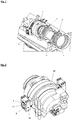
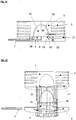
- the transmission has on both sides of a transmission-side torque arm (11) on ( Fig. 1, 2 ). This will entwined with a yoke (10).
- a yoke (10) Between the transmission-side torque arm (11) and the yoke (10) elastomer elements (06, 07, 08 and 09) are arranged.
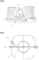
- the elastomeric elements contain a cavity which is filled with liquid. These cavities, respectively, are as in Fig. 3, 4 shown, with Hydraulikleitunegn (34, 35), which may be pipes or hoses, connected together.
- Hydraulikleitunegn 34, 35
- Both are connected to each other with the hydraulic line (34) so that no fluid movement takes place due to the pressure which arises at the same time.
- the elastomer elements (07, 09) are simultaneously relieved, so that even in the hydraulic line (35) no hydraulic fluid is moved.
- the springs thus show a stiff spring characteristic, ie they are unaffected by the hydraulic system.
- a bearing point preferably comprises two elastomeric spring systems which hold the machine part to be stored in one point (eg top and bottom) ( Fig. 1 ).
- Such an elastomeric spring system is preferably made of an elastomeric spring according to the invention, but may also consist of a whole array of correspondingly arranged springs.
- two bearing points each with two elastomer springs are used. The two bearing points are connected by hydraulic lines ( Fig.
- the elastomeric hydraulic bearing is also important for gearless systems.
- the generator is equally direct - without elastic coupling - arranged on the rotor shaft.
- the system thus has the same problem as transmission systems.
- radial displacement forces enter the rotor.
- the air gap between the seated on the rotor shaft rotor and the stator attached to the stator of the generator must be kept as small as possible for a good efficiency and is changed by the radial constraining forces occurring according to the prior art.
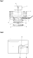
- Fig. 4 the vertical displacement is shown by machine deformation.
- the spring elements (07) and (08) experience an increase in pressure while the pressure drops in the elements (06) and (09).
- the liquid flows from the more heavily loaded upper part to the unloaded spring element (06), which causes a reduction in the resistance of the elastomeric element (08), while at the same time in the elastomeric element (06) resulting liquid reduction is refilled by the liquid from the spring element (08).
- the same principle applies between the spring elements (07) and (09), so that this vertical movement takes place with significantly smaller spring stiffness.
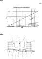
- Fig. 5 shows a diagram with the high stiffness in the torsion direction and the lower stiffness with vertical displacement of the transmission to the machine frame.
- the elastomer components are designed so that they can continue to operate without liquid.
- the valve (32) is opened automatically, so that in the connecting lines (34 and 35) the same pressure again arises, which is the case after a short time.
- the system is then back in its original state, so that the pressure switch (32) can be closed again.
- the valve function described above in addition to the vibration reduction also has the advantage that the hydraulic lines do not have to be designed for the prevailing at extreme load pressure. Furthermore, the extreme loads can be reduced by the damping occurring in the connecting line with the additional throttle (33). While the pressure relief valve (31) are effective with the throttle (33) only in extreme load case, more restrictors (36 and 37) can be arranged in the pressure and discharge side. These bring a damping in the overall system while the system works. That Any displacement of the machine frame is usually associated with vibrations of the entire system. These vibrations are damped by the existing throttles (36 and 37), which causes a load reduction in the wind turbine. The restrictors (36 and 37) may be incorporated in the form of adjustable prior art restrictors. However, it is also possible to dimension all hydraulic lines so that the throttle function is already obtained by the fluid friction in the lines.
- Elastomeric hydraulic storage can also be used in gearless systems.
- the generator is equally direct - without elastic coupling - arranged on the rotor shaft.
- the system thus has the same problem as transmission systems.
- Fig. 22 are arranged as an example 2 pairs.
- inventions can be connected to the generator - as in Fig. 22 described axially arranged.
- Figure 22 shows the arrangement of the bearing behind the generator on the side facing away from the rotor. An arrangement in front of the generator, in the direction of the rotor is also possible.
Description
Die Erfindung betrifft Federelemente und Lager, welche diese Federelement enthalten, wobei die Federsteifigkeit der Lager bzw. Federelemente sich durch verformbare Elastomerkörper, bzw. Elastomerschichten individuell durch Vorspannung einstellen lässt. Die Verformung der Elastomerschichten und damit der Federelemente wird durch eine entsprechend gestaltete Hydraulikvorrichtung erreicht. Die Dichtigkeit der erfindungsgemäßen Feder- bzw. Lagerelemente wird durch spezielle hydraulisch vorgespannte Abdichtelemente, Einsatz einer Druckmembran und spezieller konstruktiven Merkmale der Elastomerelemente erzielt. Die erfindungsgemäßen Elastomerlagerungen einschließlich ihrer Federelemente sind insbesondere zur Verwendung in Zwei- oder Mehrpunktlagerungen bei Rotor- und Getriebekonstruktionen von großen Windkraftanlagen geeignet und dienen dort dazu, Dämpfungs- und Triebstrangschwingungen abzufedern, die insbesondere zu Verschiebungs-, Verbiegungs- und Verformungskräften führen und speziell bei extremen Belastungssituationen der Anlage auftreten können.The invention relates to spring elements and bearings which contain these spring element, wherein the spring stiffness of the bearing or spring elements can be adjusted individually by biasing elastomeric bodies or elastomer layers. The deformation of the elastomer layers and thus the spring elements is achieved by a correspondingly designed hydraulic device. The tightness of the spring or bearing elements according to the invention is achieved by special hydraulically pre-stressed sealing elements, use of a pressure membrane and special structural features of the elastomer elements. The elastomeric bearings according to the invention including their spring elements are particularly suitable for use in two- or multi-point bearings in rotor and gearbox designs of large wind turbines and serve there to absorb damping and driveline vibrations, which in particular lead to displacement, bending and deformation forces and especially in extreme Stress situations of the plant can occur.
Elastische Federelemente sind bekannt und werden in vielen Bereichen der Technik vorrangig zur Dämpfung von Schwingungen und Kräften eingesetzt. Dabei hat das Federelement eine von der Art, Größe, Form und Anzahl der vorhandenen Elastomerschichten vorgegebene definierte Steifigkeit, die gegebenenfalls nach Einbau des Federelementes in einem bestimmten Rahmen variabel gestaltet werden kann.Elastic spring elements are known and are used in many areas of technology primarily for damping vibrations and forces. In this case, the spring element has a defined by the type, size, shape and number of existing elastomer layers defined stiffness, which may optionally be made variable after installation of the spring element in a certain frame.
Bei großen Windkraftanlagen mit Leistungen von mehr als zwei Megawatt greifen nicht selten insbesondere an Rotorblättern, Rotorwelle und Triebstranglagerung, aber auch an der Gondel selbst, starke Kräfte an, welche die üblicherweise verwendeten Zwei,-Drei- oder Vierpunktlagern der Getriebe und Generatoren großen Belastungen aussetzen, so dass es zu entsprechenden insbesondere auch vertikalen Verschiebungen, Verformungen, Verwindungen, Nickbewegungen der Anlage kommen kann, möglicherweise mit Beschädigungen des Materials oder einzelner Bauteile.In large wind turbines with outputs of more than two megawatts attack not infrequently especially on rotor blades, rotor shaft and drive train storage, but also on the gondola itself, strong forces that expose the commonly used two, three or four-point bearings of the gearboxes and generators large loads , so that it can lead to corresponding in particular vertical displacements, deformations, twisting, pitching movements of the plant, possibly with damage to the material or individual components.
Der Triebstrang von Windkraftanlagen wird in der Regel elastisch am Maschinenträger befestigt. Dies erfolgt aus Gründen der Körperschallisolation und auch um Verschiebungen des Systems zu ermöglichen. Üblicherweise sind die bekannten Lager mit passiven elastischen Elementen ausgestattet, die zumindest einen Teil derartiger Zwangskräfte und erzeugten Schwingungen aufgrund ihrer Ausrichtung und unterschiedlichen vorab eingestellten Steifigkeiten abfedern können.The driveline of wind turbines is usually attached elastically to the machine frame. This is done for reasons of structure-borne sound isolation and also to allow shifts in the system. Usually, the known bearings are equipped with passive elastic elements which can cushion at least part of such constraining forces and vibrations generated due to their orientation and different preset stiffnesses.
Bei sehr starken, insbesondere plötzlich und schnell auftretenden Belastungen (Extremlastfall) vor allem in vertikaler Richtung, also normalerweise in Richtung, in der die üblicherweise angeordneten elastomeren Federelemente eine hohe Federsteifigkeit aufweisen, reicht die Elastizität bzw. Steifigkeit dieser Elemente, die bezüglich ihrer regulierbaren Steifigkeit in der Regel für durchschnittliche Belastungen und üblicherweise ansetzende Kräften insbesondere auf die Triebstranglagerung ausgelegt sind, nicht aus, so dass die genannten Verformungen, Verschiebungen und Verwerfungen, die in der Anlage auftreten, zu Schäden an der Anlage, vor allem am Getriebe führen, wie im folgenden näher beschrieben.For very strong, especially sudden and fast occurring loads (extreme load case), especially in the vertical direction, ie normally in the direction in which the Usually arranged elastomeric spring elements have a high spring stiffness, the elasticity or rigidity of these elements, which are designed with respect to their adjustable stiffness usually for average loads and usually applying forces in particular on the drive train storage, not sufficient, so that said deformations, displacements and faults that occur in the system, cause damage to the system, especially at the transmission, as described in more detail below.
Zur Triebstrang-Lagerung von Windkraftanlagen werden im Stand der Technik unterschiedliche Systeme angewendet. Eines der Systeme ist die Momentenlagerung mit starrer Rotorwelle (
Nach dem Stand der Technik werden möglichst weiche Elastomerbauteile für die Getriebe-Drehmoment-Abstützung verwendet, so dass die Verschiebekräfte möglichst klein gehalten werden. Dies bewirkt jedoch auch eine große Drehbewegung des Getriebes bei Lasteinleitung, was wiederum eine Verschiebung der Getriebeausgangswelle zu der Generatorwelle bewirkt, welche nachteilig ist, so dass diese Weichheit der Elastomerbauteile nur begrenzt einsetzbar ist, oder entsprechend aufwändige Kupplungen zwischen Getriebe und Generator erforderlich werden.According to the prior art as soft as possible elastomer components are used for the transmission torque support, so that the displacement forces are kept as small as possible. However, this also causes a large rotational movement of the transmission with load application, which in turn causes a shift of the transmission output shaft to the generator shaft, which is disadvantageous, so that this softness of the elastomer components is limited, or correspondingly expensive clutches between the gear and generator are required.
Das in der
Diese Federelemente haben sich in der Praxis, obwohl sie die gewünschten technischen Effekte in Bezug auf die Dämpfung erzielen, als problematisch erwiesen, denn bei den notwendigen hohen Drücken, die erzeugt werden müssen, um die Steifigkeit in vertikaler Richtung hinreichend zu vergrößern, treten immer wieder Dichtigkeitsprobleme mit Verlust von Hydraulikflüssigkeit auf, und dies obwohl die Elastomerschichten, die von Hydraulikflüssigkeit komprimiert werden, durch Vulkanisation und / oder Verklebung fest mit den umgebenden Teilen verbunden sind.These spring elements have proven to be problematic in practice, although they achieve the desired technical effects with respect to damping, because the necessary high pressures which have to be generated in order to sufficiently increase the rigidity in the vertical direction occur again and again Leakage problems with loss of hydraulic fluid, even though the elastomer layers, which are compressed by hydraulic fluid, by vulcanization and / or bonding are firmly connected to the surrounding parts.
Bei näheren Untersuchungen und Tests mit dem in der
Überdies wurde festgestellt, dass der direkte Kontakt der hydraulischen Flüssigkeit mit dem Elastomermaterial der Federelemente unter Einwirkung hoher Drücke zu einer verminderten Haltbarkeit oder Elastizität des Elastomers führen kann, so dass die entsprechenden Federelemente unter Umständen früher ausgetauscht werden müssen.Moreover, it was found that the direct contact of the hydraulic fluid with the elastomeric material of the spring elements under reduced pressure to a reduced Durability or elasticity of the elastomer may result, so that the corresponding spring elements may need to be replaced earlier.
Es stellt sich somit die Aufgabe, entsprechende Federelemente bzw. Lager basierend auf dem Grundkonzept der
Die Aufgabe wurde gelöst durch die im folgenden und in den Ansprüchen spezifizierten Federelemente, Lager und deren Verwendung.The object has been achieved by the spring elements, bearings and their use specified below and in the claims.
Gegenstand der Erfindung ist somit ein in seiner Steifigkeit durch hydraulisch erzeugten Druck einstellbares, aus Schichten aufgebautes Federelement im wesentlichen umfassend zwei oder mehrere Elastomerschichten (1), unelastischen Zwischenschichten (2), einer oder mehrere Hydraulikvorrichtungen inklusive Abdichtungselemente (4, 7, 9, 11, 12) und gegebenenfalls unelastischen Abschlussplatten, wobei zwei Elastomerschichten durch eine unelastische Zwischenschicht oder -platte voneinander getrennt sind, und die unelastischen Schichten eine zentrisch angeordnete Öffnung oder Bohrung besitzen, so dass das Federelement zumindest im Inneren einen durchgehenden elastomeren Kern aufweist, mit dem die Elastomerschichten in Verbindung stehen, wobei - in vertikaler Richtung zu den Schichten gesehen - auf einer oder beiden Seiten des Federelements besagte Hydraulik-Vorrichtung vorgesehen ist, welche durch Verdrängung bzw. Einbringung einer hydraulischen Flüssigkeit mittels hydraulischen Drucks in das Federelement die Kompression des Elastomermaterials (1) im Kernbereich desselben in vertikaler Richtung zu den Schichten bewirkt, so dass ein Verdrängungsraum entsteht oder vergrößert wird. Dabei zeichnet sich besagtes Federelement dadurch aus, dass zwischen der Elastomerschicht im Kernbereich des Federelementes und dem Verdrängungsraum eine elastische Druckmembran (5) angeordnet ist, die an ihrem vorzugsweise äußerem Rand mit der Hydraulik-Vorrichtung oder Teilen davon fest verbunden ist, so dass ein Membranraum (12) entsteht, der zumindest bei Vorliegen eines hydraulischen Druckes dem Verdrängungsraum entspricht und hydraulische Flüssigkeit enthält, und die Hydraulik-Vorrichtung ein oder mehrere Abdichtungs-Elemente umfasst, welche eine Vorspannung aufweisen und so angeordnet sind, dass sie auf die Druckmembran im Bereich ihrer Verbindung zur Hydraulik-Vorrichtung einen erhöhten Druck gegenüber dem Druck im Membranraum erzeugen, wodurch die feste Verbindung zum hydraulische Flüssigkeit aufweisenden Membranraum selbst bei sehr hohen Drücken im Inneren des Membranraumes absolut druckdicht wird.The invention thus provides a spring element which can be adjusted in its rigidity by hydraulically generated pressure and which comprises layers comprising essentially two or more elastomer layers (1), inelastic intermediate layers (2), one or more hydraulic devices including sealing elements (4, 7, 9, 11 , 12) and optionally inelastic end plates, wherein two elastomer layers are separated by an inelastic intermediate layer or plate, and the inelastic layers have a centrally disposed opening or bore, so that the spring element at least in the interior has a continuous elastomeric core, with the Elastomer layers are connected, wherein - seen in the vertical direction to the layers - on one or both sides of the spring element said hydraulic device is provided which by displacement or introduction of a hydraulic fluid by means of hydraulic pressure in the spring element causes the compression of the elastomeric material (1) in the core region thereof in the vertical direction to the layers, so that a displacement space is created or increased. In this case, said spring element is characterized in that between the elastomer layer in the core region of the spring element and the displacement chamber an elastic pressure membrane (5) is arranged, which is firmly connected at its preferably outer edge with the hydraulic device or parts thereof, so that a membrane space (12) is formed, which corresponds at least in the presence of a hydraulic pressure to the displacement chamber and contains hydraulic fluid, and the hydraulic device comprises one or more sealing elements, which have a bias and are arranged so that they on the pressure membrane in the region Connection to the hydraulic device to generate an increased pressure against the pressure in the membrane space, whereby the solid connection to the hydraulic fluid-containing membrane space is absolutely pressure-tight even at very high pressures in the interior of the membrane space.
Generell wird erfindungsgemäß unter "Verdrängungsraum" der Raum verstanden, der durch das Einbringen einer hydraulischen Flüssigkeit in das Federelement unter Erzeugung eines hydraulischen Druckes durch Komprimieren von Elastomermaterial entsteht bzw. gegebenenfalls schon vorher vorhanden ist. Demgegenüber wird unter "Membranraum" (12) der geometrische Raum verstanden, der zwischen der Membranplatte (9) und der über dieser gespannten Druckmembran (5) gebildet wird. In der Regel, entspricht unter Druck der Membranraum im wesentlichen dem Verdrängungsraum.In general, according to the invention, the term "displacement space" is understood to mean the space which is created by introducing a hydraulic fluid into the spring element to generate a hydraulic pressure by compressing elastomer material or possibly already exists. In contrast, "membrane space" (12) is understood to mean the geometric space formed between the membrane plate (9) and the pressure membrane (5) stretched over it. As a rule, under pressure, the membrane space essentially corresponds to the displacement space.
Gegenstand der Erfindung ist insbesondere ein entsprechendes Federelement, bei dem die elastische Druckmembran (5) auf einer zur Hydraulik-Vorrichtung gehörenden Membranplatte (9) aufliegt, und an ihrem Rand mit dieser über einen elastischen Wulst (10), der eine T-Nut förmige Aussparung (10a) in der Membranplatte ausfüllt, verbunden ist, und ein unelastisches Druckerhöhungselement (6), vorzugsweise ein Profilring, zwischen Elastomerschicht (1) und der Druckmembran im Bereich ihres Wulstes angeordnet ist, welches ein entsprechend geformtes Profil besitzt, das bei Vorspannung, welche einem höheren Druck zu entsprechen hat als der Druck im Membranraum (12), in das elastische Material im Bereich des Wulstes der Druckmembran gepresst wird, und somit zu einer gezielten Abdichtung im Bereich der T-Nut der Membranplatte führt.The invention relates in particular to a corresponding spring element, in which the elastic pressure membrane (5) rests on a diaphragm belonging to the hydraulic device (9), and at its edge with this via an elastic bead (10), the T-groove shaped Recess (10a) in the membrane plate fills, is connected, and an inelastic pressure increasing element (6), preferably a profile ring, between the elastomer layer (1) and the pressure membrane in the region of its bead is arranged, which has a correspondingly shaped profile which, when prestressed, which has to correspond to a higher pressure than the pressure in the membrane space (12), is pressed into the elastic material in the region of the bead of the pressure membrane, and thus leads to a targeted sealing in the T-groove of the membrane plate.
Ferner hat sich gezeigt, dass die Abdichtung besonders vorteilhaft, stabil und komplett ist, wenn zwischen Druckerhöhungselement (6) und elastischem Wulst (10) der Druckmembran ein Vorspannfreiraum (10c) zur Verfügung gestellt wird, der durch eine entsprechende, vorzugsweise keilförmige Aussparung im Material der Abdichtungselemente bzw. der entsprechenden Teile der Hydraulikvorrichtung gebildet werden kann.Furthermore, it has been found that the seal is particularly advantageous, stable and complete when between the pressure increasing element (6) and elastic bead (10) of the pressure membrane, a preload clearance (10c) is provided by a corresponding, preferably wedge-shaped recess in the material the sealing elements or the corresponding parts of the hydraulic device can be formed.
In einer besonders einfachen Ausführungsform wird auf das Druckerhöhungselement (6), beispielsweise den Profilring verzichtet und funktionell durch die Membranplatte (9) ersetzt, welche in diesem Fall aber im Bereich der T-Nut verpresst ist, so dass es lokal zu einem erhöhten Druck kommt, was zu einer stärkeren Abdichtung in diesem Bereich führt (
In den Ausführungsformen der Abbildungen 6, 7 und 8 ist die Membran typischer weise eine Rundmembran, welche flach auf der Membranplatte (9) aufliegt. Durch entsprechende Einleitung einer hydraulischen Flüssigkeit wird die Membran aufgebläht, wodurch eine Kompression der auf der anderen Seite der Membran liegenden Elastomerschichten (1) bewirkt wird und zwischen Membranplatte (9) und der Membran ein Verdrängungs- bzw. Membranraum entsteht (
In einer weiteren Ausführungsform kann auch die Elastomerschicht (1) im Bereich der Berührungsfläche mit der Druckmembran (5) eine konkav gekrümmte Aussparung besitzen.In a further embodiment, the elastomer layer (1) may also have a concavely curved recess in the region of the contact surface with the pressure membrane (5).
In einer besonders vorteilhaften Ausführungsform weist sowohl die Membranplatte (9) als auch die über der Druckmembran liegende Elastomerschicht eine entsprechnd konkave Oberfläche auf, so dass ein linsenförmiger Membran- bzw.Verdrängungsraum vorliegt.In a particularly advantageous embodiment, both the membrane plate (9) and the elastomer layer lying over the pressure membrane have a corresponding concave surface, so that there is a lenticular membrane or displacement space.
Gegenstand der Erfindung ist auch ein entsprechendes Federelement, bei dem die Membranplatte (9) Hydraulikzuleitungen (4) und -anschlüsse (7) aufweist, welche durch die Membranplatte hindurchführen und in den Membranraum münden und diesen mit Hydraulikflüssigkeit versorgen können.The invention also provides a corresponding spring element, in which the membrane plate (9) has hydraulic supply lines (4) and connections (7) which pass through the membrane plate and open into the membrane space and can supply it with hydraulic fluid.
In einer weiteren Ausführungsreihe der erfindungsgemäßen Federelemente weisen diese eine Trägerplatte (11) für die Elastomerschichten (1) auf, welche vorzugsweise eine Aussparung besitzen, in der die Membranplatte (9) als separater Teil der Trägerplatte Platz findet.In a further execution series of the spring elements according to the invention, these have a carrier plate (11) for the elastomer layers (1), which preferably have a recess in which the membrane plate (9) finds room as a separate part of the carrier plate.
In einer besonderen Ausführungsform kann bei dieser Lösung auch die Membranplatte gegenüber der Trägerplatte selbst verspannt sein.In a particular embodiment, in this solution, the membrane plate against the support plate itself be braced.
Gegenstand der Erfindung sind ferner Federelemente gleichen Prinzips wie beschrieben, die aber aufgrund ihrer Platz sparenden Weise besondere konstruktive Merkmale aufweisen. So umfasst die Erfindung ein Federelement, bei dem die elastische Druckmembran (5) einen umlaufenden endständigen elastischen T-förmigen Wulst (10), bestehend aus einem äußeren (26) und inneren Wulst (23), aufweist und mit einer zur Hydraulik-Vorrichtung gehörenden Membranplatte (9) auf die Weise druckdicht verbunden ist, dass besagte Wulste in ein entsprechend geformtes passendes T-förmiges Hohlprofil (10b) eingelegt sind, welches von einem entsprechend geformten Membrankopf (9a) und einer Vorspannscheibe (21) gebildet wird, wobei (a) der Membrankopf ein Teil der Membranplatte (9) ist und innerhalb der Membran und des Membranraumes (12) angeordnet ist sowie eine umlaufenden überstehende Lippe (24) besitzt, welche den inneren Wulst (23) der Membran aufnimmt, und (b) die Vorspannplatte eine ringartige Öffnung bzw. Aussparung aufweist, welche den Membrankopf (9a) mit der Druckmembran passgenau aufnimmt, und der Rand der Öffnung / Aussparung von einer überstehenden Lippe gebildet wird, welche den äußeren elastischen Wulst (26) der Membran aufnimmt.The invention further spring elements are the same principle as described, but have special design features due to their space-saving manner. Thus, the invention comprises a spring element, wherein the elastic pressure membrane (5) has a circumferential end elastic T-shaped bead (10) consisting of an outer (26) and inner bead (23), and having a belonging to the hydraulic device Membrane plate (9) is connected in a pressure-tight manner in such a way that said beads are inserted into a correspondingly shaped matching T-shaped hollow profile (10 b), which is formed by a correspondingly shaped diaphragm head (9 a) and a biasing disc (21), wherein (a ) the membrane head is a part of the membrane plate (9) and is disposed within the membrane and the membrane space (12) and has a circumferential protruding lip (24) which receives the inner bead (23) of the membrane, and (b) the biasing plate a ring-like opening or recess which receives the membrane head (9a) with the pressure diaphragm accurately, and the edge of the opening / recess of a protruding lip t, which receives the outer elastic bead (26) of the membrane.
In einer besonderen Ausführungsform liegt die Vorspannscheibe (21) ganz oder teilweise auf der Membranplatte (9) außer dem Bereich des Membrankopfes (9a) auf und ist zwischen der ersten Elastomerschicht (1) oder ggf. der Elastomerträgerplatte und besagter Membranplatte angeordnet. In diesem Fall ist vorzugsweise die Vorspannsscheibe (21) mit den Elastomerschichten (1) außerhalb des Bereiches der Druckmembran fest verbunden.In a particular embodiment, the biasing disc (21) is wholly or partially on the membrane plate (9) except the region of the membrane head (9a) and is disposed between the first elastomer layer (1) or possibly the elastomer support plate and said membrane plate. In this case, preferably, the biasing disc (21) with the elastomer layers (1) outside the region of the pressure membrane is firmly connected.
Ferner ist vorzugsweise die Membranscheibe (9) gegen die Vorspannscheibe (21) mittels Befestigungsmitteln verspannt, so dass der T-förmige elastische Wulst (23, 26) der Druckmembran komprimiert wird.Further, preferably, the membrane disc (9) is braced against the biasing disc (21) by means of fastening means, so that the T-shaped elastic bead (23, 26) of the pressure membrane is compressed.
Die Vorspannscheibe oder -platte (21) kann erfindungsgemäß auch Trägerplatte für das Federelement selbst sein, wobei bei dieser Ausführung sie im Bereich der Druckmembran eine passgenaue Aussparung besitzt, in welche die entsprechend geformte Membranplatte (9) mit ihrem entsprechend geformten Membrankopf (9a) eingesetzt und mit der Platte (21) mittels Befestigungsmitteln verspannt wird.According to the invention, the pretensioning disk or plate (21) can also be a support plate for the spring element itself, wherein in this embodiment it has a precisely fitting recess in the area of the pressure membrane into which the correspondingly shaped membrane plate (9) with its correspondingly shaped membrane head (9a) is inserted and is clamped to the plate (21) by means of fastening means.
Im allgemeinen weist in den betreffenden Ausführungsformen die Membranplatte (9) mindestens einen Hydraulikzulauf und -Anschluss (4, 7) auf, wobei der Hydraulikzulauf durch den Membrankopf (9a) führt und im Membranraum (12) mündet.In general, in the relevant embodiments, the membrane plate (9) at least one hydraulic inlet and outlet (4, 7), wherein the hydraulic inlet through the membrane head (9a) leads and opens in the membrane space (12).
Auch die Federelemente, die einen kleineren Bauraum einnehmen, weisen vorzugsweise einen Vorspannfreiraum (22) auf, der im ungespannten Zustand gebildet wird im Bereich, in dem äußerer Wulst (26), Membranscheibe (9) und Vorspannscheibe (21) zusammentreffen, und der sich bei Verspannen der Teile (21) und (9) durch Hineindrücken von Wulstmaterial vollständig schließt.The spring elements, which occupy a smaller space, preferably have a preload space (22) which is formed in the untensioned state in the area in which outer bead (26), membrane disc (9) and biasing disc (21) meet, and the when bracing the parts (21) and (9) by pressing in bead material completely closes.
Die elastische Druckmembran (5) gemäß der Erfindung sollte erfindungsgemäß eine gewisse Weichheit und Flexibilität haben. Solche Membranen sind vorzugsweise für erfindungsgemäße Federelement geeignet, bei denen eine große Grundfläche notwendig oder erwünscht ist. Bei Federelementen, die nicht viel Platz einnehmen dürfen, sind solche großflächigen Druckmembranen nicht erwünscht und werden erfindungsgemäß durch die kegelförmigen bzw. parboloiden Membranen ersetzt, die vorzugsweise in steifer und wenig flexibler aber bezüglich Dehnung elastischer Ausführung eingesetzt werden. Gegenstand der Erfindung sind somit auch solche Federelemente, bei denen die Druckmembran (5) steif ist und eine paraboloide oder kegelförmige Raumform aufweist, welche mit dem an der Basis befindlichen Membrankopf (9a) einen entsprechend geformten kegelhutartigen Membranhohlraum (12) bzw. einen Membrankegelhut (12a) bildet.The elastic pressure membrane (5) according to the invention should according to the invention have a certain softness and flexibility. Such membranes are preferably suitable for spring element according to the invention, in which a large footprint is necessary or desirable. In the case of spring elements which are not allowed to occupy much space, such large-area pressure membranes are undesirable and are replaced according to the invention by the cone-shaped or parboloid membranes, which are preferably used in stiffer and less flexible but elastic in terms of elongation. The invention thus also relates to such spring elements in which the pressure membrane (5) is stiff and has a parabolic or conical spatial shape, which with the membrane head (9a) located at the base, a correspondingly shaped cone-hat-like membrane cavity (12) or a cone cone hat ( 12a) forms.
Gegenstand der Erfindung sind insbesondere auch entsprechende Federelemente bei denen die Elastomerschichten (1) im Kern des Federelementes eine dem Membranhohlraum (12) entsprechend geformte kegelförmige Kavität besitzen, welche von dem von der Druckmembran gebildeten Membrankegelhut (12a) ausgefüllt wird. Derartige Federelemente können in der Weise modifiziert werden, dass der Membranhohlraum (12) des Druckmembrankegelhuts (12a) eine Anschlagvorrichtung (50) aufweist, welche bei Überlastung des Systems verhindert, dass die kegelförmige Druckmembran irreversibel kollabiert. Eine solche Anschlagvorrichtung ist aus einem unelastischen Material vorzugsweise in Form eines Kegelhutes gefertigt ist, welcher zentral im Inneren des Membranhohlraums (12) auf der Grundfläche des Membrankopfes (12a) angeordnet ist und eine Zulaufführung sowie einen Anschluss zur Hydraulikzuleitung (4) aufweist. Die Zulaufführung kann auch in Form eines Ringspaltes ausgeführt sein.The invention also relates in particular to corresponding spring elements in which the elastomer layers (1) in the core of the spring element have a cone-shaped cavity correspondingly shaped to the membrane cavity (12), which is filled by the membrane cone cap (12a) formed by the pressure membrane. Such spring elements may be modified in such a way that the membrane cavity (12) of the Druckmembrankegelhuts (12a) has a stop device (50) which prevents overloading the system that the conical pressure membrane irreversibly collapses. Such a stop device is made of an inelastic material is preferably made in the form of a conical hat, which is centrally located in the interior of the membrane cavity (12) on the base of the membrane head (12a) and a Zulaufführung and a connection to the hydraulic supply line (4). The feed guide can also be designed in the form of an annular gap.
Generell können die beschriebenen Hydraulikvorrichtungen inklusive Druckmembranen und Abdichtungselementen auf beiden (der oberen und unteren) Seiten des Federelementes angebracht sein. Solche Federelemente sind insbesondere dann geeignet, wenn sie sehr groß sein müssen, so dass ein einseitig erzeugter Druck ungünstig sein kann. In den meisten Fällen reicht es aus, wenn das Federelement nur auf einer Seite mit einer entsprechenden Vorrichtung ausgerüstet ist.In general, the described hydraulic devices including pressure diaphragms and sealing elements can be mounted on both (the upper and lower) sides of the spring element. Such spring elements are particularly suitable if they must be very large, so that a pressure generated on one side can be unfavorable. In most cases, it is sufficient if the spring element is equipped only on one side with a corresponding device.
In solchen Fällen kann ein solches Federelement derart ausgestattet sein, dass es auf der der Hydraulik-Vorrichtung gegenüberliegenden Seite im Kernbereich des Federelementes eine Aussparung oder einen Hohlraum (40) im Elastomermaterial aufweist, welche(r) so geformt und ausgestaltet ist, dass sie/er mittels eines Steges (42) aus Elastomermaterial der Schichten (1) von dem Membranraum (12) getrennt ist, so dass der Steg bei Erhöhung des hydraulischen Druckes im Membranraum in den Hohlraum bzw. die Aussparung gedrückt werden kann. Hierdurch ist eine größere Variabilität der Einstellbarkeit der Steifigkeit möglich, insbesondere, wenn die Aussparung bzw. der Hohlraum (40) noch zusätzlich ein unelastisches Kalibrierungselement (3, 8) aufweist, mit dessen Hilfe sich das Volumen der Aussparung bzw. des Hohlraums (4) verändern lässt.In such cases, such a spring element may be equipped such that it has on the side opposite the hydraulic device in the core region of the spring element a recess or cavity (40) in the elastomeric material which is shaped and configured to / it is separated from the diaphragm space (12) by means of a web (42) made of elastomeric material of the layers (1), so that the web can be pressed into the cavity or recess when the hydraulic pressure in the diaphragm space is increased. As a result, a greater variability of the adjustability of the rigidity is possible, in particular if the recess or the cavity (40) additionally has an inelastic calibration element (3, 8) with the aid of which the volume of the recess or of the cavity (4) can change.
Die beschrieben Federelemente sind bestens geeignet, als Lager für Maschinen oder Getriebe eingesetzt zu werden. Gegenstand der Erfindung ist somit eine Lagerung, umfassend mindestens zwei gegenüberliegende gleichartig ausgerichtete oder angeordnete und somit in Bezug auf ihre Dämpfungseigenschaften gleich wirkende Federelemente, zwischen denen das Getriebe bzw. die Maschine befestigt ist, wie oben, unten und in den Ansprüchen beschrieben. Um eine optimale Dämpfungswirkung zu erzielen, sind die erfindungsgemäßen Federelemente durch kreuzweise angeordnete Hydraulikleitungen (34, 35) miteinander verbunden, wodurch die Lager die weiter beschriebenen Eigenschaften erhalten. Ferner können sie mit mindestens einem Überdruckventil (31) und einem Drosselventil (33, 36, 37) ausgestattet sein zur gezielten Steuerung bei unter Last stehenden Anlagen, wie ebenfalls nachfolgend erläutert.The described spring elements are ideally suited to be used as bearings for machines or transmissions. The invention thus relates to a bearing comprising at least two opposing identically aligned or arranged and thus with respect to their damping properties the same acting spring elements between which the gear or the machine is fixed, as described above, below and in the claims. In order to achieve an optimal damping effect, the spring elements according to the invention are interconnected by crosswise arranged hydraulic lines (34, 35), whereby the bearings receive the properties described further. Furthermore, they can be equipped with at least one overpressure valve (31) and one throttle valve (33, 36, 37) for targeted control in systems under load, as also explained below.
Gegenstand der Erfindung ist letztlich die Verwendung der geschilderten Lager bzw. Federelements. Diese sind zur Verwendung in Maschinen, insbesondere aber Windkraftanlagen vorgesehen, und dienen hier zur Abfederung von Verbiegungs-, Verformungs- und Verschiebungskräften, welche insbesondere im Extremlastfall in vertikaler Richtung zu den montierten Federelementen auftreten.The invention is ultimately the use of the described bearing or spring element. These are intended for use in machines, but especially wind turbines, and serve here for cushioning bending, deformation and displacement forces, which occur especially in extreme load case in the vertical direction to the mounted spring elements.
Im folgenden werden die Abbildungen kurz erläutert:
Ebenso werden die im Text, in den Ansprüchen und in den Abbildungen verwendeten Bezugsgrößen erläutert:
Die für die erfindungsgemäßen Schichten (1) verwendeten Elastomermaterialien bestehen im wesentlichen aus einem Naturkautschuk, einem Naturkautschukderivat oder aus einem geeigneten elastischen polymeren Kunststoff oder Kunststoffgemisch. Die Elastomerschicht kann erfindungsgemäß unterschiedliche Härte ("Shore-Härte") und unterschiedliche Dämpfungseigenschaften aufweisen, entsprechend den gewünschten Anforderungen. Vorzugsweise werden Elastomere mit einer Härte von 20 bis 100 Shore A, insbesondere 30 bis 80 Shore A verwendet. Die Herstellung derartiger Elastomere unterschiedlicher Härte ist im Stand der Technik bekannt und in der einschlägigen Literatur hinreichend beschrieben.The elastomeric materials used for the layers (1) according to the invention consist essentially of a natural rubber, a natural rubber derivative or of a suitable elastic polymeric plastic or plastic mixture. The elastomer layer according to the invention may have different hardness ("shore hardness") and different damping properties, according to the desired requirements. Preferably, elastomers having a hardness of 20 to 100 Shore A, in particular 30 used up to 80 Shore A. The preparation of such elastomers of different hardness is known in the art and adequately described in the relevant literature.
Die nicht-elastomeren Zwischenplatten bzw. -schichten (2) sind erfindungsgemäß aus weitestgehend unelastischen Werkstoffen mit geringer Kompressibilität gefertigt. Vorzugsweise sind dies Metallbleche, aber auch andere Materialien, wie harte Kunststoffe, Verbundwerkstoffe oder karbonfaserhaltige Werkstoffe sind einsetzbar. Die Zwischenbleche und die Elastomermaterialien (4) werden in der Regel durch Vulkanisierung miteinander verbunden.The non-elastomeric intermediate plates or layers (2) are made according to the invention of largely inelastic materials with low compressibility. Preferably, these are metal sheets, but other materials such as hard plastics, composites or carbon fiber-containing materials are used. The intermediate sheets and the elastomeric materials (4) are usually bonded together by vulcanization.
Die Druckmembran (5) ist in der Regel ebenfalls aus Naturkautschuk oder einem Naturkautschukderivat gefertigt. Das Material muss über einen großen Bereich reiß- und druckfest sein. Vorzugweise ist es von glatter, dichter Struktur, welche keine Oberflächen-Poren, oder nur Poren mit sehr kleinem Durchmesser aufweist, die keine Mikrotröpfchen der hydraulischen Flüssigkeit aufzunehmen vermögen.The pressure membrane (5) is usually also made of natural rubber or a natural rubber derivative. The material must be tear and pressure resistant over a large area. It is preferably of a smooth, dense structure which has no surface pores or only very small diameter pores which are incapable of receiving microdroplets of the hydraulic fluid.
Als hydraulische Flüssigkeiten können generell alle üblichen druckstabilen Flüssigkeiten verwendet werden. Für Windkraftanlagen ist beispielsweise auch Wasser, dem gegebenenfalls Gefrierschutzmittel, Alkohole oder Additive beigesetzt sind, geeignet. Ebenso können auch Hydrauliköle Anwendung finden.In general, all common pressure-stable fluids can be used as hydraulic fluids. For wind turbines, for example, water, which optionally buried antifreeze, alcohols or additives, suitable. Likewise, hydraulic oils can be used.
Das erfindungsgemäße Federelement kann in zwei prinzipiellen konstruktiven Ausführungsformen eingesetzt werden. Die erste Ausführungsform basiert auf einer Flachmembran (5), die eine relative große Fläche auf der Membranplatte (9) einnimmt. Der Verdrängungsraum, bzw. Membranraum (5) wird vor allem durch das Aufblähen der auf der Membranplatte flach aufliegenden Membran bei gleichzeitiger Komprimierung der Elastomerschichten (1) oberhalb der Druckmembran gebildet. Aussparungen, vorzugsweise konkaver Art, in der Elastomerschicht oberhalb der Membran und / oder in der Membranplatte (9) unterhalb der Membran können einen Verdrängungsraum bereits im drucklosen Zustand generieren. Während die Flachmembran (
Die erfindungsgemäßen Federelemente umfassen eine Membranplatte (9), welche eine Öffnung für den Anschluss der Hydraulikleitungen enthält. Weiterhin enthält die Membranplatte eine ringförmige T-Nut (10) in welche die Flächenmembran (5) einvulkanisiert wird. Bei der Vulkanisation besteht die Besonderheit, dass lediglich im Bereich der T-Nut eine Bindung erfolgt. Der restliche Bereich bleibt ohne Bindung, sodass hier ein Hohlraum zum Einbringen des Hydraulikmediums in den Membranraum (12) entsteht. Erfindungsgemäß ist die Dichtigkeit der T-förmigen Verbindung sehr wichtig. Im Stande der Technik wird diese zum einen dadurch erreicht, dass ein Bindemittel in die T-Nut vor der Vulkanisation aufgetragen wird, sodass eine Gummi-Metall-Verbindung entsteht. Diese Gummi-Metall-Verbindung soll nach dem Stand der Technik absolut dicht sein. Wie bereits oben im Detail geschildert, haben Praxistests, die dieser Erfindung zugrunde liegen, jedoch gezeigt, dass dies nicht der Fall ist, weil die von dem Erfinder aufgefundene Tröpfchenwanderung dafür verantwortlich ist und dazu führt, dass bei dynamischer Belastung das Bindemittel zwischen Gummi und Metall mikrometerweise abgesprengt wird. Daraus wird deutlich, dass an diesen Stellen ein höherer Druck als in den anderen Bereichen erzeugt werden muss, um Dichtigkeit zu erreichen. Dieser höherer Druck wird gemäß der Erfindung durch den Druckerhöhungsring (6) erreicht. Dieser liegt auf der Membran und bekommt aufgrund des hohen Druckes und der größeren oberen Fläche einen Vordruck, mit dem er sich in die T-Nut der Membran hineinpressen kann und somit im T-förmigen Bereich (10) eine Druckerhöhung erzeugt, wodurch das Absprengen des Bindemittels durch eindringende hydraulische Flüssigkeit verhindert wird. Der Druckerhöhungsring kann dabei in den verschiedensten Ausführungsformen gestaltet sein. Letztlich ist entscheidend, dass der Druck in dem Bereich durch eine Vorspannung vergrößert wird.The spring elements according to the invention comprise a membrane plate (9) which contains an opening for the connection of the hydraulic lines. Furthermore, the membrane plate contains an annular T-slot (10) into which the surface membrane (5) is vulcanized. In the vulcanization is the peculiarity that only in the T-groove binding occurs. The remaining area remains without bond, so that here a cavity for introducing the hydraulic medium in the membrane space (12) is formed. According to the tightness of the T-shaped connection is very important. In the prior art, this is achieved on the one hand by applying a binder into the T-groove before vulcanization, so that a rubber-metal compound is formed. This rubber-metal compound should be absolutely tight according to the prior art. However, as described in detail above, practical tests underlying this invention have shown that this is not the case because the droplet migration found by the inventor is responsible for this and results in the bond between rubber and metal under dynamic loading is demulsed micrometer-wise. It is clear that at these points, a higher pressure than in the other areas must be generated in order to achieve tightness. This higher pressure is achieved according to the invention by the pressure increasing ring (6). This lies on the membrane and gets due to the high pressure and the larger upper surface of a form with which he can press into the T-slot of the membrane and thus in the T-shaped region (10) generates an increase in pressure, causing the bursting of Binder is prevented by penetrating hydraulic fluid. The pressure increasing ring can be designed in various embodiments. Ultimately, it is crucial that the pressure in the area is increased by a bias voltage.
Eine einfache Variante verzichtet auf einen eigenen Druckerhöhungsring. Bei diesen in
Bei den Ausführungsformen der Flachmembran-Federelemente (
Das ermöglicht einen geringeren Einbauraum und reduziert die Kosten der Teile. Gleichzeitig entstehen jedoch höhere Drücke aufgrund der kleineren Fläche bei gleicher Last. Zur dichten Befestigung der Parabelmembran an der Membranplatte (9) wird diese mit zwei Wulsten verklemmt. Dazu wird die Parabelmembran (25) wie ein Reifen über die Innerer- Wulst-Klemmring-Lippe (24) des Membrankopfes (9a) gezogen, so dass der innere Wulst (23) annähernd luftfrei hinter der Lippe (24) mit leichter Vorspannung eingebracht ist. Anschließend wird die Membranplatte (9) mit dem Vorspannring (21) verschraubt. Der äußere Wulst (26) hat jedoch ein deutlich größeres Maß als der Hohlraum zwischen (21) und (9), so dass sich hier eine Vorspannung ergibt. Diese Vorspannung beträgt ca. 10 % bis 40 % der Dicke des äußeren Wulstes (26), so dass ein Teil des Volumens des äußeren Wulstes zum inneren Wulst (23) verschoben wird, so dass auch hier eine Vorspannung entsteht und somit die Dichtigkeit des Wulstes erreicht wird. Bei dieser Art von Konstruktion kann das Problem auftreten, dass der äußere Wulst (26) sich beim Vorspannen nach beiden Seiten verschiebt und er sich somit zwischen den Vorspannring (21) und die Membranplatte (9) schiebt, bevor diese zusammenkommen und den Spalt verschließen. Somit würde sich der äußere Wulst (26) zwischen Vorspannring (21) und Membran (9) einklemmen. Um das zu verhindern, wird ein, vorzugsweise keilförmiger Vorspannfreiraum (22) vorgesehen. Dieser Vorspannfreiraum ist ca. 2 - 3 mm tief, d.h. tiefer als das Material unter der gegebenen Vorspannung fließt, so dass hier ein undefiniertes Einklemmen des Elastomers aus dem äußeren Wulst (26) verhindert wird. Die Klemmung kann ohne Zusatzmedium erfolgen. Zur sichereren Befestigung ist es auch möglich, Kleber in die Fugenflächen mit einzubringen, so dass hier eine noch größere Sicherheit der Dichtigkeit gewährleistet wird. Bei Federelementen basierend auf einer Parabolmembran sind aufgrund der geringeren Baugröße Drücke von 200 bis 1500 bar vorgesehen. Die Membran kann diesem Druck nur widerstehen, wenn sie sauber und an allen Stellen in den kegelförmigen Hohlraum des Elastomerbauteiles geführt wird und keinen Kontakt mit den harten Zwischenblechen bekommt. Im Betrieb der Membran wird diese sich soweit ausdehnen, dass der Elastomerraum innerhalb der zentrischen Bohrungen der Zwischenbleche (2) weitestgehend, d.h. zu etwa 80 % verdrängt wird, so dass die Membran relativ nahe an die Zwischenbleche kommt. Deshalb ist ein Mindestabstand (28) zu den Zwischenblechen (2) erforderlich. Dieser sollte mindestens 5 mm betragen. Die Vorspannung zwischen Membranplatte (9) und Vorspannplatte (21) kann auch so umgekehrt werden, dass der innere Wulst-Klemmungs- Bereich von (9) getrennt ist und mittels Schrauben beigezogen werden kann (
Die in eine Windkraftanlage eingebauten Federelement, bzw. solche Elemente enthaltenden Lagerungen funktionieren in Bezug auf die Dämpfung der Anlage wie folgt: Das Getriebe weist beidseitig eine getriebeseitige Drehmomentstütze (11) auf (
Wie bereits erwähnt, sind die beschriebenen erfindungsgemäßen Federelemente besonders geeignet für einen Einsatz als Lagerpunkte in Zwei-, Vier- oder Mehrpunktlagerungen, vorzugsweise in Windkraftanlagen. Ein Lagerpunkt umfasst vorzugsweise zwei Elastomerfeder-Systeme, die das zu lagernde Maschinenteil in einem Punkt halten (z.B. oben und unten) (
Die elastomerhydraulische Lagerung ist ebenso für getriebelose Anlagen von Wichtigkeit. Bei diesen Anlagen ist der Generator gleichermaßen direkt - ohne elastische Kupplung- auf der Rotorwelle angeordnet. Das System hat damit die gleiche Problematik wie Getriebe Anlagen. Auch hier gehen radiale Verschiebekräfte in den Rotor ein. Der Luftspalt zwischen dem auf der Rotorwelle sitzenden Rotor und dem am Chassis befestigten Stator des Generators muss für einen guten Wirkungsgrad möglichst klein gehalten werden und wird jedoch durch die nach dem Stand der Technik auftretenden radialen Zwangskräfte verändert.The elastomeric hydraulic bearing is also important for gearless systems. In these systems, the generator is equally direct - without elastic coupling - arranged on the rotor shaft. The system thus has the same problem as transmission systems. Here too, radial displacement forces enter the rotor. The air gap between the seated on the rotor shaft rotor and the stator attached to the stator of the generator must be kept as small as possible for a good efficiency and is changed by the radial constraining forces occurring according to the prior art.
Die neben der unerwünschten Verschiebung auftretenden Zwangskräfte verhalten sich wie beim Getriebe.The coercive forces occurring in addition to the undesired shift behave as in the transmission.
In
Um die großen Steifigkeitsverhältnisse zu erreichen sind möglichst viele Schichten (Idealerweise 5 bis 10Schichten)erforderlich. Da mit großer Schichtanzahl auch die radiale Steifigkeit sinkt, neigen die Bauteile bei den in seltenen Fällen auftretenden besonders hohen Extremlasten zum radialen Ausknicken. Um das zu verhindern, ist ein Zwischenblech im mittleren bereich der Elemente Pos. 53 (
Im Extremlastfall treten, wie bereits dargelegt, deutlich höhere Drehmomente auf als im Normalbetrieb. Der Extremlastfall beschreibt eine kritische Situation der Windkraftanlage. Das erfindungsgemäße System sieht vor, dass zwischen der durch Drehmoment beaufschlagten Druckleitung (34) in der in diesem Zustand unter schwachem Druck stehenden Entlastungsseite (35) Überdruckventil (31) gebaut wird. Tritt nun in dem selten vorkommenden Extremlastfall ein hoher Druck in der Druckleitung (34) auf, so wird das Überdruckventil (31) geöffnet. Damit strömt die Flüssigkeit aus der druckbeaufschlagten Leitung (34) in die Leitung (35) mit weniger Druck. Die Fließgeschwindigkeit in dieser Leitung wird durch die Drossel (33) gebremst, so dass hier eine starke Dämpfungsfunktion entsteht. Somit werden die bei der Extremlast auftretenden Lasten der Windkraftanlage mit Hilfe der Ventilfunktion (31) der Drossel (33) reduziert. Die Elastomerbauteile sind so ausgelegt, dass sie auch ohne Flüssigkeit weiter betrieben werden können. Bei dem nächsten Stillstand, der intervallmäßig auftritt oder nach einem Extremlastfall eingeleitet wird, wird das Ventil (32) automatisch geöffnet, so dass in den Verbindungsleitungen (34 und 35) wieder gleicher Druck entsteht, was nach kurzer Zeit der Fall ist. Das System ist anschließend wieder im Ursprungszustand, so dass der Druckschalter (32) wieder geschlossen werden kann.In extreme load case occur, as already stated, significantly higher torques than in normal operation. The extreme load case describes a critical situation of the wind turbine. The system according to the invention provides that pressure relief valve (31) is built between the pressure line (34) acted upon by torque in the relief side (35) under weak pressure in this state. Now occurs in the rarely occurring extreme load case, a high pressure in the pressure line (34), it will Overpressure valve (31) opened. Thus, the liquid flows from the pressurized line (34) into the line (35) with less pressure. The flow velocity in this line is braked by the throttle (33), so that here creates a strong damping function. Thus, the loads occurring at the extreme load of the wind turbine by means of the valve function (31) of the throttle (33) are reduced. The elastomer components are designed so that they can continue to operate without liquid. At the next standstill, which occurs at intervals or is initiated after an extreme load case, the valve (32) is opened automatically, so that in the connecting lines (34 and 35) the same pressure again arises, which is the case after a short time. The system is then back in its original state, so that the pressure switch (32) can be closed again.
Die oben beschriebene Ventilfunktion hat neben der Schwingungsreduzierung auch den Vorteil, dass die Hydraulikleitungen nicht für den bei Extremlast vorherrschenden Druck ausgelegt werden müssen. Ferner können die Extremlasten durch die auftretende Dämpfung in der Verbindungsleitung mit der zusätzlichen Drossel (33) reduziert werden. Während das Überdruckventil (31) mit der Drossel (33) nur im Extremlastfall wirksam sind, können weitere Drosseln (36 und 37) in der Druck- und Entlastungsseite angeordnet. Diese bringen eine Dämpfung in das Gesamtsystem, während die Anlage arbeitet. D.h. jede Verschiebung des Maschinenrahmens ist in der Regel mit Schwingungen der gesamten Anlage in Verbindung zu bringen. Diese Schwingungen werden durch die vorhandenen Drosseln (36 und 37) gedämpft, was eine Lastreduzierung in der Windkraftanlage erwirkt. Die Drosseln (36 und 37) können in Form von einstellbaren Drosseln nach dem Stand der Technik eingebaut werden. Es ist jedoch auch möglich, alle Hydraulikleitungen so zu dimensionieren, dass die Drosselfunktion bereits durch die Flüssigkeitsreibung in den Leitungen erwirkt wird.The valve function described above, in addition to the vibration reduction also has the advantage that the hydraulic lines do not have to be designed for the prevailing at extreme load pressure. Furthermore, the extreme loads can be reduced by the damping occurring in the connecting line with the additional throttle (33). While the pressure relief valve (31) are effective with the throttle (33) only in extreme load case, more restrictors (36 and 37) can be arranged in the pressure and discharge side. These bring a damping in the overall system while the system works. That Any displacement of the machine frame is usually associated with vibrations of the entire system. These vibrations are damped by the existing throttles (36 and 37), which causes a load reduction in the wind turbine. The restrictors (36 and 37) may be incorporated in the form of adjustable prior art restrictors. However, it is also possible to dimension all hydraulic lines so that the throttle function is already obtained by the fluid friction in the lines.
Alle bisher beschriebenen Funktionen sind passiv, d.h. ohne jegliche Fremdeinwirkung. Es ist jedoch auch möglich, das System aktiv zu betreiben. Dazu wird abwechselnd Flüssigkeit in die verschiedenen Kammern eingepumpt und abgelassen, so dass eine Zwangsbewegung, die unerwünschten Schwingungen und Bewegungen entgegen wirkt, mit diesem System im Kraftfluss der Windkraftanlage erfolgt.All functions described so far are passive, i. without any external influence. However, it is also possible to actively operate the system. For this purpose, liquid is alternately pumped into the various chambers and drained, so that a forced movement, which counteracts unwanted vibrations and movements, with this system takes place in the power flow of the wind turbine.
Die Elastomerhydraulische Lagerung ist ebenso bei getriebelose Anlagen von einsetzbar. Bei diesen Anlagen ist der Generator gleichermaßen direkt - ohne elastische Kupplung- auf der Rotorwelle angeordnet. Das System hat damit die gleiche Problematik wie Getriebe Anlagen.Elastomeric hydraulic storage can also be used in gearless systems. In these systems, the generator is equally direct - without elastic coupling - arranged on the rotor shaft. The system thus has the same problem as transmission systems.
Bei Verbiegung der Rotorwelle und Des Maschinenträgers treten auch hier Zwangsverformungen auf.When the rotor shaft and the machine carrier are bent, forced deformations also occur here.
Die radialen Verschiebekräfte wirken dabei auf den Rotor und Stator und bewirken damit Zwänge und Verschiebungen. Der Luftspalt zwischen dem auf der Rotorwelle sitzenden Rotor und dem am Chassis befestigten Stator des Generators muss für einen guten Wirkungsgrad möglichst klein gehalten werden.The radial displacement forces act on the rotor and stator and thus cause constraints and displacements. The air gap between the sitting on the rotor shaft Rotor and attached to the chassis stator of the generator must be kept as small as possible for a good efficiency.
Durch die die nach dem Stand der Technik auftretenden radialen Zwangskräfte wird dieser verändert und muss um den Kontakt zwischen Rotor und Stator zu verhindern entsprechend groß sein.Due to the radial constraining forces occurring according to the state of the art, this force is changed and must be correspondingly large in order to prevent the contact between rotor and stator.
Die neben der unerwünschten Verschiebung auftretenden Zwangskräfte verhalten sich wie beim Getriebe. Sie verursachen Zusatzlasten auf die Lagerung.The coercive forces occurring in addition to the undesired shift behave as in the transmission. They cause additional loads on the storage.
Zur Lagerung des Generators 54 am Maschinenträger 55 sind - wie bei der Getriebelagerung- mindestens ein Paar, bestehend aus zwei Lagerelementen Pärchen erforderlich, die durch die beschriebenen Hydraulikleitungen kreuzweise miteinander verbunden sind.For storage of the
Um Die Kräfte möglichst gleichmäßig in den Generator einzuleiten ist es möglich mehrere Paare anzuordnen.In order to introduce the forces as evenly as possible into the generator it is possible to arrange several pairs.
In
Die Element können am Generator - wie in
Es ist auch möglich, die Lagerung am Generator Umfang in radialer Ausdehnung zu platzieren. Die Kombination aus beiden Systemen oder aus den drei genannten Systemen ist ebenfalls möglich und bei sehr großen Generatoren, größer 5MW sicher sinnvoll. Zusammengefasst sind folgende Bauteile, Vorrichtungen oder Verwendungen besagter Bauteile und Vorrichtungen Gegenstand der Offenbarung:
- In seiner Steifigkeit durch hydraulisch erzeugten Druck einstellbares Federelement umfassend
- (i) zwei oder mehrere Elastomerschichten (1),
- (ii) eine oder mehrere unelastische Zwischenschichten (2) sowie
- (iii) mindestens eine Hydraulik-Vorrichtung (4, 7, 9, 11, 12);
- In its rigidity by hydraulically generated pressure adjustable spring element comprising
- (i) two or more elastomer layers (1),
- (ii) one or more inelastic intermediate layers (2) as well as
- (iii) at least one hydraulic device (4, 7, 9, 11, 12);
Einbringung einer hydraulischen Flüssigkeit in das Federelement mittels hydraulischen Drucks die Kompression des Elastomermaterials (1) in vertikaler Richtung zu den Schichten des Federelementes bewirkt und so zu einer Entstehung oder Vergrößerung eines hydraulische Flüssigkeit enthaltenden Verdrängungsraumes im elastomeren Kernbereich des Federelementes führt, wobei dass zwischen den Elastomerschichten (1) des Federelements und dem Verdrängungsraum eine elastische entsprechend geformte Druckmembran (5), (25) angeordnet ist, die an ihrem Rand mit der Hydraulik-Vorrichtung oder Teilen davon fest verbunden ist, so dass ein hydraulische Flüssigkeit enthaltender Membranraum (12) entsteht, der im Falle eines hydraulischen Druckes dem Verdrängungsraum entspricht, und die Hydraulik-Vorrichtung über eine Hydraulikleitung (4) mit dem Membranraum in Verbindung steht und ein oder mehrere Abdichtungs-Elemente, (10, 10a, 6, 21, 22, 24) umfasst, welche eine Vorspannung aufweisen und so angeordnet sind, dass sie auf die Druckmembran im Bereich ihrer festen Verbindung zur Hydraulik-Vorrichtung einen erhöhten Druck gegenüber dem Druck im Membranraum erzeugen, so dass der Membranraum gegenüber den Schichten des Federelementes einerseits und gegenüber der Hydraulik-Vorrichtung bzw. Teilen davon andrerseits druckdicht abgeschlossen ist.
- Ein entsprechendes Federelement, bei dem die elastische Druckmembran (5) auf einer zur Hydraulik-Vorrichtung gehörenden Membranplatte (9) aufliegt, und an ihrem Rand mit dieser über einen elastischen Wulst (10), der eine T-Nut förmige Aussparung (10a) in der Membranplatte ausfüllt, verbunden ist, und ein unelastisches Druckerhöhungselement (6) zwischen Elastomerschicht (1) und der Druckmembran im Bereich ihres Wulstes angeordnet ist, welches ein entsprechend geformtes Profil besitzt, das bei Vorspannung in das elastische Material im Bereich des Wulstes der Druckmembran gepresst wird, und somit zu einer gezielten Abdichtung im Bereich der T-Nut der Membranplatte führt.
- Ein entsprechendes Federelement, bei dem das unelastische Druckerhöhungselement (6) ein Profilring ist.
- Ein entsprechenes Federelement, bei dem zwischen Duckerhöhungselement (6) und elastischem Wulst (10) der Druckmembran ein Vorspannfreiraum (10c) vorliegt.
- Ein entsprechendes Federelement, bei dem das Druckerhöhungselement ersetzt ist durch die Membranplatte (9) selbst, welche im Bereich der T-Nut verpresst ist, so dass es zu einer Abdichtung in diese Bereich kommt.
- Ein entsprechendes Federelement, bei dem die Membranplatte (9) die Bodenfläche eines Membranraumes (12) mit konvexer Oberfläche darstellt.
- Ein entsprechendes Federelement, bei dem die Membranplatte konkav gekrümmt ist.
- Ein entsprechendes Federelement, bei dem die Elastomerschicht (1) im Bereich der Berührungsfläche mit der Druckmembran (5) konkav gekrümmt ist.
- Ein entsprechendes Federelement, bei dem ein linsenförmiger Membran- bzw.Verdrängungsraum vorliegt.
- Ein entsprechendes Federelement, bei dem die Membranplatte (9) Hydraulikzuleitungen (4) und -Anschlüsse (7) aufweist, welche durch die Membranplatte führen und im Membranraum münden.
- Ein entsprechendes Federelement, bei dem das Federelement eine Trägerplatte (11) für die Elastomerschichten (1) aufweist.
- Ein entsprechendes Federelement, bei dem die Membranplatte (9) ein separater Teil der Trägerplatte (11) ist.
- Ein entsprechendes Federelement, bei dem die Membranplatte gegenüber der Trägerplatte verspannt ist.
- Ein entsprechendes Federelement, bei dem die elastische Druckmembran (25) einen umlaufenden endständigen elastischen T-förmigen Wulst (10), bestehend aus einem äußeren (26) und inneren Wulst (23), aufweist und mit einer zur Hydraulik-Vorrichtung gehörenden Membranplatte (9) auf die Weise druckdicht verbunden ist, dass besagte Wulste in ein entsprechend geformtes passendes T-förmiges Hohlprofil eingelegt sind, welches von einem entsprechend geformten Membrankopf (9a) und einer Vorspannscheibe (21) gebildet wird, wobei (a) der Membrankopf innerhalb der Membran und des Membranraumes (12) angeordnet ist und eine umlaufenden überstehende Lippe besitzt, welche den inneren Wulst (23) der Membran aufnimmt, und (b) die Vorspannplatte eine ringartige Öffnung aufweist, welche den Membrankopf (9a) mit der Druckmembran passgenau aufnimmt, und der Rand der Öffnung von einer überstehenden Lippe gebildet wird, welche den äußeren elastischen Wulst (26) der Membran aufnimmt.
- Ein entsprechend dem vorigen Absatz beschriebenes Federelement, bei dem die Vorspannscheibe (21) ganz oder teilweise auf der Membranplatte (9) aufliegt und zwischen dieser und der Elastomerschicht (1) angeordnet ist.
- Ein entsprechendes Federelement, bei dem die Vorspannscheibe (21) Trägerplatte für das Federelement ist und im Bereich der Druckmembran eine passgenaue Aussparung besitzt, in welche die entsprechend geformte Membranplatte (9) eingesetzt wird.
- Ein entsprechendes Federelement, bei dem die Vorspannsscheibe (21) mit den Elastomerschichten (1) außerhalb des Bereiches der Druckmembran fest verbunden ist.
- Ein entsprechendes Federelement, bei dem die Membranscheibe (9) gegen die Vorspannscheibe (21) mittels Befestigungsmitteln verspannt ist, so dass der T-förmige elastische Wulst (23, 26) der Druckmembran komprimiert wird.
- Ein entsprechendes Federelement, bei dem die Membranplatte (9) Hydraulikzulauf und - Anschluss (4, 7) aufweist, wobei der Hydraulikzulauf durch den Membrankopf (9a) führt und im Membranraum (12) mündet.
- Ein entsprechendes Federelement, bei dem ein Vorspannfreiraum (22) vorgesehen ist, der im ungespannten Zustand gebildet wird im Bereich, in dem äußerer Wulst (26), Membranscheibe (9) und Vorspannscheibe (21) zusammentreffen, und der sich bei Verspannen der Teile (21) und (9) durch Hineindrücken von Wulstmaterial vollständig schließt.
- Ein entsprechendes Federelement, bei dem die Druckmembran (25) steif ist und eine paraboloide oder kegelförmige Oberfläche aufweist, welche mit dem an der Basis befindlichen Membrankopf (9a) einen entsprechend geformten kegelhutartigen Membranhohlraum (12) bzw. einen Membrankegelhut (12a) bildet.
- Ein entsprechendes Federelement, bei dem die Elastomerschichten (1) im Kern des Federelementes eine dem Membranhohlraum (12) entsprechend geformte kegelförmige Kavität besitzen, welche von dem von der Druckmembran gebildeten Membrankegelhut (12a) ausgefüllt wird.
- Ein entsprechendes Federelement, bei dem der Membranhohlraum (12) des Druckmembrankegelhuts (12a) eine Anschlagvorrichtung (50) aufweist, welche bei Überlastung des Systems verhindert, dass die kegelförmige Druckmembran irreversibel kollabiert.
- Ein entsprechendes Federelement, bei dem die Anschlagvorrichtung (50) aus einem unelastischen Material in Form eines Kegelhutes gefertigt ist, welcher zentral im Inneren des Membranhohlraums (12) auf der Grundfläche des Membrankopfes (12a) angeordnet ist und eine Zulaufführung und Anschluss zur Hydraulikzuleitung (4) aufweist.
- Ein entsprechendes Federelement, welche auf einer Seite eine entsprechende Hydraulik-Vorrichtung aufweist.
- Ein entsprechendes Federelement, welches auf der der Hydraulik-Vorrichtung gegenüberliegenden Seite im Kernbereich des Federelementes eine Aussparung oder einen Hohlraum (40) im Elastomermaterial aufweist, welche(r) so geformt und ausgestaltet ist, dass sie/er mittels eines Steges (42) aus Elastomermaterial der Schichten (1) von dem Membranraum (12) getrennt ist, so dass der Steg bei Erhöhung des hydraulischen Druckes im Membranraum in den Hohlraum bzw. die Aussparung gedrückt werden kann.
- Ein entsprechendes Federelement, bei dem die Aussparung bzw. der Hohlraum (40) ein unelastisches Kalibrierungselement (3, 8) aufweist, mit dessen Hilfe sich das Volumen der Aussparung bzw. des Hohlraums (4) verändern lässt.
- Maschinen- oder Getriebelager, umfassend mindestens zwei gleichartig ausgerichtete Federelementewie oben und unten näher beschrieben.
- Ein entsprechendes Lager, bei dem die Federelemente durch kreuzweise angeordnete Hydraulikleitungen (34, 35) miteinander verbunden sind.
- Ein entsprechendes Lager, bei dem die Hydraulikleitungen mit mindestens einem Überdruckventil (31) und einem Drosselventil (33, 36, 37) ausgestattet sind.
- Verwendung eines entsprechenden Lagers zur Abfederung von Verbiegungs-, Verformungs- und Verschiebungskräften in Windkraftanlagen.
- Eine entsprechende Verwendung zur Abfederung von Verbiegungs-, Verformungs- und Verschiebungskräften im Extremlastfall, die vertikal zu den montierten Federelementen auftreten.
- Eine entsprechende Verwendung für getriebelose Anlagen.
- A corresponding spring element, wherein the elastic pressure membrane (5) rests on a hydraulic device belonging to the membrane plate (9), and at its edge with this via an elastic bead (10), the T-groove-shaped recess (10 a) in the diaphragm plate fills, is connected, and an inelastic pressure increasing element (6) between the elastomer layer (1) and the pressure membrane in the region of its bead is arranged, which has a correspondingly shaped profile, which is pressed under bias in the elastic material in the region of the bead of the pressure membrane is, and thus leads to a targeted sealing in the region of the T-slot of the membrane plate.
- A corresponding spring element, wherein the inelastic pressure increasing element (6) is a profile ring.
- A corresponding spring element in which there is a pretensioning space (10c) between the pressure increase element (6) and the elastic bead (10) of the pressure membrane.
- A corresponding spring element, in which the pressure increasing element is replaced by the membrane plate (9) itself, which is pressed in the region of the T-slot, so that it comes to a seal in this area.
- A corresponding spring element, in which the membrane plate (9) represents the bottom surface of a membrane space (12) with a convex surface.
- A corresponding spring element, in which the membrane plate is concavely curved.
- A corresponding spring element, in which the elastomer layer (1) in the region of the contact surface with the pressure membrane (5) is concavely curved.
- A corresponding spring element in which there is a lenticular membrane or displacement space.
- A corresponding spring element, in which the membrane plate (9) has hydraulic supply lines (4) and connections (7), which lead through the membrane plate and open into the membrane space.
- A corresponding spring element, in which the spring element has a carrier plate (11) for the elastomer layers (1).
- A corresponding spring element, in which the membrane plate (9) is a separate part of the carrier plate (11).
- A corresponding spring element, in which the membrane plate is braced relative to the carrier plate.
- A corresponding spring element, wherein the elastic pressure membrane (25) has a circumferential end elastic T-shaped bead (10) consisting of an outer (26) and inner bead (23), and with a membrane plate belonging to the hydraulic device (9 ) is pressure-tightly connected in such a way that said beads are inserted into a correspondingly shaped matching T-shaped hollow profile, which is formed by a correspondingly shaped membrane head (9 a) and a biasing disc (21), wherein (a) the membrane head within the membrane and the membrane space (12) is arranged and has a circumferential protruding lip which receives the inner bead (23) of the membrane, and (b) the biasing plate has a ring-like opening which fits the membrane head (9a) with the pressure diaphragm, and the edge of the opening is formed by a protruding lip which receives the outer elastic bead (26) of the membrane.
- A described in the previous paragraph spring element, wherein the biasing disc (21) completely or partially rests on the membrane plate (9) and between this and the elastomer layer (1) is arranged.
- A corresponding spring element, in which the biasing disc (21) is a support plate for the spring element and in the region of the pressure membrane has a precisely fitting recess into which the correspondingly shaped membrane plate (9) is inserted.
- A corresponding spring element, in which the biasing disc (21) with the elastomer layers (1) is firmly connected outside the region of the pressure membrane.
- A corresponding spring element, in which the membrane disc (9) is braced against the biasing disc (21) by means of fastening means, so that the T-shaped elastic bead (23, 26) of the pressure membrane is compressed.
- A corresponding spring element, in which the membrane plate (9) hydraulic inlet and - connection (4, 7), wherein the hydraulic inlet through the membrane head (9a) leads and opens in the membrane space (12).
- A corresponding spring element, in which a preload clearance (22) is provided, which is formed in the unstressed state in the area in which the outer bead (26), membrane disc (9) and biasing disc (21) meet, and which in bracing the parts ( 21) and (9) completely closes by pushing in bead material.
- A corresponding spring element in which the pressure membrane (25) is rigid and has a paraboloidal or conical surface which forms a correspondingly shaped conical hat-like membrane cavity (12) or membrane cone sheath (12a) with the membrane head (9a) located at the base.
- A corresponding spring element, in which the elastomer layers (1) in the core of the spring element have a cone-shaped cavity correspondingly shaped to the membrane cavity (12), which is filled by the membrane cone cap (12a) formed by the pressure membrane.
- A corresponding spring element, in which the membrane cavity (12) of the Druckmembrankegelhuts (12a) has a stop device (50) which prevents overloading of the system that the conical pressure membrane irreversibly collapses.
- A corresponding spring element, in which the stop device (50) is made of an inelastic material in the form of a conical hat, which is arranged centrally in the interior of the membrane cavity (12) on the base of the membrane head (12a) and a supply guide and connection to the hydraulic supply line (4 ) having.
- A corresponding spring element, which has a corresponding hydraulic device on one side.
- A corresponding spring element which on the opposite side of the hydraulic device in the core region of the spring element has a recess or a cavity (40) in the elastomeric material which is so shaped and configured that he / she by means of a web (42) Elastomer material of the layers (1) is separated from the membrane space (12), so that the web can be pressed in increasing the hydraulic pressure in the membrane space in the cavity or the recess.
- A corresponding spring element, in which the recess or the cavity (40) has an inelastic calibration element (3, 8) with the aid of which the volume of the recess or the cavity (4) can be changed.
- Machine or gearbox bearing comprising at least two similar aligned spring elements as described above and below.
- A corresponding bearing in which the spring elements are interconnected by crosswise arranged hydraulic lines (34, 35).
- A corresponding bearing in which the hydraulic lines are equipped with at least one pressure relief valve (31) and a throttle valve (33, 36, 37).
- Use of a corresponding bearing for cushioning bending, deformation and displacement forces in wind turbines.
- A corresponding use for cushioning bending, deformation and displacement forces in extreme load case, which occur vertically to the mounted spring elements.
- A corresponding use for gearless systems.
Claims (18)
- Spring element which is adjustable in its stiffness by hydraulically generated pressure, suitable for pressures from 100 bar to 1500 bar, comprising(i) two or more elastomer layers (1) and one or more non-elastic interlayers (2), where the elastomer layers are separated from one another by the non-elastic interlayers and the non-elastic interlayers have a centrally arranged opening or hole, so that the spring element has, at least in the interior, a continuous elastomeric core region to which the individual elastomer layers are connected, and(ii) at least one hydraulic device (4, 7, 9, 11, 12), which is mounted at the upper and/or lower end of the layer-like spring element and causes compression of the elastomer material (1) in the vertical direction to the layers of the spring element by introduction of a hydraulic fluid into the spring element by means of hydraulic pressure and thus leads to the formation or enlargement of a displacement space containing hydraulic fluid in the elastomeric core region of the spring element, wherecharacterised in that the hydraulic device comprises one or more sealing elements (10, 10a, 6, 21, 22, 24) which have a pre-tension and are arranged in such a way that they generate an increased pressure, compared with the pressure in the membrane space, on the pressure membrane in the region of their secure connection to the hydraulic device, so that the membrane space is closed off in a pressure-tight manner from the layers of the spring element on the one hand and from the hydraulic device or parts thereof on the other hand.(a) an elastic, correspondingly shaped pressure membrane (5), (25) is arranged between the elastomer layers (1) of the spring element and the displacement space and is securely connected at its edge to the hydraulic device or parts thereof, so that a membrane space (12) containing hydraulic fluid forms, which corresponds to the displacement space in the case of a hydraulic pressure, and (b) the hydraulic device is connected to the membrane space via a hydraulic line (4),
- Spring element according to Claim 1, characterised in that the elastic pressure membrane (5) lies on a membrane plate (9) belonging to the hydraulic device, and is connected at its edge to this plate via an elastic bead (10), which fills a T groove-shaped recess (10a) in the membrane plate, and a non-elastic pressure-increasing element (6), which has a correspondingly shaped profile which, in the case of pre-tension, is forced into the elastic material in the region of the bead of the pressure membrane and thus leads to specific sealing-off in the region of the T groove of the membrane plate, is arranged between elastomer layer (1) and the pressure membrane in the region of its bead.
- Spring element according to one of Claims 1 or 2, characterised in that a pre-tension space (10c) is present between pressure-increasing element (6) and elastic bead (10) of the pressure membrane.
- Spring element according to Claim 2, characterised in that the pressure-increasing element has been replaced by the membrane plate (9) itself, which is compressed in the region of the T groove, so that sealing-off occurs in this region.
- Spring element according to one of Claims 1 to 4, characterised in that the elastomer layer (1) is curved in a concave manner in the region of the contact area with the pressure membrane (5), so that a lenticular membrane or displacement space is present.
- Spring element according to one of Claims 1 to 5, characterised in that the membrane plate (9) has hydraulic supply lines (4) and connections (7) which run through the membrane plate and open out into the membrane space.
- Spring element according to one of Claims 1 to 6, characterised in that the spring element has a support plate (11) for the elastomer layers (1).
- Spring element according to Claim 7, characterised in that the membrane plate (9) is a separate part of the support plate (11) and is tensioned against the latter.
- Spring element according to Claim 1, characterised in that the elastic pressure membrane (25) has a circumferential terminal elastic T-shaped bead (10), consisting of an outer bead (26) and an inner bead (23), and is connected in a pressure-tight manner to a membrane plate (9) belonging to the hydraulic device in such a way that said beads have been introduced into a correspondingly shaped matching T-shaped hollow profile, which is formed by a correspondingly shaped membrane head (9a) and a pre-tensioning disc (21), where (a) the membrane head is arranged inside the membrane and the membrane space (12) and has a circumferential projecting lip, which accommodates the inner bead (23) of the membrane, and (b) the pre-tensioning plate has a ring-shaped opening which accommodates the membrane head (9a) with the pressure membrane with an accurate fit, and the edge of the opening is formed by a projecting lip which accommodates the outer elastic bead (26) of the membrane.
- Spring element according to Claim 9, characterised in that the pre-tensioning disc (21) lies fully or partly on the membrane plate (9) and is arranged between the latter and the elastomer layer (1).
- Spring element according to Claim 9, characterised in that the pre-tensioning disc (21) is the support plate for the spring element and has in the region of the pressure membrane an accurately fitting recess, into which the correspondingly shaped membrane plate (9) is inserted.
- Spring element according to one of Claims 9 to 11, characterised in that the membrane plate (9) has a hydraulic supply line and connection (4, 7), where the hydraulic supply line runs through the membrane head (9a) and opens out into the membrane space (12).
- Spring element according to one of Claims 9 to 12, characterised in that a pre-tensioning space (22) is provided, which, in the untensioned state, is formed in the region in which outer bead (26), membrane disc (9) and pre-tensioning disc (21) coincide, and which closes completely when parts (21) and (9) are tensioned by forcing in bead material.
- Spring element according to one of Claims 9 to 13, characterised in that the pressure membrane (25) is rigid and has a paraboloid or conical surface, which, with the membrane head (9a) located on the base, forms a correspondingly shaped conical hat-like membrane cavity (12) or a membrane conical hat (12a).
- Spring element according to Claim 14, characterised in that the elastomer layers (1) in the core of the spring element have a conical cavity, shaped corresponding to the membrane cavity (12), which is filled by the membrane conical hat (12a) formed by the pressure membrane.
- Spring element according to one of Claims 1 to 15, characterised in that it has on one side a corresponding hydraulic device and on the opposite side a cavity-shaped recess (40) in the elastomer material, which is shaped and designed in such a way that it is separated from the membrane space (12) by means of a bridge (42) of elastomer material formed by the layers (1), so that the bridge can be forced into the cavity-shaped recess when the hydraulic pressure in the membrane space is increased.
- Machine or gearbox bearing, comprising at least two spring elements according to Claims 1 to 16 aligned in the same direction.
- Use of a bearing according to Claim 17 for absorbing flexural, deformation and displacement forces in wind turbines for installations fitted with a gearbox and for gearless installations.
Priority Applications (2)
| Application Number | Priority Date | Filing Date | Title |
|---|---|---|---|
| PL08010491T PL2003362T3 (en) | 2007-06-14 | 2008-06-10 | Hydraulically pre-tensioned elastomeric spring element and its use in bearings for wind power facilities |
| EP08010491.2A EP2003362B1 (en) | 2007-06-14 | 2008-06-10 | Hydraulically pre-tensioned elastomeric spring element and its use in bearings for wind power facilities |
Applications Claiming Priority (2)
| Application Number | Priority Date | Filing Date | Title |
|---|---|---|---|
| EP07011643 | 2007-06-14 | ||
| EP08010491.2A EP2003362B1 (en) | 2007-06-14 | 2008-06-10 | Hydraulically pre-tensioned elastomeric spring element and its use in bearings for wind power facilities |
Publications (3)
| Publication Number | Publication Date |
|---|---|
| EP2003362A2 EP2003362A2 (en) | 2008-12-17 |
| EP2003362A3 EP2003362A3 (en) | 2014-11-19 |
| EP2003362B1 true EP2003362B1 (en) | 2017-11-01 |
Family
ID=39776594
Family Applications (1)
| Application Number | Title | Priority Date | Filing Date |
|---|---|---|---|
| EP08010491.2A Active EP2003362B1 (en) | 2007-06-14 | 2008-06-10 | Hydraulically pre-tensioned elastomeric spring element and its use in bearings for wind power facilities |
Country Status (7)
| Country | Link |
|---|---|
| US (1) | US8210507B2 (en) |
| EP (1) | EP2003362B1 (en) |
| CN (1) | CN101429929B (en) |
| DK (1) | DK2003362T3 (en) |
| ES (1) | ES2656409T3 (en) |
| PL (1) | PL2003362T3 (en) |
| PT (1) | PT2003362T (en) |
Cited By (2)
| Publication number | Priority date | Publication date | Assignee | Title |
|---|---|---|---|---|
| EP3892876A1 (en) | 2020-04-08 | 2021-10-13 | FM Energie GmbH & Co. KG | Elastic cam coupling with reduced bending torque |
| DE102021206314A1 (en) | 2021-06-21 | 2022-12-22 | Zf Friedrichshafen Ag | Arrangement for a gear bearing |
Families Citing this family (41)
| Publication number | Priority date | Publication date | Assignee | Title |
|---|---|---|---|---|
| US8302988B2 (en) | 2008-03-10 | 2012-11-06 | Hendrickson Usa, L.L.C. | Suspension assembly with tie-plate |
| EP2143944B1 (en) * | 2008-07-07 | 2018-10-17 | Siemens Aktiengesellschaft | Wind turbine |
| DE102009010584B4 (en) | 2009-02-20 | 2011-06-16 | Nordex Energy Gmbh | Device for positioning a gear in a wind turbine |
| ES2378199B1 (en) * | 2009-06-24 | 2013-06-05 | Acciona Windpower S.A. | SYSTEM OF UNION OF A GONDOLA WITH THE TOWER OF CONCRETE OF AN AEROGENERATOR. |
| CN102792015A (en) * | 2010-01-19 | 2012-11-21 | 弗朗兹·米特希 | Elastomeric spring having mechanically controllable stiffness |
| ES2536686T3 (en) | 2010-02-08 | 2015-05-27 | Vestas Wind Systems A/S | Elastic element, suspension assembly and wind turbine with suspension assembly |
| DE102010009863A1 (en) | 2010-03-02 | 2011-09-08 | Robert Bosch Gmbh | Device and method for reducing loads |
| US20110140441A1 (en) * | 2010-08-11 | 2011-06-16 | General Electric Company | Gearbox support system |
| US20110140440A1 (en) * | 2010-08-11 | 2011-06-16 | General Electric Company | Gearbox support system |
| EP2434154A1 (en) * | 2010-09-28 | 2012-03-28 | Siemens Aktiengesellschaft | Wind turbine active damping arrangement |
| AU2010257248A1 (en) | 2010-11-30 | 2012-06-14 | Mitsubishi Heavy Industries, Ltd. | Hydraulic pump structure for wind turbine generator or tidal current generator and method of mounting hydraulic pump |
| WO2013042252A1 (en) | 2011-09-22 | 2013-03-28 | 三菱重工業株式会社 | Regnerative energy power generation device and rotor locking method therefor |
| CN102959240A (en) * | 2010-11-30 | 2013-03-06 | 三菱重工业株式会社 | Power generating apparatus of renewable energy type |
| JP5502190B2 (en) * | 2010-11-30 | 2014-05-28 | 三菱重工業株式会社 | Renewable energy generator |
| BR112013022959A8 (en) | 2011-03-09 | 2017-11-07 | Fm Energie Gmbh & Co Kg | elastomer bushing, bearing fitted with said bushing, and use of said bushing or said wind turbine bearing |
| KR20120139667A (en) | 2011-04-05 | 2012-12-27 | 미츠비시 쥬고교 가부시키가이샤 | Renewable energy type generating apparatus |
| EP2729316B1 (en) | 2011-07-08 | 2016-02-03 | Hendrickson USA, L.L.C. | Vehicle suspension and improved method of assembly |
| US9004512B2 (en) | 2011-07-08 | 2015-04-14 | Hendrickson Usa, L.L.C. | Shear spring useful for vehicle suspension |
| PL2732157T3 (en) | 2011-07-14 | 2019-10-31 | Esm Energie Und Schwingungstechnik Mitsch Gmbh | Elastic, hydraulic or pneumatic pressure-accumulator bearing and the use thereof in wind power turbines |
| JP4969712B1 (en) | 2011-09-22 | 2012-07-04 | 三菱重工業株式会社 | Regenerative energy power generator and method for attaching / detaching rotary blade thereof |
| JP5808696B2 (en) * | 2012-03-01 | 2015-11-10 | 住友重機械工業株式会社 | Wind power generator |
| JP5705152B2 (en) * | 2012-02-29 | 2015-04-22 | 住友重機械工業株式会社 | Wind power generator |
| JP5705139B2 (en) * | 2012-01-16 | 2015-04-22 | 住友重機械工業株式会社 | Wind power generator |
| USD699637S1 (en) | 2012-07-06 | 2014-02-18 | Hendrickson Usa, L.L.C. | Shear spring for a suspension |
| USD700113S1 (en) | 2012-07-06 | 2014-02-25 | Hendrickson Usa, L.L.C. | Suspension assembly |
| JP6248110B2 (en) * | 2012-09-13 | 2017-12-13 | エーエスエム エネルギー−ウント シュヴィングングステヒニック ミトゥシュ ゲーエムベーハー | Seesaw bearing, rotor hub, wind turbine |
| CN103075460A (en) * | 2012-10-23 | 2013-05-01 | 镇江铁科橡塑制品有限公司 | Hydraulic auxiliary elastic support assembly with self protection function |
| US9085212B2 (en) | 2013-03-15 | 2015-07-21 | Hendrickson Usa, L.L.C. | Vehicle suspension |
| US9150071B2 (en) | 2013-07-25 | 2015-10-06 | Hendrickson Usa, L.L.C. | Frame hanger for vehicle suspension |
| US9856966B2 (en) | 2014-08-27 | 2018-01-02 | General Electric Company | Drivetrain assembly for a wind turbine |
| DK178642B9 (en) * | 2015-03-16 | 2016-10-24 | Envision Energy Denmark Aps | Wind turbine comprising a torque dampening unit |
| DE102015224744A1 (en) * | 2015-12-09 | 2017-06-14 | Contitech Luftfedersysteme Gmbh | Rubber-metal spring element |
| CN105422715B (en) * | 2015-12-31 | 2018-02-02 | 江苏铁科新材料股份有限公司 | Hydraulic auxiliary elastic support device |
| US10415544B2 (en) | 2017-01-03 | 2019-09-17 | General Electric Company | System and method for determining torque on a wind turbine shaft |
| US10619721B2 (en) | 2017-07-21 | 2020-04-14 | General Electric Company | Drivetrain assembly for a wind turbine |
| CN107906200A (en) * | 2017-10-17 | 2018-04-13 | 株洲时代新材料科技股份有限公司 | Seal and liquid compound spring for liquid compound spring |
| EP3477162B1 (en) * | 2017-10-17 | 2024-05-01 | Zhuzhou Times New Material Technology Co., Ltd | Sealing member for liquid composite spring and liquid composite spring |
| CN107701702A (en) * | 2017-10-17 | 2018-02-16 | 株洲时代新材料科技股份有限公司 | A kind of hydraulic support device for gear-box |
| CN107654648B (en) * | 2017-10-17 | 2024-02-27 | 株洲时代新材料科技股份有限公司 | Seal for liquid compound spring and liquid compound spring |
| DE102021210007A1 (en) | 2021-09-10 | 2023-03-16 | Zf Friedrichshafen Ag | Spring-loaded gear housing |
| DE102022204900B3 (en) * | 2022-05-17 | 2023-09-07 | Zf Friedrichshafen Ag | Spring-loaded gearbox housing II |
Family Cites Families (7)
| Publication number | Priority date | Publication date | Assignee | Title |
|---|---|---|---|---|
| GB1429308A (en) * | 1972-04-17 | 1976-03-24 | Dunlop Ltd | Railway vehicles |
| JPH0781605B2 (en) * | 1989-02-01 | 1995-09-06 | 東海ゴム工業株式会社 | Device using electrorheological fluid |
| FR2806453B1 (en) * | 2000-03-20 | 2002-05-03 | Hutchinson | VIBRATION DAMPER ESPECIALLY FOR A HELICOPTER ROTOR |
| DE10064769A1 (en) * | 2000-12-22 | 2002-08-29 | Contitech Luftfedersyst Gmbh | Hydro spring |
| CN2547546Y (en) * | 2002-06-09 | 2003-04-30 | 株洲时代新材料科技股份有限公司 | Abrasion-free non-linear-damping combined vibration-damp locating spring |
| DE10307680A1 (en) * | 2003-02-21 | 2004-09-30 | Carl Freudenberg Kg | hydromount |
| ATE441029T1 (en) * | 2004-02-18 | 2009-09-15 | Franz Mitsch | ELASTOMER BEARING WITH ADJUSTABLE STIFFNESS |
-
2008
- 2008-06-10 PT PT80104912T patent/PT2003362T/en unknown
- 2008-06-10 PL PL08010491T patent/PL2003362T3/en unknown
- 2008-06-10 EP EP08010491.2A patent/EP2003362B1/en active Active
- 2008-06-10 DK DK08010491.2T patent/DK2003362T3/en active
- 2008-06-10 ES ES08010491.2T patent/ES2656409T3/en active Active
- 2008-06-13 CN CN2008101254423A patent/CN101429929B/en active Active
- 2008-06-13 US US12/138,671 patent/US8210507B2/en active Active
Non-Patent Citations (1)
| Title |
|---|
| None * |
Cited By (3)
| Publication number | Priority date | Publication date | Assignee | Title |
|---|---|---|---|---|
| EP3892876A1 (en) | 2020-04-08 | 2021-10-13 | FM Energie GmbH & Co. KG | Elastic cam coupling with reduced bending torque |
| DE102021206314A1 (en) | 2021-06-21 | 2022-12-22 | Zf Friedrichshafen Ag | Arrangement for a gear bearing |
| WO2022268409A1 (en) | 2021-06-21 | 2022-12-29 | Zf Friedrichshafen Ag | Arrangement for a gearbox bearing |
Also Published As
| Publication number | Publication date |
|---|---|
| PL2003362T3 (en) | 2018-04-30 |
| CN101429929A (en) | 2009-05-13 |
| EP2003362A2 (en) | 2008-12-17 |
| ES2656409T3 (en) | 2018-02-27 |
| DK2003362T3 (en) | 2018-01-15 |
| CN101429929B (en) | 2013-03-27 |
| PT2003362T (en) | 2018-02-06 |
| US20080308980A1 (en) | 2008-12-18 |
| EP2003362A3 (en) | 2014-11-19 |
| US8210507B2 (en) | 2012-07-03 |
Similar Documents
| Publication | Publication Date | Title |
|---|---|---|
| EP2003362B1 (en) | Hydraulically pre-tensioned elastomeric spring element and its use in bearings for wind power facilities | |
| EP1566543B1 (en) | Elastomeric bearing with adjustable stiffness | |
| EP2895768B1 (en) | Elastic self-aligning bearing | |
| DE10327408B4 (en) | Device for damping pressure pulsations in a fuel system of an internal combustion engine | |
| EP2352930B1 (en) | Asymmetrical mounting | |
| EP2516883B1 (en) | Eccentric clamping bushing | |
| EP2526295B1 (en) | Elastomeric spring having mechanically controllable stiffness | |
| EP1411236A2 (en) | Device for damping of pressure pulsations in a fluid system, especially in a fuel system of an internal combustion engine | |
| EP1564406B1 (en) | Wind turbine rotor bearing with damping capability | |
| EP2732157B1 (en) | Elastic, hydraulic or pneumatic pressure-accumulator bearing and the use thereof in wind power turbines | |
| EP2683961A1 (en) | Bushing which can be pretensioned by material displacement and bearing equipped with said bushing | |
| EP1593867B1 (en) | Coupling with prestressed bearing elements | |
| DE2206771A1 (en) | HIGH PRESSURE SEAL WITH THE O-RING ADAPTED SUPPORTING SURFACE AND EDGE-LOADED SEALING RING | |
| EP2745028B1 (en) | Temperature-independent vibration damper | |
| EP3012479A1 (en) | Elastic multi-edge bearing for wind power plants | |
| EP3140552B1 (en) | Hydraulic flat cylinder, hydraulic lifting cushion and use thereof, and method for aligning a generator | |
| EP2821665B1 (en) | Combination bearing for damping axial and radial vibrations | |
| EP1637761B1 (en) | Hydraulic disc brake with elastic actuator | |
| EP4003764B1 (en) | Device and method for adjusting a base of a spring element for a vehicle | |
| WO2007000128A1 (en) | Hydraulic accumulator | |
| DE102007036608A1 (en) | Gearwheel pump with variable flow volumes has displacement arrangement in tooth gaps with variable displacement volumes connected to control chamber in base body | |
| EP0425876A2 (en) | Hydropneumatic piston accumulator | |
| EP2221475B1 (en) | Device for positioning of a transmission in a wind turbine | |
| DE102021113993A1 (en) | Hydraulic clamping device | |
| DE3023658C2 (en) | Sealing ring for swivel bearings and process for its manufacture |
Legal Events
| Date | Code | Title | Description |
|---|---|---|---|
| PUAI | Public reference made under article 153(3) epc to a published international application that has entered the european phase |
Free format text: ORIGINAL CODE: 0009012 |
|
| AK | Designated contracting states |
Kind code of ref document: A2 Designated state(s): AT BE BG CH CY CZ DE DK EE ES FI FR GB GR HR HU IE IS IT LI LT LU LV MC MT NL NO PL PT RO SE SI SK TR |
|
| AX | Request for extension of the european patent |
Extension state: AL BA MK RS |
|
| PUAL | Search report despatched |
Free format text: ORIGINAL CODE: 0009013 |
|
| AK | Designated contracting states |
Kind code of ref document: A3 Designated state(s): AT BE BG CH CY CZ DE DK EE ES FI FR GB GR HR HU IE IS IT LI LT LU LV MC MT NL NO PL PT RO SE SI SK TR |
|
| AX | Request for extension of the european patent |
Extension state: AL BA MK RS |
|
| RIC1 | Information provided on ipc code assigned before grant |
Ipc: F16F 1/40 20060101AFI20141010BHEP Ipc: F16F 13/08 20060101ALI20141010BHEP |
|
| 17P | Request for examination filed |
Effective date: 20150508 |
|
| RBV | Designated contracting states (corrected) |
Designated state(s): AT BE BG CH CY CZ DE DK EE ES FI FR GB GR HR HU IE IS IT LI LT LU LV MC MT NL NO PL PT RO SE SI SK TR |
|
| AKX | Designation fees paid |
Designated state(s): AT BE BG CH CY LI |
|
| AXX | Extension fees paid |
Extension state: MK Extension state: AL Extension state: BA Extension state: RS |
|
| REG | Reference to a national code |
Ref country code: DE Ref legal event code: R108 |
|
| RBV | Designated contracting states (corrected) |
Designated state(s): AT BE BG CH CY CZ DE DK EE ES FI FR GB GR HR HU IE IS IT LI LT LU LV MC MT NL NO PL PT RO SE SI SK TR |
|
| GRAP | Despatch of communication of intention to grant a patent |
Free format text: ORIGINAL CODE: EPIDOSNIGR1 |
|
| INTG | Intention to grant announced |
Effective date: 20170530 |
|
| RAP1 | Party data changed (applicant data changed or rights of an application transferred) |
Owner name: FM ENERGIE GMBH & CO. KG |
|
| RIN1 | Information on inventor provided before grant (corrected) |
Inventor name: FM ENERGIE GMBH & CO. KG |
|
| GRAS | Grant fee paid |
Free format text: ORIGINAL CODE: EPIDOSNIGR3 |
|
| GRAA | (expected) grant |
Free format text: ORIGINAL CODE: 0009210 |
|
| AK | Designated contracting states |
Kind code of ref document: B1 Designated state(s): AT BE BG CH CY CZ DE DK EE ES FI FR GB GR HR HU IE IS IT LI LT LU LV MC MT NL NO PL PT RO SE SI SK TR |
|
| REG | Reference to a national code |
Ref country code: GB Ref legal event code: FG4D Free format text: NOT ENGLISH |
|
| RIN1 | Information on inventor provided before grant (corrected) |
Inventor name: MITSCH, FRANZ |
|
| REG | Reference to a national code |
Ref country code: CH Ref legal event code: EP Ref country code: AT Ref legal event code: REF Ref document number: 942353 Country of ref document: AT Kind code of ref document: T Effective date: 20171115 |
|
| REG | Reference to a national code |
Ref country code: IE Ref legal event code: FG4D Free format text: LANGUAGE OF EP DOCUMENT: GERMAN |
|
| REG | Reference to a national code |
Ref country code: DE Ref legal event code: R096 Ref document number: 502008015699 Country of ref document: DE |
|
| REG | Reference to a national code |
Ref country code: DK Ref legal event code: T3 Effective date: 20180109 |
|
| REG | Reference to a national code |
Ref country code: CH Ref legal event code: NV Representative=s name: BOVARD AG PATENT- UND MARKENANWAELTE, CH |
|
| REG | Reference to a national code |
Ref country code: PT Ref legal event code: SC4A Ref document number: 2003362 Country of ref document: PT Date of ref document: 20180206 Kind code of ref document: T Free format text: AVAILABILITY OF NATIONAL TRANSLATION Effective date: 20180130 |
|
| REG | Reference to a national code |
Ref country code: SE Ref legal event code: TRGR |
|
| REG | Reference to a national code |
Ref country code: ES Ref legal event code: FG2A Ref document number: 2656409 Country of ref document: ES Kind code of ref document: T3 Effective date: 20180227 |
|
| REG | Reference to a national code |
Ref country code: NL Ref legal event code: MP Effective date: 20171101 |
|
| REG | Reference to a national code |
Ref country code: LT Ref legal event code: MG4D |
|
| PG25 | Lapsed in a contracting state [announced via postgrant information from national office to epo] |
Ref country code: NL Free format text: LAPSE BECAUSE OF FAILURE TO SUBMIT A TRANSLATION OF THE DESCRIPTION OR TO PAY THE FEE WITHIN THE PRESCRIBED TIME-LIMIT Effective date: 20171101 Ref country code: NO Free format text: LAPSE BECAUSE OF FAILURE TO SUBMIT A TRANSLATION OF THE DESCRIPTION OR TO PAY THE FEE WITHIN THE PRESCRIBED TIME-LIMIT Effective date: 20180201 Ref country code: LT Free format text: LAPSE BECAUSE OF FAILURE TO SUBMIT A TRANSLATION OF THE DESCRIPTION OR TO PAY THE FEE WITHIN THE PRESCRIBED TIME-LIMIT Effective date: 20171101 Ref country code: FI Free format text: LAPSE BECAUSE OF FAILURE TO SUBMIT A TRANSLATION OF THE DESCRIPTION OR TO PAY THE FEE WITHIN THE PRESCRIBED TIME-LIMIT Effective date: 20171101 |
|
| PG25 | Lapsed in a contracting state [announced via postgrant information from national office to epo] |
Ref country code: HR Free format text: LAPSE BECAUSE OF FAILURE TO SUBMIT A TRANSLATION OF THE DESCRIPTION OR TO PAY THE FEE WITHIN THE PRESCRIBED TIME-LIMIT Effective date: 20171101 Ref country code: GR Free format text: LAPSE BECAUSE OF FAILURE TO SUBMIT A TRANSLATION OF THE DESCRIPTION OR TO PAY THE FEE WITHIN THE PRESCRIBED TIME-LIMIT Effective date: 20180202 Ref country code: BG Free format text: LAPSE BECAUSE OF FAILURE TO SUBMIT A TRANSLATION OF THE DESCRIPTION OR TO PAY THE FEE WITHIN THE PRESCRIBED TIME-LIMIT Effective date: 20180201 Ref country code: LV Free format text: LAPSE BECAUSE OF FAILURE TO SUBMIT A TRANSLATION OF THE DESCRIPTION OR TO PAY THE FEE WITHIN THE PRESCRIBED TIME-LIMIT Effective date: 20171101 Ref country code: IS Free format text: LAPSE BECAUSE OF FAILURE TO SUBMIT A TRANSLATION OF THE DESCRIPTION OR TO PAY THE FEE WITHIN THE PRESCRIBED TIME-LIMIT Effective date: 20180301 |
|
| REG | Reference to a national code |
Ref country code: FR Ref legal event code: PLFP Year of fee payment: 11 |
|
| PG25 | Lapsed in a contracting state [announced via postgrant information from national office to epo] |
Ref country code: SK Free format text: LAPSE BECAUSE OF FAILURE TO SUBMIT A TRANSLATION OF THE DESCRIPTION OR TO PAY THE FEE WITHIN THE PRESCRIBED TIME-LIMIT Effective date: 20171101 Ref country code: EE Free format text: LAPSE BECAUSE OF FAILURE TO SUBMIT A TRANSLATION OF THE DESCRIPTION OR TO PAY THE FEE WITHIN THE PRESCRIBED TIME-LIMIT Effective date: 20171101 Ref country code: CY Free format text: LAPSE BECAUSE OF FAILURE TO SUBMIT A TRANSLATION OF THE DESCRIPTION OR TO PAY THE FEE WITHIN THE PRESCRIBED TIME-LIMIT Effective date: 20171101 Ref country code: CZ Free format text: LAPSE BECAUSE OF FAILURE TO SUBMIT A TRANSLATION OF THE DESCRIPTION OR TO PAY THE FEE WITHIN THE PRESCRIBED TIME-LIMIT Effective date: 20171101 |
|
| REG | Reference to a national code |
Ref country code: DE Ref legal event code: R097 Ref document number: 502008015699 Country of ref document: DE |
|
| PG25 | Lapsed in a contracting state [announced via postgrant information from national office to epo] |
Ref country code: IT Free format text: LAPSE BECAUSE OF FAILURE TO SUBMIT A TRANSLATION OF THE DESCRIPTION OR TO PAY THE FEE WITHIN THE PRESCRIBED TIME-LIMIT Effective date: 20171101 Ref country code: RO Free format text: LAPSE BECAUSE OF FAILURE TO SUBMIT A TRANSLATION OF THE DESCRIPTION OR TO PAY THE FEE WITHIN THE PRESCRIBED TIME-LIMIT Effective date: 20171101 |
|
| PLBE | No opposition filed within time limit |
Free format text: ORIGINAL CODE: 0009261 |
|
| STAA | Information on the status of an ep patent application or granted ep patent |
Free format text: STATUS: NO OPPOSITION FILED WITHIN TIME LIMIT |
|
| PG25 | Lapsed in a contracting state [announced via postgrant information from national office to epo] |
Ref country code: MT Free format text: LAPSE BECAUSE OF FAILURE TO SUBMIT A TRANSLATION OF THE DESCRIPTION OR TO PAY THE FEE WITHIN THE PRESCRIBED TIME-LIMIT Effective date: 20171101 |
|
| 26N | No opposition filed |
Effective date: 20180802 |
|
| PG25 | Lapsed in a contracting state [announced via postgrant information from national office to epo] |
Ref country code: SI Free format text: LAPSE BECAUSE OF FAILURE TO SUBMIT A TRANSLATION OF THE DESCRIPTION OR TO PAY THE FEE WITHIN THE PRESCRIBED TIME-LIMIT Effective date: 20171101 |
|
| REG | Reference to a national code |
Ref country code: BE Ref legal event code: MM Effective date: 20180630 |
|
| REG | Reference to a national code |
Ref country code: IE Ref legal event code: MM4A |
|
| PG25 | Lapsed in a contracting state [announced via postgrant information from national office to epo] |
Ref country code: LU Free format text: LAPSE BECAUSE OF NON-PAYMENT OF DUE FEES Effective date: 20180610 Ref country code: MC Free format text: LAPSE BECAUSE OF FAILURE TO SUBMIT A TRANSLATION OF THE DESCRIPTION OR TO PAY THE FEE WITHIN THE PRESCRIBED TIME-LIMIT Effective date: 20171101 |
|
| PG25 | Lapsed in a contracting state [announced via postgrant information from national office to epo] |
Ref country code: IE Free format text: LAPSE BECAUSE OF NON-PAYMENT OF DUE FEES Effective date: 20180610 |
|
| PG25 | Lapsed in a contracting state [announced via postgrant information from national office to epo] |
Ref country code: BE Free format text: LAPSE BECAUSE OF NON-PAYMENT OF DUE FEES Effective date: 20180630 |
|
| REG | Reference to a national code |
Ref country code: AT Ref legal event code: MM01 Ref document number: 942353 Country of ref document: AT Kind code of ref document: T Effective date: 20180610 |
|
| PG25 | Lapsed in a contracting state [announced via postgrant information from national office to epo] |
Ref country code: AT Free format text: LAPSE BECAUSE OF NON-PAYMENT OF DUE FEES Effective date: 20180610 |
|
| PG25 | Lapsed in a contracting state [announced via postgrant information from national office to epo] |
Ref country code: HU Free format text: LAPSE BECAUSE OF FAILURE TO SUBMIT A TRANSLATION OF THE DESCRIPTION OR TO PAY THE FEE WITHIN THE PRESCRIBED TIME-LIMIT; INVALID AB INITIO Effective date: 20080610 |
|
| PGFP | Annual fee paid to national office [announced via postgrant information from national office to epo] |
Ref country code: SE Payment date: 20200616 Year of fee payment: 13 |
|
| PG25 | Lapsed in a contracting state [announced via postgrant information from national office to epo] |
Ref country code: PT Free format text: LAPSE BECAUSE OF NON-PAYMENT OF DUE FEES Effective date: 20201210 |
|
| PG25 | Lapsed in a contracting state [announced via postgrant information from national office to epo] |
Ref country code: PT Free format text: LAPSE BECAUSE OF NON-PAYMENT OF DUE FEES Effective date: 20210114 |
|
| PGFP | Annual fee paid to national office [announced via postgrant information from national office to epo] |
Ref country code: PL Payment date: 20210526 Year of fee payment: 14 Ref country code: TR Payment date: 20210531 Year of fee payment: 14 |
|
| REG | Reference to a national code |
Ref country code: SE Ref legal event code: EUG |
|
| PG25 | Lapsed in a contracting state [announced via postgrant information from national office to epo] |
Ref country code: SE Free format text: LAPSE BECAUSE OF NON-PAYMENT OF DUE FEES Effective date: 20210611 |
|
| PGFP | Annual fee paid to national office [announced via postgrant information from national office to epo] |
Ref country code: FR Payment date: 20230614 Year of fee payment: 16 Ref country code: DK Payment date: 20230622 Year of fee payment: 16 |
|
| PGFP | Annual fee paid to national office [announced via postgrant information from national office to epo] |
Ref country code: GB Payment date: 20230504 Year of fee payment: 16 Ref country code: ES Payment date: 20230703 Year of fee payment: 16 Ref country code: CH Payment date: 20230702 Year of fee payment: 16 |
|
| PG25 | Lapsed in a contracting state [announced via postgrant information from national office to epo] |
Ref country code: PL Free format text: LAPSE BECAUSE OF NON-PAYMENT OF DUE FEES Effective date: 20220610 |
|
| PGFP | Annual fee paid to national office [announced via postgrant information from national office to epo] |
Ref country code: DE Payment date: 20230818 Year of fee payment: 16 |