EP2003260A2 - Paroi de séparation en construction sèche - Google Patents
Paroi de séparation en construction sèche Download PDFInfo
- Publication number
- EP2003260A2 EP2003260A2 EP08010680A EP08010680A EP2003260A2 EP 2003260 A2 EP2003260 A2 EP 2003260A2 EP 08010680 A EP08010680 A EP 08010680A EP 08010680 A EP08010680 A EP 08010680A EP 2003260 A2 EP2003260 A2 EP 2003260A2
- Authority
- EP
- European Patent Office
- Prior art keywords
- fire
- drywall
- glass pane
- fire protection
- clothing
- Prior art date
- Legal status (The legal status is an assumption and is not a legal conclusion. Google has not performed a legal analysis and makes no representation as to the accuracy of the status listed.)
- Withdrawn
Links
- 239000011521 glass Substances 0.000 claims abstract description 94
- 238000005192 partition Methods 0.000 claims abstract description 37
- 229910010293 ceramic material Inorganic materials 0.000 claims abstract description 3
- 230000009970 fire resistant effect Effects 0.000 claims description 34
- 238000010276 construction Methods 0.000 claims description 11
- 125000006850 spacer group Chemical group 0.000 claims description 7
- 230000001681 protective effect Effects 0.000 claims description 4
- 238000007789 sealing Methods 0.000 abstract description 24
- 239000011490 mineral wool Substances 0.000 abstract description 2
- 238000007689 inspection Methods 0.000 abstract 5
- 239000000725 suspension Substances 0.000 abstract 1
- 230000008901 benefit Effects 0.000 description 19
- 230000000694 effects Effects 0.000 description 15
- 238000011161 development Methods 0.000 description 9
- 238000013461 design Methods 0.000 description 7
- 230000009471 action Effects 0.000 description 6
- 230000006378 damage Effects 0.000 description 6
- 239000000463 material Substances 0.000 description 4
- 230000002265 prevention Effects 0.000 description 4
- 230000008859 change Effects 0.000 description 3
- 238000010079 rubber tapping Methods 0.000 description 3
- 230000000007 visual effect Effects 0.000 description 3
- 229910052602 gypsum Inorganic materials 0.000 description 2
- 239000010440 gypsum Substances 0.000 description 2
- 230000006872 improvement Effects 0.000 description 2
- 229910052500 inorganic mineral Inorganic materials 0.000 description 2
- 239000011707 mineral Substances 0.000 description 2
- 230000003287 optical effect Effects 0.000 description 2
- 238000012545 processing Methods 0.000 description 2
- 239000011265 semifinished product Substances 0.000 description 2
- 230000035882 stress Effects 0.000 description 2
- UGFAIRIUMAVXCW-UHFFFAOYSA-N Carbon monoxide Chemical compound [O+]#[C-] UGFAIRIUMAVXCW-UHFFFAOYSA-N 0.000 description 1
- 208000027418 Wounds and injury Diseases 0.000 description 1
- 230000037237 body shape Effects 0.000 description 1
- 239000000919 ceramic Substances 0.000 description 1
- 238000004140 cleaning Methods 0.000 description 1
- 238000005520 cutting process Methods 0.000 description 1
- 230000003292 diminished effect Effects 0.000 description 1
- 238000005553 drilling Methods 0.000 description 1
- 239000003546 flue gas Substances 0.000 description 1
- 208000014674 injury Diseases 0.000 description 1
- 238000009434 installation Methods 0.000 description 1
- 238000009413 insulation Methods 0.000 description 1
- 230000003993 interaction Effects 0.000 description 1
- 238000012423 maintenance Methods 0.000 description 1
- 239000011505 plaster Substances 0.000 description 1
- 230000002028 premature Effects 0.000 description 1
- 230000009467 reduction Effects 0.000 description 1
- 230000002787 reinforcement Effects 0.000 description 1
- 230000008646 thermal stress Effects 0.000 description 1
- 230000007704 transition Effects 0.000 description 1
- 238000009736 wetting Methods 0.000 description 1
Images


Classifications
-
- E—FIXED CONSTRUCTIONS
- E04—BUILDING
- E04B—GENERAL BUILDING CONSTRUCTIONS; WALLS, e.g. PARTITIONS; ROOFS; FLOORS; CEILINGS; INSULATION OR OTHER PROTECTION OF BUILDINGS
- E04B2/00—Walls, e.g. partitions, for buildings; Wall construction with regard to insulation; Connections specially adapted to walls
- E04B2/74—Removable non-load-bearing partitions; Partitions with a free upper edge
- E04B2/7407—Removable non-load-bearing partitions; Partitions with a free upper edge assembled using frames with infill panels or coverings only; made-up of panels and a support structure incorporating posts
- E04B2/7453—Removable non-load-bearing partitions; Partitions with a free upper edge assembled using frames with infill panels or coverings only; made-up of panels and a support structure incorporating posts with panels and support posts, extending from floor to ceiling
- E04B2/7457—Removable non-load-bearing partitions; Partitions with a free upper edge assembled using frames with infill panels or coverings only; made-up of panels and a support structure incorporating posts with panels and support posts, extending from floor to ceiling with wallboards attached to the outer faces of the posts, parallel to the partition
-
- E—FIXED CONSTRUCTIONS
- E04—BUILDING
- E04B—GENERAL BUILDING CONSTRUCTIONS; WALLS, e.g. PARTITIONS; ROOFS; FLOORS; CEILINGS; INSULATION OR OTHER PROTECTION OF BUILDINGS
- E04B2/00—Walls, e.g. partitions, for buildings; Wall construction with regard to insulation; Connections specially adapted to walls
- E04B2/74—Removable non-load-bearing partitions; Partitions with a free upper edge
- E04B2/7407—Removable non-load-bearing partitions; Partitions with a free upper edge assembled using frames with infill panels or coverings only; made-up of panels and a support structure incorporating posts
- E04B2/7453—Removable non-load-bearing partitions; Partitions with a free upper edge assembled using frames with infill panels or coverings only; made-up of panels and a support structure incorporating posts with panels and support posts, extending from floor to ceiling
- E04B2/7455—Glazing details
-
- E—FIXED CONSTRUCTIONS
- E06—DOORS, WINDOWS, SHUTTERS, OR ROLLER BLINDS IN GENERAL; LADDERS
- E06B—FIXED OR MOVABLE CLOSURES FOR OPENINGS IN BUILDINGS, VEHICLES, FENCES OR LIKE ENCLOSURES IN GENERAL, e.g. DOORS, WINDOWS, BLINDS, GATES
- E06B1/00—Border constructions of openings in walls, floors, or ceilings; Frames to be rigidly mounted in such openings
- E06B1/04—Frames for doors, windows, or the like to be fixed in openings
- E06B1/36—Frames uniquely adapted for windows
- E06B1/366—Mullions or transoms therefor
-
- E—FIXED CONSTRUCTIONS
- E06—DOORS, WINDOWS, SHUTTERS, OR ROLLER BLINDS IN GENERAL; LADDERS
- E06B—FIXED OR MOVABLE CLOSURES FOR OPENINGS IN BUILDINGS, VEHICLES, FENCES OR LIKE ENCLOSURES IN GENERAL, e.g. DOORS, WINDOWS, BLINDS, GATES
- E06B3/00—Window sashes, door leaves, or like elements for closing wall or like openings; Layout of fixed or moving closures, e.g. windows in wall or like openings; Features of rigidly-mounted outer frames relating to the mounting of wing frames
- E06B3/04—Wing frames not characterised by the manner of movement
- E06B3/06—Single frames
- E06B3/24—Single frames specially adapted for double glazing
-
- E—FIXED CONSTRUCTIONS
- E04—BUILDING
- E04B—GENERAL BUILDING CONSTRUCTIONS; WALLS, e.g. PARTITIONS; ROOFS; FLOORS; CEILINGS; INSULATION OR OTHER PROTECTION OF BUILDINGS
- E04B2/00—Walls, e.g. partitions, for buildings; Wall construction with regard to insulation; Connections specially adapted to walls
- E04B2/74—Removable non-load-bearing partitions; Partitions with a free upper edge
- E04B2/7407—Removable non-load-bearing partitions; Partitions with a free upper edge assembled using frames with infill panels or coverings only; made-up of panels and a support structure incorporating posts
- E04B2/7409—Removable non-load-bearing partitions; Partitions with a free upper edge assembled using frames with infill panels or coverings only; made-up of panels and a support structure incorporating posts special measures for sound or thermal insulation, including fire protection
- E04B2/7411—Details for fire protection
-
- E—FIXED CONSTRUCTIONS
- E06—DOORS, WINDOWS, SHUTTERS, OR ROLLER BLINDS IN GENERAL; LADDERS
- E06B—FIXED OR MOVABLE CLOSURES FOR OPENINGS IN BUILDINGS, VEHICLES, FENCES OR LIKE ENCLOSURES IN GENERAL, e.g. DOORS, WINDOWS, BLINDS, GATES
- E06B5/00—Doors, windows, or like closures for special purposes; Border constructions therefor
- E06B5/10—Doors, windows, or like closures for special purposes; Border constructions therefor for protection against air-raid or other war-like action; for other protective purposes
- E06B5/16—Fireproof doors or similar closures; Adaptations of fixed constructions therefor
- E06B5/162—Fireproof doors having windows or other openings, e.g. for permitting ventilation or escape
Definitions
- the invention relates to actionbautrennwand with a arranged on a body clothing and with a lens held in a frame.
- Drywall partitions are used in different areas to realize space-limiting constructions in a dry construction substantially waiving wetting materials such as concrete or plaster by processing industrial semi-finished products.
- drywall walls are used to achieve time and cost advantages, which usually consist essentially of a substructure or a framework with a clothing made of plasterboard or gypsum wallboard. Due to the weight savings and the simple and quick processing of the semi-finished products, the space (um) design in comparison z. B. to masonry in a short period of time. This results in many possibilities of ceiling, floor and wall design.
- space drywall partition walls are used to quickly and flexibly and cost to change the space area.
- they can be moved quickly and do not necessarily have to be completely dismantled and then reassembled. Is often a release of the wall connections or the connections between the segments sufficient to achieve a spatial design.
- drywall partitions are characterized in that they are very variable in terms of their structure and in particular the garment elements are substitutable.
- Drywall partitions have established themselves in many applications and can be found in commercial, industrial and private buildings or rooms. In addition to the advantages mentioned drywall partitions also have the advantage that they only need a small footprint and also produce a low compared to, for example, masonry floor load.
- the embodiments of the drywall partitions are very varied, so that in addition to a full-surface clothing, for example, by plasterboard, drywall partition walls with doors and windows are common.
- Drywall partitions which have different structural elements such as windows and doors, are out DE 299 15 102 U1 known as a system partition wall with mineral wool-free wall cavity and mineral fiber-free connection seals a substructure consisting of profiles with a width of 50 to 100 mm to adjacent components, with at least one held over hat profiles on the substructure layer of plasterboard and with a replaceable against a door or wall panel, also in Hutprofilen recorded window element, the glass pane is held by a clipped into the associated hat profile cover profiles, which rests with a factory-integrated sealing strip on the glass.
- drywall partitions are made DE 297 03 401 U1 and DE 84 37 663 U1 known.
- Fire prevention regulations place increased demands on structures in order to curb or retard their spread in the event of a fire, thereby minimizing personal injury and property damage.
- their components must therefore be designed for effective and reliable fire protection. It should be noted that not only the components themselves, but also their combination or the way the combination must meet the requirements of the fire prevention regulations at least.
- the known drywall in this context have several disadvantages.
- the invention has for its object to provide a drywall of the type mentioned in the preamble of claim 1, which is constructed so that the fire resistance class of the drywall is not or not significantly reduced even when using a lens held in a frame.
- the invention provides a remedybautrennwand that meets the requirements of the fire prevention regulations by the fact that a suitable lens used and this is arranged on the drywall so that the storage of the lens is designed to be flexible and fire-resistant over a certain period.
- the drywall dividing wall according to the invention has a viewing window which is designed as a fire-resistant glass pane.
- a fire-resistant glass pane are available in various fire resistance classes.
- the fire-resistant glass pane is stored floating, in that on both sides of the disk surface elastically resilient means are arranged, which for example at least partially consist of a thermally resistant material and have a sealing effect.
- the fire-resistant glass pane is at least partially supported on the frame of the drywall dividing wall.
- the resilient means are essential for fire safety, as in the case of a fire, greatly increased temperatures occur that stress the components of a drywall so strong that they fail after a short time. The failure is not only due to the direct effects of the fire on the drywall, but also because of the resulting interactions. In a fire occur in a fire-resistant glass so high thermal stresses that it can crack or shatter.
- the fire can spread unhindered, so that the self-rescue phase of the persons affected is unnecessarily shortened or rescue operations are unnecessarily difficult.
- material damage increases as a result of the unhindered spread of the fire.
- thermally resistant in the context of the invention, the resistance or load capacity of components to high temperatures understood that occur, for example, in fires and cause failure or destruction of conventional or brandungslifter components within a very short time.
- the temperatures typically occurring in a fire lie in a range of about 1,000 ° C and above and can occur within a very short time after the outbreak of the fire.
- pane surface is understood to mean the part of a surface of the pane which is essentially parallel to the opening surface of a window, for example, and allows the passage of light. This part is also referred to as front or back of the lens.
- the invention has several advantages, one of which is that in a comparatively simple manner, a partition with at least one held in a frame viewing is designed so that a fire resistance class according to DIN.4102 can be achieved, which can not realize the knownrebautrenndig , Another advantage of the invention is that the Trokkenbautrennwand invention is very quickly mounted on site, so that significant time and cost advantages can be achieved. As a result, in particular the assembly costs with conventional drywall partitions, which have no fire protection, comparable.
- the embodiment of the window is almost unrestricted, so that it is possible to adapt the shape of the drywall to the predetermined shape of the room.
- the elastically resilient means at least one thermally have resistant seal. This has the advantage that a fire-resistant seal is realized.
- thermally resistant seal consists at least partially of a ceramic material.
- Ceramic seals have the advantage that they have a long service life, their function is not diminished even at high temperatures and that they develop almost no flue gas in case of fire.
- a further advantageous embodiment of the invention is that the thermally resistant seal is arranged circumferentially in the circumferential direction of the disk surface.
- the thermally resistant seal is arranged circumferentially in the circumferential direction of the disk surface.
- the clothing of the body has at least on one side a first and a second clothing layer, each with a recess for the frame, such that the recesses are arranged substantially congruent for the frame and the fire glass is arranged in one of the recesses.
- an advantageous development of the invention provides that the recess of the second clothing layer is smaller than the recess of the first clothing layer, such that the fire-resistant glass pane is supported on the second clothing layer. This results in the advantage that the assembly of the glass panes is simplified, quick to carry out and inexpensive.
- a further advantageous embodiment of the invention provides that at least two perpendicular to the disc surface spaced fire glass panes are provided. This creates the advantage that two thinner fire-resistant glass panes can be used instead of a comparatively thick fire-resistant glass pane to achieve the required fire protection effect. In addition, the assembly and disassembly of the fire-resistant glass panes is simplified due to the lower weight of the individual fire-resistant glass pane.
- an advantageous development of the invention provides that there is an air layer between the fire glass panes. This results in the advantage of improved thermal insulation and by the reduced heat conduction significantly increased protection against the spread of fire.
- a further advantageous embodiment of the invention is that the frame has at least one holding body which is shaped in the manner of a hat profile and at least partially covers the disc surfaces and the end faces of the fire protection glass pane. Because of this, there is the advantage that the fire-resistant glass is supported evenly and almost equally charged the resilient means become. Consequently, the effect of the elastic means is almost equal, so that a high fire protection is ensured.
- a spacer is arranged between at least one end face of the fire protection glass pane and the holding body.
- This spacer may for example consist of a thermally resistant material, which offers the advantage that irregularities or different thermal expansions can be compensated in a simple manner.
- this avoids that the fire-resistant glass pane acts with its weight directly on the holding body and damaged or unduly deformed the holding body, whereby the fire protection is reduced.
- the base body has at least one intermediate element which is shaped in particular in the manner of a U-profile and keeps the fire-resistant glass panes or clothing layers spaced from one another. Because of this, a very simple mountability is given by the attachment of the fire protection glass pane or the attachment of the garment layers can be made directly to the intermediate element. As a result, the window reveal is also made in a simple manner.
- a further advantageous development of the invention is given by the fact that the holding body is attached to the intermediate element.
- screw can be used, such as self-tapping screws that can be screwed into the intermediate element without pre-drilling. Due to this, it is possible to shorten the assembling time for attaching the holding bodies.
- a further advantageous embodiment of the invention is given by the fact that between the holding body and intermediate element, the second mounting position is arranged.
- the second garment layer is thermally insulating, so that the heat conduction is greatly reduced.
- the fire glass pane is flush or substantially flush with an adjacent first clothing layer and / or to an adjacent fire protection glass pane. This results in the advantage that the fire protection of the drywall partition is increased by the fire-resistant glass pane can be made with the same disk thickness as the adjacent to their face garment layer or fire glass. In addition to a higher visual value, there is also the advantage that the attack surface for the thermal action of the fire is reduced and thus an improved protective effect is achieved.
- a further advantageous embodiment of the invention is that the fire-resistant glass essentially meets the requirements of fire resistance class G30 according to DIN 4102. Because of this, there is a defined fire resistance of the fire glass, which protects against the action of a fire. Furthermore, such fire resistant glass panes are commercially available, so that the execution of the fire glass pane is relatively inexpensive.
- the frame has a closure element which circumferentially at least partially covers the disc surface of the fire glass.
- This closure element can, for example, as Aperture be executed and serves in addition to the improvement of the optics also provide a further protective effect.
- This protective effect can protect the elastically resilient elements from direct exposure to the fire and therefore increase the resistance time of the drywall partition.
- a further advantageous embodiment of the invention is that the drywall construction meets the requirements of fire resistance class F30 according to DIN 4102. This results in the advantage that a significantly increased fire protection effect is ensured.
- the arrangement of the fire-resistant glass panes described above avoids premature failure of the drywall dividing wall, in particular of the fire-resistant glass panes.
- the floating storage of the fire-resistant glass prevents the occurrence of unacceptable stresses in the components, whereby their early destruction in case of fire is safely avoided.
- the fire protection effect is significantly increased compared with the use of only one fire-resistant glass pane.
- a fire-resistant glazing can be formed, which complies with the fire resistance class F30.
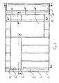
- the Fig. 1 shows the embodiment of a Drywall partition according to the invention in a front view.
- Thenbautrennwand has a base body 2, on which a garment made of plasterboard is arranged, which consists of a first layer of clothing 4 and a second layer of clothing 6.
- the base body 2 has the arrangement of the gypsum board on intermediate elements, which are shaped in the manner of a hat profile.
- the lens is designed as fire protection glass pane 10 of fire resistance class G30 according to DIN 4102 and held in a frame 12.
- the arrangement of the fire glass pane 10 and the embodiments of the frame 12 are based on the Fig. 2 to Fig. 5 which explains the in Fig. 1 designated sections represent AA, BB, CC, DD.
- Fig. 2 shows the in Fig. 1 designated section AA.
- the second garment layer 6 has a recess 14 for the frame 12, which is essentially congruent with the recess 16 of the first garment layer 6, but smaller than the recess 16 of the first garment layer 4.
- the recesses are only once with the reference numerals 14, 16 in Fig. 2 Mistake.
- thenbautrennwand on a contact surface on which the fire glass pane 10 is supported see FIG. 1 the contact surface provided only once by the reference numeral 18.
- a thermally resistant seal On the fire protection glass pane 10 is a thermally resistant seal, which is arranged in the manner of a sealing strip 20 respectively on the front side 22 and the back 24 of the fire protection glass pane 10.
- the sealing tape 20 on the fire protection glass pane 10th Disc surfaces
- a first sealing and spring action on the outer edge of the disc surface of the fire glass pane 10 and a second sealing and spring action at a distance to the first sealing and spring action of the fire glass pane 10 in the circumferential direction fire glass pane 10 are realized circumferentially.
- the sealing strip 20 is already mounted on the fire protection glass pane 10 before the on-site assembly of drywall dividing wall, so that the installation can be done easily and quickly on site.
- the frame 12 has a holding body 26, which is shaped in the manner of a hat profile and at least partially covers the disk surface and the end face of the fire-resistant glass pane 10.
- the hat profile is symmetrical and shaped so that it covers the sealing strip 20 to produce the first sealing effect completely and the sealing strip 20 to achieve the second sealing effect at least partially.
- the recess 16 of the first garment layer 4 is designed so that the hat profile between the end face of the fire protection glass pane 10 and the recess 16 belonging to the front side of the first garment layer 4 is arranged.
- the hat profile is screwed by means of a self-tapping screw 28 on the second garment layer 6 on the intermediate element 8 of the base body 2.
- the U-profile of the intermediate element 8 has two legs 30 of equal length, which are arranged substantially parallel to one another and are held spaced from one another by a flange 32 which is arranged substantially orthogonally to the legs 30.
- the garment layers 4, 6 with the fire-resistant glass pane held in the frame 12 can each be attached to the legs 30 10 are arranged.
- a spacer 34 is disposed in the direction of the weight between the lower end face of the fire protection glass pane 10 and the associated hat profile of the holding body 26, which consists of a thermally resistant plastic. As a result, damage or deformations are prevented by acting on the holding body 26 weight force of the fire glass pane 10.
- the holding body 26 has a closure element 36, which consists essentially of a thermally resistant plastic and is attached via a snap connection in the hat profile.
- the closure element 36 is designed so that it completely covers the sealing strip 20 for the first sealing effect and the sealing strip 20 for the second sealing effect on the front side 22 of the fire glass pane 10 and exerts a contact pressure on the sealing strip 20 to produce the second sealing effect.
- the end member 36 is symmetrically shaped so that it extends substantially equally long on the disc surface of the fire glass pane 10 and the surface of the first garment layer 4. Thereby, it covers on the surface of the first garment layer 4 from a thermally resistant and elastic seal 38, which is applied to the first garment layer 4.
- an intermediate element 8 ' is used, which is designed in the manner of a UW-profile.
- a fire protection glass pane 10 adjoins another fire protection glass pane 10.
- the two fire-resistant glass panes 10 are held on the base body 2 via a common holding body 26 by means of a self-tapping screw 28 via the second clothing layer 6.
- the common holding body 26 in turn covers with its closure element 36 arranged on the adjacent fire protection glass panes 10 sealing strips 20th
- the base body 2 has, in the region of the screw connection of the common holding body 26, an at least partial overlap of the legs 30 of the intermediate element 8 with the legs 30 'of the intermediate element 8'.
- the intermediate element 8 is designed as a U-profile and the intermediate element 8 'as a UW profile.
- the connection to a wall as it may be, for example, a masonry, at least on one end side of the drywall dividing wall via an intermediate element 8 ', which is also designed as a UW-profile.
- Fig. 4 shows the in Fig. 1 designated section CC.
- the structural design follows essentially the description or representation to / in Fig. 3 , Fig. 4 However, does not show a floor or wall connection element, since the illustrated section is not held directly on a wall, a floor or a ceiling of a room.
- Fig. 5 puts the in Fig. 1 designated section DD dar.
- a spacer 34 is arranged in the direction of the weight between the lower end face of the fire protection glass pane 10 and the associated hat profile of the holding body 26.
- a second embodiment of a drywall partition according to the invention is shown in a sectional view.
- the cutting process is similar to that in Fig. 1 designated section EE by a second example of aurebautrennwand- invention Fig. 6
- the holding body 26 are designed as U-profiles and have legs 42, 44, which have different lengths.
- the U-profile is in each case arranged on the first clothing layer 4 such that the longer leg 42 is supported directly on the first clothing layer 4 and is arranged parallel thereto. Between the legs 42, 44, the fire protection glass pane 10 is arranged.
- the longer leg 42 is designed to achieve a higher optical value such that it covers the first garment layer 4 in the region of its recess at least in sections.
- the sealing strip 20 is designed as already described with reference to the previous figures and arranged in this embodiment in each case on both disc surfaces of the fire protection glass pane 10 between the latter and the legs 42, 44.
- the sealing strip 20 is arranged such that a first sealing effect at the outer edge of the fire protection glass pane 10 and spaced a second sealing effect on the outer edge of the respective leg 42, 44 is achieved.
- a spacer 34 is arranged between the holding body 26 arranged at the bottom and the fire-resistant glass pane 10.
- the arrangement of the holding body 26, the fire protection glass pane 10, the first garment layer 4 and the spacer 34 to each other in this embodiment is the same for both fire protection glass panes 10.
- the floor and ceiling connection of the drywall dividing wall via elastically resilient means which is formed in this example by a rock wool layer 46.
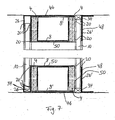
- Fig. 7 shows a third embodiment of an in Fig. 6 illustratedrapbautrennwand invention.
- the holding body 26, 26 ' are shaped differently.
- the holding body 26 ' isL executed in this embodiment as an L-profile.
- Whose longer leg 48 is disposed parallel to the disc surface of the fire glass pane 10 and is supported on this.
- the longer leg 48 is designed such that it at least partially covers the first garment layer 4 and thus realizes a higher visual value of the drywall dividing wall.
- a profile body 50 in the form of a U-profile is provided, which is the end faces of the first garment layers 4 and the space between the first garment layers 4 in the direction of the Scheiben inhabitnormalen the fire glass 10 covers. In the area of the window reveal, an improvement of the optical value can be achieved.
- the U-profile can also be perforated.
Landscapes
- Engineering & Computer Science (AREA)
- Architecture (AREA)
- Civil Engineering (AREA)
- Structural Engineering (AREA)
- Physics & Mathematics (AREA)
- Electromagnetism (AREA)
- Special Wing (AREA)
- Building Environments (AREA)
Applications Claiming Priority (2)
| Application Number | Priority Date | Filing Date | Title |
|---|---|---|---|
| DE200720008475 DE202007008475U1 (de) | 2007-06-13 | 2007-06-13 | Brandschutztrennwandsystem |
| DE200710027807 DE102007027807A1 (de) | 2007-06-13 | 2007-06-13 | Brandschutztrennwandsystem |
Publications (2)
| Publication Number | Publication Date |
|---|---|
| EP2003260A2 true EP2003260A2 (fr) | 2008-12-17 |
| EP2003260A3 EP2003260A3 (fr) | 2014-02-26 |
Family
ID=39708823
Family Applications (1)
| Application Number | Title | Priority Date | Filing Date |
|---|---|---|---|
| EP08010680.0A Withdrawn EP2003260A3 (fr) | 2007-06-13 | 2008-06-12 | Paroi de séparation en construction sèche |
Country Status (2)
| Country | Link |
|---|---|
| EP (1) | EP2003260A3 (fr) |
| DE (1) | DE202008018509U1 (fr) |
Cited By (3)
| Publication number | Priority date | Publication date | Assignee | Title |
|---|---|---|---|---|
| WO2015006862A1 (fr) * | 2013-07-19 | 2015-01-22 | Litezone Technologies Inc. | Unité de vitre à pression compensée |
| US10125537B2 (en) | 2014-07-18 | 2018-11-13 | Litezone Technologies Inc. | Pressure compensated glass unit |
| CN112627238A (zh) * | 2020-12-04 | 2021-04-09 | 青海天怡复合材料开发有限公司 | 一种玻璃纤维增强缠绕检查井及其生产工艺 |
Citations (3)
| Publication number | Priority date | Publication date | Assignee | Title |
|---|---|---|---|---|
| DE8437663U1 (de) | 1984-12-21 | 1985-05-09 | Akustikbau Lindner GmbH, 8382 Arnstorf | Mit einer Glasscheibe oder Glasscheiben versehenes Trennwandelement |
| DE29703401U1 (de) | 1997-02-26 | 1997-04-24 | Richter-System GmbH & Co KG, 64347 Griesheim | Brandschutzverglasung |
| DE29915102U1 (de) | 1999-08-28 | 2001-01-18 | Roehse, Thomas, 38350 Helmstedt | Systemtrennwand |
Family Cites Families (4)
| Publication number | Priority date | Publication date | Assignee | Title |
|---|---|---|---|---|
| DE9001398U1 (de) * | 1990-02-07 | 1990-05-31 | Lindner AG, 8382 Arnstorf | Trennwand mit Verglasungen |
| DE9211502U1 (de) * | 1992-08-26 | 1992-11-12 | Voest-Alpine Krems Finaltechnik Ges.M.B.H., Krems | Rahmen für die Verglasung von Fenstern |
| DE19544077C2 (de) * | 1995-11-25 | 1998-07-09 | Ohmen Gmbh | Gegen Hitzeeinwirkung widerstandsfähige Verglasung |
| EP0937857B1 (fr) * | 1998-02-24 | 2003-05-14 | Clestra Hauserman, S.A. | Cloison coupe-feu comportant des éléments vitrés |
-
2008
- 2008-06-12 DE DE200820018509 patent/DE202008018509U1/de not_active Expired - Lifetime
- 2008-06-12 EP EP08010680.0A patent/EP2003260A3/fr not_active Withdrawn
Patent Citations (3)
| Publication number | Priority date | Publication date | Assignee | Title |
|---|---|---|---|---|
| DE8437663U1 (de) | 1984-12-21 | 1985-05-09 | Akustikbau Lindner GmbH, 8382 Arnstorf | Mit einer Glasscheibe oder Glasscheiben versehenes Trennwandelement |
| DE29703401U1 (de) | 1997-02-26 | 1997-04-24 | Richter-System GmbH & Co KG, 64347 Griesheim | Brandschutzverglasung |
| DE29915102U1 (de) | 1999-08-28 | 2001-01-18 | Roehse, Thomas, 38350 Helmstedt | Systemtrennwand |
Cited By (6)
| Publication number | Priority date | Publication date | Assignee | Title |
|---|---|---|---|---|
| WO2015006862A1 (fr) * | 2013-07-19 | 2015-01-22 | Litezone Technologies Inc. | Unité de vitre à pression compensée |
| CN105531436A (zh) * | 2013-07-19 | 2016-04-27 | 利特佐内技术股份有限公司 | 压力补偿玻璃单元 |
| US9822581B2 (en) | 2013-07-19 | 2017-11-21 | Litezone Technologies Inc. | Pressure compensated glass unit |
| EA031195B1 (ru) * | 2013-07-19 | 2018-11-30 | Лайтзоун Текнолоджиз Инк. | Стеклопакет с компенсированным давлением |
| US10125537B2 (en) | 2014-07-18 | 2018-11-13 | Litezone Technologies Inc. | Pressure compensated glass unit |
| CN112627238A (zh) * | 2020-12-04 | 2021-04-09 | 青海天怡复合材料开发有限公司 | 一种玻璃纤维增强缠绕检查井及其生产工艺 |
Also Published As
| Publication number | Publication date |
|---|---|
| DE202008018509U1 (de) | 2014-10-02 |
| EP2003260A3 (fr) | 2014-02-26 |
Similar Documents
| Publication | Publication Date | Title |
|---|---|---|
| EP0086976A1 (fr) | Elément pour la protection contre le feu | |
| DE202009002800U1 (de) | Brandschutzverglasung | |
| EP1194673B1 (fr) | Element plat de protection contre le feu dote d'au moins deux panneaux de verre transparents coupe-feu | |
| EP3060725B1 (fr) | Composite anti-effraction et structure de mur porteur, de toit ou de plafond | |
| DE9101452U1 (de) | Brandschutzverglasung | |
| EP2003260A2 (fr) | Paroi de séparation en construction sèche | |
| EP3077602B1 (fr) | Construction de paroi présentant un vitrage composite et procédé pour la fabrication d'une construction de paroi présentant un vitrage composite | |
| EP1008697B1 (fr) | Elément d'isolation thermique et/ou phonique | |
| EP2405093A2 (fr) | Verrière ignifuge modulaire | |
| EP3412842B1 (fr) | Profilé de remplissage de joint | |
| DE4036735A1 (de) | Deckenelement | |
| EP1944429A1 (fr) | Porte de visite | |
| DE102007027807A1 (de) | Brandschutztrennwandsystem | |
| EP2365181B1 (fr) | Vitrage ignifuge horizontal | |
| DE202007002712U1 (de) | Isoliertüre mit Brandschutzeigenschaften für Kühlräume oder Tiefkühlräume | |
| DE202015102741U1 (de) | Scheibenverbundfenster | |
| DE69814585T2 (de) | Feuerbeständige Trennwand mit Verglasungselementen | |
| DE102013113760A1 (de) | Innenwandabdeckung zur Anwendung an einer Außenwand einer Gebäudekonstruktion | |
| DE9106478U1 (de) | Brandschutzverglasung | |
| DE102012103471A1 (de) | Brandschutzverglasung mit ungefüllter Silikonfuge | |
| EP2572055A1 (fr) | Paroi anti-effraction | |
| EP2845982B1 (fr) | Poteau pour une porte pivotante et vitrage ignifuge doté d'un tel poteau | |
| DE202007008475U1 (de) | Brandschutztrennwandsystem | |
| DE202023104429U1 (de) | Brandabschottung für Leitungen in Gebäuden | |
| EP4293168A1 (fr) | Cloison sèche, ainsi que procédé de fabrication d'une cloison sèche |
Legal Events
| Date | Code | Title | Description |
|---|---|---|---|
| PUAI | Public reference made under article 153(3) epc to a published international application that has entered the european phase |
Free format text: ORIGINAL CODE: 0009012 |
|
| AK | Designated contracting states |
Kind code of ref document: A2 Designated state(s): AT BE BG CH CY CZ DE DK EE ES FI FR GB GR HR HU IE IS IT LI LT LU LV MC MT NL NO PL PT RO SE SI SK TR |
|
| AX | Request for extension of the european patent |
Extension state: AL BA MK RS |
|
| RAP1 | Party data changed (applicant data changed or rights of an application transferred) |
Owner name: ROEHSE-HOLDING-GMBH |
|
| RIN1 | Information on inventor provided before grant (corrected) |
Inventor name: ROEHSE, THOMAS |
|
| PUAL | Search report despatched |
Free format text: ORIGINAL CODE: 0009013 |
|
| AK | Designated contracting states |
Kind code of ref document: A3 Designated state(s): AT BE BG CH CY CZ DE DK EE ES FI FR GB GR HR HU IE IS IT LI LT LU LV MC MT NL NO PL PT RO SE SI SK TR |
|
| AX | Request for extension of the european patent |
Extension state: AL BA MK RS |
|
| RIC1 | Information provided on ipc code assigned before grant |
Ipc: E04B 2/74 20060101AFI20140121BHEP Ipc: E06B 5/16 20060101ALI20140121BHEP Ipc: E06B 1/36 20060101ALI20140121BHEP Ipc: E06B 3/24 20060101ALI20140121BHEP |
|
| AKY | No designation fees paid | ||
| REG | Reference to a national code |
Ref country code: DE Ref legal event code: R108 |
|
| REG | Reference to a national code |
Ref country code: DE Ref legal event code: R108 Effective date: 20141029 |
|
| STAA | Information on the status of an ep patent application or granted ep patent |
Free format text: STATUS: THE APPLICATION IS DEEMED TO BE WITHDRAWN |
|
| 18D | Application deemed to be withdrawn |
Effective date: 20140827 |