EP2002176B1 - Optoelectronic headlight - Google Patents
Optoelectronic headlight Download PDFInfo
- Publication number
- EP2002176B1 EP2002176B1 EP07722079.6A EP07722079A EP2002176B1 EP 2002176 B1 EP2002176 B1 EP 2002176B1 EP 07722079 A EP07722079 A EP 07722079A EP 2002176 B1 EP2002176 B1 EP 2002176B1
- Authority
- EP
- European Patent Office
- Prior art keywords
- emission regions
- emission
- conductor track
- carrier body
- headlamp according
- Prior art date
- Legal status (The legal status is an assumption and is not a legal conclusion. Google has not performed a legal analysis and makes no representation as to the accuracy of the status listed.)
- Ceased
Links
Images


Classifications
-
- F—MECHANICAL ENGINEERING; LIGHTING; HEATING; WEAPONS; BLASTING
- F21—LIGHTING
- F21S—NON-PORTABLE LIGHTING DEVICES; SYSTEMS THEREOF; VEHICLE LIGHTING DEVICES SPECIALLY ADAPTED FOR VEHICLE EXTERIORS
- F21S41/00—Illuminating devices specially adapted for vehicle exteriors, e.g. headlamps
- F21S41/60—Illuminating devices specially adapted for vehicle exteriors, e.g. headlamps characterised by a variable light distribution
- F21S41/65—Illuminating devices specially adapted for vehicle exteriors, e.g. headlamps characterised by a variable light distribution by acting on light sources
-
- H—ELECTRICITY
- H10—SEMICONDUCTOR DEVICES; ELECTRIC SOLID-STATE DEVICES NOT OTHERWISE PROVIDED FOR
- H10H—INORGANIC LIGHT-EMITTING SEMICONDUCTOR DEVICES HAVING POTENTIAL BARRIERS
- H10H29/00—Integrated devices, or assemblies of multiple devices, comprising at least one light-emitting semiconductor element covered by group H10H20/00
- H10H29/10—Integrated devices comprising at least one light-emitting semiconductor component covered by group H10H20/00
-
- F—MECHANICAL ENGINEERING; LIGHTING; HEATING; WEAPONS; BLASTING
- F21—LIGHTING
- F21S—NON-PORTABLE LIGHTING DEVICES; SYSTEMS THEREOF; VEHICLE LIGHTING DEVICES SPECIALLY ADAPTED FOR VEHICLE EXTERIORS
- F21S41/00—Illuminating devices specially adapted for vehicle exteriors, e.g. headlamps
- F21S41/60—Illuminating devices specially adapted for vehicle exteriors, e.g. headlamps characterised by a variable light distribution
- F21S41/65—Illuminating devices specially adapted for vehicle exteriors, e.g. headlamps characterised by a variable light distribution by acting on light sources
- F21S41/663—Illuminating devices specially adapted for vehicle exteriors, e.g. headlamps characterised by a variable light distribution by acting on light sources by switching light sources
-
- H—ELECTRICITY
- H10—SEMICONDUCTOR DEVICES; ELECTRIC SOLID-STATE DEVICES NOT OTHERWISE PROVIDED FOR
- H10H—INORGANIC LIGHT-EMITTING SEMICONDUCTOR DEVICES HAVING POTENTIAL BARRIERS
- H10H20/00—Individual inorganic light-emitting semiconductor devices having potential barriers, e.g. light-emitting diodes [LED]
- H10H20/80—Constructional details
- H10H20/81—Bodies
- H10H20/819—Bodies characterised by their shape, e.g. curved or truncated substrates
-
- H—ELECTRICITY
- H10—SEMICONDUCTOR DEVICES; ELECTRIC SOLID-STATE DEVICES NOT OTHERWISE PROVIDED FOR
- H10H—INORGANIC LIGHT-EMITTING SEMICONDUCTOR DEVICES HAVING POTENTIAL BARRIERS
- H10H20/00—Individual inorganic light-emitting semiconductor devices having potential barriers, e.g. light-emitting diodes [LED]
- H10H20/80—Constructional details
- H10H20/84—Coatings, e.g. passivation layers or antireflective coatings
-
- F—MECHANICAL ENGINEERING; LIGHTING; HEATING; WEAPONS; BLASTING
- F21—LIGHTING
- F21S—NON-PORTABLE LIGHTING DEVICES; SYSTEMS THEREOF; VEHICLE LIGHTING DEVICES SPECIALLY ADAPTED FOR VEHICLE EXTERIORS
- F21S41/00—Illuminating devices specially adapted for vehicle exteriors, e.g. headlamps
-
- F—MECHANICAL ENGINEERING; LIGHTING; HEATING; WEAPONS; BLASTING
- F21—LIGHTING
- F21S—NON-PORTABLE LIGHTING DEVICES; SYSTEMS THEREOF; VEHICLE LIGHTING DEVICES SPECIALLY ADAPTED FOR VEHICLE EXTERIORS
- F21S41/00—Illuminating devices specially adapted for vehicle exteriors, e.g. headlamps
- F21S41/10—Illuminating devices specially adapted for vehicle exteriors, e.g. headlamps characterised by the light source
- F21S41/14—Illuminating devices specially adapted for vehicle exteriors, e.g. headlamps characterised by the light source characterised by the type of light source
- F21S41/141—Light emitting diodes [LED]
-
- F—MECHANICAL ENGINEERING; LIGHTING; HEATING; WEAPONS; BLASTING
- F21—LIGHTING
- F21W—INDEXING SCHEME ASSOCIATED WITH SUBCLASSES F21K, F21L, F21S and F21V, RELATING TO USES OR APPLICATIONS OF LIGHTING DEVICES OR SYSTEMS
- F21W2102/00—Exterior vehicle lighting devices for illuminating purposes
-
- F—MECHANICAL ENGINEERING; LIGHTING; HEATING; WEAPONS; BLASTING
- F21—LIGHTING
- F21Y—INDEXING SCHEME ASSOCIATED WITH SUBCLASSES F21K, F21L, F21S and F21V, RELATING TO THE FORM OR THE KIND OF THE LIGHT SOURCES OR OF THE COLOUR OF THE LIGHT EMITTED
- F21Y2105/00—Planar light sources
- F21Y2105/10—Planar light sources comprising a two-dimensional [2D] array of point-like light-generating elements
-
- F—MECHANICAL ENGINEERING; LIGHTING; HEATING; WEAPONS; BLASTING
- F21—LIGHTING
- F21Y—INDEXING SCHEME ASSOCIATED WITH SUBCLASSES F21K, F21L, F21S and F21V, RELATING TO THE FORM OR THE KIND OF THE LIGHT SOURCES OR OF THE COLOUR OF THE LIGHT EMITTED
- F21Y2115/00—Light-generating elements of semiconductor light sources
- F21Y2115/10—Light-emitting diodes [LED]
-
- H—ELECTRICITY
- H10—SEMICONDUCTOR DEVICES; ELECTRIC SOLID-STATE DEVICES NOT OTHERWISE PROVIDED FOR
- H10H—INORGANIC LIGHT-EMITTING SEMICONDUCTOR DEVICES HAVING POTENTIAL BARRIERS
- H10H20/00—Individual inorganic light-emitting semiconductor devices having potential barriers, e.g. light-emitting diodes [LED]
- H10H20/01—Manufacture or treatment
- H10H20/034—Manufacture or treatment of coatings
-
- H—ELECTRICITY
- H10—SEMICONDUCTOR DEVICES; ELECTRIC SOLID-STATE DEVICES NOT OTHERWISE PROVIDED FOR
- H10H—INORGANIC LIGHT-EMITTING SEMICONDUCTOR DEVICES HAVING POTENTIAL BARRIERS
- H10H20/00—Individual inorganic light-emitting semiconductor devices having potential barriers, e.g. light-emitting diodes [LED]
- H10H20/01—Manufacture or treatment
- H10H20/036—Manufacture or treatment of packages
- H10H20/0364—Manufacture or treatment of packages of interconnections
-
- H—ELECTRICITY
- H10—SEMICONDUCTOR DEVICES; ELECTRIC SOLID-STATE DEVICES NOT OTHERWISE PROVIDED FOR
- H10H—INORGANIC LIGHT-EMITTING SEMICONDUCTOR DEVICES HAVING POTENTIAL BARRIERS
- H10H20/00—Individual inorganic light-emitting semiconductor devices having potential barriers, e.g. light-emitting diodes [LED]
- H10H20/80—Constructional details
- H10H20/85—Packages
- H10H20/851—Wavelength conversion means
-
- H—ELECTRICITY
- H10—SEMICONDUCTOR DEVICES; ELECTRIC SOLID-STATE DEVICES NOT OTHERWISE PROVIDED FOR
- H10H—INORGANIC LIGHT-EMITTING SEMICONDUCTOR DEVICES HAVING POTENTIAL BARRIERS
- H10H20/00—Individual inorganic light-emitting semiconductor devices having potential barriers, e.g. light-emitting diodes [LED]
- H10H20/80—Constructional details
- H10H20/85—Packages
- H10H20/857—Interconnections, e.g. lead-frames, bond wires or solder balls
-
- H—ELECTRICITY
- H10—SEMICONDUCTOR DEVICES; ELECTRIC SOLID-STATE DEVICES NOT OTHERWISE PROVIDED FOR
- H10W—GENERIC PACKAGES, INTERCONNECTIONS, CONNECTORS OR OTHER CONSTRUCTIONAL DETAILS OF DEVICES COVERED BY CLASS H10
- H10W70/00—Package substrates; Interposers; Redistribution layers [RDL]
- H10W70/01—Manufacture or treatment
- H10W70/05—Manufacture or treatment of insulating or insulated package substrates, or of interposers, or of redistribution layers
- H10W70/093—Connecting or disconnecting other interconnections thereto or therefrom, e.g. connecting bond wires or bumps
-
- H—ELECTRICITY
- H10—SEMICONDUCTOR DEVICES; ELECTRIC SOLID-STATE DEVICES NOT OTHERWISE PROVIDED FOR
- H10W—GENERIC PACKAGES, INTERCONNECTIONS, CONNECTORS OR OTHER CONSTRUCTIONAL DETAILS OF DEVICES COVERED BY CLASS H10
- H10W70/00—Package substrates; Interposers; Redistribution layers [RDL]
- H10W70/60—Insulating or insulated package substrates; Interposers; Redistribution layers
-
- H—ELECTRICITY
- H10—SEMICONDUCTOR DEVICES; ELECTRIC SOLID-STATE DEVICES NOT OTHERWISE PROVIDED FOR
- H10W—GENERIC PACKAGES, INTERCONNECTIONS, CONNECTORS OR OTHER CONSTRUCTIONAL DETAILS OF DEVICES COVERED BY CLASS H10
- H10W90/00—Package configurations
-
- H—ELECTRICITY
- H10—SEMICONDUCTOR DEVICES; ELECTRIC SOLID-STATE DEVICES NOT OTHERWISE PROVIDED FOR
- H10W—GENERIC PACKAGES, INTERCONNECTIONS, CONNECTORS OR OTHER CONSTRUCTIONAL DETAILS OF DEVICES COVERED BY CLASS H10
- H10W90/00—Package configurations
- H10W90/10—Configurations of laterally-adjacent chips
Definitions
- the invention relates to an optoelectronic headlight with at least one luminescence diode chip that emits electromagnetic radiation.
- the invention is defined by claim 1.
- An optoelectronic headlight is, for example, in the WO 2004/088200 A2 described. This has a plurality of headlight elements, each of which has at least one luminescence diode chip, a primary optics element assigned to the luminescence diode chip and a headlight element output.
- the headlight element outputs are arranged in at least two groups such that their arrangement corresponds to a desired radiation characteristic of the headlight. The two groups of headlight elements can be operated independently of one another.
- An optoelectronic headlight is also in the EP 1 515 368 A2 described. Another optoelectronic headlight is in the EP 1 526 581 A2 described.
- a headlight of the type mentioned at the outset which has a luminescence diode chip with at least two spatial emission regions. At least partial areas of the emission areas are lateral spaced from one another, ie the emission regions do not overlap laterally.
- the emission regions are shaped differently in a plan view of a main extension plane assigned to them, are of different sizes and / or are not rectangular in shape and are oriented differently.
- the emission ranges can be controlled independently of one another.
- the luminescence diode chip is arranged on a carrier body and, together with the carrier body, is covered with an electrical insulating layer on which an electrical conductor track structure is formed, the emission regions each having at least one electrical connection surface which is connected to the conductor track structure.
- the headlight has an optical element for forming a beam cone.
- the headlight is a front headlight for motor vehicles.
- a lighting unit for projection applications for example for a video projector, is disclosed.
- headlight functions can be advantageously implemented with the headlight.
- these are, for example, motorway lights, city lights, country road lights and cornering lights, which can be implemented by correspondingly switching and controlling the emission areas.
- a headlight cone means an arbitrarily shaped volume that is illuminated by the headlight light, excluding areas in which the brightness is more than an order of magnitude lower than the maximum brightness at the same distance from the headlight.
- the radiation characteristic is to be understood as one or more properties of the headlight cone, such as light intensity in different solid angles, light / dark transitions or a cross-sectional shape.
- cross-sectional shape is meant the shape of a cross-section of the headlight cone in a plane perpendicular to a main emission direction of the headlight.
- the shape of at least one of the emission areas in a plan view of the main extension plane is according to one advantageous embodiment is not rectangular.
- the emission region has, in particular, boundaries running along lines that are oriented obliquely to one another.
- the shape of at least one of the emission regions has a corner with an acute angle or with an obtuse angle in a plan view of the main extension plane. Additionally or alternatively, the shape of at least one of the emission regions has a kink with an obtuse angle in a plan view of the main extension plane.
- a "kink” does not necessarily mean a sharp corner. Rather, the kink can also be rounded, for example.
- the shape of at least one of the emission regions preferably does not have an axis of symmetry in a plan view of the main extension plane.
- adjacent emission regions are at a relatively small distance from one another in the lateral direction.
- the distance is advantageously less than or equal to 100 ⁇ m, preferably less than or equal to 50 ⁇ m, particularly preferably less than or equal to 20 ⁇ m. With such a small distance, headlight cones with a particularly homogeneous light density distribution can be realized.
- the luminescent diode chip is arranged on a carrier body and covered with an electrical insulating layer together with the carrier body.
- An electrical conductor track structure is formed on the insulating layer, the emission regions each having at least one electrical connection surface which is connected to the conductor track structure.
- the electrical connection surfaces are in particular electrically conductively connected to the conductor track structure.
- the connection areas are preferably also mechanically connected to the conductor track structure.
- the conductor track structure can in principle be constructed and structured as desired, in individual cases it can in particular also consist of an unstructured electrically conductive layer.
- the conductor track structure preferably comprises a plurality of conductor tracks, which can be both connected to one another or additionally or alternatively electrically isolated from one another.
- a conductor track structure designed in this way for electrically contacting and interconnecting the luminescence diode chip or the luminescence diode chips is particularly advantageous for headlight applications.
- the headlamp not only enables various radiation characteristics to be implemented precisely, it can also be installed and connected in a cost-effective, electrically conductive manner and provided with an optical element that can be brought very close to the emission areas.
- Optical elements can in particular be brought closer to the emission regions than is the case when the luminescence diode chip or is electrically contacted the LED chips would be possible using one or more bond wires.
- the headlight has at least one optical element.
- Each luminescence diode chip is preferably assigned at least one optical element, particularly preferably several or all emission regions are assigned to one optical element.
- the optical element is used to form a radiation cone with the highest possible radiation intensity and the lowest possible divergence.
- An optical element is preferably assigned to several luminescence diode chips. This has the advantage of simplified assembly, for example, compared to the case where each luminescence diode chip is assigned its own optical element.
- a light input of the optical element is positioned as close as possible to a luminescence diode chip, which is advantageously possible particularly well with the specified wireless contacting, since these are formed with a particularly low height compared to contacting by means of a bonding wire can.
- the solid angle at which the light is emitted from the optical element is expediently reduced by means of the optical element as close as possible to the luminescence diode chip, where a cross-sectional area of the radiation cone is still small. This is particularly necessary if the highest possible radiation intensity is to be projected onto the smallest possible area, as is the case with headlight applications or projection devices.
- an electronic component in addition to the luminescence diode chip, is arranged on the carrier body and has at least one electrical connection surface which is connected in an electrically conductive manner via the conductor track structure.
- the connection area of the component is preferably electrically conductively connected to at least one connection area of the emission regions via the conductor track structure.
- the electrical component is different from the LED chip. Different means that the components differ in functional and / or structural features, in particular they serve different purposes, their mode of operation is based on different physical effects, they have differently shaped electrical connection surfaces or they can be assembled in different ways.
- the electronic component is a passive component and / or an integrated circuit. It is preferably suitable for SMD mounting (surface mountable device mounting). Additionally or alternatively, the component is suitable for assembly that involves the use of bond wires. Components of this type can advantageously be connected in an electrically conductive manner in the headlight instead of at least partially by means of solder or by means of bonding wires on the basis of the conductor track structure.
- the electrical connection area of at least one emission region is advantageously connected in an electrically conductive manner to a connection region of the carrier body via the conductor track structure.
- the insulating layer particularly advantageously has a luminescence conversion material.
- the luminescence conversion material can be used to convert electromagnetic radiation to be emitted by the component from a first wavelength range into electromagnetic radiation from a second wavelength range. For example, blue radiation can be partially converted into yellow radiation in this way. With a suitable intensity ratio of blue and yellow radiation, white light can be generated in this way. In the case of such a luminescence conversion, it is particularly advantageous in terms of efficiency if the insulating layer is directly adjacent to the surface of the emission regions provided for coupling out the radiation.
- the luminescence diode chip or the luminescence diode chips are mounted on a chip carrier which is applied to the carrier body.
- a chip carrier By using a separate chip carrier, particularly good heat dissipation from the luminescence diode chip can be achieved, for example, with a suitable selection of materials.
- the chip carrier can also be a housing body of a luminescence diode component, a complete electrical mounting of the luminescence diode chip on the chip housing advantageously not being necessary. Rather, the luminescence diode chips can only be connected in an electrically conductive manner by means of the conductor track structure after the chip carrier has been applied to the carrier body.
- a method for producing an optoelectronic headlight that emits electromagnetic radiation is specified.
- a carrier body and at least one luminescence diode chip are provided, the luminescence diode chip having at least two emission regions which, in a plan view of a main extension plane assigned to them, have different shapes, different sizes and / or different orientations in the same form.
- Each of the emission areas has at least one electrical connection area. According to the invention, the emission areas can be controlled independently of one another.
- the LED chip is applied to the carrier body.
- An insulating layer is subsequently applied to the luminescence diode chip and the carrier body.
- recesses are formed in the insulating layer in order to expose at least one electrical connection surface of the emission regions.
- Electrically conductive material is applied to the insulating layer in such a way that it is connected to the electrical connection areas in order to form an electrical conductor track structure.
- the electrically conductive material is expediently applied in the form of a layer.
- this layer can expediently be structured below, so that conductor tracks of the conductor track structure which are electrically insulated from one another can also be produced.
- a further method for producing an optoelectronic headlight emitting electromagnetic radiation is specified, in which at least two luminescence diode chips are provided in addition to a carrier body.
- the luminescence diode chips each have at least one emission region with at least one electrical connection area.
- the emission regions are shaped differently, differently in size and / or not rectangularly shaped and oriented differently.
- Further method steps include applying the luminescent diode chip to the carrier body, applying an insulating layer to the luminescent diode chip and the carrier body, forming recesses in the insulating layer to expose at least one electrical connection area of the emission regions, and applying electrically conductive material to the insulating layer , in such a way that it is connected to the electrical connection pads, to form an electrical conductor track structure.
- the conductor track structure can be designed as described above.
- At least one electrical component is provided and before the application of the insulating layer applied to the carrier body.
- the insulating layer is applied in such a way that the electrical component is also partially or completely covered.
- Further method steps of this embodiment include forming recesses in the insulating layer to expose the electrical connection area of the component, and applying electrically conductive material to the insulating layer to form an electrical conductor track structure such that the electrically conductive material is connected to the electrical connection area of the component becomes.
- the application of the insulating layer, the formation of recesses and the application of electrically conductive material can be carried out in a number of batch processes.
- these batch processes a large number of optoelectronic headlights can be processed in parallel, which is a cost-effective alternative to the use of individual processes, as are required, for example, when bonding using bonding wires.
- the investment required for the necessary operating systems can also be kept low.
- the batch processes can be set up flexibly for different products. It is basically possible to manufacture different products on one production line. This can be done one after the other, after changing the different process parameters, or in parallel.
- the method can be used in particular for the electrically conductive contacting and connecting of components of different component classes.
- the application of the insulating layer advantageously includes the application of a prefabricated layer. Additionally or alternatively, the application of the insulating layer advantageously comprises printing, spraying or spinning on a material for the insulating layer. These measures make it possible to apply the insulating layer in a technically simple and inexpensive manner.
- a precursor layer is first applied to the luminescence diode chip and the carrier body in order to apply the insulating layer. This is done, for example, by means of a sol-gel process, by vapor deposition or by spin coating a suspension.
- a first temperature treatment is carried out which is suitable for removing organic constituents from the precursor layer.
- the material is subsequently subjected to a second temperature treatment which is suitable for compacting the precursor layer. This process can be used to produce a thin and uniform layer of glass.
- the recesses in the insulating layer are preferably produced by a method step which comprises laser processing.
- the insulating layer is removed in the areas of the recesses to be produced using laser radiation. With laser processing, the size, shape and depth of the recesses can be set precisely and generated immediately.
- the application of electrically conductive material advantageously comprises the application of a metal layer by means of a PVD method and a reinforcement of the metal layer by means of electrodeposition.
- a suitable PVD process is sputtering, for example.
- the electrically conductive material can also be applied using a printing process, in particular a screen printing process.
- the electrically conductive material can also be produced using a spraying process or a spin coating process.
- a luminescent diode chip which emits electromagnetic radiation.
- the luminescence diode chip has at least two emission regions which can be controlled independently of one another and which, in a plan view of a main extension plane assigned to them, have different shapes, different sizes and / or different orientations in the same form.
- the luminescence diode chip is particularly suitable for use in the optoelectronic headlight.
- the shape of at least one of the emission areas in a plan view of the main extension plane is not rectangular, has a corner with an acute or an obtuse angle, has a kink with an obtuse angle and / or no axis of symmetry having.
- Luminescence diode chip shown has a first emission region 21, a second emission region 22 and a third emission region 23.
- the emission regions are arranged on a common carrier substrate 24.
- the first emission region 21 and the second emission region 23 have a pentagonal shape in the plan view shown on their main extension plane.
- the pentagonal shape of the first emission region 21 has three right angles and two obtuse angles ⁇ , ⁇ .
- the third emission region 23 also comprises three right angles. In addition, however, it has an obtuse angle ⁇ and an acute angle ⁇ .
- An "angle of a shape of the emission region” means an angle in which two adjacent partial straight lines of the contour of the shape are in relation to one another, the angle being measured inside the shape, as in Figure 1 shown.
- the obtuse angle ⁇ is, for example, between 185 ° and 205 ° inclusive.
- the obtuse angle ⁇ is preferably approximately 195 °.
- the second emission region 22 has a square shape with two right angles, an acute angle and an obtuse angle. It is arranged between the first emission region 21 and the third emission region 23.
- the three emission regions 21, 22, 23 result in an essentially rectangular, in particular a square shape.
- the emission areas can be put into operation independently of each other.
- FIG 4 is a schematic sectional view of one along the in Figure 1 shown dashed line running section.
- the emission regions 21, 23 are formed by luminescent diode layers 210, 230.
- the luminescence diode layers 210, 230 are, for example, semiconductor layer sequences with an active zone that is suitable to emit electromagnetic radiation when an electric current is applied.
- the luminescent diode layers are based, for example, on nitride compound semiconductor materials and are suitable for emitting electromagnetic radiation from the blue and / or ultraviolet spectrum.
- Nitride compound semiconductor materials are compound semiconductor materials which contain nitrogen, such as materials from the system In x Al y Ga 1-xy N with 0 x x 1 1, 0 y y 1 1 and x + y 1. 1.
- the luminescent diode layers have, for. B. at least one semiconductor layer made of a nitride compound semiconductor material.
- a conventional pn junction, a double heterostructure, a single quantum well structure (SQW structure) or a multiple quantum well structure (MQW structure) can be contained in the luminescent diode layers.
- SQW structure single quantum well structure
- MQW structure multiple quantum well structure
- the luminescence diode layers 210, 230 are applied to a substrate 24.
- This can be a growth substrate on which the luminescent diode layers have grown in the form of a semiconductor layer sequence.
- the substrate 24 can also be a carrier substrate on which the luminescent diode layers 210, 230 have been applied after they have been formed.
- a reflector can be arranged, for example, between the luminescence diode layers 210, 230 and the substrate 24, which reflects electromagnetic radiation that is generated in the luminescence diode layers 210, 230.
- This can be, for example, a metallic or dielectric mirror.
- the reflector preferably comprises a dielectric layer and a metallic layer applied to this dielectric layer, the dielectric layer adjoining the luminescence diode layers 210, 230 (not shown).
- the luminescent diode layers 210, 230 are spaced apart from one another. As a result, their emission regions 21, 23 can be controlled independently of one another. However, different emission ranges can be controlled independently of one another in any other way. It is also possible, for example, for the emission regions to partially overlap with one another along the main extension plane assigned to them, that is to say the emission regions need not be arranged in physically separate regions.
- Partially overlapping emission areas can be achieved, for example, by means of current barriers, by means of which an electrical current, which is impressed, for example, in a first emission area, is only partially prevented from flowing through areas of a luminescence diode layer which is assigned to a second emission area.
- the current barrier or the current barriers also provide a corresponding partial shielding of the electrical current when the second emission region is energized. In total, two different, However, some of the emission areas overlap with one another.
- the in Figure 2 Luminescence diode chip shown has a first emission region 21 and two second emission regions 22.
- the first emission region 21 has a triangular shape with a right angle and two acute angles ⁇ , ⁇ .
- the two second emission regions 22 have an elongated rectangular shape. They are arranged side by side in such a way that two of their long sides run parallel to one another and face one another.
- the first emission region 21 is arranged relative to the two second emission regions 22 such that the overall arrangement of the emission regions forms a pentagonal shape with an obtuse angle ⁇ .
- the obtuse angle ⁇ can, like the obtuse angle of the third emission region of the in Figure 1 luminescence diode chips shown to be obtained.
- the in Figure 3 The luminescence diode chip shown has five emission regions 21, 22 of the same shape.
- the shapes of three first emission areas 21 have a first orientation and the shapes of two second emission areas 22 have a second orientation, the first orientation being rotated parallel to the main extension plane of the emission areas by 180 ° with respect to the second orientation.
- the emission areas all have a triangular shape with a right angle and two acute angles.
- the overall arrangement of the emission areas again results in a pentagonal shape with an obtuse angle ⁇ , which is like that obtuse angle ⁇ described in the preceding examples can be obtained.
- Luminescent diode chips shown are well suited for use in a headlight module for motor vehicle headlights.
- an asymmetrical emission characteristic is prescribed in many countries, in which emitted headlight cones have an asymmetrical cross section with an obtuse angle.
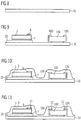
- the in Figure 5 The optoelectronic headlight shown has an optoelectronic component 50 and a passive component 100. These different types of electrical components are arranged on a carrier body 10. As in the sectional view of Figure 13 It can be seen that the components 50, 100 and the carrier body 10 are covered with an electrical insulating layer 3. An electrical conductor track structure 14 is formed on the insulating layer 3. The optoelectronic component 50 and the passive electrical component 100 have electrical connection surfaces 7, 6, 106 which are connected to the conductor track structure 14.
- the optoelectronic component 50 has a chip carrier 20 with an electrical connection area 7.
- a luminescence diode chip 1 is applied to part of the electrical connection surface 7.
- the latter On one side facing away from the electrical connection area 7 of the chip carrier 20, the latter has three emission regions 21, 22, 23, each with an electrical connection area 6. These electrical connection areas 6 and the part of the electrical connection area 7 not covered by the luminescence diode chip 1 form electrical connection surfaces of the optoelectronic component 50 in each case.
- the passive component 100 is, for example, a resistor, a varistor or a capacitor.
- One of its electrical connection surfaces 106 is electrically conductively connected to the electrical connection surface 6 of the third emission region 23 of the luminescence diode chip 1 via an electrical conductor track of the conductor track structure 14.
- the second electrical connection surface 106 is likewise connected in an electrically conductive manner to a conductor track of the conductor track structure 14, but this conductor track does not lead directly to a connection surface of the optoelectronic component 50, but away from it.
- the in Figure 5 The headlamp shown can be manufactured, for example, with a carrier body 10 that has no electrical conductor tracks or electrical connection surfaces. All electrical conductor tracks of the headlamp are advantageously formed, for example, as part of the conductor track structure 14 on the insulating layer 3.
- the in Figure 6 The headlight shown has a carrier body 10 with an electrical connection surface 7, on which a first luminescence diode chip 1 and a second luminescence diode chip 2 are applied.
- the first luminescence diode chip 1 has a single emission area with a rectangular shape in plan view of its main extension plane.
- the second luminescence diode chip 2 has a single emission region with a triangular shape in a plan view of its main extension plane.
- the distance between the LED chips is, for example, about 20 ⁇ m.
- the side of the luminescence diode chips 1, 2 facing the electrical connection surface 7 are electrically conductively connected to the connection surface 7.
- the sides of the luminescence diode chips 1, 2 facing away from the electrical connection area 7 each have an electrical connection area 6, which is electrically conductively connected to a conductor track of the conductor track structure 14.
- the connection area 6 of the first luminescence diode chip 1 is electrically conductively connected to an electrical connection area 8 of the carrier body 10 via the conductor track structure.
- a further conductor track of the conductor track structure 14 connects the electrical connection area 7 to a connection area 106 of a passive component 100, which is also located on the carrier body 10.
- This passive component 100 has two electrical connection areas 106, the second electrical connection area also being electrically connected to a conductor track of the conductor track structure 14 is conductively connected.
- the conductor track structure 14 it is possible for the conductor track structure 14 to have no conductor tracks that directly connect electrical connection surfaces of components of the headlamp to one another in an electrically conductive manner.
- Cutouts of a headlight shown can preferably use a plurality of luminescence diode chips. For example, between four and ten inclusive LED chips are included. Alternatively, the headlamp has, for example, between four and ten inclusive, including optoelectronic components, each of which contains at least one luminescence diode chip 1.
- the passive components serve, for example, to stabilize the electrical voltage applied to the optoelectronic components.
- varistors are expediently used.
- further electrical components which differ from the optoelectronic components 50, can be contained in the headlight for any purpose, such as, for example, to form suitable electrical control circuits.
- this also includes logic circuits which are formed using integrated circuits.
- logic chips and / or memory chips can be arranged on the carrier body 10 and connected to the conductor track structure 14 in an electrically conductive manner.
- FIG Figure 7 A section of an exemplary headlamp that has an integrated circuit 200 is shown in FIG Figure 7 shown.
- the integrated circuit 200 is, for example, provided with a housing and is suitable for being mounted and connected in a manner similar to an SMD component.
- integrated circuits without a housing (“bare dies") can also be used. Such bare this are usually mechanically mounted by means of gluing or soldering and electrically connected by a wire bonding process.
- integrated circuits can also be used, which are suitable for being connected via a bump assembly.
- such an integrated circuit 200 is applied to the carrier body 10 and connected in an electrically conductive manner using the conductor track structure 14 applied to an insulating layer 3.
- all electrical connection areas 206 of the integrated circuit 200 are directly electrically conductively connected to conductor tracks of the conductor track structure 14.
- a luminescence diode chip 1 with a first and a second non-rectangular emission region 21, 22 is applied to the carrier body 10.
- the first emission area 21 is triangular, the second emission area is square. They each have an electrical connection surface 6.
- Another Connection surface 7 for the electrical connection of the luminescence diode chip is arranged next to the chip on the carrier body 10.
- the electrical connections 6, 7 are electrically conductively connected to connection areas of the integrated circuit 200 via conductor tracks of the conductor track structure.
- the insulating layer is shown in the Figures 5 , 6 and 7 not shown. It is arranged between the conductor track structure 14 and the other elements shown in the figures, the insulating layer having recesses for plated-through holes in the regions of the connection surfaces to be contacted. This structure is illustrated by the following description of exemplary methods for producing a headlight with the inclusion of Figures 8 to 21 .
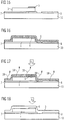
- FIGS 8 to 13 are schematic sectional views of various process stages of an exemplary method for producing the in Figure 5 headlights shown included.
- the sectional view shown is an illustration of a section along the line shown in FIG Figure 5 drawn dashed line.
- Section views shown are representations of a corresponding section during previous process stages of the exemplary process.
- the carrier body 10 has, for example, the shape of a flat plate.
- the support body can also have structures and unevenness exhibit.
- it contains a ceramic material, a plastic and / or a metal or essentially consists of one of these materials.
- the carrier body consists of aluminum nitride.
- At least two different types of electrical components 50, 100 are applied to the carrier body 10, see Figure 9 . These components are expediently fastened to the carrier body 10. Although an electrically conductive connection of the components to the carrier body 10 is not required, a connection with a high thermal conductivity between the components and the carrier body 10 can be advantageous.
- the components 50, 100 are connected to the carrier body 10, for example, by means of adhesive and / or by means of a solder. In principle, however, such a connection can also be dispensed with.
- One of the components is an optoelectronic component 50, which comprises a chip carrier 20, an electrical connection layer 7 applied on the chip carrier 20 and a luminescence diode chip 1 applied on the electrical connection layer 7.
- the luminescence diode chip 1 has on its outer surface facing the electrical connection layer 7 an electrical connection surface which is connected, for example by means of soldering, to the electrical connection layer 7 in an electrically conductive and mechanical manner (not shown).
- the luminescence diode chip 1 has an electrical connection area 6 on a side facing away from the electrical connection layer 7.
- the connection surface 6 is, for example, by a contact layer or a sequence of contact layers formed, which is applied to a luminescence diode layer of the luminescence diode chip 1 and is structured, for example, by means of photolithography.
- the chip carrier 20 has at least one of the materials ceramic, metal and plastic or consists of one of these materials.
- it is made of aluminum nitride.
- a passive component 100 is applied to the carrier body 10 at a distance from the optoelectronic component 50.
- the component has two electrical connection surfaces 106 which are designed such that the component 100 is suitable for SMD mounting.
- SMD stands for "surface mountable device”.
- An SMD assembly is to be understood as an assembly typical for SMD components, which generally comprises attaching the component to a mounting surface and soldering electrical connection surfaces of the component to connection surfaces on the mounting surface.
- an insulating layer 3 is applied to the electrical components 50, 100 and to the carrier body 10.
- the insulating layer 3 is preferably applied by spraying or spin coating a polymer solution.
- a printing method in particular screen printing, can advantageously be used to apply the insulating layer 3.
- Process step illustrated are a first recess 11 through which a partial area of the electrical connection surface 6 of the luminescence diode chip 1 is exposed, and two second recesses 12, through which a partial region of the electrical connection surfaces 106 of the passive component 100 are exposed, are produced in the insulating layer 3.
- the recesses 11, 12 are produced, for example, by means of a lithographic process or by means of laser processing, laser processing being preferred.
- electrically conductive material is applied to the insulating layer in such a way that it is connected to the electrical connection surfaces 6, 106.
- the electrically conductive material is expediently applied in such a way that it fills the recesses 11, 12 and covers the insulating layer 3. It is applied to form an electrical conductor track structure 14, as in FIG Figure 12 shown.
- the electrically conductive material has, for example, at least one metal or consists of such a metal. It is applied, for example, in the form of a metal layer. This is done, for example, by vapor deposition or sputtering. The metal layer is subsequently structured, which is done, for example, by means of photolithography.
- a comparatively thin metal layer for example 100 nm thick, is first applied over the entire surface of the insulating layer 3.
- the metal layer is selectively galvanically reinforced in areas which are provided for forming the conductor track structure 14 and subsequently etched until the unreinforced areas have been removed. This is done, for example, by applying a photoresist layer on the Metal layer in which recesses are produced in the areas provided for the conductor track structure 14 by means of photo technology (not shown).
- the previously applied metal layer is reinforced by galvanic deposition. This is advantageously done in such a way that the metal layer in the galvanically reinforced area is considerably thicker than the metal layer previously applied over the entire surface.
- the thickness of the metal layer in the galvanically reinforced area can be several micrometers.
- the photoresist layer is subsequently removed and an etching process is carried out, with which the metal layer is completely removed in areas that are not galvanically reinforced. In contrast, due to its greater thickness, the metal layer is only partially removed in the galvanically reinforced areas, so that it remains in these areas to form the electrical conductor structure 14.
- the electrical conductor track structure can be applied directly to the insulating layer 3 in a structured form. This can be done, for example, using a printing process, in particular using a screen printing process.
- a transparent, electrically conductive material is advantageously used, for example, which is transparent, in particular, to electromagnetic radiation emitted by the luminescence diode chip 1.
- a transparent conductive oxide (TCO) such as, in particular, is such an electrically conductive transparent material for example an indium tin oxide. (ITO) suitable.
- ITO indium tin oxide.
- a transparent, electrically conductive plastic layer is used.
- the electrically conductive transparent material is preferably applied by vapor deposition, printing, spraying or spin coating.
- an electrically insulating cover layer 15 can be applied to the conductor track structure, see Figure 13 .
- the insulating cover layer 15 is preferably a plastic layer, for example a lacquer layer. In particular, it covers the conductor track structure 14 in order to produce a potential-free surface.
- the electrically insulating layer is prefabricated before being applied to the carrier body 10.
- the carrier body 10 For example, it is provided in the form of a flexible film, which is subsequently applied to the components and the carrier body 10.
- the film can be glued or laminated using an adhesive. Otherwise, the method can be carried out as described above.
- a carrier body 10 which has two connection regions 7, 8.
- the electrical connection areas 7, 8 are electrically insulated from one another. They are formed, for example, by metal layers which are applied to a base body of the carrier body 10.
- the carrier body 10 can be, for example, a PCB (printed circuit board), in particular an MCPCB.
- a luminescence diode chip 1 is applied to the first connection area 7 and is connected in an electrically conductive manner to the connection area 7, which is done, for example, by soldering or gluing the surface of the luminescence diode chip facing the connection area by means of a solder or an electrically conductive adhesive. On its side facing away from the connection region 7, the luminescence diode chip 1 has an electrical connection surface 6.
- the LED chip 1 is an example of an optoelectronic component that is applied to the carrier body 10.
- the optoelectronic component can also have a housing in which the luminescence diode chip 1, if appropriate together with the one in FIG Figure 6 shown second luminescence diode chip 2 is mounted and optionally also encapsulated.
- the housing can be suitable for SMD mounting, for example.
- the Figures 15 to 21 correspond to representations of a section of the in Figure 6 headlights shown along the in Figure 6 dashed line entered during various stages of the process for producing the Headlights.
- the sectional view shown corresponds to a representation of the section through the finished headlight.
- the precursor layer is applied, for example, by means of a sol-gel process, by vapor deposition, sputtering, spraying or by spin coating a suspension.
- the precursor layer is then subjected to a first temperature treatment.
- a temperature T 1 preferably about 200 ° C. to 400 ° C. for about four hours to eight hours in a neutral or slightly oxygen-containing atmosphere.
- a pure nitrogen atmosphere or a neutral atmosphere which has a low oxygen partial pressure is suitable for this, for example.
- organic constituents of the precursor layer 9 are removed, as in Figure 17 is indicated by the arrows 18.
- the resulting layer is subsequently, as in Figure 18 is shown schematically, compressed with a second temperature treatment to produce the insulating layer 3.
- the second temperature treatment comprises sintering, which takes place at a temperature T 2 of preferably about 300 ° C. to 500 ° C. for about four hours to five hours.
- the second temperature treatment is preferably carried out under a reducing or an oxidizing atmosphere carried out. Glass layers can be produced in particular by this method.
- the insulation layer 3 produced in this way is subsequently provided with recesses 11, 12 in order to expose partial regions of electrical connection surfaces 6 or electrical connection regions of the carrier body 8, see Figure 19 .
- An electrically conductive material for forming a conductor track structure 14 is subsequently applied to the insulating layer 3, see Figure 20 .
- An insulating cover layer 15 is subsequently optionally applied to the electrical conductor track structure 14, which is shown in FIG Figure 21 is illustrated.
- the cover layer 15 can be produced in a manner analogous to that of the insulation layer 3.
- it can have a glass or consist of a glass.
- the previously based on the Figures 16 to 18 Process steps described preferably carried out a first time to produce an insulating layer 3, and repeated after the application of the conductor track structure 14 to form the cover layer 15.
- a multilayer conductor track structure can also be realized. This is particularly advantageous if a complex interconnection of several electrical components is to be realized in a small space.
- the insulating layer and / or the insulating cover layer have a luminescence conversion material.
- This is present, for example, as at least one phosphor in the form of a powder.
- Suitable luminescence conversion materials are, for example, all converters known for use in LEDs,
Landscapes
- Engineering & Computer Science (AREA)
- General Engineering & Computer Science (AREA)
- Led Device Packages (AREA)
- Non-Portable Lighting Devices Or Systems Thereof (AREA)
Description
Die Erfindung betrifft einen optoelektronischen Frontscheinwerfer mit mindestens einem Lumineszenzdiodenchip, der eine elektromagnetische Strahlung emittiert. Die Erfindung ist durch den Patentanspruch 1 definiert.The invention relates to an optoelectronic headlight with at least one luminescence diode chip that emits electromagnetic radiation. The invention is defined by
Diese Patentanmeldung beansprucht die Priorität der deutschen Patentanmeldung
Ein optoelektronischer Scheinwerfer ist beispielsweise in der
Es ist eine Aufgabe der vorliegenden Erfindung, einen alternativen optoelektronischen Scheinwerfer der eingangs genannten Art anzugeben, mittels dem eine möglichst gute Realisierung vorgegebener Abstrahlcharakteristik realisiert werden kann.It is an object of the present invention to provide an alternative optoelectronic headlight of the type mentioned at the outset, by means of which the best possible implementation of predetermined radiation characteristics can be achieved.
Diese Aufgabe wird durch den optoelektronischen Frontscheinwerfer gemäß dem unabhängigen Patentanspruch 1 gelöst. Vorteilhafte Weiterbildungen und bevorzugte Ausgestaltungen des Frontscheinwerfers sind Gegenstand der jeweiligen abhängigen Ansprüche. Im Folgenden werden Teile der Beschreibung und Zeichnungen, die sich auf Ausführungsformen oder Ausführungsbeispiele beziehen, die nicht von den Ansprüchen abgedeckt sind, nicht als Ausführungsformen oder Ausführungsbeispiele der Erfindung präsentiert, sondern als Beispiele, die zum Verständnis der Erfindung nützlich sind.This object is achieved by the optoelectronic headlight in accordance with
Es wird ein Frontscheinwerfer der eingangs genannten Art angegeben, der einen Lumineszenzdiodenchip mit mindestens zwei räumlichen Emissionsbereichen aufweist. Zumindest Teilbereiche der Emissionsbereiche sind lateral voneinander beabstandet, d.h. die Emissionsbereiche überlappen lateral nicht. Die Emissionsbereiche sind in einer Draufsicht auf eine ihnen zugeordnete Haupterstreckungsebene unterschiedlich geformt, unterschiedlich groß und/oder nicht rechteckig geformt und unterschiedlich orientiert. Die Emissionsbereiche sind unabhängig voneinander ansteuerbar. Der Lumineszenzdiodenchip ist auf einem Trägerkörper angeordnet und zusammen mit dem Trägerkörper mit einer elektrischen Isolierschicht bedeckt ist, auf der eine elektrische Leiterbahnstruktur ausgebildet ist, wobei die Emissionsbereiche jeweils mindestens eine elektrische Anschlussfläche aufweisen, die mit der Leiterbahnstruktur verbunden ist. Der Frontscheinwerfer weist ein optisches Element zur Ausbildung eines Strahlenkegels auf.A headlight of the type mentioned at the outset is specified which has a luminescence diode chip with at least two spatial emission regions. At least partial areas of the emission areas are lateral spaced from one another, ie the emission regions do not overlap laterally. The emission regions are shaped differently in a plan view of a main extension plane assigned to them, are of different sizes and / or are not rectangular in shape and are oriented differently. The emission ranges can be controlled independently of one another. The luminescence diode chip is arranged on a carrier body and, together with the carrier body, is covered with an electrical insulating layer on which an electrical conductor track structure is formed, the emission regions each having at least one electrical connection surface which is connected to the conductor track structure. The headlight has an optical element for forming a beam cone.
Die Haupterstreckungsebenen der Emissionsbereiche verlaufend mit Vorteil im Wesentlichen parallel zueinander. Mit einer Mehrzahl unterschiedlicher Emissionsbereiche, die unterschiedlich geformt, unterschiedlich groß und/oder nicht rechteckig und unterschiedlich orientiert sind, lassen sich unterschiedliche gewünschte Abstrahlcharakteristiken des Scheinwerfers für unterschiedlichste Anwendungsgebiete auf präzise Weise realisieren. Erfindungsgemäß ist der Scheinwerfer ein Frontscheinwerfer für Kraftfahrzeuge. Zudem ist eine Beleuchtungseinheit für Projektionsanwendungen, beispielsweise für einen Videoprojektor, offenbart.The main extension planes of the emission regions advantageously run essentially parallel to one another. With a plurality of different emission areas, which are shaped differently, differently in size and / or are not rectangular and are oriented differently, different desired radiation characteristics of the Realize headlights for a wide range of applications in a precise manner. According to the invention, the headlight is a front headlight for motor vehicles. In addition, a lighting unit for projection applications, for example for a video projector, is disclosed.
Mit dem Scheinwerfer lassen sich unterschiedliche Scheinwerferfunktionen vorteilhaft umsetzen. Bei einem Frontscheinwerfer für Kraftfahrzeuge sind dies beispielsweise Autobahnlicht, Stadtlicht, Landstraßenlicht und Kurvenlicht, die durch eine entsprechende Verschaltung und Ansteuerung der der Emissionsbereiche realisierbar sind.Different headlight functions can be advantageously implemented with the headlight. In the case of a headlight for motor vehicles, these are, for example, motorway lights, city lights, country road lights and cornering lights, which can be implemented by correspondingly switching and controlling the emission areas.
Die Form, Größe und/oder Orientierung der Emissionsbereiche ist mit Vorteil derart gewählt, dass ein Emissionsbereich oder mehrere Emissionsbereiche gemeinsam eine Form ergeben, die im Wesentlichen einer Querschnittsform eines gewünschten Scheinwerferkegels entspricht. Mit Scheinwerferkegel ist hierbei sowie im Folgenden ein beliebig geformtes Volumen gemeint, das durch das Scheinwerferlicht durchleuchtet ist, wobei Bereiche ausgeschlossen sind, in denen die Helligkeit mehr als eine Größenordnung geringer ist als die maximale Helligkeit bei gleichem Abstand zum Scheinwerfer. Unter Abstrahlcharakteristik sind eine oder mehrere Eigenschaften des Scheinwerferkegels, wie zum Beispiel Lichtintensität in verschiedenen Raumwinkeln, Hell-/ Dunkel-Übergänge oder eine Querschnittsform zu verstehen. Mit Querschnittsform ist die Form eines Querschnitts des Scheinwerferkegels in einer Ebene senkrecht zu einer Hauptabstrahlrichtung des Scheinwerfers gemeint.The shape, size and / or orientation of the emission areas is advantageously selected such that one emission area or a plurality of emission areas together result in a shape which essentially corresponds to a cross-sectional shape of a desired headlight cone. Here, as well as in the following, a headlight cone means an arbitrarily shaped volume that is illuminated by the headlight light, excluding areas in which the brightness is more than an order of magnitude lower than the maximum brightness at the same distance from the headlight. The radiation characteristic is to be understood as one or more properties of the headlight cone, such as light intensity in different solid angles, light / dark transitions or a cross-sectional shape. By cross-sectional shape is meant the shape of a cross-section of the headlight cone in a plane perpendicular to a main emission direction of the headlight.
Die Form mindestens eines der Emissionsbereiche in einer Draufsicht auf die Haupterstreckungsebene ist gemäß einer vorteilhaften Ausführungsform nicht rechteckig. Der Emissionsbereich weist insbesondere entlang von Linien verlaufende Grenzen auf, die schräg zueinander ausgerichtet sind.The shape of at least one of the emission areas in a plan view of the main extension plane is according to one advantageous embodiment is not rectangular. The emission region has, in particular, boundaries running along lines that are oriented obliquely to one another.
Gemäß einer besonders bevorzugten Ausführungsform weist die Form mindestens eines der Emissionsbereiche in einer Draufsicht auf die Haupterstreckungsebene eine Ecke mit einem spitzen Winkel oder mit einem stumpfen Winkel auf. Zusätzlich oder alternativ weist die Form mindestens eines der Emissionsbereiche in einer Draufsicht auf die Haupterstreckungsebene einen Knick mit einem überstumpfen Winkel auf. Unter einem "Knick" ist nicht notwendigerweise eine scharfe Ecke zu verstehen. Vielmehr kann der Knick auch beispielsweise abgerundet sein.According to a particularly preferred embodiment, the shape of at least one of the emission regions has a corner with an acute angle or with an obtuse angle in a plan view of the main extension plane. Additionally or alternatively, the shape of at least one of the emission regions has a kink with an obtuse angle in a plan view of the main extension plane. A "kink" does not necessarily mean a sharp corner. Rather, the kink can also be rounded, for example.
Bevorzugt weist die Form mindestens eines der Emissionsbereiche in einer Draufsicht auf die Haupterstreckungsebene keine Symmetrieachse auf. Mit derartigen Emissionsbereichen lassen sich insbesondere Scheinwerferkegel mit einem unsymmetrischen Querschnitt und/oder einer unsymmetrischen Lichtdichteverteilung realisieren.The shape of at least one of the emission regions preferably does not have an axis of symmetry in a plan view of the main extension plane. With such emission ranges, in particular headlight cones with an asymmetrical cross section and / or an asymmetrical light density distribution can be realized.
Zweckmäßigerweise weisen benachbarte Emissionsbereiche in lateraler Richtung zueinander einen relativ kleinen Abstand auf. Der Abstand beträgt mit Vorteil weniger als oder gleich 100 µm, bevorzugt weniger als oder gleich 50 µm, besonders bevorzugt weniger als oder gleich 20 µm. Mit einem derart geringen Abstand lassen sich Scheinwerferkegel einer besonders homogenen Lichtdichteverteilung realisieren.Advantageously, adjacent emission regions are at a relatively small distance from one another in the lateral direction. The distance is advantageously less than or equal to 100 μm, preferably less than or equal to 50 μm, particularly preferably less than or equal to 20 μm. With such a small distance, headlight cones with a particularly homogeneous light density distribution can be realized.
Gemäß der vorliegenden Erfindung ist der Lumineszenzdiodenchip auf einem Trägerkörper angeordnet und zusammen mit dem Trägerkörper mit einer elektrischen Isolierschicht bedeckt. Auf der Isolierschicht ist eine elektrische Leiterbahnstruktur ausgebildet, wobei die Emissionsbereiche jeweils mindestens eine elektrische Anschlussfläche aufweisen, die mit der Leiterbahnstruktur verbunden ist. Die elektrischen Anschlussflächen sind insbesondere elektrisch leitend mit der Leiterbahnstruktur verbunden. Bevorzugt sind die Anschlussflächen zudem auch mechanisch mit der Leiterbahnstruktur verbunden.According to the present invention, the luminescent diode chip is arranged on a carrier body and covered with an electrical insulating layer together with the carrier body. An electrical conductor track structure is formed on the insulating layer, the emission regions each having at least one electrical connection surface which is connected to the conductor track structure. The electrical connection surfaces are in particular electrically conductively connected to the conductor track structure. The connection areas are preferably also mechanically connected to the conductor track structure.
Die Leiterbahnstruktur kann grundsätzlich beliebig aufgebaut und strukturiert sein, sie kann im Einzelfall insbesondere auch aus einer unstrukturierten elektrisch leitfähigen Schicht bestehen. Bevorzugt umfasst die Leiterbahnstruktur mehrere Leiterbahnen, die sowohl miteinander verbunden als auch zusätzlich oder alternativ elektrisch voneinander isoliert sein können.The conductor track structure can in principle be constructed and structured as desired, in individual cases it can in particular also consist of an unstructured electrically conductive layer. The conductor track structure preferably comprises a plurality of conductor tracks, which can be both connected to one another or additionally or alternatively electrically isolated from one another.
Eine derart ausgebildete Leiterbahnstruktur zum elektrisch leitenden Kontaktieren und Verschalten des Lumineszenzdiodenchips oder der Lumineszenzdiodenchips ist für Scheinwerferapplikationen besonders vorteilhaft. Dadurch ermöglicht der Scheinwerfer nicht nur eine präzise Realisierung verschiedener Abstrahlcharakteristiken, sondern er lässt sich zudem auch kostengünstig elektrisch leitend montieren und verschalten sowie mit einem optischen Element versehen, das sehr nah an die Emissionsbereiche gebracht werden kann. Optische Elemente lassen sich insbesondere näher an die Emissionsbereiche heranbringen, als dies bei einer elektrischen Kontaktierung des Lumineszenzdiodenchips oder der Lumineszenzdiodenchips mittels eines oder mehrerer Bonddrähte möglich wäre.A conductor track structure designed in this way for electrically contacting and interconnecting the luminescence diode chip or the luminescence diode chips is particularly advantageous for headlight applications. As a result, the headlamp not only enables various radiation characteristics to be implemented precisely, it can also be installed and connected in a cost-effective, electrically conductive manner and provided with an optical element that can be brought very close to the emission areas. Optical elements can in particular be brought closer to the emission regions than is the case when the luminescence diode chip or is electrically contacted the LED chips would be possible using one or more bond wires.
Erfindungsgemäß weist der Frontscheinwerfer mindestens ein optisches Element auf. Bevorzugt ist jedem Lumineszenzdiodenchip mindestens ein optisches Element zugeordnet, besonders bevorzugt sind mehrere oder alle Emissionsbereiche gemeinsam einem optischen Element zugeordnet. Das optische Element dient zur Ausbildung eines Strahlenkegels mit einer möglichst hohen Strahlenintensität und einer möglichst geringen Divergenz.According to the invention, the headlight has at least one optical element. Each luminescence diode chip is preferably assigned at least one optical element, particularly preferably several or all emission regions are assigned to one optical element. The optical element is used to form a radiation cone with the highest possible radiation intensity and the lowest possible divergence.
Bevorzugt ist mehreren Lumineszenzdiodenchips gemeinsam ein optisches Element zugeordnet. Dies hat beispielsweise den Vorteil einer vereinfachten Montage, verglichen mit dem Fall, dass jedem Lumineszenzdiodenchip ein eigenes optisches Element zugeordnet ist.An optical element is preferably assigned to several luminescence diode chips. This has the advantage of simplified assembly, for example, compared to the case where each luminescence diode chip is assigned its own optical element.
Es ist besonders vorteilhaft, wenn ein Lichteingang des optischen Elements möglichst nahe an einem Lumineszenzdiodenchip positioniert ist, was mit der angegebenen drahtlosen Kontaktierung mit Vorteil besonders gut möglich ist, da diese, verglichen mit einer Kontaktierung mittels eines Bonddrahtes, mit einer besonders geringen Höhe ausgebildet werden kann. Zweckmäßigerweise wird der Raumwinkel, in dem das Licht aus dem optischen Element emittiert wird, mittels des optischen Elementes möglichst nah an den Lumineszenzdiodenchip verkleinert, wo eine Querschnittsfläche des Strahlenkegels noch klein ist. Dies ist insbesondere dann erforderlich, wenn eine möglichst hohe Strahlungsstärke auf eine möglichst kleine Fläche projiziert werden soll, wie das bei Scheinwerferapplikationen oder Projektionseinrichtungen der Fall ist.It is particularly advantageous if a light input of the optical element is positioned as close as possible to a luminescence diode chip, which is advantageously possible particularly well with the specified wireless contacting, since these are formed with a particularly low height compared to contacting by means of a bonding wire can. The solid angle at which the light is emitted from the optical element is expediently reduced by means of the optical element as close as possible to the luminescence diode chip, where a cross-sectional area of the radiation cone is still small. This is particularly necessary if the highest possible radiation intensity is to be projected onto the smallest possible area, as is the case with headlight applications or projection devices.
Gemäß einer besonders vorteilhaften Ausführungsform ist auf dem Trägerkörper zusätzlich zu dem Lumineszenzdiodenchip ein elektronisches Bauelement angeordnet, das mindestens eine elektrische Anschlussfläche aufweist, die über die Leiterbahnstruktur elektrisch leitend angeschlossen ist. Bevorzugt ist die Anschlussfläche des Bauelements über die Leiterbahnstruktur elektrisch leitend mit mindestens einer Anschlussfläche der Emissionsbereiche verbunden. Das elektrische Bauelement ist zu dem Lumineszenzdiodenchip verschiedenartig. Verschiedenartig heißt, dass sich die Bauelemente in funktionellen und/oder strukturellen Merkmalen unterscheiden, wobei sie insbesondere unterschiedliche Zwecke erfüllen, in ihrer Wirkungsweise auf unterschiedlichen physikalischen Effekten beruhen, unterschiedlich geformte elektrische Anschlussflächen aufweisen oder auf unterschiedliche Weise montierbar sein können.According to a particularly advantageous embodiment, in addition to the luminescence diode chip, an electronic component is arranged on the carrier body and has at least one electrical connection surface which is connected in an electrically conductive manner via the conductor track structure. The connection area of the component is preferably electrically conductively connected to at least one connection area of the emission regions via the conductor track structure. The electrical component is different from the LED chip. Different means that the components differ in functional and / or structural features, in particular they serve different purposes, their mode of operation is based on different physical effects, they have differently shaped electrical connection surfaces or they can be assembled in different ways.
In einer besonders zweckmäßigen Ausführungsform ist das elektronische Bauelement ein passives Bauelement und/oder ein integrierter Schaltkreis. Es ist bevorzugt für eine SMD-Montage geeignet (surface mountable device Montage). Zusätzlich oder alternativ ist das Bauelement für eine Montage geeignet, die eine Verwendung von Bonddrähten beinhaltet. Derartige Bauelemente können in dem Scheinwerfer mit Vorteil statt mittels Lot oder mittels Bonddrähten zumindest teilweise anhand der Leiterbahnstruktur elektrisch leitend angeschlossen sein.In a particularly expedient embodiment, the electronic component is a passive component and / or an integrated circuit. It is preferably suitable for SMD mounting (surface mountable device mounting). Additionally or alternatively, the component is suitable for assembly that involves the use of bond wires. Components of this type can advantageously be connected in an electrically conductive manner in the headlight instead of at least partially by means of solder or by means of bonding wires on the basis of the conductor track structure.
Bei dem optoelektronischen Scheinwerfer ist es grundsätzlich möglich, Leiterbahnen, die bei herkömmlichen derartigen Scheinwerfern ein Bestandteil des Trägerkörpers, sind, teilweise oder vollständige durch die auf die Isolierschicht aufgebrachten Leiterbahnstruktur zu ersetzen. Dies ermöglicht zum einen eine technisch einfach zu realisierende elektrische Montage von Bauelementen und Lumineszenzdiodenchips und zum anderen die Verwendung von kostengünstigen Trägerkörpern.In the case of the optoelectronic headlamp, it is fundamentally possible to use conductor tracks which are part of the carrier body in conventional headlamps of this type, to be partially or completely replaced by the conductor structure applied to the insulating layer. On the one hand, this enables a technically simple electrical assembly of components and luminescence diode chips and, on the other hand, the use of inexpensive carrier bodies.
Mit Vorteil ist die elektrische Anschlussfläche mindestens eines Emissionsbereichs mit einem Anschlussbereich des Trägerkörpers über die Leiterbahnstruktur elektrisch leitend verbunden.The electrical connection area of at least one emission region is advantageously connected in an electrically conductive manner to a connection region of the carrier body via the conductor track structure.
Die Isolierschicht weist mit besonderem Vorteil ein • Lumineszenz-Konversionsmaterial auf. Mittels des Lumineszenz-Konversionsmaterials lässt sich eine von dem Bauelement zu emittierende elektromagnetische Strahlung aus einem ersten Wellenlängenbereich in eine elektromagnetische Strahlung aus einem zweiten Wellenlängenbereich konvertierten. Beispielsweise lässt sich auf diese Weise blaue Strahlung teilweise in gelbe Strahlung konvertieren. Bei geeignetem Intensitätsverhältnis von blauer und gelber Strahlung lässt sich so weißes Licht erzeugen. Bei einer derartigen Lumineszenzkonversion ist im Hinblick auf die Effizienz besonders vorteilhaft, wenn die Isolierschicht unmittelbar an die zur Strahlungsauskopplung vorgesehene Oberfläche der Emissionsbereiche angrenzt.The insulating layer particularly advantageously has a luminescence conversion material. The luminescence conversion material can be used to convert electromagnetic radiation to be emitted by the component from a first wavelength range into electromagnetic radiation from a second wavelength range. For example, blue radiation can be partially converted into yellow radiation in this way. With a suitable intensity ratio of blue and yellow radiation, white light can be generated in this way. In the case of such a luminescence conversion, it is particularly advantageous in terms of efficiency if the insulating layer is directly adjacent to the surface of the emission regions provided for coupling out the radiation.
In einer zweckmäßigen Ausführungsform ist der Lumineszenzdiodenchip oder sind die Lumineszenzdiodenchips auf einem Chipträger montiert, der auf dem Trägerkörper aufgebracht ist. Durch die Verwendung eines separaten Chipträgers kann beispielsweise bei geeigneter Auswahl von Materialien eine besonders gute Wärmeabführung von dem Lumineszenzdiodenchip realisiert werden. Der Chipträger kann auch ein Gehäusekörper eines Lumineszenzdioden-Bauelements sein, wobei eine vollständige elektrische Montage des Lumineszenzdiodenchips an dem Chipgehäuse mit Vorteil nicht erforderlich ist. Vielmehr können die Lumineszenzdiodenchips erst nach dem Aufbringen des Chipträgers auf dem Trägerkörper mittels der Leiterbahnstruktur elektrisch leitend angeschlossen werden.In an expedient embodiment, the luminescence diode chip or the luminescence diode chips are mounted on a chip carrier which is applied to the carrier body. By using a separate chip carrier, particularly good heat dissipation from the luminescence diode chip can be achieved, for example, with a suitable selection of materials. The chip carrier can can also be a housing body of a luminescence diode component, a complete electrical mounting of the luminescence diode chip on the chip housing advantageously not being necessary. Rather, the luminescence diode chips can only be connected in an electrically conductive manner by means of the conductor track structure after the chip carrier has been applied to the carrier body.
Es wird ein Verfahren zum Herstellen eines optoelektronischen Scheinwerfers angegeben, der eine elektromagnetische Strahlung emittiert. Bei dem Verfahren wird ein Trägerkörper und mindestens ein Lumineszenzdiodenchip bereitgestellt, wobei der Lumineszenzdiodenchip mindestens zwei Emissionsbereiche aufweist, die in einer Draufsicht auf eine ihnen zugeordnete Haupterstreckungsebene unterschiedlich geformt, unterschiedlich groß und/oder bei gleichartiger Form unterschiedlich orientiert sind. Jeder der Emissionsbereiche weist mindestens eine elektrische Anschlussfläche auf. Erfindungsgemäß sind die Emissionsbereiche unabhängig voneinander ansteuerbar.A method for producing an optoelectronic headlight that emits electromagnetic radiation is specified. In the method, a carrier body and at least one luminescence diode chip are provided, the luminescence diode chip having at least two emission regions which, in a plan view of a main extension plane assigned to them, have different shapes, different sizes and / or different orientations in the same form. Each of the emission areas has at least one electrical connection area. According to the invention, the emission areas can be controlled independently of one another.
Der Lumineszenzdiodenchip wird auf dem Trägerkörper aufgebracht. Nachfolgend wird auf den Lumineszenzdiodenchip und den Trägerkörper eine Isolierschicht aufgebracht. In einem weiteren Verfahrensschritt werden zum Freilegen von mindestens jeweils einer elektrischen Anschlussfläche der Emissionsbereiche Ausnehmungen in der Isolierschicht ausgebildet. Auf der Isolierschicht wird elektrisch leitfähiges Material derart aufgebracht, dass es mit den elektrischen Anschlussflächen verbunden wird, zum Ausbilden einer elektrischen Leiterbahnstruktur.The LED chip is applied to the carrier body. An insulating layer is subsequently applied to the luminescence diode chip and the carrier body. In a further method step, recesses are formed in the insulating layer in order to expose at least one electrical connection surface of the emission regions. Electrically conductive material is applied to the insulating layer in such a way that it is connected to the electrical connection areas in order to form an electrical conductor track structure.
Zweckmäßigerweise wird das elektrisch leitfähige Material in Form einer Schicht aufgebracht. Diese Schicht kann, je nach Ausführung und Form der zu realisierenden Leiterbahnstruktur, nachfolgend zweckmäßigerweise strukturiert werden, sodass insbesondere auch elektrisch voneinander isolierte Leiterbahnen der Leiterbahnstruktur hergestellt werden können.The electrically conductive material is expediently applied in the form of a layer. Depending on the design and shape of the conductor track structure to be implemented, this layer can expediently be structured below, so that conductor tracks of the conductor track structure which are electrically insulated from one another can also be produced.
Es wird ein weiteres Verfahren zum Herstellen eines elektromagnetische Strahlung emittierenden optoelektronischen Scheinwerfers angegeben, bei dem neben einem Trägerkörper mindestens zwei Lumineszenzdiodenchips bereitgestellt werden. Die Lumineszenzdiodenchips weisen jeweils mindestens einen Emissionsbereich mit mindestens einer elektrischen Anschlussfläche auf. In einer Draufsicht auf eine ihnen zugeordnete Haupterstreckungsebene sind die Emissionsbereiche unterschiedlich geformt, unterschiedlich groß und/oder nicht rechteckig geformt und unterschiedlich orientiert.A further method for producing an optoelectronic headlight emitting electromagnetic radiation is specified, in which at least two luminescence diode chips are provided in addition to a carrier body. The luminescence diode chips each have at least one emission region with at least one electrical connection area. In a plan view of a main extension plane assigned to them, the emission regions are shaped differently, differently in size and / or not rectangularly shaped and oriented differently.
Weitere Verfahrensschritte umfassen ein Aufbringen des Lumineszenzdiodenchips auf dem Trägerkörper, ein Aufbringen einer Isolierschicht auf den Lumineszenzdiodenchip und den Trägerkörper, ein Ausbilden von Ausnehmungen in der Isolierschicht zum Freilegen von mindestens jeweils einer elektrischen Anschlussfläche der Emissionsbereiche, und ein Aufbringen von elektrisch leitfähigem Material auf die Isolierschicht, derart, dass es mit den elektrischen Anschlussflächen verbunden wird, zum Ausbilden einer elektrischen Leiterbahnstruktur. Die Leiterbahnstruktur kann wie vorhergehend beschrieben ausgebildet werden.Further method steps include applying the luminescent diode chip to the carrier body, applying an insulating layer to the luminescent diode chip and the carrier body, forming recesses in the insulating layer to expose at least one electrical connection area of the emission regions, and applying electrically conductive material to the insulating layer , in such a way that it is connected to the electrical connection pads, to form an electrical conductor track structure. The conductor track structure can be designed as described above.
Bei einer bevorzugten Ausführungsform der Verfahren wird mindestens ein elektrisches Bauelement bereitgestellt und vor dem Aufbringen der Isolierschicht auf dem Trägerkörper aufgebracht. Das Aufbringen der Isolierschicht erfolgt derart, dass auch das elektrische Bauelement teilweise oder vollständig bedeckt wird. Weitere Verfahrensschritte dieser Ausführungsform umfassen das Ausbilden von Ausnehmungen in der Isolierschicht zum Freilegen der elektrischen Anschlussfläche des Bauelements, und ein Aufbringen von elektrisch leitfähigem Material auf die Isolierschicht zum Ausbilden einer elektrischen Leiterbahnstruktur, derart, dass das elektrisch leitfähige Material mit der elektrischen Anschlussfläche des Bauelements verbunden wird.In a preferred embodiment of the method, at least one electrical component is provided and before the application of the insulating layer applied to the carrier body. The insulating layer is applied in such a way that the electrical component is also partially or completely covered. Further method steps of this embodiment include forming recesses in the insulating layer to expose the electrical connection area of the component, and applying electrically conductive material to the insulating layer to form an electrical conductor track structure such that the electrically conductive material is connected to the electrical connection area of the component becomes.
Mit besonderem Vorteil werden mehrere Scheinwerfer gemeinsam und im Wesentlichen gleichzeitig hergestellt. Insbesondere das Aufbringen der Isolierschicht, das Ausbilden von Ausnehmungen und das Aufbringen von elektrisch leitfähigem Material lässt sich in einer Reihe von Batch-Prozessen durchführen. In diesen Batch-Prozessen kann eine Vielzahl von optoelektronischen Scheinwerfern parallel prozessiert werden, was eine kostengünstige Alternative zu der Verwendung von Einzelprozessen ist, wie sie zum Beispiel beim Bonden unter Verwendung von Bonddrähten nötig sind. Bei einem Einsatz von Batch-Prozessen kann zudem auch der Investitionsbedarf für notwendige Betriebsanlagen gering gehalten werden.It is particularly advantageous to produce several headlights together and essentially simultaneously. In particular, the application of the insulating layer, the formation of recesses and the application of electrically conductive material can be carried out in a number of batch processes. In these batch processes, a large number of optoelectronic headlights can be processed in parallel, which is a cost-effective alternative to the use of individual processes, as are required, for example, when bonding using bonding wires. When using batch processes, the investment required for the necessary operating systems can also be kept low.
Die Batch-Prozesse sind flexibel auf verschiedene Produkte einzurichten. Es ist grundsätzlich möglich, verschiedene Produkte auf einer Fertigungslinie herzustellen. Das kann sowohl nacheinander, nach einer Umstellung von sich unterscheidenden Verfahrensparametern oder auch parallel erfolgen. Das Verfahren lässt sich insbesondere zum elektrisch leitenden Kontaktieren und Anschließen von Bauelementen verschiedener Bauteilklassen verwenden.The batch processes can be set up flexibly for different products. It is basically possible to manufacture different products on one production line. This can be done one after the other, after changing the different process parameters, or in parallel. The method can be used in particular for the electrically conductive contacting and connecting of components of different component classes.
Mit Vorteil umfasst das Aufbringen der Isolierschicht ein Aufbringen einer vorgefertigten Schicht. Zusätzlich oder alternativ umfasst das Aufbringen der Isolierschicht mit Vorteil ein Aufdrucken, ein Aufsprühen oder Aufschleudern eines Materials für die Isolierschicht. Durch diese Maßnahmen lässt sich das Aufbringen der Isolierschicht auf technisch einfache und kostengünstige Weise realisieren.The application of the insulating layer advantageously includes the application of a prefabricated layer. Additionally or alternatively, the application of the insulating layer advantageously comprises printing, spraying or spinning on a material for the insulating layer. These measures make it possible to apply the insulating layer in a technically simple and inexpensive manner.
Bei einer besonders bevorzugten Variante des Verfahrens wird zum Aufbringen der Isolierschicht zunächst eine Precursor-Schicht auf den Lumineszenzdiodenchip und den Trägerkörper aufgebracht. Dies erfolgt beispielsweise mittels eines Sol-Gel-Verfahrens, durch Aufdampfen oder durch Aufschleudern (Spincoating) einer Suspension. Eine erste Temperaturbehandlung wird vorgenommen, die geeignet ist, organische Bestandteile aus der Precursor-Schicht zu entfernen. Nachfolgend wird das Material einer zweiten Temperaturbehandlung unterzogen, die dazu geeignet ist, die Precursor-Schicht zu verdichten. Durch dieses Verfahren lässt sich insbesondere eine dünne und gleichmäßige Glasschicht erzeugen.In a particularly preferred variant of the method, a precursor layer is first applied to the luminescence diode chip and the carrier body in order to apply the insulating layer. This is done, for example, by means of a sol-gel process, by vapor deposition or by spin coating a suspension. A first temperature treatment is carried out which is suitable for removing organic constituents from the precursor layer. The material is subsequently subjected to a second temperature treatment which is suitable for compacting the precursor layer. This process can be used to produce a thin and uniform layer of glass.
Die Ausnehmungen in der Isolierschicht werden vorzugsweise durch einen Verfahrensschritt hergestellt, der eine Laserbearbeitung umfasst. Dabei wird die Isolierschicht in den Bereichen der herzustellenden Ausnehmungen unter Verwendung von Laserstrahlung abgetragen. Bei einer Laserbearbeitung kann die Größe, Form und Tiefe der Ausnehmungen präzise eingestellt und unmittelbar erzeugt werden.The recesses in the insulating layer are preferably produced by a method step which comprises laser processing. The insulating layer is removed in the areas of the recesses to be produced using laser radiation. With laser processing, the size, shape and depth of the recesses can be set precisely and generated immediately.
Das Aufbringen von elektrisch leitfähigem Material umfasst vorteilhaft das Aufbringen einer Metallschicht mittels eines PVD-Verfahrens und ein Verstärken der Metallschicht mittels galvanischer Abscheidung. Ein geeignetes PVD-Verfahren ist beispielsweise Sputtern.The application of electrically conductive material advantageously comprises the application of a metal layer by means of a PVD method and a reinforcement of the metal layer by means of electrodeposition. A suitable PVD process is sputtering, for example.
Alternativ kann das elektrisch leitfähige Material auch unter Verwendung eines Druckverfahrens, insbesondere eines Siebdruckverfahrens, aufgebracht werden. Ferner kann das elektrisch leitfähige Material auch unter Verwendung eines Aufsprühverfahrens oder eines Aufschleuderverfahrens (Spincoating) erzeugt werden.Alternatively, the electrically conductive material can also be applied using a printing process, in particular a screen printing process. Furthermore, the electrically conductive material can also be produced using a spraying process or a spin coating process.
Es wird ein Lumineszenzdiodenchip angegeben, der eine elektromagnetische Strahlung emittiert. Der Lumineszenzdiodenchip weist mindestens zwei unabhängig voneinander ansteuerbare Emissionsbereiche auf, die in einer Draufsicht auf eine ihnen zugeordnete Haupterstreckungsebene unterschiedlich geformt, unterschiedlich groß und/oder bei gleichartiger Form unterschiedlich orientiert sind. Der Lumineszenzdiodenchip eignet sich mit besonderem Vorteil für eine Anwendung in dem optoelektronischen Scheinwerfer.A luminescent diode chip is specified which emits electromagnetic radiation. The luminescence diode chip has at least two emission regions which can be controlled independently of one another and which, in a plan view of a main extension plane assigned to them, have different shapes, different sizes and / or different orientations in the same form. The luminescence diode chip is particularly suitable for use in the optoelectronic headlight.
Gemäß einer besonders vorteilhaften Ausführungsform des Lumineszenzdiodenchips ist vorgesehen, dass die Form mindestens eines der Emissionsbereiche in einer Draufsicht auf die Haupterstreckungsebene nicht rechteckig ist, eine Ecke mit einem spitzen oder einem stumpfen Winkel aufweist, einen Knick mit einem überstumpfen Winkel aufweist und/oder keine Symmetrieachse aufweist.According to a particularly advantageous embodiment of the luminescence diode chip, it is provided that the shape of at least one of the emission areas in a plan view of the main extension plane is not rectangular, has a corner with an acute or an obtuse angle, has a kink with an obtuse angle and / or no axis of symmetry having.
Weitere Vorteile, bevorzugte Ausführungsformen und Zweckmäßigkeiten des Scheinwerfers, der Verfahren und des Lumineszenzdiodenchips ergeben sich aus den im Folgenden in Verbindung mit den Figuren beschriebenen Ausführungsbeispielen.Further advantages, preferred embodiments and practicalities of the headlight, the method and the Luminescence diode chips result from the exemplary embodiments described below in connection with the figures.
Es zeigen:
Figur 1- eine schematische Draufsicht auf einen Lumineszenzdiodenchip gemäß eines ersten Ausführungsbeispiels,
- Figur 2
- eine schematische Draufsicht auf einen Lumineszenzdiodenchip gemäß eines zweiten Ausführungsbeispiels,
Figur 3- eine schematische Draufsicht auf einen Lumineszenzdiodenchip gemäß eines dritten Ausführungsbeispiels,
- Figur 4
- eine schematische Schnittansicht des in
Figur 1 - Figur 5
- eine schematische Draufsicht auf einen Ausschnitt eines optoelektronischen Scheinwerfers gemäß eines ersten Ausführungsbeispiels,
Figur 6- eine schematische Draufsicht auf einen Ausschnitt eines optoelektronischen Scheinwerfers gemäß eines zweiten Ausführungsbeispiels,
Figur 7- eine schematische Draufsicht auf einen Ausschnitt eines optoelektronischen Scheinwerfers gemäß eines dritten Ausführungsbeispiels,
Figuren 8bis 13- schematische Schnittansichten verschiedener Verfahrensstadien zur Herstellung des in
Figur 5 dargestellten Scheinwerfers gemäß eines ersten Ausführungsbeispiels des Verfahrens, Figur 14- eine schematische Schnittansicht eines Verfahrensstadiums zur Herstellung des in
Figur 5 dargestellten Scheinwerfers gemäß eines zweiten Ausführungsbeispiels des Verfahrens, und Figuren 15bis 21- schematische Schnittansichten verschiedener Verfahrensstadien eines dritten Ausführungsbeispiels des Verfahrens zur Herstellung des in
Figur 6
- Figure 1
- 2 shows a schematic top view of a luminescence diode chip according to a first exemplary embodiment,
- Figure 2
- 2 shows a schematic plan view of a luminescence diode chip according to a second exemplary embodiment,
- Figure 3
- 2 shows a schematic top view of a luminescence diode chip according to a third exemplary embodiment,
- Figure 4
- is a schematic sectional view of the in
Figure 1 illustrated LED chips, - Figure 5
- 1 shows a schematic plan view of a section of an optoelectronic headlight according to a first exemplary embodiment,
- Figure 6
- 1 shows a schematic top view of a section of an optoelectronic headlight according to a second exemplary embodiment,
- Figure 7
- 2 shows a schematic plan view of a section of an optoelectronic headlight according to a third exemplary embodiment,
- Figures 8 to 13
- schematic sectional views of various stages of the process for producing the in
Figure 5 headlamp shown according to a first embodiment of the method, - Figure 14
- is a schematic sectional view of a process stage for producing the in
Figure 5 Headlamp shown according to a second embodiment of the method, and - Figures 15 to 21
- schematic sectional views of different process stages of a third embodiment of the method for producing the in
Figure 6 illustrated optoelectronic headlamp.
In den Ausführungsbeispielen und Figuren sind gleiche oder gleich wirkende Bestandteile jeweils mit den gleichen Bezugszeichen versehen. Die dargestellten Elemente sowie die Größenverhältnisse der Elemente untereinander sind nicht notwendigerweise als maßstabsgerecht anzusehen. Vielmehr sind einige Details der Figuren zum besseren Verständnis übertrieben groß dargestellt.In the exemplary embodiments and figures, the same or equivalent components are each provided with the same reference numerals. The elements shown and the proportions of the elements among one another are not necessarily to scale. Rather, some details of the figures are exaggerated for better understanding.
Der in
Der erste Emissionsbereich 21 und der zweite Emissionsbereich 23 weisen in der dargestellten Draufsicht auf ihre Haupterstreckungsebene eine fünfeckige Form auf. Die fünfeckige Form des ersten Emissionsbereichs 21 weist drei rechte Winkel und zwei stumpfe Winkel α, β auf. Der dritte Emissionsbereich 23 umfasst ebenfalls drei rechte Winkel. Darüber hinaus weist er jedoch einen überstumpfen Winkel γ und einen spitzen Winkel δ auf. Unter einem "Winkel einer Form des Emissionsbereichs" ist ein Winkel gemeint, in dem zwei benachbarte Teilgeraden der Kontur der Form zueinander stehen, wobei der Winkel im Inneren der Form gemessen wird, wie in
Der überstumpfe Winkel γ beträgt beispielsweise zwischen einschließlich 185° und einschließlich 205°. Bevorzugt beträgt der überstumpfe Winkel γ etwa 195°.The obtuse angle γ is, for example, between 185 ° and 205 ° inclusive. The obtuse angle γ is preferably approximately 195 °.
Der zweite Emissionsbereich 22 weist eine viereckige Form mit zwei rechten Winkeln, einem spitzen Winkel und einem stumpfen Winkel auf. Er ist zwischen dem ersten Emissionsbereich 21 und dem dritten Emissionsbereich 23 angeordnet.The
In ihrer Gesamtanordnung ergeben die drei Emissionsbereiche 21, 22, 23 eine im Wesentlichen rechteckige, insbesondere eine quadratische Form. Außenseiten der Emissionsbereiche 21, 22, 23, die einander zugewandt sind, verlaufen im Wesentlichen parallel zueinander. Die Emissionsbereiche lassen sich unabhängig voneinander in Betrieb nehmen.In their overall arrangement, the three
In
Die Lumineszenzdiodenschichten basieren beispielsweise auf Nitrid-Verbindungshalbleitermaterialien und sind geeignet, eine elektromagnetische Strahlung aus dem blauen und/oder ultravioletten Spektrum zu emittieren. Nitrid-Verbindungshalbleitermaterialien sind Verbindungshalbleitermaterialien, die Stickstoff enthalten, wie Materialien aus dem System InxAlyGa1-x-yN mit 0 ≤ x ≤ 1, 0 ≤ y ≤ 1 und x + y ≤ 1. Die Lumineszenzdiodenschichten weisen z . B. mindestens eine Halbleiterschicht aus einem Nitrid-Verbindungshalbleitermaterial auf.The luminescent diode layers are based, for example, on nitride compound semiconductor materials and are suitable for emitting electromagnetic radiation from the blue and / or ultraviolet spectrum. Nitride compound semiconductor materials are compound semiconductor materials which contain nitrogen, such as materials from the system In x Al y Ga 1-xy N with 0
In den Lumineszenzdiodenschichten können beispielsweise ein herkömmlicher pn-Übergang, eine Doppelheterostruktur, eine Einfach-Quantentopfstruktur (SQW-Struktur) oder eine Mehrfach-Quantentopfstruktur (MQW-Strukur) enthalten sein. Solche Strukturen sind dem Fachmann bekannt und werden von daher an dieser Stelle nicht näher erläutert. Beispiele für solche MQW-Strukturen sind in den Druckschriften
Die Lumineszenzdiodenschichten 210, 230 sind auf einem Substrat 24 aufgebracht. Dabei kann es sich um ein Aufwachssubstrat handeln, auf dem die Lumineszenzdiodenschichten in Form einer Halbleiterschichtenfolge aufgewachsen ist. Alternativ kann das Substrat 24 auch ein Trägersubstrat sein, auf dem die Lumineszenzdiodenschichten 210, 230 nach ihrer Ausbildung aufgebracht worden sind.The luminescence diode layers 210, 230 are applied to a
In diesem Fall kann beispielsweise zwischen den Lumineszenzdiodenschichten 210, 230 und dem Substrat 24 ein Reflektor angeordnet sein, der elektromagnetische Strahlung, die in den Lumineszenzdiodenschichten 210, 230 erzeugt werden, reflektiert. Es kann sich hierbei beispielsweise um einen metallischen oder dielektrischen Spiegel handeln. Bevorzugt umfasst der Reflektor eine dielektrische Schicht und eine auf dieser dielektrischen Schicht aufgebrachte metallische Schicht, wobei die dielektrische Schicht an die Lumineszenzdiodenschichten 210, 230 angrenzt (nicht gezeigt).In this case, a reflector can be arranged, for example, between the luminescence diode layers 210, 230 and the
Die Lumineszenzdiodenschichten 210, 230 sind voneinander beabstandet. Dadurch lassen sich ihre Emissionsbereiche 21, 23 unabhängig voneinander ansteuern. Die Realisierung einer voneinander unabhängigen Ansteuerbarkeit verschiedener Emissionsbereiche kann jedoch auch auf beliebige andere Weise erfolgen. Es ist beispielsweise auch möglich, dass die Emissionsbereiche entlang der ihnen zugeordneten Haupterstreckungsebene teilweise miteinander überlappen, das heißt die Emissionsbereiche müssen nicht in physikalisch voneinander getrennten Bereichen angeordnet sein.The luminescent diode layers 210, 230 are spaced apart from one another. As a result, their
Teilweise überlappende Emissionsbereiche lassen sich beispielsweise durch Strombarrieren erreichen, durch die ein elektrischer Strom, der beispielsweise in einem ersten Emissionsbereich eingeprägt wird, nur teilweise daran gehindert wird, Bereiche einer Lumineszenzdiodenschicht zu durchfließen, die einem zweiten Emissionsbereich zugeordnet ist. Die Strombarriere oder die Strombarrieren bewirken auch bei Bestromung des zweiten Emissionsbereichs eine entsprechende teilweise Abschirmung des elektrischen Stroms. Insgesamt lassen sich auf diese Weise zwei unterschiedliche, jedoch teilweise miteinander überlappende Emissionsbereiche realisieren.Partially overlapping emission areas can be achieved, for example, by means of current barriers, by means of which an electrical current, which is impressed, for example, in a first emission area, is only partially prevented from flowing through areas of a luminescence diode layer which is assigned to a second emission area. The current barrier or the current barriers also provide a corresponding partial shielding of the electrical current when the second emission region is energized. In total, two different, However, some of the emission areas overlap with one another.
Der in
Der in
Die Emissionsbereiche weisen alle eine dreieckige Form mit einem rechten Winkel und zwei spitzen Winkeln auf. Die Gesamtanordnung der Emissionsbereiche ergibt wiederum eine fünfeckige Form mit einem überstumpfen Winkel γ, der wie die in den vorangehenden Beispielen beschriebenen überstumpfen Winkel γ beschaffen sein kann.The emission areas all have a triangular shape with a right angle and two acute angles. The overall arrangement of the emission areas again results in a pentagonal shape with an obtuse angle γ, which is like that obtuse angle γ described in the preceding examples can be obtained.
Die in den
Der in
Das optoelektronische Bauelement 50 weist einen Chipträger 20 mit einer elektrischen Anschlussfläche 7 auf. Auf einem Teil der elektrischen Anschlussfläche 7 ist ein Lumineszenzdiodenchip 1 aufgebracht. Dieser weist auf einer der elektrischen Anschlussfläche 7 des Chipträgers 20 abgewandten Seite drei Emissionsbereiche 21, 22, 23 mit jeweils einer elektrischen Anschlussfläche 6 auf. Diese elektrischen Anschlussflächen 6 und der von dem Lumineszenzdiodenchip 1 nicht bedeckte Teil der elektrischen Anschlussfläche 7 bilden jeweils elektrische Anschlussflächen des optoelektronischen Bauelements 50.The
Das passive Bauelement 100 ist beispielsweise ein Widerstand, ein Varistor oder ein Kondensator. Eine seiner elektrischen Anschlussflächen 106 ist über eine elektrische Leiterbahn der Leiterbahnstruktur 14 elektrisch leitend mit der elektrischen Anschlussfläche 6 des dritten Emissionsbereichs 23 des Lumineszenzdiodenchips 1 verbunden. Die zweite elektrische Anschlussfläche 106 ist ebenfalls mit einer Leiterbahn der Leiterbahnstruktur 14 elektrisch leitend verbunden, wobei diese Leiterbahn jedoch nicht unmittelbar zu einer Anschlussfläche des optoelektronischen Bauelements 50, sondern von diesem weg führt.The
Auch die Anschlussflächen 6 des ersten Emissionsbereichs 21 und des zweiten Emissionsbereichs 22 sowie die auf dem Chipträger 20 ausgebildete elektrische Anschlussfläche 7 des optoelektronischen Bauelements 50 sind mit einer Leiterbahn der Leiterbahnstruktur 14 elektrisch leitend verbunden. Die elektrischen Anschlussflächen 6, 7, 106 sind bevorzugt alle sowohl elektrisch leitend als auch mechanisch unmittelbar mit der Leiterbahnstruktur 14 verbunden.The
Der in
Alternativ ist es auch möglich, die auf der isolierenden Schicht 3 ausgebildete Leiterbahnstruktur 14 mit Leiterbahnen und/oder Anschlussflächen eines entsprechenden Trägerkörpers 10 zu kombinieren, das heißt die elektrische Verschaltung der Bauelemente umfasst sowohl die Leiterbahnstruktur 14 als auch Leiterbahnen und/oder Anschlussflächen des Trägerkörpers 10. Ein Beispiel für einen derartigen Scheinwerfer ist in
Der in
Die der elektrischen Anschlussfläche 7 zugewandte Seite der Lumineszenzdiodenchips 1,2 sind elektrisch leitfähig mit der Anschlussfläche 7 verbunden. Die der elektrischen Anschlussfläche 7 abgewandte Seiten der Lumineszenzdiodenchips 1, 2 weisen jeweils eine elektrische Anschlussfläche 6 auf, die mit einer Leiterbahn der Leiterbahnstruktur 14 elektrisch leitend verbunden ist. Die Anschlussfläche 6 des ersten Lumineszenzdiodenchips 1 ist über die Leiterbahnstruktur elektrisch leitend mit einem elektrischen Anschlussbereich 8 des Trägerkörpers 10 verbunden.The side of the
Eine weitere Leiterbahn der Leiterbahnstruktur 14 verbindet die elektrische Anschlussfläche 7 mit einer Anschlussfläche 106 eines ebenfalls auf dem Trägerkörper 10 befindlichen passiven Bauelements 100. Dieses passive Bauelement 100 weist zwei elektrische Anschlussflächen 106 auf, wobei auch die zweite elektrische Anschlussfläche mit einer Leiterbahn der Leiterbahnstruktur 14 elektrisch leitend verbunden ist.A further conductor track of the
Es ist zum Beispiel möglich, dass die Leiterbahnstruktur 14 keine Leiterbahnen aufweist, die elektrische Anschlussflächen von Bauelementen des Scheinwerfers unmittelbar elektrisch leitend miteinander verbindet.For example, it is possible for the
Bei den in den
Bei derartigen Scheinwerfern dienen die passiven Bauelemente beispielsweise zur Stabilisierung der an die optoelektronischen Bauelemente angelegten elektrischen Spannung. Hierfür werden zweckmäßigerweise Varistoren verwendet. Zusätzlich oder alternativ können weitere elektrische Bauelemente, die zu den optoelektronischen Bauelementen 50 verschiedenartig sind, für beliebige Zwecke wie beispielsweise zur Ausbildung geeigneter elektrischer Ansteuerungsschaltungen in dem Scheinwerfer enthalten sein. Dies umfasst insbesondere auch logische Schaltkreise, die unter Verwendung integrierter Schaltkreise gebildet sind.In headlights of this type, the passive components serve, for example, to stabilize the electrical voltage applied to the optoelectronic components. For this purpose, varistors are expediently used. Additionally or alternatively, further electrical components, which differ from the
Beispielsweise können Logikchips und/oder Speicherchips auf dem Trägerkörper 10 angeordnet und mit der Leiterbahnstruktur 14 elektrisch leitend verbunden sein.For example, logic chips and / or memory chips can be arranged on the
Ein Ausschnitt eines beispielhaften Scheinwerfers , der einen integrierten Schaltkreis 200 aufweist, ist in
Bei dem in
Auf dem Trägerkörper 10 ist ein Lumineszenzdiodenchip 1 mit einem ersten und einem zweiten nicht rechteckigen Emissionsbereich 21, 22 aufgebracht. Der erste Emissionsbereich 21 ist dreieckig, der zweite Emissionsbereich ist viereckig. Sie weisen jeweils eine elektrische Anschlussfläche 6 auf. Eine weitere Anschlussfläche 7 zum elektrischen Anschließen des Lumineszenzdiodenchips ist neben dem Chip auf dem Trägerkörper 10 angeordnet. Die elektrischen Anschlüsse 6, 7 sind über Leiterbahnen der Leiterbahnstruktur elektrisch leitend mit Anschlussflächen des integrierten Schaltkreises 200 verbunden.A
Die isolierende Schicht ist aus Gründen der Übersichtlichkeit in den
In den
In
Auf den Trägerkörper 10 werden mindestens zwei verschiedenartige elektrische Bauelemente 50, 100 aufgebracht, siehe
Eines der Bauelemente ist ein optoelektronisches Bauelement 50, das einen Chipträger 20, eine auf dem Chipträger 20 aufgebrachte elektrische Anschlussschicht 7 und einen auf der elektrischen Anschlussschicht 7 aufgebrachten Lumineszenzdiodenchip 1 umfasst.One of the components is an
Der Lumineszenzdiodenchip 1 weist auf seiner der elektrischen Anschlussschicht 7 zugewandten Außenfläche eine elektrische Anschlussfläche auf, die beispielsweise mittels Anlöten elektrisch leitend und mechanisch mit der elektrischen Anschlussschicht 7 verbunden ist (nicht dargestellt). Auf einer der elektrischen Anschlussschicht 7 abgewandten Seite weist der Lumineszenzdiodenchip 1 eine elektrische Anschlussfläche 6 auf. Die Anschlussfläche 6 wird zum Beispiel durch eine Kontaktschicht oder eine Kontaktschichtenfolge gebildet, die auf einer Lumineszenzdiodenschicht des Lumineszenzdiodenchips 1 aufgebracht und beispielsweise mittels Fotolithografie strukturiert ist.The
Der Chipträger 20 weist mindestens eines der Materialien Keramik, Metall und Kunststoff auf oder besteht aus einem dieser Materialien. Beispielsweise besteht er aus Aluminiumnitrid.The
In einem Abstand zu dem optoelektronischen Bauelement 50 wird auf dem Trägerkörper 10 ein passives Bauelement 100 aufgebracht. Das Bauelement weist zwei elektrische Anschlussflächen 106 auf, die derart ausgebildet sind, dass das Bauelement 100 für eine SMD-Montage geeignet ist. SMD steht für "surface mountable device". Unter einer SMD-Montage ist eine für SMD-Bauelemente typische Montage zu verstehen, die in der Regel ein Aufbringen des Bauelements auf eine Montagefläche und ein Verlöten elektrischer Anschlussflächen des Bauelements mit Anschlussflächen auf der Montagefläche umfasst.A
Bei dem in
Bei dem in
Nachfolgend wird elektrisch leitfähiges Material derart auf die Isolierschicht aufgebracht, dass es mit den elektrischen Anschlussflächen 6, 106 verbunden ist. Zweckmäßigerweise wird das elektrisch leitfähige Material derart aufgebracht, dass es die Ausnehmungen 11, 12 füllt und die Isolierschicht 3 bedeckt. Es wird zur Ausbildung einer elektrischen Leiterbahnstruktur 14 aufgebracht, wie in
Das elektrisch leitfähige Material weist zum Beispiel mindestens ein Metall auf oder besteht aus einem solchen. Es wird beispielsweise in Form einer Metallschicht aufgebracht. Dies erfolgt zum Beispiel durch Aufdampfen oder Sputtern. Nachfolgend wird die Metallschicht strukturiert, was beispielsweise mittels Fotolithografie erfolgt.The electrically conductive material has, for example, at least one metal or consists of such a metal. It is applied, for example, in the form of a metal layer. This is done, for example, by vapor deposition or sputtering. The metal layer is subsequently structured, which is done, for example, by means of photolithography.
Alternativ wird zunächst eine vergleichsweise dünne Metallschicht, die beispielsweise 100 nm dick ist, ganzflächig auf die Isolierschicht 3 aufgebracht. Die Metallschicht wird in Bereichen, die zur Ausbildung der Leiterbahnstruktur 14 vorgesehen sind, selektiv galvanisch verstärkt und nachfolgend so lange geätzt, bis die unverstärkten Bereiche abgetragen sind. Dies erfolgt beispielsweise durch Aufbringen einer Fotolackschicht auf die Metallschicht, in der mittels Fototechnik Ausnehmungen in den für die Leiterbahnstruktur 14 vorgesehenen Bereichen erzeugt werden (nicht gezeigt).Alternatively, a comparatively thin metal layer, for example 100 nm thick, is first applied over the entire surface of the insulating
In dem Bereich der Ausnehmungen in der Fotolackschicht wird die zuvor aufgebrachte Metallschicht durch eine galvanische Abscheidung verstärkt. Dies erfolgt vorteilhaft derart, dass die Metallschicht in dem galvanisch verstärkten Bereich wesentlich dicker ist als die zuvor ganzflächig aufgebrachte Metallschicht. Beispielsweise kann die Dicke der Metallschicht in dem galvanisch verstärkten Bereich mehrere Mikrometer betragen. Nachfolgend wird die Fotolackschicht entfernt und ein Ätzprozess durchgeführt, mit dem die Metallschicht in nicht galvanisch verstärkten Bereichen vollständig abgetragen wird. In den galvanisch verstärkten Bereichen wird die Metallschicht aufgrund ihrer größeren Dicke dagegen nur teilweise abgetragen, sodass sie in diesen Bereichen zur Bildung der elektrischen Leiterbahnstruktur 14 verbleibt.In the area of the recesses in the photoresist layer, the previously applied metal layer is reinforced by galvanic deposition. This is advantageously done in such a way that the metal layer in the galvanically reinforced area is considerably thicker than the metal layer previously applied over the entire surface. For example, the thickness of the metal layer in the galvanically reinforced area can be several micrometers. The photoresist layer is subsequently removed and an etching process is carried out, with which the metal layer is completely removed in areas that are not galvanically reinforced. In contrast, due to its greater thickness, the metal layer is only partially removed in the galvanically reinforced areas, so that it remains in these areas to form the
Als weitere Alternative ist es auch möglich, dass die elektrische Leiterbahnstruktur direkt in einer strukturierten Form auf die Isolierschicht 3 aufgebracht wird. Dies kann beispielsweise unter Verwendung eines Druckverfahrens, insbesondere unter Verwendung eines Siebdruckverfahrens, erfolgen.As a further alternative, it is also possible for the electrical conductor track structure to be applied directly to the insulating
Alternativ zu einem Metall wird beispielsweise mit Vorteil ein transparentes elektrisch leitfähiges Material verwendet, das insbesondere für eine von dem Lumineszenzdiodenchip 1 emittierte elektromagnetische Strahlung durchlässig ist. Als ein derartiges elektrisch leitfähiges transparentes Material ist insbesondere ein transparentes leitfähiges Oxid (TCO) wie beispielsweise ein Indium-Zinn-Oxid. (ITO) geeignet. Alternativ wird beispielsweise eine transparente elektrisch leitfähige Kunststoffschicht verwendet. Das elektrisch leitfähige transparente Material wird vorzugsweise durch Aufdampfen, Aufdrucken, Aufsprühen oder Aufschleudern (Spincoating) aufgebracht.As an alternative to a metal, a transparent, electrically conductive material is advantageously used, for example, which is transparent, in particular, to electromagnetic radiation emitted by the
Nach dem Ausbilden der elektrischen Leiterbahnstruktur 14, siehe
Eine alternative Variante des Aufbringens der Isolierschicht 3, wie es vorhergehend unter Bezugnahme auf
Eine weitere alternative Variante des Aufbringens der Isolierschicht 3 wird nachfolgend im Rahmen der Beschreibung des anhand der
Im Unterschied zu dem vorhergehend anhand der
Auf dem ersten Anschlussbereich 7 ist ein Lumineszenzdiodenchip 1 aufgebracht und elektrisch leitend mit dem Anschlussbereich 7 verbunden, was beispielsweise durch Anlöten oder Aufkleben der dem Anschlussbereich zugewandten Fläche des Lumineszenzdiodenchips mittels eines Lotes oder eines elektrisch leitfähigen Klebstoffes erfolgt. Auf seiner dem Anschlussbereich 7 abgewandten Seite weist der Lumineszenzdiodenchip 1 eine elektrische Anschlussfläche 6 auf. Der Lumineszenzdiodenchip 1 ist ein Beispiel für ein optoelektronisches Bauelement, das auf dem Trägerkörper 10 aufgebracht wird.A
Alternativ kann das optoelektronische Bauelement auch ein Gehäuse aufweisen, in dem der Lumineszenzdiodenchip 1, gegebenefalls gemeinsam mit dem in
Die
Auf den Trägerkörper 10 und die darauf aufgebrachten Bauelemente wird eine Precursor-Schicht 9 aufgebracht, die sowohl organische als auch anorganische Bestandteile enthält, siehe
Nachfolgend wird die Precursor-Schicht einer ersten Temperaturbehandlung unterzogen. Dabei wird sie beispielsweise bei einer Temperatur T1 von vorzugsweise etwa 200° C bis 400° C für etwa vier Stunden bis acht Stunden in einer neutralen oder geringfügig sauerstoffhaltigen Atmosphäre belassen. Hierfür eignet sich beispielsweise eine reine Stickstoffatmosphäre oder eine neutrale Atmosphäre, die einen geringen Sauerstoff-Partialdruck aufweist. Bei dieser ersten Temperaturbehandlung werden organische Bestandteile der Precursor-Schicht 9 entfernt, wie in
Die so entstandene Schicht wird nachfolgend, wie in
Die so hergestellte Isolierschicht 3 wird nachfolgend mit Ausnehmungen 11, 12 versehen, um Teilbereiche elektrischer Anschlussflächen 6 oder elektrische Anschlussbereiche des Trägerkörpers 8 freizulegen, siehe
Die Herstellung der Deckschicht 15 kann in analoger Weise wie die Herstellung der Isolierschicht 3 erfolgen. Sie kann insbesondere ein Glas aufweisen oder aus einem Glas bestehen. In diesem Fall werden die vorhergehend anhand der
Durch eine mehrfache Wiederholung des Aufbringens einer elektrisch isolierenden Schicht und einer elektrisch leitfähigen Schicht kann auch eine mehrlagige Leiterbahnstruktur realisiert werden. Dies ist insbesondere vorteilhaft, wenn eine komplexe Verschaltung mehrerer elektrischer Bauelemente auf engem Raum realisiert werden soll.By repeating the application of an electrically insulating layer and an electrically conductive layer several times, a multilayer conductor track structure can also be realized. This is particularly advantageous if a complex interconnection of several electrical components is to be realized in a small space.
Bei den beschriebenen Verfahren und optoelektronischen Scheinwerfern kann die isolierende Schicht und/oder die isolierende Deckschicht ein Lumineszenz-Konversionsmaterial aufweisen. Dieses liegt beispielsweise als mindestens ein Leuchtstoff in Form eines Pulvers vor. Geeignete Lumineszenz-Konversionsmaterialien sind beispielsweise alle für die Anwendung bei LEDs bekannten Konverter,In the described methods and optoelectronic headlights, the insulating layer and / or the insulating cover layer have a luminescence conversion material. This is present, for example, as at least one phosphor in the form of a powder. Suitable luminescence conversion materials are, for example, all converters known for use in LEDs,
Beispiele für derartige als Konverter geeignete Leuchtstoffe und Leuchtstoffmischungen sind:
- Chlorosilikate, wie beispielsweise in
DE 100 36 940 A1 - Orthosilikate, Sulfide, Thiometalle und Vanadate wie beispielsweise in
WO 00/33390 A1 - Aluminate, Oxide, Halophosphate, wie beispielsweise in
US 6,616,862 B2 - Nitride, Sione und Sialone wie beispielsweise in
DE 101 47 040 A1 - Granate der Seltenen Erden wie YAG:Ce und der Erdalkalielemente wie beispielsweise in
US 2004/0062699 A1
- Chlorosilicates, such as in
DE 100 36 940 A1 - Orthosilicates, sulfides, thiometals and vanadates such as in
WO 00/33390 A1 - Aluminates, oxides, halophosphates, such as in
US 6,616,862 B2 - Nitrides, Sione and Sialone such as in
DE 101 47 040 A1 - Garnets of the rare earths like YAG: Ce and the alkaline earth elements like for example in
US 2004/0062699 A1
Die Erfindung ist nicht durch die Ausführungsbeispiele der Erfindung beschränkt, sondern durch die beigefügten Patentansprüche definiert.The invention is not limited by the exemplary embodiments of the invention, but rather is defined by the appended claims.
Claims (12)
- Electromagnetic radiation-emitting optoelectronic front headlamp for a vehicle, comprising a luminescent diode chip (1) which has at least two emission regions (21, 22, 23) which are differently shaped, differently sized and/or differently oriented in a plan view of a main extension plane assigned to them,
wherein the emission regions (21, 22, 23) are arranged without overlapping,
wherein the emission regions (21, 22, 23) can be controlled independently of each other,
wherein the luminescent diode chip (1) is arranged on a carrier body (10) and, together with the carrier body (10), is covered with an electrically insulating layer (3) on which an electrical conductor track structure (14) is formed, the emission regions (21, 22, 23) each having at least one electrical connection area (6) which is connected to the conductor track structure (14),
and wherein the headlamp has an optical element for forming a beam cone. - The front headlamp according to claim 1,
characterized in that
the shape of at least one of the emission regions (21, 22, 23) is not rectangular in a plan view of the main extension plane. - The front headlamp according to claim 1 or 2,
characterized in that
the shape of at least one of the emission regions (21, 22, 23) has a bend with an acute angle or with an obtuse angle in a plan view of the main extension plane. - The front headlamp according to any of the preceding claims,
characterized in that
the shape of at least one of the emission regions (21, 22, 23) has a bend with an obtuse angle in a plan view of the main extension plane. - The front headlamp according to any of the preceding claims,
characterized in that
the shape of at least one of the emission regions (21, 22, 23) has no axis of symmetry in a plan view of the main extension plane. - The front headlamp according to any of the preceding claims,
characterized in that
adjacent emission regions (21, 22, 23) are less than or equal to 100 µm apart. - The front headlamp according to any of the preceding claims,
characterized in that
in addition to the luminescent diode chip (1), an electronic component (100, 200) is arranged on the carrier body (10), which has at least one electrical connection area (106, 206), which is electrically conductively connected via the conductor track structure (14) to at least one connection area (6) of the emission regions (21, 22, 23). - The front headlamp according to claim 7,
characterized in that
the electronic component (100, 200) is a passive component (100) and/or an integrated circuit (200). - The front headlamp according to one of claims 7 or 8,
characterized in that
the electronic component (100, 200) is suitable for SMD mounting. - The front headlamp according to any one of claims 1 to 9,
characterized in that
the connection area (6) of at least one emission region (21, 22, 23) is electrically conductively connected to a connection region (8) of the carrier body (10) via the conductor track structure (14). - The front headlamp according to any one of claims 1 to 10,
characterized in that
the insulating layer (3) contains a luminescence conversion material. - The front headlamp according to any one of claims 1 to 11,
characterized in that
the luminescent diode chip (1) is mounted on a chip carrier (20), the chip carrier (20) being applied to the carrier body (10) .
Applications Claiming Priority (2)
| Application Number | Priority Date | Filing Date | Title |
|---|---|---|---|
| DE102006015117A DE102006015117A1 (en) | 2006-03-31 | 2006-03-31 | Electromagnetic radiation emitting optoelectronic headlights, has gallium nitride based light emitting diode chip, which has two emission areas |
| PCT/DE2007/000519 WO2007115523A1 (en) | 2006-03-31 | 2007-03-20 | Optoelectronic headlight, method for production of an optoelectronic headlight, and a luminescence diode chip |
Publications (2)
| Publication Number | Publication Date |
|---|---|
| EP2002176A1 EP2002176A1 (en) | 2008-12-17 |
| EP2002176B1 true EP2002176B1 (en) | 2020-04-29 |
Family
ID=38283173
Family Applications (1)
| Application Number | Title | Priority Date | Filing Date |
|---|---|---|---|
| EP07722079.6A Ceased EP2002176B1 (en) | 2006-03-31 | 2007-03-20 | Optoelectronic headlight |
Country Status (8)
| Country | Link |
|---|---|
| US (2) | US8267561B2 (en) |
| EP (1) | EP2002176B1 (en) |
| JP (1) | JP2009531839A (en) |
| KR (1) | KR101314367B1 (en) |
| CN (1) | CN101410670B (en) |
| DE (1) | DE102006015117A1 (en) |
| TW (1) | TWI378554B (en) |
| WO (1) | WO2007115523A1 (en) |
Families Citing this family (23)
| Publication number | Priority date | Publication date | Assignee | Title |
|---|---|---|---|---|
| DE102006015117A1 (en) * | 2006-03-31 | 2007-10-04 | Osram Opto Semiconductors Gmbh | Electromagnetic radiation emitting optoelectronic headlights, has gallium nitride based light emitting diode chip, which has two emission areas |
| DE102007046337A1 (en) * | 2007-09-27 | 2009-04-02 | Osram Opto Semiconductors Gmbh | Optoelectronic semiconductor chip, optoelectronic component and method for producing an optoelectronic component |
| JP2009218452A (en) * | 2008-03-11 | 2009-09-24 | Harison Toshiba Lighting Corp | Light-emitting device and lamp fitting |
| DE102008025397A1 (en) * | 2008-05-28 | 2009-12-24 | Osram Gesellschaft mit beschränkter Haftung | Vehicle lighting device with at least two semiconductor lighting elements |
| DE102008054218A1 (en) | 2008-10-31 | 2010-05-06 | Osram Opto Semiconductors Gmbh | LED chip |
| CN102596641A (en) * | 2009-10-01 | 2012-07-18 | 发光装置公司 | Light emitting device array |
| US9324691B2 (en) | 2009-10-20 | 2016-04-26 | Epistar Corporation | Optoelectronic device |
| TWI533474B (en) * | 2009-10-20 | 2016-05-11 | 晶元光電股份有限公司 | Optoelectronic component |
| TW201115779A (en) * | 2009-10-26 | 2011-05-01 | Gio Optoelectronics Corp | Light emitting apparatus |
| DE102010044560A1 (en) * | 2010-09-07 | 2012-03-08 | Osram Opto Semiconductors Gmbh | Method for producing an optoelectronic semiconductor component |
| RU2013148615A (en) * | 2011-04-04 | 2015-05-10 | Керамтек Гмбх | CERAMIC PCB WITH ALUMINUM RADIATOR |
| DE102011102032A1 (en) | 2011-05-19 | 2012-11-22 | Osram Opto Semiconductors Gmbh | Optoelectronic semiconductor module and display with a plurality of such modules |
| DE102013001285A1 (en) * | 2013-01-25 | 2014-07-31 | GM Global Technology Operations LLC (n. d. Ges. d. Staates Delaware) | Headlight for motor vehicle, has first light generator for generating dipped beam, where second light generator generates auxiliary light beam, which is partially propagated above half of bright-dark boundary |
| KR102003001B1 (en) * | 2013-03-13 | 2019-07-23 | 엘지이노텍 주식회사 | Light emitting module |
| JP6191409B2 (en) | 2013-11-15 | 2017-09-06 | 日亜化学工業株式会社 | Light emitting element |
| FR3030995A1 (en) * | 2014-12-23 | 2016-06-24 | Aledia | ELECTROLUMINESCENT LIGHT SOURCE WITH ADJUSTABLE OR ADJUSTABLE LUMINANCE LUMINANCE PARAMETER AND METHOD FOR ADJUSTING A LUMINANCE PARAMETER OF THE LIGHT EMITTING LIGHT SOURCE |
| DE102015104886A1 (en) * | 2015-03-30 | 2016-10-06 | Osram Opto Semiconductors Gmbh | Optoelectronic semiconductor chip, optoelectronic semiconductor component and method for producing an optoelectronic semiconductor chip |
| US10211188B2 (en) * | 2016-12-01 | 2019-02-19 | Cheng Chang TransFlexDisplay Corp. | Method for making an LED module and module made thereof |
| JP6384578B2 (en) * | 2017-08-04 | 2018-09-05 | 日亜化学工業株式会社 | Light emitting element |
| JP7152688B2 (en) * | 2019-07-17 | 2022-10-13 | 日亜化学工業株式会社 | light emitting device |
| DE102019219016A1 (en) * | 2019-12-05 | 2021-06-10 | OSRAM Opto Semiconductors Gesellschaft mit beschränkter Haftung | OPTOELECTRONIC DEVICE AND METHOD OF MANUFACTURING AN OPTOELECTRONIC DEVICE |
| DE102019220378A1 (en) * | 2019-12-20 | 2021-06-24 | OSRAM Opto Semiconductors Gesellschaft mit beschränkter Haftung | SEMICONDUCTOR COMPONENT AND METHOD FOR MANUFACTURING IT |
| JPWO2023145656A1 (en) * | 2022-01-26 | 2023-08-03 |
Citations (2)
| Publication number | Priority date | Publication date | Assignee | Title |
|---|---|---|---|---|
| US20020015013A1 (en) * | 2000-06-28 | 2002-02-07 | Larry Ragle | Integrated color LED chip |
| WO2005120135A1 (en) * | 2004-06-04 | 2005-12-15 | Philips Intellectual Property & Standards Gmbh | Electroluminescent structure and led with an el structure |
Family Cites Families (30)
| Publication number | Priority date | Publication date | Assignee | Title |
|---|---|---|---|---|
| US5684309A (en) * | 1996-07-11 | 1997-11-04 | North Carolina State University | Stacked quantum well aluminum indium gallium nitride light emitting diodes |
| US5831277A (en) * | 1997-03-19 | 1998-11-03 | Northwestern University | III-nitride superlattice structures |
| DE69840914D1 (en) * | 1997-10-14 | 2009-07-30 | Patterning Technologies Ltd | Method for producing an electrical capacitor |
| JP3641122B2 (en) * | 1997-12-26 | 2005-04-20 | ローム株式会社 | Semiconductor light emitting device, semiconductor light emitting module, and manufacturing method thereof |
| US6252254B1 (en) | 1998-02-06 | 2001-06-26 | General Electric Company | Light emitting device with phosphor composition |
| US7323634B2 (en) * | 1998-10-14 | 2008-01-29 | Patterning Technologies Limited | Method of forming an electronic device |
| JP2000252592A (en) * | 1999-03-01 | 2000-09-14 | Hitachi Ltd | Optical disk drive |
| JP2000315062A (en) * | 1999-05-06 | 2000-11-14 | Hitachi Ltd | Flat panel display |
| DE19931689A1 (en) * | 1999-07-08 | 2001-01-11 | Patent Treuhand Ges Fuer Elektrische Gluehlampen Mbh | Planar LED assembly on thermally-conductive board, increases cooling, component packing density and life, whilst permitting active device integration to form display- or illumination panel in or on e.g. vehicle |
| DE10036940A1 (en) * | 2000-07-28 | 2002-02-07 | Patent Treuhand Ges Fuer Elektrische Gluehlampen Mbh | Luminescence conversion LED |
| US6616862B2 (en) * | 2001-05-21 | 2003-09-09 | General Electric Company | Yellow light-emitting halophosphate phosphors and light sources incorporating the same |
| DE10147040A1 (en) | 2001-09-25 | 2003-04-24 | Patent Treuhand Ges Fuer Elektrische Gluehlampen Mbh | Lighting unit with at least one LED as a light source |
| JP2004047617A (en) | 2002-07-10 | 2004-02-12 | Sony Corp | Electronic component mounting structure and method of manufacturing the same |
| JP2004055742A (en) * | 2002-07-18 | 2004-02-19 | Sanyo Electric Co Ltd | Light-emitting device and light-emitting device array equipped with same |
| CN100595938C (en) * | 2002-08-01 | 2010-03-24 | 日亚化学工业株式会社 | Semiconductor light emitting element, manufacturing method thereof, and light emitting device using same |
| US7078737B2 (en) * | 2002-09-02 | 2006-07-18 | Matsushita Electric Industrial Co., Ltd. | Light-emitting device |
| JP3782411B2 (en) * | 2002-09-02 | 2006-06-07 | 松下電器産業株式会社 | Light emitting device |
| JP4263453B2 (en) * | 2002-09-25 | 2009-05-13 | パナソニック株式会社 | Inorganic oxide and light emitting device using the same |
| DE10314524A1 (en) * | 2003-03-31 | 2004-10-28 | Osram Opto Semiconductors Gmbh | Headlights and headlight element |
| JP4645071B2 (en) * | 2003-06-20 | 2011-03-09 | 日亜化学工業株式会社 | Package molded body and semiconductor device using the same |
| JP4314911B2 (en) * | 2003-08-20 | 2009-08-19 | スタンレー電気株式会社 | Vehicle headlamp |
| JP2005159178A (en) * | 2003-11-27 | 2005-06-16 | Nichia Chem Ind Ltd | Light emitting device and light source device using the same |
| EP1515368B1 (en) * | 2003-09-05 | 2019-12-25 | Nichia Corporation | Light equipment |
| JP4806889B2 (en) * | 2003-09-05 | 2011-11-02 | 日亜化学工業株式会社 | Light source device and illumination device |
| DE10353679A1 (en) * | 2003-11-17 | 2005-06-02 | Siemens Ag | Cost-effective, miniaturized assembly and connection technology for LEDs and other optoelectronic modules |
| JP4622253B2 (en) * | 2004-01-22 | 2011-02-02 | 日亜化学工業株式会社 | Light emitting device and manufacturing method thereof |
| DE102004019445A1 (en) | 2004-04-19 | 2005-11-03 | Siemens Ag | With planar connection technology on a particular electrically conductive substrate constructed circuit |
| JP2009512178A (en) * | 2005-11-04 | 2009-03-19 | パナソニック株式会社 | LIGHT EMITTING MODULE AND DISPLAY DEVICE AND LIGHTING DEVICE USING THE SAME |
| CN101331618A (en) * | 2005-12-14 | 2008-12-24 | 皇家飞利浦电子股份有限公司 | Semiconductor light source and method for producing light of a desired color point |
| DE102006015117A1 (en) * | 2006-03-31 | 2007-10-04 | Osram Opto Semiconductors Gmbh | Electromagnetic radiation emitting optoelectronic headlights, has gallium nitride based light emitting diode chip, which has two emission areas |
-
2006
- 2006-03-31 DE DE102006015117A patent/DE102006015117A1/en not_active Withdrawn
-
2007
- 2007-03-20 KR KR1020087023151A patent/KR101314367B1/en not_active Expired - Fee Related
- 2007-03-20 US US12/295,505 patent/US8267561B2/en not_active Expired - Fee Related
- 2007-03-20 EP EP07722079.6A patent/EP2002176B1/en not_active Ceased
- 2007-03-20 JP JP2009501842A patent/JP2009531839A/en active Pending
- 2007-03-20 WO PCT/DE2007/000519 patent/WO2007115523A1/en not_active Ceased
- 2007-03-20 CN CN2007800115361A patent/CN101410670B/en not_active Expired - Fee Related
- 2007-03-29 TW TW096110961A patent/TWI378554B/en not_active IP Right Cessation
-
2012
- 2012-08-13 US US13/584,571 patent/US8814406B2/en active Active
Patent Citations (2)
| Publication number | Priority date | Publication date | Assignee | Title |
|---|---|---|---|---|
| US20020015013A1 (en) * | 2000-06-28 | 2002-02-07 | Larry Ragle | Integrated color LED chip |
| WO2005120135A1 (en) * | 2004-06-04 | 2005-12-15 | Philips Intellectual Property & Standards Gmbh | Electroluminescent structure and led with an el structure |
Also Published As
| Publication number | Publication date |
|---|---|
| US20090180294A1 (en) | 2009-07-16 |
| JP2009531839A (en) | 2009-09-03 |
| CN101410670A (en) | 2009-04-15 |
| US8814406B2 (en) | 2014-08-26 |
| EP2002176A1 (en) | 2008-12-17 |
| KR20080106938A (en) | 2008-12-09 |
| US20120301982A1 (en) | 2012-11-29 |
| US8267561B2 (en) | 2012-09-18 |
| WO2007115523A1 (en) | 2007-10-18 |
| TWI378554B (en) | 2012-12-01 |
| CN101410670B (en) | 2011-03-30 |
| TW200746410A (en) | 2007-12-16 |
| KR101314367B1 (en) | 2013-10-04 |
| DE102006015117A1 (en) | 2007-10-04 |
Similar Documents
| Publication | Publication Date | Title |
|---|---|---|
| EP2002176B1 (en) | Optoelectronic headlight | |
| EP1328976B1 (en) | Led module | |
| EP2258000B1 (en) | Optoelectronic semiconductor component and method for producing said component | |
| EP1771891B1 (en) | Light emitting component and illumination module | |
| EP2901479B1 (en) | Optoelectronic component | |
| EP1770793B1 (en) | Optoelectronic device emitting electromagnetic radiation and method for manufacturing said device | |
| EP2297780B1 (en) | Optoelectronic module having a carrier substrate and a plurality of radiation emitting semiconductor devices and method of its manufacture | |
| DE102004050371A1 (en) | Optoelectronic component with a wireless contact | |
| WO2009039841A1 (en) | Optoelectronic semiconductor chip, optoelectronic component, and method for producing an optoelectronic component | |
| WO2009132618A1 (en) | Surface-mounted led module and method for producing a surface-mounted led module | |
| WO2010054628A2 (en) | Radiation-emitting component and method for producing the same | |
| DE102008019902A1 (en) | Optoelectronic component and production method for an optoelectronic component | |
| EP1905287B1 (en) | Housing for an optoelectronic component emitting electromagnetic radiation, component emitting electromagnetic radiation, and method for the production of a housing or a component | |
| DE112018006755B4 (en) | A vehicle lamp that uses a light-emitting semiconductor device | |
| DE102021133724A1 (en) | LIGHT EMITTING MODULE AND METHOD FOR MANUFACTURING A LIGHT EMITTING MODULE | |
| WO2025202477A1 (en) | Optoelectronic component, and method for the production of an optoelectronic component | |
| DE102006015115A1 (en) | Electronic module, has units and body covered with electrical insulating layer, where units have surfaces that are electrically conductive and connected by one unit with contact area of body and by path structure | |
| DE102008049399A1 (en) | Optoelectronic component for motor vehicle, has transmission barrier that absorbs or reflects produced radiation, and surrounds central region in permeable layer over inner region of radiation outlet surface | |
| DE102018125506A1 (en) | Optoelectronic device and method for producing optoelectronic devices | |
| DE112018007881T5 (en) | Optoelectronic semiconductor device and method for manufacturing an optoelectronic semiconductor device | |
| EP1217664A2 (en) | Semiconductor lighting unit and method for producing the same | |
| WO2017211530A1 (en) | Light source arrangement for a vehicle and lighting device for a vehicle having the light source arrangement | |
| DE102006049081A1 (en) | Semiconductor-illuminant has semiconductor-diode which is illuminated by tension admission, and substrate which is permeable for light produced by semiconductor-diode | |
| WO2020126664A1 (en) | Lighting device | |
| WO2018141834A1 (en) | Optoelectronic semiconductor component and method for producing same |
Legal Events
| Date | Code | Title | Description |
|---|---|---|---|
| PUAI | Public reference made under article 153(3) epc to a published international application that has entered the european phase |
Free format text: ORIGINAL CODE: 0009012 |
|
| 17P | Request for examination filed |
Effective date: 20080926 |
|
| AK | Designated contracting states |
Kind code of ref document: A1 Designated state(s): DE |
|
| DAX | Request for extension of the european patent (deleted) | ||
| RBV | Designated contracting states (corrected) |
Designated state(s): DE |
|
| 17Q | First examination report despatched |
Effective date: 20141223 |
|
| RAP1 | Party data changed (applicant data changed or rights of an application transferred) |
Owner name: OSRAM OPTO SEMICONDUCTORS GMBH |
|
| REG | Reference to a national code |
Ref country code: DE Ref legal event code: R079 Ref document number: 502007016874 Country of ref document: DE Free format text: PREVIOUS MAIN CLASS: F21S0008100000 Ipc: F21S0041143000 |
|
| GRAP | Despatch of communication of intention to grant a patent |
Free format text: ORIGINAL CODE: EPIDOSNIGR1 |
|
| RIC1 | Information provided on ipc code assigned before grant |
Ipc: F21Y 115/10 20160101ALN20191218BHEP Ipc: H01L 33/50 20100101ALN20191218BHEP Ipc: H01L 33/44 20100101ALI20191218BHEP Ipc: H01L 27/15 20060101ALI20191218BHEP Ipc: F21S 41/663 20180101ALN20191218BHEP Ipc: H01L 25/075 20060101ALN20191218BHEP Ipc: H01L 25/16 20060101ALN20191218BHEP Ipc: H01L 33/62 20100101ALI20191218BHEP Ipc: H01L 33/20 20100101ALN20191218BHEP Ipc: F21S 41/143 20180101AFI20191218BHEP |
|
| INTG | Intention to grant announced |
Effective date: 20200110 |
|
| GRAS | Grant fee paid |
Free format text: ORIGINAL CODE: EPIDOSNIGR3 |
|
| GRAA | (expected) grant |
Free format text: ORIGINAL CODE: 0009210 |
|
| STAA | Information on the status of an ep patent application or granted ep patent |
Free format text: STATUS: THE PATENT HAS BEEN GRANTED |
|
| AK | Designated contracting states |
Kind code of ref document: B1 Designated state(s): DE |
|
| REG | Reference to a national code |
Ref country code: DE Ref legal event code: R096 Ref document number: 502007016874 Country of ref document: DE |
|
| REG | Reference to a national code |
Ref country code: DE Ref legal event code: R097 Ref document number: 502007016874 Country of ref document: DE |
|
| PLBE | No opposition filed within time limit |
Free format text: ORIGINAL CODE: 0009261 |
|
| STAA | Information on the status of an ep patent application or granted ep patent |
Free format text: STATUS: NO OPPOSITION FILED WITHIN TIME LIMIT |
|
| 26N | No opposition filed |
Effective date: 20210201 |
|
| PGFP | Annual fee paid to national office [announced via postgrant information from national office to epo] |
Ref country code: DE Payment date: 20220322 Year of fee payment: 16 |
|
| REG | Reference to a national code |
Ref country code: DE Ref legal event code: R119 Ref document number: 502007016874 Country of ref document: DE |
|
| P01 | Opt-out of the competence of the unified patent court (upc) registered |
Effective date: 20230825 |
|
| PG25 | Lapsed in a contracting state [announced via postgrant information from national office to epo] |
Ref country code: DE Free format text: LAPSE BECAUSE OF NON-PAYMENT OF DUE FEES Effective date: 20231003 |