EP2002155B1 - Zweidraht-dual-sensor-system zur erkennung eines differentialsperrzustands - Google Patents
Zweidraht-dual-sensor-system zur erkennung eines differentialsperrzustands Download PDFInfo
- Publication number
- EP2002155B1 EP2002155B1 EP07751140A EP07751140A EP2002155B1 EP 2002155 B1 EP2002155 B1 EP 2002155B1 EP 07751140 A EP07751140 A EP 07751140A EP 07751140 A EP07751140 A EP 07751140A EP 2002155 B1 EP2002155 B1 EP 2002155B1
- Authority
- EP
- European Patent Office
- Prior art keywords
- sensor
- clutch
- axle assembly
- shaft
- hall effect
- Prior art date
- Legal status (The legal status is an assumption and is not a legal conclusion. Google has not performed a legal analysis and makes no representation as to the accuracy of the status listed.)
- Active
Links
Images


Classifications
-
- F—MECHANICAL ENGINEERING; LIGHTING; HEATING; WEAPONS; BLASTING
- F16—ENGINEERING ELEMENTS AND UNITS; GENERAL MEASURES FOR PRODUCING AND MAINTAINING EFFECTIVE FUNCTIONING OF MACHINES OR INSTALLATIONS; THERMAL INSULATION IN GENERAL
- F16H—GEARING
- F16H59/00—Control inputs to control units of change-speed- or reversing-gearings for conveying rotary motion
- F16H59/68—Inputs being a function of gearing status
-
- F—MECHANICAL ENGINEERING; LIGHTING; HEATING; WEAPONS; BLASTING
- F16—ENGINEERING ELEMENTS AND UNITS; GENERAL MEASURES FOR PRODUCING AND MAINTAINING EFFECTIVE FUNCTIONING OF MACHINES OR INSTALLATIONS; THERMAL INSULATION IN GENERAL
- F16H—GEARING
- F16H48/00—Differential gearings
- F16H48/06—Differential gearings with gears having orbital motion
- F16H48/08—Differential gearings with gears having orbital motion comprising bevel gears
-
- F—MECHANICAL ENGINEERING; LIGHTING; HEATING; WEAPONS; BLASTING
- F16—ENGINEERING ELEMENTS AND UNITS; GENERAL MEASURES FOR PRODUCING AND MAINTAINING EFFECTIVE FUNCTIONING OF MACHINES OR INSTALLATIONS; THERMAL INSULATION IN GENERAL
- F16H—GEARING
- F16H48/00—Differential gearings
- F16H48/20—Arrangements for suppressing or influencing the differential action, e.g. locking devices
- F16H48/22—Arrangements for suppressing or influencing the differential action, e.g. locking devices using friction clutches or brakes
-
- F—MECHANICAL ENGINEERING; LIGHTING; HEATING; WEAPONS; BLASTING
- F16—ENGINEERING ELEMENTS AND UNITS; GENERAL MEASURES FOR PRODUCING AND MAINTAINING EFFECTIVE FUNCTIONING OF MACHINES OR INSTALLATIONS; THERMAL INSULATION IN GENERAL
- F16H—GEARING
- F16H48/00—Differential gearings
- F16H48/20—Arrangements for suppressing or influencing the differential action, e.g. locking devices
- F16H48/24—Arrangements for suppressing or influencing the differential action, e.g. locking devices using positive clutches or brakes
-
- F—MECHANICAL ENGINEERING; LIGHTING; HEATING; WEAPONS; BLASTING
- F16—ENGINEERING ELEMENTS AND UNITS; GENERAL MEASURES FOR PRODUCING AND MAINTAINING EFFECTIVE FUNCTIONING OF MACHINES OR INSTALLATIONS; THERMAL INSULATION IN GENERAL
- F16H—GEARING
- F16H48/00—Differential gearings
- F16H48/20—Arrangements for suppressing or influencing the differential action, e.g. locking devices
- F16H48/30—Arrangements for suppressing or influencing the differential action, e.g. locking devices using externally-actuatable means
- F16H48/34—Arrangements for suppressing or influencing the differential action, e.g. locking devices using externally-actuatable means using electromagnetic or electric actuators
-
- G—PHYSICS
- G01—MEASURING; TESTING
- G01D—MEASURING NOT SPECIALLY ADAPTED FOR A SPECIFIC VARIABLE; ARRANGEMENTS FOR MEASURING TWO OR MORE VARIABLES NOT COVERED IN A SINGLE OTHER SUBCLASS; TARIFF METERING APPARATUS; MEASURING OR TESTING NOT OTHERWISE PROVIDED FOR
- G01D5/00—Mechanical means for transferring the output of a sensing member; Means for converting the output of a sensing member to another variable where the form or nature of the sensing member does not constrain the means for converting; Transducers not specially adapted for a specific variable
- G01D5/12—Mechanical means for transferring the output of a sensing member; Means for converting the output of a sensing member to another variable where the form or nature of the sensing member does not constrain the means for converting; Transducers not specially adapted for a specific variable using electric or magnetic means
- G01D5/14—Mechanical means for transferring the output of a sensing member; Means for converting the output of a sensing member to another variable where the form or nature of the sensing member does not constrain the means for converting; Transducers not specially adapted for a specific variable using electric or magnetic means influencing the magnitude of a current or voltage
- G01D5/142—Mechanical means for transferring the output of a sensing member; Means for converting the output of a sensing member to another variable where the form or nature of the sensing member does not constrain the means for converting; Transducers not specially adapted for a specific variable using electric or magnetic means influencing the magnitude of a current or voltage using Hall-effect devices
- G01D5/145—Mechanical means for transferring the output of a sensing member; Means for converting the output of a sensing member to another variable where the form or nature of the sensing member does not constrain the means for converting; Transducers not specially adapted for a specific variable using electric or magnetic means influencing the magnitude of a current or voltage using Hall-effect devices influenced by the relative movement between the Hall device and magnetic fields
-
- B—PERFORMING OPERATIONS; TRANSPORTING
- B60—VEHICLES IN GENERAL
- B60K—ARRANGEMENT OR MOUNTING OF PROPULSION UNITS OR OF TRANSMISSIONS IN VEHICLES; ARRANGEMENT OR MOUNTING OF PLURAL DIVERSE PRIME-MOVERS IN VEHICLES; AUXILIARY DRIVES FOR VEHICLES; INSTRUMENTATION OR DASHBOARDS FOR VEHICLES; ARRANGEMENTS IN CONNECTION WITH COOLING, AIR INTAKE, GAS EXHAUST OR FUEL SUPPLY OF PROPULSION UNITS IN VEHICLES
- B60K17/00—Arrangement or mounting of transmissions in vehicles
- B60K17/04—Arrangement or mounting of transmissions in vehicles characterised by arrangement, location or kind of gearing
- B60K17/16—Arrangement or mounting of transmissions in vehicles characterised by arrangement, location or kind of gearing of differential gearing
-
- F—MECHANICAL ENGINEERING; LIGHTING; HEATING; WEAPONS; BLASTING
- F16—ENGINEERING ELEMENTS AND UNITS; GENERAL MEASURES FOR PRODUCING AND MAINTAINING EFFECTIVE FUNCTIONING OF MACHINES OR INSTALLATIONS; THERMAL INSULATION IN GENERAL
- F16H—GEARING
- F16H48/00—Differential gearings
- F16H48/20—Arrangements for suppressing or influencing the differential action, e.g. locking devices
- F16H2048/204—Control of arrangements for suppressing differential actions
-
- F—MECHANICAL ENGINEERING; LIGHTING; HEATING; WEAPONS; BLASTING
- F16—ENGINEERING ELEMENTS AND UNITS; GENERAL MEASURES FOR PRODUCING AND MAINTAINING EFFECTIVE FUNCTIONING OF MACHINES OR INSTALLATIONS; THERMAL INSULATION IN GENERAL
- F16H—GEARING
- F16H48/00—Differential gearings
- F16H48/20—Arrangements for suppressing or influencing the differential action, e.g. locking devices
- F16H48/30—Arrangements for suppressing or influencing the differential action, e.g. locking devices using externally-actuatable means
- F16H48/34—Arrangements for suppressing or influencing the differential action, e.g. locking devices using externally-actuatable means using electromagnetic or electric actuators
- F16H2048/346—Arrangements for suppressing or influencing the differential action, e.g. locking devices using externally-actuatable means using electromagnetic or electric actuators using a linear motor
Definitions
- the present invention generally relates to differentials for motor vehicles and, more particularly, to a locking differential with a locking state detection system.
- differential which function to drivingly interconnect an input shaft and a pair of output shafts.
- the differential functions to transmit drive torque to the output shafts while permitting speed differentiation between the output shafts.
- Conventional differentials include a pair of side gears fixed for rotation with the output shafts and two or more sets of meshed pinion gears mounted within a differential case.
- the conventional differential mechanism has a deficiency when a vehicle is operated on a slippery surface. When one wheel of the vehicle is on a surface halving a low coefficient of friction, most or all of the torque will be delivered to the slipping wheel. As a result, the vehicle often becomes immobilized.
- the mechanical device used to provide the limited-slip or non-slip function is a friction clutch.
- the friction clutch is a passive device which limits the differential speed between the output shafts only after a certain differential speed has been met.
- such mechanical devices may not be selectively disengaged during operation of anti-lock braking systems or vehicle traction control systems. For example, four-wheel anti-lock braking systems may attempt to measure and control the rotational speed of each wheel independently. If a mechanical type limited slip differential is present, independent control of the speed of each wheel coupled to a differential is no longer possible.
- EP-A-1 628 029 which is admissible as prior art only under Article 54(3) EPC, discloses an over-running clutch comprising a sensor that detects the proximity of an actuation disc relative to the inner surface of a case end, and sends a corresponding signal to indicate that the clutch is engaged or disengaged.
- the sensor comprises a pair of Hall effect sensors spaced apart from one another and mounted within an electromagnetic coil. The sensors are aligned with opposite ends of one of the slots formed within the case end.
- the sensors are spaced by at least the angular distance between opposite ends of one of the slots in the case end.
- the sensors are wired in parallel so that at least one of the sensors is triggered at any time to provide a continuous signal even when gaps in the axial lobes and the magnets are in close proximity to the other Hall effect sensor.
- the outputs of the Hall effect sensors can be tied together to a common output.
- a "pull-up" resistor is used to bring the "high” signal up to the supply voltage. This circuit layout provides a fail safe normal "high” signal for the disengaged position, and results in a "low” signal whenever one or both of the Hall effect sensors is activated.
- EP-A-1 726 851 which is also only admissible as prior art under Article 54(3) EPC, discloses a power transmitting device comprising a housing, a case rotatably positioned within the housing and a pair of pinion gears and a pair of side gears rotatably supported in the case.
- the device further comprises an electrically operable coupling including an electromagnet and an axially moveable member operable to drivingly connect one of the side gears with the case.
- a sensor is coupled to one of the housing, the case and the axially moveable member, and is operable to output a signal indicative of the position of the axially moveable member.
- This sensor is a Hall effect type sensor operable to output a signal indicative of the proximity of a target to the sensor.
- axle assembly of claim 1 According to a first aspect of the present invention there is provided the axle assembly of claim 1. According to a second aspect of the present invention there is provided the method of claim 14. Embodiments of apparatus in accordance with the present invention will now be described, by way of example only, with reference to the accompanying drawings.
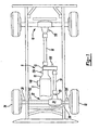
- Figure 1 is a schematic view of an exemplary motor vehicle drivetrain including a differential assembly
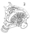
- Figure 2 is a fragmentary perspective view of a front driving axle
- FIG. 3 is a fragmentary perspective view of the front driving axle
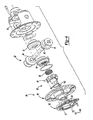
- Figure 4 is an exploded perspective view of a differential assembly
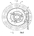
- Figure 5 is an end view of the differential assembly
- Figure 7 is a fragmentary side view of the differential assembly showing the actuating ring in a position disengaged from the side gear;
- Figure 10 is a schematic depicting a circuit including a second sensor assembly
- Figure 12 is a graph showing magnetic field density vs. distance for a second sensor assembly
- Figure 14 is a schematic diagram depicting an alternate power transmission device
- Figure 15 is a graph showing magnetic field density versus distance for a dual Hall sensor arrangement operating in a single magnetic field per Sensor Configuration 1;
- Figure 16 is a table depicting the output of the circuit of Figure 13 based on the operational state of the sensors:
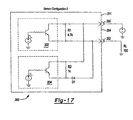
- Figure 17 is a schematic depicting an embodiment circuit for a two wire, dual sensor arrangement identified as Sensor Configuration 2;
- Figure 18 is a graph showing magnetic field density versus distance for Sensor Configuration 2;
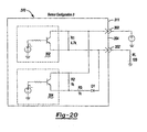
- Figure 20 is a schematic depicting an alternate embodiment circuit identified as Sensor Configuration 3;
- Figure 21 is a graph showing magnetic field density versus distance for Sensor Configuration 3.
- Figure 22 is a table depicting the output of the circuit of Figure 20 ;
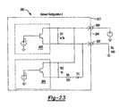
- Figure 23 is a schematic depicting an alternate embodiment circuit identified as Sensor Configuration 4.
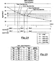
- Figure 24 is a graph showing magnetic field density versus distance for Sensor Configuration 4.
- Figure 25 is a table depicting the output of the circuit of Figure 23 ;
- Figure 26 is a schematic depicting an alternate embodiment circuit identified as Sensor Configuration 5;
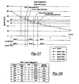
- Figure 27 is a graph showing magnetic field density versus distance for Sensor Configuration 5;
- Figure 28 is a table depicting the output of the circuit of Figure 26 ;
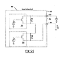
- Figure 29 is a schematic depicting another alternate embodiment circuit identified as Sensor Configuration 6;
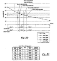
- Figure 30 is a graph showing magnetic field density versus distance for Sensor Configuration 6;
- Figure 31 is a table depicting the output of the circuit of Figure 29 ;
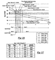
- Figure 32 is a graph showing magnetic field density versus distance for Sensor Configuration 6 where the Hall elements are programmed to have overlapping operational magnetic field ranges;
- Figure 33 is a table depicting the output of Sensor Configuration 6 having operational switch points as defined in Figure 32 ;
- Figure 34 is a graph showing magnetic field density versus distance for a circuit constructed according to Sensor Configuration 6 where the Hall effect sensors operate within dual magnetic fields;
- Figure 35 is a table depicting the output of the circuit according to Sensor Configuration 6 and Figure 34 ;
- Figure 36 is a graph showing magnetic field density versus distance for a circuit constructed according to Sensor Configuration 6 operating in dual magnetic fields where the operational magnetic field density ranges of the Hall effect sensors overlap;
- Figure 37 is a table depicting the output of the circuit according to Sensor Configuration 6 operating under the parameters defined by Figure 36 .
- the present invention is directed to an improved differential with a locking state detection system for a drivetrain of a motor vehicle.
- the differential of the present invention includes an actuator operable to place the differential in an "open” or “locked” condition.
- the detection system provides a signal indicating whether the differential is in the "open” or “locked” condition.
- the differential of the present invention may be utilized with a wide variety of driveline components and is not intended to be specifically limited to the particular application described herein.
- the actuator of the differential of the present invention may be used in conjunction with many types of differentials such as those having a bevel gear design or a parallel-axis helical design which may be of an open or limited-slip variety.
- a drivetrain 6 for an exemplary motor vehicle is shown to include an engine 8, a transmission 10, a transfer case 12, a forward propeller shaft 14 and a rearward propeller shaft 16.
- Rearward propeller shaft 16 provides torque to a rear axle assembly 18.
- Forward propeller shaft 14 provides torque from engine 8 to a pinion shaft 20 of a front axle assembly 22.
- Front axle assembly 22 includes an axle housing 24, a differential assembly 26 supported in axle housing 24 and a pair of axle shafts 28 and 30 respectively interconnected to left and right front wheels 32 and 34.
- Pinion shaft 20 has a pinion gear 36 fixed thereto which drives a ring gear 38 that is fixed to a differential case 40 of differential assembly 26.
- Differential case 40 is rotatably supported in axle housing 24 by a pair of laterally spaced bearings 41. Bearings 41 are retained by bearing caps 42 coupled to axle housing 24.
- a gearset 43 ( Figure 4 ) supported within differential case 40 transfers rotary power from differential case 40 to axle shafts 28 and 30, and facilitates relative rotation (i.e., differentiation) therebetween.
- rotary power from engine 8 is transmitted to axle shafts 28 and 30 for driving front wheels 32 and 34 via transmission 10, transfer case 12, forward propeller shaft 14, pinion shaft 20, differential case 40 and gearset 43.
- differential assembly 26 is depicted in a front-wheel drive application, the present invention is contemplated for use in differential assemblies installed in trailing axles, rear axles, transfer cases for use in four-wheel drive vehicles and/or any other known vehicular driveline application.
- Figures 4-8 depict differential assembly 26 to include differential case 40 and gearset 43.
- Gearset 43 includes a pair of pinion gears 44 rotatably supported on a cross shaft 45.
- First and second side gears 46 and 47 are drivingly interconnected to pinion gears 44 and axle shafts 28 and 30.
- Differential assembly 26 also includes an actuator and sensor assembly 48 operable to selectively couple first side gear 46 to differential case 40, thereby placing differential assembly 26 in a fully locked condition.
- a cap 49 is coupled to differential case 40 to define a pocket 50 for receipt of actuator and sensor assembly 48.
- Actuator and sensor assembly 48 includes a solenoid assembly 52, an actuating ring 54, a draw plate 56, a retainer 58 and a sensor assembly 59.
- Cap 49 includes a flange 60 coupled to a flange 62 of case 40.
- Flange 60 of cap 49 includes a recess 64 sized to receive a portion of solenoid assembly 52 during actuation.
- Cap 49 includes a pair of stepped bores 66 and 68 which define pocket 50.
- first bore 66 includes an annular surface 70 while second bore 68 includes an annular surface 72.
- First bore 66 includes an end face 74 radially inwardly extending from annular surface 70.
- An aperture 76 extends through the cap 49 and is in communication with second bore 68 where aperture 76 and second bore 68 are sized to receive a portion of the axle shaft.
- dogs 86 of actuating ring 54 are released from engagement with dogs 90 of side gear 46.
- dogs 86 engage dogs 90 to rotatably fix side gear 46 to differential case 40.
- Solenoid assembly 52 includes a metallic cup 94 and a wire coil 96.
- Wire coil 96 is positioned within cup 94 and secured thereto by an epoxy 98.
- Cup 94 includes an inner annular wall 100, an outer annular wall 102 and an end wall 104 interconnecting annular walls 100 and 102.
- Retainer 58 is a substantially disc-shaped member having an outer edge 106 mounted to end wall 104 of cup 94. A portion of retainer 58 is spaced apart from end wall 104 to define a slot 108.
- a target 126 includes a bracket 128, a magnet 130 and a fastener 132.
- Bracket 128 includes a first leg 134 having an aperture 136 extending therethrough. Fastener 132 extends through aperture 136 and is used to mount target 126 to bearing cap 42.
- Bracket 128 includes a second leg 138 positioned at a right angle to first leg 134. Second leg 138 is substantially planar and positioned substantially parallel to first face 112 of Hall element 110.
- Magnet 130 is a substantially cylindrical disk-shaped member mounted to second leg 138. Accordingly, magnet 130 includes an outer surface 139 (shown in Figure 7 ) positioned substantially parallel to first face 112.
- the sensor and magnet may be re-oriented 90 degrees to the orientation shown in the Figures. As such, the orientation of sensor and magnet shown in the drawings is merely exemplary and should not limit the scope of the invention.
- Draw plate 56 is positioned within slot 108 defined by retainer 58 and is coupled to actuating ring 54 via a plurality of fasteners 140.
- a washer 142 is positioned between cap 49 and actuating ring 54.
- washer 142 is constructed from a non-ferromagnetic material so as to reduce any tendency for actuating ring 54 to move toward end face 74 of metallic cap 49 instead of differential case 40 during energization of solenoid assembly 52.
- a bearing 144 supports cup 94 on an outer journal 146 of cap 49.
- Coil 96 is coupled to a controller 148 ( Figure 1 ) that operates to selectively energize and de-energize coil 96.
- a magnetic field is generated by current passing through coil 96.
- the magnetic field causes actuator and sensor assembly 48 to be drawn toward flange 60 of cap 49.
- solenoid assembly 52 enters recess 64
- dogs 86 of actuating ring 54 engage dogs 90 of side gear 46. Once the dogs are engaged, actuating ring 54 is in its engaged position and differential assembly 26 is in a fully locked condition as shown in Figure 8 .
- the Hall element 110 encompassed in sensor assembly 59 is spaced apart from outer surface 139 of magnet 130 by a distance "X.” At distance "X,” magnet 130 generates a predetermined magnetic field density.
- Sensor assembly 59 outputs a signal indicative of the axis) position of actuating ring 54. This signal is used by controller 148 as verification that differential assembly 26 is in a fully locked position.
- the axially moveable electromagnet provides a simplified design having a reduced number of components. Additionally, the present invention utilizes the entire differential case as the armature for the electromagnet. This allows a more efficient use of the available magnetic force. These features allow a designer to reduce the size of the electromagnet because the armature more efficiently utilizes the electromotive force supplied by the electromagnet. Such a compact design allows for minor modification of previously used components and packaging with a standard sized axle housing.
- differential assembly 26 To place differential assembly 26 in the open, unlocked condition, current is discontinued to coil 96. The magnetic field ceases to exist once current to coil 96 is stopped. At this time, compression in spring 85 causes actuator and sensor assembly 48 to axially translate and disengage dogs 86 from dogs 90. Accordingly, side gear 46 is no longer drivingly coupled to differential case 40, thereby placing differential assembly 26 in the open condition shown in Figure 7 .
- Hall element 1110 When differential assembly is in the open, unlocked condition, Hall element 1110 is positioned substantially closer to target 126 than when differential assembly 26 was in the locked position. Specifically, first face 112 is spaced apart from outer surface 139 of magnet 130 a distance "Y" when coil 96 is not energized.
- Sensor assembly 59 is configured to output a signal to controller 148 indicating that actuating ring 54 is at a position where dogs 86 are disengaged from dogs 90 and the differential is in an open condition. It should also be appreciated that actuation and deactuation times are very short due to the small number of moving components involved. Specifically, no relative ramping or actuation of other components is required to cause engagement or disengagement of dogs 86 and dogs 90.
- Electronic controller 148 controls the operation of actuator and sensor assembly 48.
- Electronic controller 148 is in receipt of data collected by a first speed sensors. 150 and a second speed sensor 152 as shown in Figure 1 .
- First speed sensor 150 provides data corresponding to the rotational speed of axle shaft 28.
- second speed sensor 152 measures the rotational speed of axle shaft 30 and outputs a signal to controller 148 indicative thereof.
- controller 148 will determine if an electrical signal is sent to coil 96.
- Controller 148 compares the measured or calculated parameters to predetermined values and outputs an electrical signal to place differential assembly 26 in the locked position only when specific conditions are met. As such, controller 148 assures that an "open” condition is maintained when events such as anti-lock braking occur. The "open” condition is verified by the signal output from sensor assembly 59. Limiting axis differentiation during anti-lock braking would possibly counteract the anti-look braking system. Other such situations may be programmed within controller 148.
- coil 162 does not axially translate nor rotate during any mode of operation of differential assembly 160.
- An axially moveable armature 168 is coupled to actuating ring 54.
- Armature 168 is shaped as an annular flat ring positioned proximate coil 162.
- Armature 168 and actuating ring 54 are drivingly coupled to differential case 40 and axially moveable relative to coil 162 and differential case 40.
- Armature 168 and actuating ring 54 are biased toward a disengaged, open differential, position shown in Figure 9 by a compression spring as previously described in relation to differential assembly 26.
- the power transmitting device of the present invention is not limited to such an application.
- the present invention may be used in rear drive axles, transaxles for front-wheel drive vehicles, transfer cases for use in four-drive vehicles and/or a number of other vehicular driveline application.
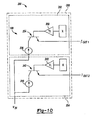
- Figure 10 depicts a circuit 198 having a second sensor assembly 200.
- Sensor assembly 200 includes a first Hall element 202, a second Hall element 204 and a body 206 encompassing both of the Hall elements.
- Sensor assembly 200 is shaped substantially similarly to sensor assembly 59.
- Sensor assembly 200 is positioned in communication with a differential assembly in a substantially similar manner to sensor assembly 59. Accordingly, the description relating to the mounting of sensor assembly 200 within the axle assembly will not be reiterated.
- Hall effect device Due to the nature of Hall effect devices, permanent magnets and the general environment in which sensor assembly 200 is required to function, a very large mechanical hysteresis is inherent in the system. Mechanical hysteresis in this instance is best described as the absolute distance the sensor assembly must travel in relation to the target magnet in order to change its output state.
- the Hall effect device switches state, or outputs a different signal, based on the Hall element being exposed to a changing magnetic field density.
- the Hall effect device may be configured to start switching at a predetermined magnetic field density described as its operating point (Bop) and the field density must change an amount equal to the inherent hysteresis (Bhys) of the Hall effect device in order to switch.
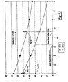
- Figure 11 is a graph showing magnetic field density versus distance for the first sensor assembly 59 shown in Figures 4-8 .
- permanent magnet 130 generates an exponentially decaying field density, measured in gauss versus the distance traveled in millimeters. For example, if Hall element 110 was programmed to switch at a Bop of 80 gauss and had a Bhys of 10 gauss, Hall element 110 would initiate a switch at 80 gauss and change its state at 70 gauss. Because a magnetic field is generated when coil 96 is energized, two distinct gauss curves are created. The upper curve depicts the field density present when the electro-magnet of solenoid assembly 52 is energized.
- the lower curve represents the magnetic field density generated by the permanent magnet alone when the coil 96 is not energized.
- a relatively large hysteresis is introduced into the system by operation of solenoid assembly 52.
- the magnitude of hysteresis introduced is by choice. It should be appreciated that the coil may be wired in the opposite polarity to reduce the relative gap between the gauss curves.
- sensor assembly 59 moves from a location where distance "Y” equals 4mm and distance "X” equal 8mm. Sensor assembly 59 does not output a signal indicating that the differential assembly is in the locked condition until sensor assembly 59 reaches a distance of 7.8mm of spacing between first face 112 and outer surface 139. During coil 96 deenergization, sensor assembly 59 does not output a signal indicating that the differential assembly is unlocked until the spacing between the Hall element and the permanent magnet is 4.8mm. As such, a total mechanical hysteresis of approximately 3mm exists with the single sensor arrangement Depending on the operational characteristics of the mechanical system including sensor assembly 59, this magnitude of hysteresis may or may be acceptable.
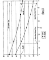
- Figure 12 is a graph showing magnetic field density versus distance for the second sensor assembly 200 shown in Figure 10 .
- Hall elements 202 and 204 of sensor assembly 200 are configured in accordance with Figures 10 and 12 .
- First Hall element 202 is set to have an operating point of 60 gauss while second Hall element 204 is set to have an operating point of 100 gauss.
- second Hall element 204 outputs a signal indicating that the differential assembly is in the locked condition once the magnetic field density reduces from 100 gauss to 90 gauss. This condition occurs when the spacing between second Hall element 204 and outer surface 139 of magnet 130 is approximately 6.3mm.
- first Hall element 202 outputs a signal indicative of an open differential condition once the magnetic field density changes from 50 to 60 gauss. This condition exists when first Hall element 202 is spaced from outer surface 139 a distance of approximately 5.6mm.
- first Hall element 202 is spaced from outer surface 139 a distance of approximately 5.6mm.
- the total mechanical hysteresis is now approximately 0.75mm when using two Hall elements with different operating points.
- the circuit 198 depicted in Figure 10 includes first Hall effect sensor 202 and second Hall effect sensor 204.
- First Hall effect sensor 202 is coupled in series with a differential gain amplifier 232.
- Differential gain amplifier 232 is coupled to the base of a current gain transistor 234.
- a constant current source 236 is supplied to the collector leg of current gain transistor 234.
- the emitter leg of current gain transistor 234 provides an output signal labeled as I OUT1 .
- second Hall effect sensor 204 is connected in series with a differential gain amplifier 240.
- Differential gain amplifier 240 is coupled to the base of a current gain transistor 242.
- Constant current source 236 is supplied to the collector leg of current gain transistor 242, The emitter leg of current gain transistor 242 provides an output signal labeled as I OUT2 .
- Controller 148 analyzes I OUT1 and I OUT2 to determine the operating mode of differentiation as being locked or unlocked. When both I OUT1 and I OUT2 are low or zero, controller 148 determines that the differential is operating in the locked mode. When I OUT1 and I OUT2 are both high or one, controller 148 determines that the differential is operating in the unlocked mode.
- Figure 13 depicts an alternate dual Hall sensor circuit 300 operable to output a signal indicative of the position of a moveable member within a power transmission device.
- Circuit 300 may be implemented in conjunction with the lockable differential assembly previously described. Furthermore, it is contemplated that circuit 300 may be used in conjunction with any number of power transmission subsystems that include an axially moveable member.
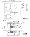
- Figure 14 shows a power transmission device 306 operable to selectively transfer torque from a first rotatable shaft 308 to a second rotatable shaft 310.
- the rotatable shafts are at least partially positioned within a housing 311 and are selectively drivingly interconnected by a clutch assembly 312.
- Clutch assembly 312 incudes a plurality of outer friction plates 314 slidably coupled to second shaft 310 and a plurality of inner friction plates 316 slidably coupled to shaft 308.
- Outer plates 314 are interleaved with inner plates 316.
- An actuator 318 is operable to axially displace an apply plate 320 such that a compressive force may be selectively applied to the clutch 312.
- the output torque of clutch 312 may be varied according to the input force generated by actuator 318.
- a sensor assembly 322 is mounted to housing 311.
- a target 324 is mounted to axially moveable apply plate 320.
- actuator 318 is operable to move apply plate 320 between at least three discrete positions. These positions are represented by target 324 being shown In solid line representation when apply plate 320 is at the first or returned position where no torque is transferred through clutch 312, a second position as denoted by target 324' in hidden line representation and a third position shown as target 324" also in hidden lines.
- actuator 318 moves apply plate 320 to take up axial clearance between outer plates 314 and inner plates 316 to place the clutch in a ready mode.
- clutch 312 transmits minimal torque, If any, between shaft 308 and shaft 310.
- a sensor circuit operable to output signals indicating when an axially moveable member such as apply plate 320 is at one of three locations.
- an axially moveable member such as apply plate 320 is at one of three locations.
- only two locations may need to be determined if the sensor arrangement is used in a device such as differential assemblies 26 or 160 because the axially moveable actuating ring 54 is typically in one of two locations.
- Actuating ring 54 is either in the fully returned position when the differential is in an open condition or the fully advanced position when the differential is in the locked condition.
- the circuit may output signals indicating that the target is in one of two different zones or that the target is located within one of three different zones of linear position.
- Figure 16 represents a state diagram defining the output of circuit 300 based on the operational states of sensor 302 and sensor 304.
- the table of Figure 16 identifies sensor 302 as sensor 1 and sensor 304 as sensor 2.
- Configuration 1 outputs 5 mA when the distance between the Hall effect sensors and the target is within zone 1 or 2.
- Both sensor 302 and sensor 304 are in the OFF state when the distance between the Hall effect sensors and the target is within zone 3.
- Iout equals 15 mA. Because the Hall effect sensors include inherent hysteresis, the distance at which the state of the sensor changes depends on whether the magnetic field density is increasing or decreasing.
- zones 1, 2 and 3 vary slightly depending on the direction of travel of the axially moveable member.
- sensor 2 switches from the ON state to the OFF state after the magnetic field density changes from Bop to Bhys.
- This change represents the spacing between the Hall effect sensor and the target as increasing at the point of transition from zone 2 to zone 3 as shown at approximately 1.75 mm.
- sensor 2 is shown to switch from the OFF to the ON state only after the magnetic field density increases from Bhys to Bop. This condition is shown to occur at approximately a 1.3 mm spacing as zone 3' is exited and zone 2' is entered.
- the beginning of zone 3 does not exactly correspond to the ending of zone 3'. This "tolerance" of the distance at which zone 2 ends and zone 3 starts should be accounted for in the logic of the controller utilizing the information output from circuit 300.
- Figure 19 includes another column entitled Alternate Sensor Iout which represents the output of circuit 360 if the operating points of sensors 1 and 2 were switched.
- Iout equals 5 mA when the spacing between the Hall effect sensors and the target is within zone 1.
- Iout equals 15 mA when the spacing between the sensors and the target is within zone 2.
- Iout equals 21 mA when the spacing between the sensors and the target is within zone 3.
- the versatility of the use of two programmable Hall effect sensors is illustrated by reviewing the Alternate Sensor Iout column and noting that the same circuit may be used to provide an indication when the spacing between Hall sensors is within one of two areas.
- Sensor Configuration 2 is easily programmed to provide a two position sensing arrangement or a three position sensing arrangement.
- Circuit 370 or Sensor Configuration 3 is substantially similar to Sensor Configurations 1 and 2 with minor changes to the circuit. The circuit modifications cause the magnitude of the output current levels to change. Furthermore, different sensor state combinations provide different outputs.
- the Sensor Iout column shows that 3 mA is output in zone 1 and zone 1' while 21 mA will be output when the spacing between the sensor and the target is within zone 2, zone 2', zone 3 or zone 3'.
- Figures 23-25 relate to Sensor Configuration 4 having a circuit 380.
- Figures 26-28 correspond to Sensor Configuration 5 having a circuit 390.
- Figures 29-31 depict Sensor Configuration 6 having a circuit 395.
- Sensor Configurations 4, 5 and 6 further illustrate the versatility of the present invention by constructing simple circuits using two Hall elements to output signals indicative of the position of an axially moveable component within a power transmission device.
- Figures 32 and 33 depict a method of adjusting the width of certain detection zones by modifying the operating switch point of one sensor relative to the other.
- the embodiments previously described included a first sensor having an operating range of magnetic field density defined by its operating point and its hysteresis switch point.
- the operating range of sensor 1 is spaced apart from the operating range of magnetic field density of sensor 2 because sensor 2 is purposefully configured with different operating and hysteresis switch points.
- Sensor Configuration 6 is shown to include the operating switch point of sensor 2 being programmed to lie within the operating range of magnetic field density defined by sensor 1.
- sensor 2 has an operating point (Bop) that is greater than the hysteresis switch point (Bhys) of sensor 1 but lower than the operating switch point (Bop) of sensor 1.
- Bop operating point
- the axial travel defined by zone 2 is greatly reduced.
- the distance traveled to exit zone 1, pass entirely through zone 2 and enter zone 3 is approximately .5 mm. Accordingly, the dual Hall sensor arrangement having overlapping operating ranges may be useful for an application where relatively small axial distances are traveled by the axially moveable member.
- Figures 34-37 illustrate that any one of the Sensor Configurations 1-6 may also be used in a dual field operation mode. These Figures also illustrate that the operating ranges of the Hall sensors may be overlapped or not overlapped in the dual field mode of operation as well as the single field mode of operation.
- the dual field operation mode was described in greater detail previously in reference to the lockable differential having an electromagnet with a coil operable to generate an electromagnetic field. However, in this embodiment the polarity of the permanent magnet and the electromagnet are positioned such that the magnetic field density at the sensors decreases when the electromagnet coil is on.
Landscapes
- Engineering & Computer Science (AREA)
- General Engineering & Computer Science (AREA)
- Mechanical Engineering (AREA)
- Physics & Mathematics (AREA)
- General Physics & Mathematics (AREA)
- Electromagnetism (AREA)
- Retarders (AREA)
- Measurement Of Length, Angles, Or The Like Using Electric Or Magnetic Means (AREA)
- Locating Faults (AREA)
- Push-Button Switches (AREA)
- Arrangement And Mounting Of Devices That Control Transmission Of Motive Force (AREA)
Claims (15)
- Achsaggregat (18, 22), welches umfasst:ein Gehäuse (24, 311);eine erste Welle (28, 308), die in dem Gehäuse (24, 311) drehbar positioniert ist;eine zweite Welle (30, 310), die in dem Gehäuse (24, 311) drehbar positioniert ist;eine Kupplung (26, 160, 306), die in dem Gehäuse positioniert ist, wobei die Kupplung betreibbar ist, um die erste Welle (28, 308) mit der zweiten Welle (30, 310) selektiv zu koppeln, wobei die Kupplung (26, 160, 306) in einem ersten Modus betreibbar ist, in dem die erste Welle (28, 308) mit der zweiten Welle (30, 310) gemeinsam dreht, wobei die Kupplung (28, 160, 306) auch in einem zweiten Modus betreibbar ist, der sich von dem ersten Modus unterscheidet;einen Aktuator (52, 318) mit einem linear beweglichen Element (54, 320), das zwischen einer ersten Position, die die Kupplung (26, 160, 306) in dem ersten Modus arbeiten lässt, und einer zweiten Position, die die Kupplung (26, 160, 306) in dem zweiten Modus arbeiten lässt, beweglich ist, wobei der Aktuator (52, 318) betreibbar ist, um das linear bewegliche Element (54, 320) zwischen der ersten und zweiten Position zu bewegen; undeine Sensorschaltung (360, 380, 390, 395), die in dem Gehäuse (24, 311) positioniert ist, wobei die Sensorschaltung (360, 380) zwei elektrisch miteinander verbundene Halleffektvorrichtungen (302, 304) umfasst, die dafür ausgelegt sind, die lineare Position des beweglichen Elements (54, 320) zu erfassen, und dafür ausgelegt sind, ein Ausgangssignal zu erzeugen, das eine Position des beweglichen Elements (54, 320) anzeigt, wobei das Ausgangssignal einen ersten Wert aufweist, wenn sich das bewegliche Element (54, 320) in der ersten Position befindet, das Ausgangssignal einen zweiten Wert aufweist, wenn sich das bewegliche Element (54, 320) in der zweiten Position befindet, und das Ausgangssignal einen dritten Wert aufweist, wenn sich das bewegliche Element (54, 320) in einer Position befindet, die zwischen der ersten und zweiten Position liegt.
- Achsaggregat (18, 22) nach Anspruch 1, dadurch gekennzeichnet, dass die Halleffektvorrichtungen (302, 304) elektrisch parallel geschaltet sind.
- Achsaggregat (18, 22) nach Anspruch 1, dadurch gekennzeichnet, dass die Halleffektvorrichtungen (302, 304) elektrisch in Reihe geschaltet sind.
- Achsaggregat (18, 22) nach einem der vorhergehenden Ansprüche, dadurch gekennzeichnet, dass eine erste der Halleffektvorrichtungen (302, 304) zwischen Schaltzuständen einem ersten Betriebsbereich von Magnetfelddichte zugeordnet ist und eine zweite der Halleffektvorrichtungen (302, 304) zwischen Schaltzuständen einem zweiten Betriebsbereich von Magnetfelddichte zugeordnet ist und dass sich der erste Betriebsbereich mit dem zweiten Betriebsbereich überschneidet.
- Achsaggregat (18, 22) nach einem der Ansprüche 1 bis 3, dadurch gekennzeichnet, dass eine erste der Halleffektvorrichtungen (302, 304) zwischen Schaltzuständen einem ersten Betriebsbereich von Magnetfelddichte zugeordnet ist und eine zweite der Halleffektvorrichtungen (302, 304) zwischen Schaltzuständen einem zweiten Betriebsbereich von Magnetfelddichte zugeordnet ist und dass sich der erste Betriebsbereich nicht mit dem zweiten Betriebsbereich überschneidet.
- Achsaggregat (18, 22) nach Anspruch 1, dadurch gekennzeichnet, dass jede der Malleffektvorrichtungen (302, 304) eine Eingangsklemme und eine Ausgangsklemme umfasst und dass ein erster Widerstand (R1) die Eingangs- und Ausgangsklemme einer der Halleffektvorrichtungen (302, 304) elektrisch verbindet.
- Achsaggregat (18, 22) nach Anspruch 6, dadurch gekennzeichnet, dass ein zweiter Widerstand (R2) die Eingangs- und Ausgangsklemme einer zweiten der Halleffektvorrichtungen (302, 304) elektrisch verbindet.
- Achsaggregat (18, 22) nach Anspruch 7, dadurch gekennzeichnet, dass der erste Widerstand (R1) einen Widerstand einer ersten Größenordnung aufweist und der zweite Widerstand (R2) einen Widerstand einer zweiten Größenordnung aufweist, die sich von der ersten Größenordnung unterscheidet.
- Achsaggregat (18, 22) nach einem der vorhergehenden Ansprüche, dadurch gekennzeichnet, dass der Aktuator (52, 318) einen Elektromagneten umfasst.
- Achsaggregat (18, 22) nach einem der vorhergehenden Ansprüche, welches weiterhin ein Differential (26, 160) umfasst, das mit der Kupplung (26, 160, 306) gekoppelt ist.
- Achsaggregat (18, 22) nach einem der vorhergehenden Ansprüche, dadurch gekennzeichnet, dass die Kupplung (26, 160, 306) einen Satz formschlüssiger Klauen (86, 90) umfasst.
- Achsaggregat (18, 22) nach einem der Ansprüche 1 bis 9, dadurch gekennzeichnet, dass die Kupplung (26, 160, 306) mehrere erste Reibscheiben (316), die mit der ersten Welle (28, 308) verbunden sind, und mehrere zweite Reibscheiben (314), die mit der zweiten Welle (30, 310) verbunden sind, umfasst und dass die ersten Reibescheiben (316) mit den zweiten Reibscheiben (314) verschränkt sind.
- Achsaggregat (18, 22) nach einem der vorhergehenden Ansprüche, dadurch gekennzeichnet, dass das Ausgangssignal ein elektrischer Strom ist.
- Verfahren zum Detektieren des Betriebszustand eines Achsaggregats (16, 22), wobei das Achsaggregat (18, 22) umfasst: eine erste Welle (28, 311), eine zweite Welle (30, 310), eine Kupplung (26, 160, 306), einen Aktuator (52, 318) und eine Sensorschaltung (360, 380, 390, 395), wobei die Kupplung (26, 160, 306) in einem ersten Modus betreibbar ist, in dem die erste Welle (28, 308) mit der zweiten Welle (30, 310) gemeinsam dreht, wobei die Kupplung (26, 160, 306) auch in einem zweiten Modus betreibbar ist, der sich von dem ersten Modus unterscheidet, wobei der Aktuator (52, 318) ein linear bewegliches Element (54, 320) aufweist, das zwischen einer ersten Position, die die Kupplung (26, 180, 306) in dem ersten Modus arbeiten lässt, und einer zweiten Position, die die Kupplung (26, 160, 306) in dem zweiten Modus arbeiten lässt, beweglich ist, wobei der Aktuator (52, 318) betreibbar ist, um das linear bewegliche Element (54, 320) zwischen der ersten und zweiten Position zu bewegen, wobei die Sensorschaltung (360, 380, 390, 395) zwei elektrisch miteinander verbundene Halleffektvorrichtungen (302, 304) umfasst, die dafür ausgelegt sind, die lineare Position des beweglichen Elements (54, 320) zu erfassen, wobei das Verfahren umfasst:Ausgeben eines ersten Signals von der Sensorschaltung (360, 380, 390, 395), wenn das linear bewegliche Element (54, 320) in einer ersten Position positioniert ist;Ausgeben eines zweiten Signals von der Sensorschaltung (360, 380, 390, 395), wenn das linear bewegliche Element (54, 320) in einer zweiten Position positioniert ist, wobei sich das zweite Signal von dem ersten Signal unterscheidet; undAusgeben eines dritten Signals von der Sensorschaltung (360, 380, 390, 395), wenn das linear bewegliche Element (54, 320) in einer dritten Position positioniert ist, wobei sich das dritte Signal von dem ersten und zweiten Signal unterscheidet.
- Verfahren nach Anspruch 14, dadurch gekennzeichnet, dass eine Größenordnung des zweiten Signals zwischen einer Größenordnung des ersten Signals und einer Größenordnung des dritten Signals liegt.
Applications Claiming Priority (2)
| Application Number | Priority Date | Filing Date | Title |
|---|---|---|---|
| US11/359,907 US7507176B2 (en) | 2005-05-26 | 2006-02-22 | Two wire dual sensor differential locking state detection system |
| PCT/US2007/004358 WO2007100545A2 (en) | 2006-02-22 | 2007-02-20 | Two wire dual sensor differential locking state detection system |
Publications (3)
| Publication Number | Publication Date |
|---|---|
| EP2002155A2 EP2002155A2 (de) | 2008-12-17 |
| EP2002155A4 EP2002155A4 (de) | 2009-07-29 |
| EP2002155B1 true EP2002155B1 (de) | 2010-04-21 |
Family
ID=38459515
Family Applications (1)
| Application Number | Title | Priority Date | Filing Date |
|---|---|---|---|
| EP07751140A Active EP2002155B1 (de) | 2006-02-22 | 2007-02-20 | Zweidraht-dual-sensor-system zur erkennung eines differentialsperrzustands |
Country Status (6)
| Country | Link |
|---|---|
| US (2) | US7507176B2 (de) |
| EP (1) | EP2002155B1 (de) |
| AT (1) | ATE465360T1 (de) |
| CA (1) | CA2643349A1 (de) |
| DE (1) | DE602007005997D1 (de) |
| WO (1) | WO2007100545A2 (de) |
Families Citing this family (12)
| Publication number | Priority date | Publication date | Assignee | Title |
|---|---|---|---|---|
| US7602271B2 (en) | 2006-08-21 | 2009-10-13 | American Axle & Manufacturing, Inc. | Electronically actuated apparatus using solenoid actuator with integrated sensor |
| US7837585B2 (en) * | 2006-11-27 | 2010-11-23 | American Axle & Manufacturing, Inc. | Linear actuator with position sensing system |
| US7572202B2 (en) * | 2007-01-31 | 2009-08-11 | American Axle & Manufacturing, Inc. | Electronic locking differential with direct locking state detection system |
| US8897974B2 (en) * | 2010-06-07 | 2014-11-25 | Gm Global Technology Operations, Llc | Gear selector system |
| JP6218813B2 (ja) * | 2012-05-23 | 2017-10-25 | イートン コーポレーションEaton Corporation | 非回転の固定子及び電機子を有する電子作動式ロッキングディファレンシャル |
| WO2015130847A1 (en) | 2014-02-25 | 2015-09-03 | Dana Automotive Systems Group, Llc | Modular electronic differential control system |
| CN104129287B (zh) * | 2014-07-31 | 2017-01-11 | 浙江信阳实业有限公司 | 车辆后桥差速装置 |
| US10488224B2 (en) | 2015-05-29 | 2019-11-26 | Dana Automotive Systems Group, Llc | Apparatus for sensing the position of an actuator assembly of a locking gearset |
| JP2020519818A (ja) | 2017-05-09 | 2020-07-02 | デーナ、オータモウティヴ、システィムズ、グループ、エルエルシー | 差動センサ装置および使用方法 |
| US10473203B2 (en) | 2017-12-12 | 2019-11-12 | Gkn Automotive Limited | Vehicle differential having an electromagnetic actuator |
| US11195350B2 (en) * | 2020-04-13 | 2021-12-07 | Dana Automotive Systems Group, Llc | System and method for controlling a locking differential of an axle |
| US12018738B2 (en) | 2020-06-16 | 2024-06-25 | American Axle & Manufacturing, Inc. | Vehicle driveline component having a sensor-less electromagnetic actuator system |
Family Cites Families (21)
| Publication number | Priority date | Publication date | Assignee | Title |
|---|---|---|---|---|
| US3732752A (en) | 1971-07-26 | 1973-05-15 | Gen Motors Corp | Locking type differential gear mechanism |
| US4733101A (en) * | 1986-11-17 | 1988-03-22 | General Motors Corporation | Vehicle power antenna control with inhibit during cranking |
| US5157966A (en) | 1990-02-20 | 1992-10-27 | The Torrington Company | Transmission speed sensor |
| GB2270958B (en) * | 1992-09-29 | 1996-02-14 | Borg Warner Automotive | Power transmitting assembly |
| DE19626341A1 (de) | 1996-07-01 | 1998-01-08 | Claas Ohg | Vorrichtung und Verfahren zur selbsttätigen Steuerung einer Differentialsperre in Antriebsachsen eines Kraftfahrzeugs |
| US5867092A (en) | 1996-08-30 | 1999-02-02 | Borg-Warner Automotive, Inc. | Hall effect transfer case shift mechanism position sensor |
| JPH11118818A (ja) | 1997-10-14 | 1999-04-30 | Toyota Autom Loom Works Ltd | 車両における回転数検出用センサの取付構造及び歯車 |
| US5989147A (en) | 1998-02-25 | 1999-11-23 | Auburn Gear, Inc. | Electronically controllable limited slip differential |
| US5984823A (en) | 1998-08-27 | 1999-11-16 | American Axle & Manufacturing, Inc. | Differential with shaft locking mechanism |
| US6334832B1 (en) | 2000-05-31 | 2002-01-01 | Warn Industries, Inc. | Control for vehicle differential |
| US6309321B1 (en) | 2000-08-11 | 2001-10-30 | Tractech Inc | Fully-locking torque-proportioning differential |
| US6428441B1 (en) | 2000-08-28 | 2002-08-06 | Spicer Technology, Inc. | Locking differential with clutch activated by magnetorheological fluid |
| US20040132572A1 (en) | 2003-01-02 | 2004-07-08 | Eaton Corporation | Lock detection sensor |
| US6958030B2 (en) * | 2003-09-29 | 2005-10-25 | American Axle & Manufacturing, Inc. | Electromagnetic locking differential assembly |
| US7022040B2 (en) * | 2003-09-29 | 2006-04-04 | American Axle & Manufacturing, Inc. | Locking differential with electromagnetic actuator |
| US7059998B2 (en) * | 2004-03-24 | 2006-06-13 | General Motors Corporation | DOD control methods for manual transmissions |
| US7021440B2 (en) * | 2004-08-17 | 2006-04-04 | Ntn Corporation | Electronic locking clutch with lock indication device |
| US7152720B2 (en) | 2005-01-08 | 2006-12-26 | Dana Corporation | Automated inter-axle differential lock actuation sensing method |
| US7211020B2 (en) * | 2005-05-26 | 2007-05-01 | American Axle & Manufacturing, Inc. | Lockable differential with locking state detection system |
| US7384359B2 (en) * | 2005-05-26 | 2008-06-10 | American Axle & Manufacturing, Inc. | Method and apparatus for transmitting axle sensor data |
| US7357749B2 (en) | 2005-12-15 | 2008-04-15 | Eaton Corporation | Limited slip differential and engagement sensing mechanism therefor |
-
2006
- 2006-02-22 US US11/359,907 patent/US7507176B2/en not_active Expired - Lifetime
-
2007
- 2007-02-20 WO PCT/US2007/004358 patent/WO2007100545A2/en not_active Ceased
- 2007-02-20 CA CA002643349A patent/CA2643349A1/en not_active Abandoned
- 2007-02-20 DE DE602007005997T patent/DE602007005997D1/de active Active
- 2007-02-20 EP EP07751140A patent/EP2002155B1/de active Active
- 2007-02-20 AT AT07751140T patent/ATE465360T1/de not_active IP Right Cessation
-
2009
- 2009-03-20 US US12/408,144 patent/US7878314B2/en not_active Expired - Lifetime
Also Published As
| Publication number | Publication date |
|---|---|
| EP2002155A2 (de) | 2008-12-17 |
| ATE465360T1 (de) | 2010-05-15 |
| WO2007100545A2 (en) | 2007-09-07 |
| US20060270509A1 (en) | 2006-11-30 |
| CA2643349A1 (en) | 2007-09-07 |
| DE602007005997D1 (de) | 2010-06-02 |
| US7507176B2 (en) | 2009-03-24 |
| EP2002155A4 (de) | 2009-07-29 |
| US20090181818A1 (en) | 2009-07-16 |
| WO2007100545A3 (en) | 2008-11-13 |
| US7878314B2 (en) | 2011-02-01 |
Similar Documents
| Publication | Publication Date | Title |
|---|---|---|
| EP2002155B1 (de) | Zweidraht-dual-sensor-system zur erkennung eines differentialsperrzustands | |
| EP1994305B1 (de) | Verfahren und vorrichtung zum übertragen von achsensensordaten | |
| EP1726851B1 (de) | Sperrdifferenzial mit Erfassung der Position des Sperrelements | |
| EP1580458B1 (de) | Sperrdifferential mit elektromagnetischem Betätigungsglied | |
| US7137921B2 (en) | Electromagnetic locking differential assembly | |
| EP2059939B1 (de) | Elektronisch betätigte vorrichtung mit einem elektromagnetischen stellglied mit integriertem sensor | |
| KR19980018406A (ko) | 자동 파워 트레인의 자동화 부품을 위한 작동장치 | |
| CN112896137A (zh) | 耦合和控制组件及其使用方法 | |
| EP3807599B1 (de) | Differenzial mit ankerpositionsbestimmung | |
| US20140144259A1 (en) | Two position actuator with sensing and control | |
| CN106499745B (zh) | 电磁线圈组件以及操作方法 | |
| JP6704931B2 (ja) | 電子制御式車両用変速機 | |
| JP2019511688A (ja) | センサを含むカップリング制御組立体 |
Legal Events
| Date | Code | Title | Description |
|---|---|---|---|
| PUAI | Public reference made under article 153(3) epc to a published international application that has entered the european phase |
Free format text: ORIGINAL CODE: 0009012 |
|
| 17P | Request for examination filed |
Effective date: 20080919 |
|
| AK | Designated contracting states |
Kind code of ref document: A2 Designated state(s): AT BE BG CH CY CZ DE DK EE ES FI FR GB GR HU IE IS IT LI LT LU LV MC NL PL PT RO SE SI SK TR |
|
| AX | Request for extension of the european patent |
Extension state: AL BA HR MK RS |
|
| R17D | Deferred search report published (corrected) |
Effective date: 20081113 |
|
| RIC1 | Information provided on ipc code assigned before grant |
Ipc: G06F 17/00 20060101ALI20090109BHEP Ipc: F16H 48/20 20060101ALI20090109BHEP Ipc: G06F 7/00 20060101ALI20090109BHEP Ipc: G05D 1/00 20060101ALI20090109BHEP Ipc: B60T 7/12 20060101ALI20090109BHEP Ipc: F16H 48/06 20060101AFI20090109BHEP |
|
| A4 | Supplementary search report drawn up and despatched |
Effective date: 20090629 |
|
| RIC1 | Information provided on ipc code assigned before grant |
Ipc: F16H 48/24 20060101ALN20090623BHEP Ipc: F16H 48/20 20060101ALN20090623BHEP Ipc: F16H 48/30 20060101AFI20090623BHEP Ipc: F16H 48/08 20060101ALN20090623BHEP Ipc: F16H 48/06 20060101ALN20090623BHEP |
|
| GRAP | Despatch of communication of intention to grant a patent |
Free format text: ORIGINAL CODE: EPIDOSNIGR1 |
|
| DAX | Request for extension of the european patent (deleted) | ||
| GRAS | Grant fee paid |
Free format text: ORIGINAL CODE: EPIDOSNIGR3 |
|
| GRAA | (expected) grant |
Free format text: ORIGINAL CODE: 0009210 |
|
| AK | Designated contracting states |
Kind code of ref document: B1 Designated state(s): AT BE BG CH CY CZ DE DK EE ES FI FR GB GR HU IE IS IT LI LT LU LV MC NL PL PT RO SE SI SK TR |
|
| REG | Reference to a national code |
Ref country code: GB Ref legal event code: FG4D |
|
| REG | Reference to a national code |
Ref country code: CH Ref legal event code: EP |
|
| REG | Reference to a national code |
Ref country code: IE Ref legal event code: FG4D |
|
| REF | Corresponds to: |
Ref document number: 602007005997 Country of ref document: DE Date of ref document: 20100602 Kind code of ref document: P |
|
| REG | Reference to a national code |
Ref country code: NL Ref legal event code: VDEP Effective date: 20100421 |
|
| LTIE | Lt: invalidation of european patent or patent extension |
Effective date: 20100421 |
|
| PG25 | Lapsed in a contracting state [announced via postgrant information from national office to epo] |
Ref country code: LT Free format text: LAPSE BECAUSE OF FAILURE TO SUBMIT A TRANSLATION OF THE DESCRIPTION OR TO PAY THE FEE WITHIN THE PRESCRIBED TIME-LIMIT Effective date: 20100421 Ref country code: SE Free format text: LAPSE BECAUSE OF FAILURE TO SUBMIT A TRANSLATION OF THE DESCRIPTION OR TO PAY THE FEE WITHIN THE PRESCRIBED TIME-LIMIT Effective date: 20100421 Ref country code: ES Free format text: LAPSE BECAUSE OF FAILURE TO SUBMIT A TRANSLATION OF THE DESCRIPTION OR TO PAY THE FEE WITHIN THE PRESCRIBED TIME-LIMIT Effective date: 20100801 Ref country code: NL Free format text: LAPSE BECAUSE OF FAILURE TO SUBMIT A TRANSLATION OF THE DESCRIPTION OR TO PAY THE FEE WITHIN THE PRESCRIBED TIME-LIMIT Effective date: 20100421 |
|
| PG25 | Lapsed in a contracting state [announced via postgrant information from national office to epo] |
Ref country code: LV Free format text: LAPSE BECAUSE OF FAILURE TO SUBMIT A TRANSLATION OF THE DESCRIPTION OR TO PAY THE FEE WITHIN THE PRESCRIBED TIME-LIMIT Effective date: 20100421 Ref country code: FI Free format text: LAPSE BECAUSE OF FAILURE TO SUBMIT A TRANSLATION OF THE DESCRIPTION OR TO PAY THE FEE WITHIN THE PRESCRIBED TIME-LIMIT Effective date: 20100421 Ref country code: SI Free format text: LAPSE BECAUSE OF FAILURE TO SUBMIT A TRANSLATION OF THE DESCRIPTION OR TO PAY THE FEE WITHIN THE PRESCRIBED TIME-LIMIT Effective date: 20100421 Ref country code: IS Free format text: LAPSE BECAUSE OF FAILURE TO SUBMIT A TRANSLATION OF THE DESCRIPTION OR TO PAY THE FEE WITHIN THE PRESCRIBED TIME-LIMIT Effective date: 20100821 Ref country code: AT Free format text: LAPSE BECAUSE OF FAILURE TO SUBMIT A TRANSLATION OF THE DESCRIPTION OR TO PAY THE FEE WITHIN THE PRESCRIBED TIME-LIMIT Effective date: 20100421 |
|
| PG25 | Lapsed in a contracting state [announced via postgrant information from national office to epo] |
Ref country code: PL Free format text: LAPSE BECAUSE OF FAILURE TO SUBMIT A TRANSLATION OF THE DESCRIPTION OR TO PAY THE FEE WITHIN THE PRESCRIBED TIME-LIMIT Effective date: 20100421 Ref country code: CY Free format text: LAPSE BECAUSE OF FAILURE TO SUBMIT A TRANSLATION OF THE DESCRIPTION OR TO PAY THE FEE WITHIN THE PRESCRIBED TIME-LIMIT Effective date: 20100602 |
|
| PG25 | Lapsed in a contracting state [announced via postgrant information from national office to epo] |
Ref country code: PT Free format text: LAPSE BECAUSE OF FAILURE TO SUBMIT A TRANSLATION OF THE DESCRIPTION OR TO PAY THE FEE WITHIN THE PRESCRIBED TIME-LIMIT Effective date: 20100823 Ref country code: DK Free format text: LAPSE BECAUSE OF FAILURE TO SUBMIT A TRANSLATION OF THE DESCRIPTION OR TO PAY THE FEE WITHIN THE PRESCRIBED TIME-LIMIT Effective date: 20100421 Ref country code: EE Free format text: LAPSE BECAUSE OF FAILURE TO SUBMIT A TRANSLATION OF THE DESCRIPTION OR TO PAY THE FEE WITHIN THE PRESCRIBED TIME-LIMIT Effective date: 20100421 |
|
| PLBE | No opposition filed within time limit |
Free format text: ORIGINAL CODE: 0009261 |
|
| STAA | Information on the status of an ep patent application or granted ep patent |
Free format text: STATUS: NO OPPOSITION FILED WITHIN TIME LIMIT |
|
| PG25 | Lapsed in a contracting state [announced via postgrant information from national office to epo] |
Ref country code: SK Free format text: LAPSE BECAUSE OF FAILURE TO SUBMIT A TRANSLATION OF THE DESCRIPTION OR TO PAY THE FEE WITHIN THE PRESCRIBED TIME-LIMIT Effective date: 20100421 Ref country code: RO Free format text: LAPSE BECAUSE OF FAILURE TO SUBMIT A TRANSLATION OF THE DESCRIPTION OR TO PAY THE FEE WITHIN THE PRESCRIBED TIME-LIMIT Effective date: 20100421 Ref country code: BE Free format text: LAPSE BECAUSE OF FAILURE TO SUBMIT A TRANSLATION OF THE DESCRIPTION OR TO PAY THE FEE WITHIN THE PRESCRIBED TIME-LIMIT Effective date: 20100421 Ref country code: CZ Free format text: LAPSE BECAUSE OF FAILURE TO SUBMIT A TRANSLATION OF THE DESCRIPTION OR TO PAY THE FEE WITHIN THE PRESCRIBED TIME-LIMIT Effective date: 20100421 |
|
| 26N | No opposition filed |
Effective date: 20110124 |
|
| PG25 | Lapsed in a contracting state [announced via postgrant information from national office to epo] |
Ref country code: IT Free format text: LAPSE BECAUSE OF FAILURE TO SUBMIT A TRANSLATION OF THE DESCRIPTION OR TO PAY THE FEE WITHIN THE PRESCRIBED TIME-LIMIT Effective date: 20100421 |
|
| PG25 | Lapsed in a contracting state [announced via postgrant information from national office to epo] |
Ref country code: GR Free format text: LAPSE BECAUSE OF FAILURE TO SUBMIT A TRANSLATION OF THE DESCRIPTION OR TO PAY THE FEE WITHIN THE PRESCRIBED TIME-LIMIT Effective date: 20100722 |
|
| PG25 | Lapsed in a contracting state [announced via postgrant information from national office to epo] |
Ref country code: MC Free format text: LAPSE BECAUSE OF NON-PAYMENT OF DUE FEES Effective date: 20110228 |
|
| REG | Reference to a national code |
Ref country code: CH Ref legal event code: PL |
|
| GBPC | Gb: european patent ceased through non-payment of renewal fee |
Effective date: 20110220 |
|
| PG25 | Lapsed in a contracting state [announced via postgrant information from national office to epo] |
Ref country code: LI Free format text: LAPSE BECAUSE OF NON-PAYMENT OF DUE FEES Effective date: 20110228 Ref country code: CH Free format text: LAPSE BECAUSE OF NON-PAYMENT OF DUE FEES Effective date: 20110228 |
|
| REG | Reference to a national code |
Ref country code: FR Ref legal event code: ST Effective date: 20111102 |
|
| REG | Reference to a national code |
Ref country code: IE Ref legal event code: MM4A |
|
| PG25 | Lapsed in a contracting state [announced via postgrant information from national office to epo] |
Ref country code: IE Free format text: LAPSE BECAUSE OF NON-PAYMENT OF DUE FEES Effective date: 20110220 Ref country code: FR Free format text: LAPSE BECAUSE OF NON-PAYMENT OF DUE FEES Effective date: 20110228 |
|
| PG25 | Lapsed in a contracting state [announced via postgrant information from national office to epo] |
Ref country code: GB Free format text: LAPSE BECAUSE OF NON-PAYMENT OF DUE FEES Effective date: 20110220 |
|
| PG25 | Lapsed in a contracting state [announced via postgrant information from national office to epo] |
Ref country code: LU Free format text: LAPSE BECAUSE OF NON-PAYMENT OF DUE FEES Effective date: 20110220 |
|
| PG25 | Lapsed in a contracting state [announced via postgrant information from national office to epo] |
Ref country code: BG Free format text: LAPSE BECAUSE OF FAILURE TO SUBMIT A TRANSLATION OF THE DESCRIPTION OR TO PAY THE FEE WITHIN THE PRESCRIBED TIME-LIMIT Effective date: 20100721 Ref country code: TR Free format text: LAPSE BECAUSE OF FAILURE TO SUBMIT A TRANSLATION OF THE DESCRIPTION OR TO PAY THE FEE WITHIN THE PRESCRIBED TIME-LIMIT Effective date: 20100421 |
|
| PG25 | Lapsed in a contracting state [announced via postgrant information from national office to epo] |
Ref country code: HU Free format text: LAPSE BECAUSE OF FAILURE TO SUBMIT A TRANSLATION OF THE DESCRIPTION OR TO PAY THE FEE WITHIN THE PRESCRIBED TIME-LIMIT Effective date: 20100421 |
|
| PGFP | Annual fee paid to national office [announced via postgrant information from national office to epo] |
Ref country code: DE Payment date: 20260227 Year of fee payment: 20 |