EP2002155B1 - Two wire dual sensor differential locking state detection system - Google Patents
Two wire dual sensor differential locking state detection system Download PDFInfo
- Publication number
- EP2002155B1 EP2002155B1 EP07751140A EP07751140A EP2002155B1 EP 2002155 B1 EP2002155 B1 EP 2002155B1 EP 07751140 A EP07751140 A EP 07751140A EP 07751140 A EP07751140 A EP 07751140A EP 2002155 B1 EP2002155 B1 EP 2002155B1
- Authority
- EP
- European Patent Office
- Prior art keywords
- sensor
- clutch
- axle assembly
- shaft
- hall effect
- Prior art date
- Legal status (The legal status is an assumption and is not a legal conclusion. Google has not performed a legal analysis and makes no representation as to the accuracy of the status listed.)
- Active
Links
Images


Classifications
-
- F—MECHANICAL ENGINEERING; LIGHTING; HEATING; WEAPONS; BLASTING
- F16—ENGINEERING ELEMENTS AND UNITS; GENERAL MEASURES FOR PRODUCING AND MAINTAINING EFFECTIVE FUNCTIONING OF MACHINES OR INSTALLATIONS; THERMAL INSULATION IN GENERAL
- F16H—GEARING
- F16H59/00—Control inputs to control units of change-speed- or reversing-gearings for conveying rotary motion
- F16H59/68—Inputs being a function of gearing status
-
- F—MECHANICAL ENGINEERING; LIGHTING; HEATING; WEAPONS; BLASTING
- F16—ENGINEERING ELEMENTS AND UNITS; GENERAL MEASURES FOR PRODUCING AND MAINTAINING EFFECTIVE FUNCTIONING OF MACHINES OR INSTALLATIONS; THERMAL INSULATION IN GENERAL
- F16H—GEARING
- F16H48/00—Differential gearings
- F16H48/06—Differential gearings with gears having orbital motion
- F16H48/08—Differential gearings with gears having orbital motion comprising bevel gears
-
- F—MECHANICAL ENGINEERING; LIGHTING; HEATING; WEAPONS; BLASTING
- F16—ENGINEERING ELEMENTS AND UNITS; GENERAL MEASURES FOR PRODUCING AND MAINTAINING EFFECTIVE FUNCTIONING OF MACHINES OR INSTALLATIONS; THERMAL INSULATION IN GENERAL
- F16H—GEARING
- F16H48/00—Differential gearings
- F16H48/20—Arrangements for suppressing or influencing the differential action, e.g. locking devices
- F16H48/22—Arrangements for suppressing or influencing the differential action, e.g. locking devices using friction clutches or brakes
-
- F—MECHANICAL ENGINEERING; LIGHTING; HEATING; WEAPONS; BLASTING
- F16—ENGINEERING ELEMENTS AND UNITS; GENERAL MEASURES FOR PRODUCING AND MAINTAINING EFFECTIVE FUNCTIONING OF MACHINES OR INSTALLATIONS; THERMAL INSULATION IN GENERAL
- F16H—GEARING
- F16H48/00—Differential gearings
- F16H48/20—Arrangements for suppressing or influencing the differential action, e.g. locking devices
- F16H48/24—Arrangements for suppressing or influencing the differential action, e.g. locking devices using positive clutches or brakes
-
- F—MECHANICAL ENGINEERING; LIGHTING; HEATING; WEAPONS; BLASTING
- F16—ENGINEERING ELEMENTS AND UNITS; GENERAL MEASURES FOR PRODUCING AND MAINTAINING EFFECTIVE FUNCTIONING OF MACHINES OR INSTALLATIONS; THERMAL INSULATION IN GENERAL
- F16H—GEARING
- F16H48/00—Differential gearings
- F16H48/20—Arrangements for suppressing or influencing the differential action, e.g. locking devices
- F16H48/30—Arrangements for suppressing or influencing the differential action, e.g. locking devices using externally-actuatable means
- F16H48/34—Arrangements for suppressing or influencing the differential action, e.g. locking devices using externally-actuatable means using electromagnetic or electric actuators
-
- G—PHYSICS
- G01—MEASURING; TESTING
- G01D—MEASURING NOT SPECIALLY ADAPTED FOR A SPECIFIC VARIABLE; ARRANGEMENTS FOR MEASURING TWO OR MORE VARIABLES NOT COVERED IN A SINGLE OTHER SUBCLASS; TARIFF METERING APPARATUS; MEASURING OR TESTING NOT OTHERWISE PROVIDED FOR
- G01D5/00—Mechanical means for transferring the output of a sensing member; Means for converting the output of a sensing member to another variable where the form or nature of the sensing member does not constrain the means for converting; Transducers not specially adapted for a specific variable
- G01D5/12—Mechanical means for transferring the output of a sensing member; Means for converting the output of a sensing member to another variable where the form or nature of the sensing member does not constrain the means for converting; Transducers not specially adapted for a specific variable using electric or magnetic means
- G01D5/14—Mechanical means for transferring the output of a sensing member; Means for converting the output of a sensing member to another variable where the form or nature of the sensing member does not constrain the means for converting; Transducers not specially adapted for a specific variable using electric or magnetic means influencing the magnitude of a current or voltage
- G01D5/142—Mechanical means for transferring the output of a sensing member; Means for converting the output of a sensing member to another variable where the form or nature of the sensing member does not constrain the means for converting; Transducers not specially adapted for a specific variable using electric or magnetic means influencing the magnitude of a current or voltage using Hall-effect devices
- G01D5/145—Mechanical means for transferring the output of a sensing member; Means for converting the output of a sensing member to another variable where the form or nature of the sensing member does not constrain the means for converting; Transducers not specially adapted for a specific variable using electric or magnetic means influencing the magnitude of a current or voltage using Hall-effect devices influenced by the relative movement between the Hall device and magnetic fields
-
- B—PERFORMING OPERATIONS; TRANSPORTING
- B60—VEHICLES IN GENERAL
- B60K—ARRANGEMENT OR MOUNTING OF PROPULSION UNITS OR OF TRANSMISSIONS IN VEHICLES; ARRANGEMENT OR MOUNTING OF PLURAL DIVERSE PRIME-MOVERS IN VEHICLES; AUXILIARY DRIVES FOR VEHICLES; INSTRUMENTATION OR DASHBOARDS FOR VEHICLES; ARRANGEMENTS IN CONNECTION WITH COOLING, AIR INTAKE, GAS EXHAUST OR FUEL SUPPLY OF PROPULSION UNITS IN VEHICLES
- B60K17/00—Arrangement or mounting of transmissions in vehicles
- B60K17/04—Arrangement or mounting of transmissions in vehicles characterised by arrangement, location or kind of gearing
- B60K17/16—Arrangement or mounting of transmissions in vehicles characterised by arrangement, location or kind of gearing of differential gearing
-
- F—MECHANICAL ENGINEERING; LIGHTING; HEATING; WEAPONS; BLASTING
- F16—ENGINEERING ELEMENTS AND UNITS; GENERAL MEASURES FOR PRODUCING AND MAINTAINING EFFECTIVE FUNCTIONING OF MACHINES OR INSTALLATIONS; THERMAL INSULATION IN GENERAL
- F16H—GEARING
- F16H48/00—Differential gearings
- F16H48/20—Arrangements for suppressing or influencing the differential action, e.g. locking devices
- F16H2048/204—Control of arrangements for suppressing differential actions
-
- F—MECHANICAL ENGINEERING; LIGHTING; HEATING; WEAPONS; BLASTING
- F16—ENGINEERING ELEMENTS AND UNITS; GENERAL MEASURES FOR PRODUCING AND MAINTAINING EFFECTIVE FUNCTIONING OF MACHINES OR INSTALLATIONS; THERMAL INSULATION IN GENERAL
- F16H—GEARING
- F16H48/00—Differential gearings
- F16H48/20—Arrangements for suppressing or influencing the differential action, e.g. locking devices
- F16H48/30—Arrangements for suppressing or influencing the differential action, e.g. locking devices using externally-actuatable means
- F16H48/34—Arrangements for suppressing or influencing the differential action, e.g. locking devices using externally-actuatable means using electromagnetic or electric actuators
- F16H2048/346—Arrangements for suppressing or influencing the differential action, e.g. locking devices using externally-actuatable means using electromagnetic or electric actuators using a linear motor
Definitions
- the present invention generally relates to differentials for motor vehicles and, more particularly, to a locking differential with a locking state detection system.
- differential which function to drivingly interconnect an input shaft and a pair of output shafts.
- the differential functions to transmit drive torque to the output shafts while permitting speed differentiation between the output shafts.
- Conventional differentials include a pair of side gears fixed for rotation with the output shafts and two or more sets of meshed pinion gears mounted within a differential case.
- the conventional differential mechanism has a deficiency when a vehicle is operated on a slippery surface. When one wheel of the vehicle is on a surface halving a low coefficient of friction, most or all of the torque will be delivered to the slipping wheel. As a result, the vehicle often becomes immobilized.
- the mechanical device used to provide the limited-slip or non-slip function is a friction clutch.
- the friction clutch is a passive device which limits the differential speed between the output shafts only after a certain differential speed has been met.
- such mechanical devices may not be selectively disengaged during operation of anti-lock braking systems or vehicle traction control systems. For example, four-wheel anti-lock braking systems may attempt to measure and control the rotational speed of each wheel independently. If a mechanical type limited slip differential is present, independent control of the speed of each wheel coupled to a differential is no longer possible.
- EP-A-1 628 029 which is admissible as prior art only under Article 54(3) EPC, discloses an over-running clutch comprising a sensor that detects the proximity of an actuation disc relative to the inner surface of a case end, and sends a corresponding signal to indicate that the clutch is engaged or disengaged.
- the sensor comprises a pair of Hall effect sensors spaced apart from one another and mounted within an electromagnetic coil. The sensors are aligned with opposite ends of one of the slots formed within the case end.
- the sensors are spaced by at least the angular distance between opposite ends of one of the slots in the case end.
- the sensors are wired in parallel so that at least one of the sensors is triggered at any time to provide a continuous signal even when gaps in the axial lobes and the magnets are in close proximity to the other Hall effect sensor.
- the outputs of the Hall effect sensors can be tied together to a common output.
- a "pull-up" resistor is used to bring the "high” signal up to the supply voltage. This circuit layout provides a fail safe normal "high” signal for the disengaged position, and results in a "low” signal whenever one or both of the Hall effect sensors is activated.
- EP-A-1 726 851 which is also only admissible as prior art under Article 54(3) EPC, discloses a power transmitting device comprising a housing, a case rotatably positioned within the housing and a pair of pinion gears and a pair of side gears rotatably supported in the case.
- the device further comprises an electrically operable coupling including an electromagnet and an axially moveable member operable to drivingly connect one of the side gears with the case.
- a sensor is coupled to one of the housing, the case and the axially moveable member, and is operable to output a signal indicative of the position of the axially moveable member.
- This sensor is a Hall effect type sensor operable to output a signal indicative of the proximity of a target to the sensor.
- axle assembly of claim 1 According to a first aspect of the present invention there is provided the axle assembly of claim 1. According to a second aspect of the present invention there is provided the method of claim 14. Embodiments of apparatus in accordance with the present invention will now be described, by way of example only, with reference to the accompanying drawings.
- Figure 1 is a schematic view of an exemplary motor vehicle drivetrain including a differential assembly
- Figure 2 is a fragmentary perspective view of a front driving axle
- FIG. 3 is a fragmentary perspective view of the front driving axle
- Figure 4 is an exploded perspective view of a differential assembly
- Figure 5 is an end view of the differential assembly
- Figure 7 is a fragmentary side view of the differential assembly showing the actuating ring in a position disengaged from the side gear;
- Figure 10 is a schematic depicting a circuit including a second sensor assembly
- Figure 12 is a graph showing magnetic field density vs. distance for a second sensor assembly
- Figure 14 is a schematic diagram depicting an alternate power transmission device
- Figure 15 is a graph showing magnetic field density versus distance for a dual Hall sensor arrangement operating in a single magnetic field per Sensor Configuration 1;
- Figure 16 is a table depicting the output of the circuit of Figure 13 based on the operational state of the sensors:
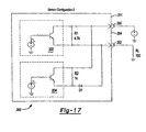
- Figure 17 is a schematic depicting an embodiment circuit for a two wire, dual sensor arrangement identified as Sensor Configuration 2;
- Figure 18 is a graph showing magnetic field density versus distance for Sensor Configuration 2;
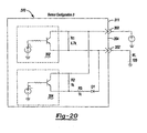
- Figure 20 is a schematic depicting an alternate embodiment circuit identified as Sensor Configuration 3;
- Figure 21 is a graph showing magnetic field density versus distance for Sensor Configuration 3.
- Figure 22 is a table depicting the output of the circuit of Figure 20 ;
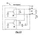
- Figure 23 is a schematic depicting an alternate embodiment circuit identified as Sensor Configuration 4.
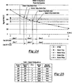
- Figure 24 is a graph showing magnetic field density versus distance for Sensor Configuration 4.
- Figure 25 is a table depicting the output of the circuit of Figure 23 ;
- Figure 26 is a schematic depicting an alternate embodiment circuit identified as Sensor Configuration 5;
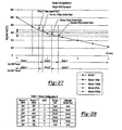
- Figure 27 is a graph showing magnetic field density versus distance for Sensor Configuration 5;
- Figure 28 is a table depicting the output of the circuit of Figure 26 ;
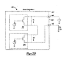
- Figure 29 is a schematic depicting another alternate embodiment circuit identified as Sensor Configuration 6;
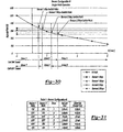
- Figure 30 is a graph showing magnetic field density versus distance for Sensor Configuration 6;
- Figure 31 is a table depicting the output of the circuit of Figure 29 ;
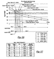
- Figure 32 is a graph showing magnetic field density versus distance for Sensor Configuration 6 where the Hall elements are programmed to have overlapping operational magnetic field ranges;
- Figure 33 is a table depicting the output of Sensor Configuration 6 having operational switch points as defined in Figure 32 ;
- Figure 34 is a graph showing magnetic field density versus distance for a circuit constructed according to Sensor Configuration 6 where the Hall effect sensors operate within dual magnetic fields;
- Figure 35 is a table depicting the output of the circuit according to Sensor Configuration 6 and Figure 34 ;
- Figure 36 is a graph showing magnetic field density versus distance for a circuit constructed according to Sensor Configuration 6 operating in dual magnetic fields where the operational magnetic field density ranges of the Hall effect sensors overlap;
- Figure 37 is a table depicting the output of the circuit according to Sensor Configuration 6 operating under the parameters defined by Figure 36 .
- the present invention is directed to an improved differential with a locking state detection system for a drivetrain of a motor vehicle.
- the differential of the present invention includes an actuator operable to place the differential in an "open” or “locked” condition.
- the detection system provides a signal indicating whether the differential is in the "open” or “locked” condition.
- the differential of the present invention may be utilized with a wide variety of driveline components and is not intended to be specifically limited to the particular application described herein.
- the actuator of the differential of the present invention may be used in conjunction with many types of differentials such as those having a bevel gear design or a parallel-axis helical design which may be of an open or limited-slip variety.
- a drivetrain 6 for an exemplary motor vehicle is shown to include an engine 8, a transmission 10, a transfer case 12, a forward propeller shaft 14 and a rearward propeller shaft 16.
- Rearward propeller shaft 16 provides torque to a rear axle assembly 18.
- Forward propeller shaft 14 provides torque from engine 8 to a pinion shaft 20 of a front axle assembly 22.
- Front axle assembly 22 includes an axle housing 24, a differential assembly 26 supported in axle housing 24 and a pair of axle shafts 28 and 30 respectively interconnected to left and right front wheels 32 and 34.
- Pinion shaft 20 has a pinion gear 36 fixed thereto which drives a ring gear 38 that is fixed to a differential case 40 of differential assembly 26.
- Differential case 40 is rotatably supported in axle housing 24 by a pair of laterally spaced bearings 41. Bearings 41 are retained by bearing caps 42 coupled to axle housing 24.
- a gearset 43 ( Figure 4 ) supported within differential case 40 transfers rotary power from differential case 40 to axle shafts 28 and 30, and facilitates relative rotation (i.e., differentiation) therebetween.
- rotary power from engine 8 is transmitted to axle shafts 28 and 30 for driving front wheels 32 and 34 via transmission 10, transfer case 12, forward propeller shaft 14, pinion shaft 20, differential case 40 and gearset 43.
- differential assembly 26 is depicted in a front-wheel drive application, the present invention is contemplated for use in differential assemblies installed in trailing axles, rear axles, transfer cases for use in four-wheel drive vehicles and/or any other known vehicular driveline application.
- Figures 4-8 depict differential assembly 26 to include differential case 40 and gearset 43.
- Gearset 43 includes a pair of pinion gears 44 rotatably supported on a cross shaft 45.
- First and second side gears 46 and 47 are drivingly interconnected to pinion gears 44 and axle shafts 28 and 30.
- Differential assembly 26 also includes an actuator and sensor assembly 48 operable to selectively couple first side gear 46 to differential case 40, thereby placing differential assembly 26 in a fully locked condition.
- a cap 49 is coupled to differential case 40 to define a pocket 50 for receipt of actuator and sensor assembly 48.
- Actuator and sensor assembly 48 includes a solenoid assembly 52, an actuating ring 54, a draw plate 56, a retainer 58 and a sensor assembly 59.
- Cap 49 includes a flange 60 coupled to a flange 62 of case 40.
- Flange 60 of cap 49 includes a recess 64 sized to receive a portion of solenoid assembly 52 during actuation.
- Cap 49 includes a pair of stepped bores 66 and 68 which define pocket 50.
- first bore 66 includes an annular surface 70 while second bore 68 includes an annular surface 72.
- First bore 66 includes an end face 74 radially inwardly extending from annular surface 70.
- An aperture 76 extends through the cap 49 and is in communication with second bore 68 where aperture 76 and second bore 68 are sized to receive a portion of the axle shaft.
- dogs 86 of actuating ring 54 are released from engagement with dogs 90 of side gear 46.
- dogs 86 engage dogs 90 to rotatably fix side gear 46 to differential case 40.
- Solenoid assembly 52 includes a metallic cup 94 and a wire coil 96.
- Wire coil 96 is positioned within cup 94 and secured thereto by an epoxy 98.
- Cup 94 includes an inner annular wall 100, an outer annular wall 102 and an end wall 104 interconnecting annular walls 100 and 102.
- Retainer 58 is a substantially disc-shaped member having an outer edge 106 mounted to end wall 104 of cup 94. A portion of retainer 58 is spaced apart from end wall 104 to define a slot 108.
- a target 126 includes a bracket 128, a magnet 130 and a fastener 132.
- Bracket 128 includes a first leg 134 having an aperture 136 extending therethrough. Fastener 132 extends through aperture 136 and is used to mount target 126 to bearing cap 42.
- Bracket 128 includes a second leg 138 positioned at a right angle to first leg 134. Second leg 138 is substantially planar and positioned substantially parallel to first face 112 of Hall element 110.
- Magnet 130 is a substantially cylindrical disk-shaped member mounted to second leg 138. Accordingly, magnet 130 includes an outer surface 139 (shown in Figure 7 ) positioned substantially parallel to first face 112.
- the sensor and magnet may be re-oriented 90 degrees to the orientation shown in the Figures. As such, the orientation of sensor and magnet shown in the drawings is merely exemplary and should not limit the scope of the invention.
- Draw plate 56 is positioned within slot 108 defined by retainer 58 and is coupled to actuating ring 54 via a plurality of fasteners 140.
- a washer 142 is positioned between cap 49 and actuating ring 54.
- washer 142 is constructed from a non-ferromagnetic material so as to reduce any tendency for actuating ring 54 to move toward end face 74 of metallic cap 49 instead of differential case 40 during energization of solenoid assembly 52.
- a bearing 144 supports cup 94 on an outer journal 146 of cap 49.
- Coil 96 is coupled to a controller 148 ( Figure 1 ) that operates to selectively energize and de-energize coil 96.
- a magnetic field is generated by current passing through coil 96.
- the magnetic field causes actuator and sensor assembly 48 to be drawn toward flange 60 of cap 49.
- solenoid assembly 52 enters recess 64
- dogs 86 of actuating ring 54 engage dogs 90 of side gear 46. Once the dogs are engaged, actuating ring 54 is in its engaged position and differential assembly 26 is in a fully locked condition as shown in Figure 8 .
- the Hall element 110 encompassed in sensor assembly 59 is spaced apart from outer surface 139 of magnet 130 by a distance "X.” At distance "X,” magnet 130 generates a predetermined magnetic field density.
- Sensor assembly 59 outputs a signal indicative of the axis) position of actuating ring 54. This signal is used by controller 148 as verification that differential assembly 26 is in a fully locked position.
- the axially moveable electromagnet provides a simplified design having a reduced number of components. Additionally, the present invention utilizes the entire differential case as the armature for the electromagnet. This allows a more efficient use of the available magnetic force. These features allow a designer to reduce the size of the electromagnet because the armature more efficiently utilizes the electromotive force supplied by the electromagnet. Such a compact design allows for minor modification of previously used components and packaging with a standard sized axle housing.
- differential assembly 26 To place differential assembly 26 in the open, unlocked condition, current is discontinued to coil 96. The magnetic field ceases to exist once current to coil 96 is stopped. At this time, compression in spring 85 causes actuator and sensor assembly 48 to axially translate and disengage dogs 86 from dogs 90. Accordingly, side gear 46 is no longer drivingly coupled to differential case 40, thereby placing differential assembly 26 in the open condition shown in Figure 7 .
- Hall element 1110 When differential assembly is in the open, unlocked condition, Hall element 1110 is positioned substantially closer to target 126 than when differential assembly 26 was in the locked position. Specifically, first face 112 is spaced apart from outer surface 139 of magnet 130 a distance "Y" when coil 96 is not energized.
- Sensor assembly 59 is configured to output a signal to controller 148 indicating that actuating ring 54 is at a position where dogs 86 are disengaged from dogs 90 and the differential is in an open condition. It should also be appreciated that actuation and deactuation times are very short due to the small number of moving components involved. Specifically, no relative ramping or actuation of other components is required to cause engagement or disengagement of dogs 86 and dogs 90.
- Electronic controller 148 controls the operation of actuator and sensor assembly 48.
- Electronic controller 148 is in receipt of data collected by a first speed sensors. 150 and a second speed sensor 152 as shown in Figure 1 .
- First speed sensor 150 provides data corresponding to the rotational speed of axle shaft 28.
- second speed sensor 152 measures the rotational speed of axle shaft 30 and outputs a signal to controller 148 indicative thereof.
- controller 148 will determine if an electrical signal is sent to coil 96.
- Controller 148 compares the measured or calculated parameters to predetermined values and outputs an electrical signal to place differential assembly 26 in the locked position only when specific conditions are met. As such, controller 148 assures that an "open” condition is maintained when events such as anti-lock braking occur. The "open” condition is verified by the signal output from sensor assembly 59. Limiting axis differentiation during anti-lock braking would possibly counteract the anti-look braking system. Other such situations may be programmed within controller 148.
- coil 162 does not axially translate nor rotate during any mode of operation of differential assembly 160.
- An axially moveable armature 168 is coupled to actuating ring 54.
- Armature 168 is shaped as an annular flat ring positioned proximate coil 162.
- Armature 168 and actuating ring 54 are drivingly coupled to differential case 40 and axially moveable relative to coil 162 and differential case 40.
- Armature 168 and actuating ring 54 are biased toward a disengaged, open differential, position shown in Figure 9 by a compression spring as previously described in relation to differential assembly 26.
- the power transmitting device of the present invention is not limited to such an application.
- the present invention may be used in rear drive axles, transaxles for front-wheel drive vehicles, transfer cases for use in four-drive vehicles and/or a number of other vehicular driveline application.
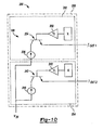
- Figure 10 depicts a circuit 198 having a second sensor assembly 200.
- Sensor assembly 200 includes a first Hall element 202, a second Hall element 204 and a body 206 encompassing both of the Hall elements.
- Sensor assembly 200 is shaped substantially similarly to sensor assembly 59.
- Sensor assembly 200 is positioned in communication with a differential assembly in a substantially similar manner to sensor assembly 59. Accordingly, the description relating to the mounting of sensor assembly 200 within the axle assembly will not be reiterated.
- Hall effect device Due to the nature of Hall effect devices, permanent magnets and the general environment in which sensor assembly 200 is required to function, a very large mechanical hysteresis is inherent in the system. Mechanical hysteresis in this instance is best described as the absolute distance the sensor assembly must travel in relation to the target magnet in order to change its output state.
- the Hall effect device switches state, or outputs a different signal, based on the Hall element being exposed to a changing magnetic field density.
- the Hall effect device may be configured to start switching at a predetermined magnetic field density described as its operating point (Bop) and the field density must change an amount equal to the inherent hysteresis (Bhys) of the Hall effect device in order to switch.
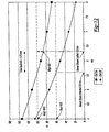
- Figure 11 is a graph showing magnetic field density versus distance for the first sensor assembly 59 shown in Figures 4-8 .
- permanent magnet 130 generates an exponentially decaying field density, measured in gauss versus the distance traveled in millimeters. For example, if Hall element 110 was programmed to switch at a Bop of 80 gauss and had a Bhys of 10 gauss, Hall element 110 would initiate a switch at 80 gauss and change its state at 70 gauss. Because a magnetic field is generated when coil 96 is energized, two distinct gauss curves are created. The upper curve depicts the field density present when the electro-magnet of solenoid assembly 52 is energized.
- the lower curve represents the magnetic field density generated by the permanent magnet alone when the coil 96 is not energized.
- a relatively large hysteresis is introduced into the system by operation of solenoid assembly 52.
- the magnitude of hysteresis introduced is by choice. It should be appreciated that the coil may be wired in the opposite polarity to reduce the relative gap between the gauss curves.
- sensor assembly 59 moves from a location where distance "Y” equals 4mm and distance "X” equal 8mm. Sensor assembly 59 does not output a signal indicating that the differential assembly is in the locked condition until sensor assembly 59 reaches a distance of 7.8mm of spacing between first face 112 and outer surface 139. During coil 96 deenergization, sensor assembly 59 does not output a signal indicating that the differential assembly is unlocked until the spacing between the Hall element and the permanent magnet is 4.8mm. As such, a total mechanical hysteresis of approximately 3mm exists with the single sensor arrangement Depending on the operational characteristics of the mechanical system including sensor assembly 59, this magnitude of hysteresis may or may be acceptable.
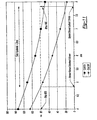
- Figure 12 is a graph showing magnetic field density versus distance for the second sensor assembly 200 shown in Figure 10 .
- Hall elements 202 and 204 of sensor assembly 200 are configured in accordance with Figures 10 and 12 .
- First Hall element 202 is set to have an operating point of 60 gauss while second Hall element 204 is set to have an operating point of 100 gauss.
- second Hall element 204 outputs a signal indicating that the differential assembly is in the locked condition once the magnetic field density reduces from 100 gauss to 90 gauss. This condition occurs when the spacing between second Hall element 204 and outer surface 139 of magnet 130 is approximately 6.3mm.
- first Hall element 202 outputs a signal indicative of an open differential condition once the magnetic field density changes from 50 to 60 gauss. This condition exists when first Hall element 202 is spaced from outer surface 139 a distance of approximately 5.6mm.
- first Hall element 202 is spaced from outer surface 139 a distance of approximately 5.6mm.
- the total mechanical hysteresis is now approximately 0.75mm when using two Hall elements with different operating points.
- the circuit 198 depicted in Figure 10 includes first Hall effect sensor 202 and second Hall effect sensor 204.
- First Hall effect sensor 202 is coupled in series with a differential gain amplifier 232.
- Differential gain amplifier 232 is coupled to the base of a current gain transistor 234.
- a constant current source 236 is supplied to the collector leg of current gain transistor 234.
- the emitter leg of current gain transistor 234 provides an output signal labeled as I OUT1 .
- second Hall effect sensor 204 is connected in series with a differential gain amplifier 240.
- Differential gain amplifier 240 is coupled to the base of a current gain transistor 242.
- Constant current source 236 is supplied to the collector leg of current gain transistor 242, The emitter leg of current gain transistor 242 provides an output signal labeled as I OUT2 .
- Controller 148 analyzes I OUT1 and I OUT2 to determine the operating mode of differentiation as being locked or unlocked. When both I OUT1 and I OUT2 are low or zero, controller 148 determines that the differential is operating in the locked mode. When I OUT1 and I OUT2 are both high or one, controller 148 determines that the differential is operating in the unlocked mode.
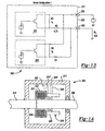
- Figure 13 depicts an alternate dual Hall sensor circuit 300 operable to output a signal indicative of the position of a moveable member within a power transmission device.
- Circuit 300 may be implemented in conjunction with the lockable differential assembly previously described. Furthermore, it is contemplated that circuit 300 may be used in conjunction with any number of power transmission subsystems that include an axially moveable member.
- Figure 14 shows a power transmission device 306 operable to selectively transfer torque from a first rotatable shaft 308 to a second rotatable shaft 310.
- the rotatable shafts are at least partially positioned within a housing 311 and are selectively drivingly interconnected by a clutch assembly 312.
- Clutch assembly 312 incudes a plurality of outer friction plates 314 slidably coupled to second shaft 310 and a plurality of inner friction plates 316 slidably coupled to shaft 308.
- Outer plates 314 are interleaved with inner plates 316.
- An actuator 318 is operable to axially displace an apply plate 320 such that a compressive force may be selectively applied to the clutch 312.
- the output torque of clutch 312 may be varied according to the input force generated by actuator 318.
- a sensor assembly 322 is mounted to housing 311.
- a target 324 is mounted to axially moveable apply plate 320.
- actuator 318 is operable to move apply plate 320 between at least three discrete positions. These positions are represented by target 324 being shown In solid line representation when apply plate 320 is at the first or returned position where no torque is transferred through clutch 312, a second position as denoted by target 324' in hidden line representation and a third position shown as target 324" also in hidden lines.
- actuator 318 moves apply plate 320 to take up axial clearance between outer plates 314 and inner plates 316 to place the clutch in a ready mode.
- clutch 312 transmits minimal torque, If any, between shaft 308 and shaft 310.
- a sensor circuit operable to output signals indicating when an axially moveable member such as apply plate 320 is at one of three locations.
- an axially moveable member such as apply plate 320 is at one of three locations.
- only two locations may need to be determined if the sensor arrangement is used in a device such as differential assemblies 26 or 160 because the axially moveable actuating ring 54 is typically in one of two locations.
- Actuating ring 54 is either in the fully returned position when the differential is in an open condition or the fully advanced position when the differential is in the locked condition.
- the circuit may output signals indicating that the target is in one of two different zones or that the target is located within one of three different zones of linear position.
- Figure 16 represents a state diagram defining the output of circuit 300 based on the operational states of sensor 302 and sensor 304.
- the table of Figure 16 identifies sensor 302 as sensor 1 and sensor 304 as sensor 2.
- Configuration 1 outputs 5 mA when the distance between the Hall effect sensors and the target is within zone 1 or 2.
- Both sensor 302 and sensor 304 are in the OFF state when the distance between the Hall effect sensors and the target is within zone 3.
- Iout equals 15 mA. Because the Hall effect sensors include inherent hysteresis, the distance at which the state of the sensor changes depends on whether the magnetic field density is increasing or decreasing.
- zones 1, 2 and 3 vary slightly depending on the direction of travel of the axially moveable member.
- sensor 2 switches from the ON state to the OFF state after the magnetic field density changes from Bop to Bhys.
- This change represents the spacing between the Hall effect sensor and the target as increasing at the point of transition from zone 2 to zone 3 as shown at approximately 1.75 mm.
- sensor 2 is shown to switch from the OFF to the ON state only after the magnetic field density increases from Bhys to Bop. This condition is shown to occur at approximately a 1.3 mm spacing as zone 3' is exited and zone 2' is entered.
- the beginning of zone 3 does not exactly correspond to the ending of zone 3'. This "tolerance" of the distance at which zone 2 ends and zone 3 starts should be accounted for in the logic of the controller utilizing the information output from circuit 300.
- Figure 19 includes another column entitled Alternate Sensor Iout which represents the output of circuit 360 if the operating points of sensors 1 and 2 were switched.
- Iout equals 5 mA when the spacing between the Hall effect sensors and the target is within zone 1.
- Iout equals 15 mA when the spacing between the sensors and the target is within zone 2.
- Iout equals 21 mA when the spacing between the sensors and the target is within zone 3.
- the versatility of the use of two programmable Hall effect sensors is illustrated by reviewing the Alternate Sensor Iout column and noting that the same circuit may be used to provide an indication when the spacing between Hall sensors is within one of two areas.
- Sensor Configuration 2 is easily programmed to provide a two position sensing arrangement or a three position sensing arrangement.
- Circuit 370 or Sensor Configuration 3 is substantially similar to Sensor Configurations 1 and 2 with minor changes to the circuit. The circuit modifications cause the magnitude of the output current levels to change. Furthermore, different sensor state combinations provide different outputs.
- the Sensor Iout column shows that 3 mA is output in zone 1 and zone 1' while 21 mA will be output when the spacing between the sensor and the target is within zone 2, zone 2', zone 3 or zone 3'.
- Figures 23-25 relate to Sensor Configuration 4 having a circuit 380.
- Figures 26-28 correspond to Sensor Configuration 5 having a circuit 390.
- Figures 29-31 depict Sensor Configuration 6 having a circuit 395.
- Sensor Configurations 4, 5 and 6 further illustrate the versatility of the present invention by constructing simple circuits using two Hall elements to output signals indicative of the position of an axially moveable component within a power transmission device.
- Figures 32 and 33 depict a method of adjusting the width of certain detection zones by modifying the operating switch point of one sensor relative to the other.
- the embodiments previously described included a first sensor having an operating range of magnetic field density defined by its operating point and its hysteresis switch point.
- the operating range of sensor 1 is spaced apart from the operating range of magnetic field density of sensor 2 because sensor 2 is purposefully configured with different operating and hysteresis switch points.
- Sensor Configuration 6 is shown to include the operating switch point of sensor 2 being programmed to lie within the operating range of magnetic field density defined by sensor 1.
- sensor 2 has an operating point (Bop) that is greater than the hysteresis switch point (Bhys) of sensor 1 but lower than the operating switch point (Bop) of sensor 1.
- Bop operating point
- the axial travel defined by zone 2 is greatly reduced.
- the distance traveled to exit zone 1, pass entirely through zone 2 and enter zone 3 is approximately .5 mm. Accordingly, the dual Hall sensor arrangement having overlapping operating ranges may be useful for an application where relatively small axial distances are traveled by the axially moveable member.
- Figures 34-37 illustrate that any one of the Sensor Configurations 1-6 may also be used in a dual field operation mode. These Figures also illustrate that the operating ranges of the Hall sensors may be overlapped or not overlapped in the dual field mode of operation as well as the single field mode of operation.
- the dual field operation mode was described in greater detail previously in reference to the lockable differential having an electromagnet with a coil operable to generate an electromagnetic field. However, in this embodiment the polarity of the permanent magnet and the electromagnet are positioned such that the magnetic field density at the sensors decreases when the electromagnet coil is on.
Landscapes
- Engineering & Computer Science (AREA)
- General Engineering & Computer Science (AREA)
- Mechanical Engineering (AREA)
- Physics & Mathematics (AREA)
- Electromagnetism (AREA)
- General Physics & Mathematics (AREA)
- Retarders (AREA)
- Arrangement And Mounting Of Devices That Control Transmission Of Motive Force (AREA)
- Measurement Of Length, Angles, Or The Like Using Electric Or Magnetic Means (AREA)
- Locating Faults (AREA)
- Push-Button Switches (AREA)
Abstract
Description
- The present invention generally relates to differentials for motor vehicles and, more particularly, to a locking differential with a locking state detection system.
- As is known, many motor vehicles are equipped with driveline systems including differential which function to drivingly interconnect an input shaft and a pair of output shafts. The differential functions to transmit drive torque to the output shafts while permitting speed differentiation between the output shafts.
- Conventional differentials include a pair of side gears fixed for rotation with the output shafts and two or more sets of meshed pinion gears mounted within a differential case. However, the conventional differential mechanism has a deficiency when a vehicle is operated on a slippery surface. When one wheel of the vehicle is on a surface halving a low coefficient of friction, most or all of the torque will be delivered to the slipping wheel. As a result, the vehicle often becomes immobilized.
- To overcome this problem, it is known to provide a mechanical differential having an additional mechanism that limits or selectively prevents differentiation of the speed between the output shafts. Typically, the mechanical device used to provide the limited-slip or non-slip function is a friction clutch. The friction clutch is a passive device which limits the differential speed between the output shafts only after a certain differential speed has been met. Additionally, such mechanical devices may not be selectively disengaged during operation of anti-lock braking systems or vehicle traction control systems. For example, four-wheel anti-lock braking systems may attempt to measure and control the rotational speed of each wheel independently. If a mechanical type limited slip differential is present, independent control of the speed of each wheel coupled to a differential is no longer possible. Accordingly, it would be desirable to provide an improved differential which may be actively controlled in conjunction with other control systems present on the vehicle. A detection system operable to determine the present state of operation of the differential may also be desirable.
EP-A-1 628 029 , which is admissible as prior art only under Article 54(3) EPC, discloses an over-running clutch comprising a sensor that detects the proximity of an actuation disc relative to the inner surface of a case end, and sends a corresponding signal to indicate that the clutch is engaged or disengaged. The sensor comprises a pair of Hall effect sensors spaced apart from one another and mounted within an electromagnetic coil. The sensors are aligned with opposite ends of one of the slots formed within the case end. The sensors are spaced by at least the angular distance between opposite ends of one of the slots in the case end. The sensors are wired in parallel so that at least one of the sensors is triggered at any time to provide a continuous signal even when gaps in the axial lobes and the magnets are in close proximity to the other Hall effect sensor. The outputs of the Hall effect sensors can be tied together to a common output. A "pull-up" resistor is used to bring the "high" signal up to the supply voltage. This circuit layout provides a fail safe normal "high" signal for the disengaged position, and results in a "low" signal whenever one or both of the Hall effect sensors is activated.
EP-A-1 726 851 , which is also only admissible as prior art under Article 54(3) EPC, discloses a power transmitting device comprising a housing, a case rotatably positioned within the housing and a pair of pinion gears and a pair of side gears rotatably supported in the case. The device further comprises an electrically operable coupling including an electromagnet and an axially moveable member operable to drivingly connect one of the side gears with the case. A sensor is coupled to one of the housing, the case and the axially moveable member, and is operable to output a signal indicative of the position of the axially moveable member. This sensor is a Hall effect type sensor operable to output a signal indicative of the proximity of a target to the sensor. - According to a first aspect of the present invention there is provided the axle assembly of
claim 1.
According to a second aspect of the present invention there is provided the method of claim 14.
Embodiments of apparatus in accordance with the present invention will now be described, by way of example only, with reference to the accompanying drawings. - The present invention will become more fully understood from the detailed description and the accompanying drawings, wherein:
-
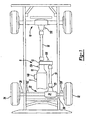
Figure 1 is a schematic view of an exemplary motor vehicle drivetrain including a differential assembly; -
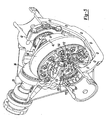
Figure 2 is a fragmentary perspective view of a front driving axle; -
Figure 3 is a fragmentary perspective view of the front driving axle; -
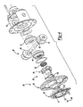
Figure 4 is an exploded perspective view of a differential assembly; -
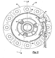
Figure 5 is an end view of the differential assembly; -
Figure 6 is a orass-sectional side view of the differential assembly taken along line 6-6 inFigure 5 ; -
Figure 7 is a fragmentary side view of the differential assembly showing the actuating ring in a position disengaged from the side gear; -
Figure 8 is a fragmentary side view of the differential assembly showing the actuating ring in a position drivingly engaged with the side gear; -
Figure 9 is a fragmentary perspective of a second differential assembly; -
Figure 10 is a schematic depicting a circuit including a second sensor assembly; -
Figure 11 is a graph showing magnetic field density vs. distance for a first sensor assembly; -
Figure 12 is a graph showing magnetic field density vs. distance for a second sensor assembly; -
Figure 13 is a schematic depicting a circuit for a two wire, dual sensor arrangement identified asSensor Configuration 1; -
Figure 14 is a schematic diagram depicting an alternate power transmission device; -
Figure 15 is a graph showing magnetic field density versus distance for a dual Hall sensor arrangement operating in a single magnetic field perSensor Configuration 1; -
Figure 16 is a table depicting the output of the circuit ofFigure 13 based on the operational state of the sensors: -
Figure 17 is a schematic depicting an embodiment circuit for a two wire, dual sensor arrangement identified asSensor Configuration 2; -
Figure 18 is a graph showing magnetic field density versus distance forSensor Configuration 2; -
Figure 19 is a table depicting the output of the circuit ofFigure 17 ; -
Figure 20 is a schematic depicting an alternate embodiment circuit identified asSensor Configuration 3; -
Figure 21 is a graph showing magnetic field density versus distance forSensor Configuration 3; -
Figure 22 is a table depicting the output of the circuit ofFigure 20 ; -
Figure 23 is a schematic depicting an alternate embodiment circuit identified as Sensor Configuration 4; -
Figure 24 is a graph showing magnetic field density versus distance for Sensor Configuration 4; -
Figure 25 is a table depicting the output of the circuit ofFigure 23 ; -
Figure 26 is a schematic depicting an alternate embodiment circuit identified asSensor Configuration 5; -
Figure 27 is a graph showing magnetic field density versus distance forSensor Configuration 5; -
Figure 28 is a table depicting the output of the circuit ofFigure 26 ; -
Figure 29 is a schematic depicting another alternate embodiment circuit identified asSensor Configuration 6; -
Figure 30 is a graph showing magnetic field density versus distance forSensor Configuration 6; -
Figure 31 is a table depicting the output of the circuit ofFigure 29 ; -
Figure 32 is a graph showing magnetic field density versus distance forSensor Configuration 6 where the Hall elements are programmed to have overlapping operational magnetic field ranges; -
Figure 33 is a table depicting the output ofSensor Configuration 6 having operational switch points as defined inFigure 32 ; -
Figure 34 is a graph showing magnetic field density versus distance for a circuit constructed according toSensor Configuration 6 where the Hall effect sensors operate within dual magnetic fields; -
Figure 35 is a table depicting the output of the circuit according toSensor Configuration 6 andFigure 34 ; -
Figure 36 is a graph showing magnetic field density versus distance for a circuit constructed according toSensor Configuration 6 operating in dual magnetic fields where the operational magnetic field density ranges of the Hall effect sensors overlap; and -
Figure 37 is a table depicting the output of the circuit according toSensor Configuration 6 operating under the parameters defined byFigure 36 . - The present invention is directed to an improved differential with a locking state detection system for a drivetrain of a motor vehicle. The differential of the present invention includes an actuator operable to place the differential in an "open" or "locked" condition. The detection system provides a signal indicating whether the differential is in the "open" or "locked" condition. It should be appreciated that the differential of the present invention may be utilized with a wide variety of driveline components and is not intended to be specifically limited to the particular application described herein. In addition, the actuator of the differential of the present invention may be used in conjunction with many types of differentials such as those having a bevel gear design or a parallel-axis helical design which may be of an open or limited-slip variety.
- With reference to
Figures 1-3 , adrivetrain 6 for an exemplary motor vehicle is shown to include anengine 8, atransmission 10, a transfer case 12, a forward propeller shaft 14 and arearward propeller shaft 16.Rearward propeller shaft 16 provides torque to arear axle assembly 18. Forward propeller shaft 14 provides torque fromengine 8 to apinion shaft 20 of afront axle assembly 22.Front axle assembly 22 includes anaxle housing 24, adifferential assembly 26 supported inaxle housing 24 and a pair ofaxle shafts front wheels -
Pinion shaft 20 has apinion gear 36 fixed thereto which drives aring gear 38 that is fixed to adifferential case 40 ofdifferential assembly 26.Differential case 40 is rotatably supported inaxle housing 24 by a pair of laterally spaced bearings 41. Bearings 41 are retained by bearingcaps 42 coupled toaxle housing 24. A gearset 43 (Figure 4 ) supported withindifferential case 40 transfers rotary power fromdifferential case 40 toaxle shafts engine 8 is transmitted toaxle shafts front wheels transmission 10, transfer case 12, forward propeller shaft 14,pinion shaft 20,differential case 40 and gearset 43. Whiledifferential assembly 26 is depicted in a front-wheel drive application, the present invention is contemplated for use in differential assemblies installed in trailing axles, rear axles, transfer cases for use in four-wheel drive vehicles and/or any other known vehicular driveline application. -
Figures 4-8 depictdifferential assembly 26 to includedifferential case 40 and gearset 43. Gearset 43 includes a pair of pinion gears 44 rotatably supported on across shaft 45. First and second side gears 46 and 47 are drivingly interconnected to pinion gears 44 andaxle shafts Differential assembly 26 also includes an actuator andsensor assembly 48 operable to selectively couplefirst side gear 46 todifferential case 40, thereby placingdifferential assembly 26 in a fully locked condition. - A
cap 49 is coupled todifferential case 40 to define a pocket 50 for receipt of actuator andsensor assembly 48. Actuator andsensor assembly 48 includes asolenoid assembly 52, anactuating ring 54, adraw plate 56, aretainer 58 and asensor assembly 59.Cap 49 includes aflange 60 coupled to aflange 62 ofcase 40.Flange 60 ofcap 49 includes arecess 64 sized to receive a portion ofsolenoid assembly 52 during actuation.Cap 49 includes a pair of stepped bores 66 and 68 which define pocket 50. Specifically, first bore 66 includes an annular surface 70 whilesecond bore 68 includes anannular surface 72. First bore 66 includes anend face 74 radially inwardly extending from annular surface 70. Anaperture 76 extends through thecap 49 and is in communication withsecond bore 68 whereaperture 76 and second bore 68 are sized to receive a portion of the axle shaft. -
Actuating ring 54 includes a generally hollowcylindrical body 78 having anannular recess 80 formed at one end.Side gear 46 includes a similarly sized annular recess 82 formed on an outboard face 84. Acompression spring 85 is positioned between actuatingring 54 andside gear 46 withinannular recesses 80 and 82. A plurality of axially extendingdogs 86 protrude from an end face 88 of actuatingring 54. A corresponding plurality ofdogs 90 axially extend from outboard face 84 ofside gear 46.Actuating ring 54 is moveable from a disengaged position as shown inFigures 6 and7 to an engaged position shown inFigure 8 . In the disengaged position, dogs 86 of actuatingring 54 are released from engagement withdogs 90 ofside gear 46. In contrast, when actuatingring 54 is moved to its engaged position, dogs 86 engagedogs 90 to rotatably fixside gear 46 todifferential case 40. -
Solenoid assembly 52 includes ametallic cup 94 and a wire coil 96. Wire coil 96 is positioned withincup 94 and secured thereto by anepoxy 98.Cup 94 includes an innerannular wall 100, an outerannular wall 102 and anend wall 104 interconnectingannular walls Retainer 58 is a substantially disc-shaped member having anouter edge 106 mounted to endwall 104 ofcup 94. A portion ofretainer 58 is spaced apart fromend wall 104 to define aslot 108. -
Retainer 58 includes a pair of axially extendingtabs 109 positioned proximate to bearingcap 42.Tabs 109 restrict rotation ofretainer 58 relative toaxle housing 24.Sensor assembly 59 is mounted toretainer 58.Sensor assembly 59 includes aHall element 110 having a substantially rectangular body.Hall element 110 includes afirst face 112 extending substantially perpendicularly to the axis of rotation ofaxle shafts Sensor assembly 59 also includes a pair ofwires 114 extending fromHall element 110 that end atterminals 116 mounted within aconnector 118.Connector 118 includes abody 120 extending through anaperture 122 formed inaxle housing 24. The ends of the wire on wire coil 96 terminate atterminals 124 mounted withinconnector 118. In this manner, electrical connection tosolenoid assembly 52 andsensor assembly 59 may be made from outside ofaxle housing 24. - A
target 126 includes abracket 128, amagnet 130 and afastener 132.Bracket 128 includes afirst leg 134 having anaperture 136 extending therethrough.Fastener 132 extends throughaperture 136 and is used to mounttarget 126 to bearingcap 42.Bracket 128 includes asecond leg 138 positioned at a right angle tofirst leg 134.Second leg 138 is substantially planar and positioned substantially parallel tofirst face 112 ofHall element 110.Magnet 130 is a substantially cylindrical disk-shaped member mounted tosecond leg 138. Accordingly,magnet 130 includes an outer surface 139 (shown inFigure 7 ) positioned substantially parallel tofirst face 112. One skilled in the art will appreciate that the sensor and magnet may be re-oriented 90 degrees to the orientation shown in the Figures. As such, the orientation of sensor and magnet shown in the drawings is merely exemplary and should not limit the scope of the invention. - Draw
plate 56 is positioned withinslot 108 defined byretainer 58 and is coupled to actuatingring 54 via a plurality offasteners 140. Awasher 142 is positioned betweencap 49 andactuating ring 54. Preferably,washer 142 is constructed from a non-ferromagnetic material so as to reduce any tendency for actuatingring 54 to move toward end face 74 ofmetallic cap 49 instead ofdifferential case 40 during energization ofsolenoid assembly 52. Abearing 144 supportscup 94 on anouter journal 146 ofcap 49. - Coil 96 is coupled to a controller 148 (
Figure 1 ) that operates to selectively energize and de-energize coil 96. During coil energization, a magnetic field is generated by current passing through coil 96. The magnetic field causes actuator andsensor assembly 48 to be drawn towardflange 60 ofcap 49. Assolenoid assembly 52 entersrecess 64,dogs 86 of actuatingring 54 engagedogs 90 ofside gear 46. Once the dogs are engaged,actuating ring 54 is in its engaged position anddifferential assembly 26 is in a fully locked condition as shown inFigure 8 . In the fully locked position, theHall element 110 encompassed insensor assembly 59 is spaced apart fromouter surface 139 ofmagnet 130 by a distance "X." At distance "X,"magnet 130 generates a predetermined magnetic field density.Sensor assembly 59 outputs a signal indicative of the axis) position of actuatingring 54. This signal is used bycontroller 148 as verification thatdifferential assembly 26 is in a fully locked position. - One skilled in the art will appreciate that the axially moveable electromagnet provides a simplified design having a reduced number of components. Additionally, the present invention utilizes the entire differential case as the armature for the electromagnet. This allows a more efficient use of the available magnetic force. These features allow a designer to reduce the size of the electromagnet because the armature more efficiently utilizes the electromotive force supplied by the electromagnet. Such a compact design allows for minor modification of previously used components and packaging with a standard sized axle housing.
- To place
differential assembly 26 in the open, unlocked condition, current is discontinued to coil 96. The magnetic field ceases to exist once current to coil 96 is stopped. At this time, compression inspring 85 causes actuator andsensor assembly 48 to axially translate and disengagedogs 86 fromdogs 90. Accordingly,side gear 46 is no longer drivingly coupled todifferential case 40, thereby placingdifferential assembly 26 in the open condition shown inFigure 7 . When differential assembly is in the open, unlocked condition, Hall element 1110 is positioned substantially closer to target 126 than whendifferential assembly 26 was in the locked position. Specifically,first face 112 is spaced apart fromouter surface 139 of magnet 130 a distance "Y" when coil 96 is not energized. At distance "Y," the magnetic field density generated bymagnet 130 is significantly greater than the field density at distance "X."Sensor assembly 59 is configured to output a signal tocontroller 148 indicating that actuatingring 54 is at a position where dogs 86 are disengaged fromdogs 90 and the differential is in an open condition. It should also be appreciated that actuation and deactuation times are very short due to the small number of moving components involved. Specifically, no relative ramping or actuation of other components is required to cause engagement or disengagement ofdogs 86 and dogs 90. -
Electronic controller 148 controls the operation of actuator andsensor assembly 48.Electronic controller 148 is in receipt of data collected by a first speed sensors. 150 and asecond speed sensor 152 as shown inFigure 1 .First speed sensor 150 provides data corresponding to the rotational speed ofaxle shaft 28. Similarly,second speed sensor 152 measures the rotational speed ofaxle shaft 30 and outputs a signal tocontroller 148 indicative thereof. Depending on the data collected at any number of vehicle sensors such as agear position sensor 154, avehicle speed sensor 156, a transfer case range position sensor or abrake sensor 158 as shown inFigure 1 ,controller 148 will determine if an electrical signal is sent to coil 96.Controller 148 compares the measured or calculated parameters to predetermined values and outputs an electrical signal to placedifferential assembly 26 in the locked position only when specific conditions are met. As such,controller 148 assures that an "open" condition is maintained when events such as anti-lock braking occur. The "open" condition is verified by the signal output fromsensor assembly 59. Limiting axis differentiation during anti-lock braking would possibly counteract the anti-look braking system. Other such situations may be programmed withincontroller 148. -
Figure 9 depicts a second differential assembly 180.Differential assembly 160 is substantially similar todifferential assembly 26. For clarity, like elements have been identified with previously introduced reference numerals.Differential assembly 160 differs fromdifferential assembly 26 in that acoil 162 is rotatably mounted ondifferential case 40 in a fixed axial position. Ananti-rotation bracket 164 interconnects acup 166 with the axle housing 24 (Figure 3 ) to restrictcoil 162 from rotation. A bearing 167 rotatably supportscup 166 to allow thedifferential case 40 to rotate relative to thecoil 162 during operation of the differential assembly. - Through the use of a
stationary coil 162, power supply and sensor wire routing complexities may be reduced because the wires no longer need to account for axial movement of the coil. As such,coil 162 does not axially translate nor rotate during any mode of operation ofdifferential assembly 160. An axiallymoveable armature 168 is coupled to actuatingring 54.Armature 168 is shaped as an annular flat ring positionedproximate coil 162.Armature 168 and actuatingring 54 are drivingly coupled todifferential case 40 and axially moveable relative tocoil 162 anddifferential case 40.Armature 168 and actuatingring 54 are biased toward a disengaged, open differential, position shown inFigure 9 by a compression spring as previously described in relation todifferential assembly 26. - To place
differential assembly 160 in a locked condition,coil 162 is energized to generate a magnetic field.Armature 168 is constructed from a ferromagnetic material. Accordingly,armature 168 and actuatingring 54 are axially displaced to drivingly engage actuatingring 54 withside gear 46 to placedifferential assembly 160 in a locked condition. - While a front drive axle assembly has been described in detail, it should be appreciated that the power transmitting device of the present invention is not limited to such an application. Specifically, the present invention may be used in rear drive axles, transaxles for front-wheel drive vehicles, transfer cases for use in four-drive vehicles and/or a number of other vehicular driveline application.
-
Figure 10 depicts acircuit 198 having asecond sensor assembly 200.Sensor assembly 200 includes afirst Hall element 202, asecond Hall element 204 and a body 206 encompassing both of the Hall elements.Sensor assembly 200 is shaped substantially similarly tosensor assembly 59.Sensor assembly 200 is positioned in communication with a differential assembly in a substantially similar manner tosensor assembly 59. Accordingly, the description relating to the mounting ofsensor assembly 200 within the axle assembly will not be reiterated. - Due to the nature of Hall effect devices, permanent magnets and the general environment in which
sensor assembly 200 is required to function, a very large mechanical hysteresis is inherent in the system. Mechanical hysteresis in this instance is best described as the absolute distance the sensor assembly must travel in relation to the target magnet in order to change its output state. The Hall effect device switches state, or outputs a different signal, based on the Hall element being exposed to a changing magnetic field density. The Hall effect device may be configured to start switching at a predetermined magnetic field density described as its operating point (Bop) and the field density must change an amount equal to the inherent hysteresis (Bhys) of the Hall effect device in order to switch. -
Figure 11 is a graph showing magnetic field density versus distance for thefirst sensor assembly 59 shown inFigures 4-8 . As shown inFigure 11 ,permanent magnet 130 generates an exponentially decaying field density, measured in gauss versus the distance traveled in millimeters. For example, ifHall element 110 was programmed to switch at a Bop of 80 gauss and had a Bhys of 10 gauss,Hall element 110 would initiate a switch at 80 gauss and change its state at 70 gauss. Because a magnetic field is generated when coil 96 is energized, two distinct gauss curves are created. The upper curve depicts the field density present when the electro-magnet ofsolenoid assembly 52 is energized. The lower curve represents the magnetic field density generated by the permanent magnet alone when the coil 96 is not energized. As shown, a relatively large hysteresis is introduced into the system by operation ofsolenoid assembly 52. The magnitude of hysteresis introduced is by choice. It should be appreciated that the coil may be wired in the opposite polarity to reduce the relative gap between the gauss curves. - In the arrangement depicted in
Figure 11 ,sensor assembly 59 moves from a location where distance "Y" equals 4mm and distance "X" equal 8mm.Sensor assembly 59 does not output a signal indicating that the differential assembly is in the locked condition untilsensor assembly 59 reaches a distance of 7.8mm of spacing betweenfirst face 112 andouter surface 139. During coil 96 deenergization,sensor assembly 59 does not output a signal indicating that the differential assembly is unlocked until the spacing between the Hall element and the permanent magnet is 4.8mm. As such, a total mechanical hysteresis of approximately 3mm exists with the single sensor arrangement Depending on the operational characteristics of the mechanical system includingsensor assembly 59, this magnitude of hysteresis may or may be acceptable. -
Figure 12 is a graph showing magnetic field density versus distance for thesecond sensor assembly 200 shown inFigure 10 . To reduce the magnitude of mechanical hysteresis,Hall elements sensor assembly 200 are configured in accordance withFigures 10 and12 .First Hall element 202 is set to have an operating point of 60 gauss whilesecond Hall element 204 is set to have an operating point of 100 gauss. During operation,second Hall element 204 outputs a signal indicating that the differential assembly is in the locked condition once the magnetic field density reduces from 100 gauss to 90 gauss. This condition occurs when the spacing betweensecond Hall element 204 andouter surface 139 ofmagnet 130 is approximately 6.3mm. At electromagnet deenergization,first Hall element 202 outputs a signal indicative of an open differential condition once the magnetic field density changes from 50 to 60 gauss. This condition exists whenfirst Hall element 202 is spaced from outer surface 139 a distance of approximately 5.6mm. One skilled in the art will appreciate that the total mechanical hysteresis is now approximately 0.75mm when using two Hall elements with different operating points. - The
circuit 198 depicted inFigure 10 includes firstHall effect sensor 202 and secondHall effect sensor 204. FirstHall effect sensor 202 is coupled in series with adifferential gain amplifier 232.Differential gain amplifier 232 is coupled to the base of acurrent gain transistor 234. A constantcurrent source 236 is supplied to the collector leg ofcurrent gain transistor 234. The emitter leg ofcurrent gain transistor 234 provides an output signal labeled as IOUT1. - In similar fashion, second
Hall effect sensor 204 is connected in series with adifferential gain amplifier 240.Differential gain amplifier 240 is coupled to the base of acurrent gain transistor 242. Constantcurrent source 236 is supplied to the collector leg ofcurrent gain transistor 242, The emitter leg ofcurrent gain transistor 242 provides an output signal labeled as IOUT2. Controller 148 analyzes IOUT1 and IOUT2 to determine the operating mode of differentiation as being locked or unlocked. When both IOUT1 and IOUT2 are low or zero,controller 148 determines that the differential is operating in the locked mode. When IOUT1 and IOUT2 are both high or one,controller 148 determines that the differential is operating in the unlocked mode. -
Figure 13 depicts an alternate dualHall sensor circuit 300 operable to output a signal indicative of the position of a moveable member within a power transmission device.Circuit 300 may be implemented in conjunction with the lockable differential assembly previously described. Furthermore, it is contemplated thatcircuit 300 may be used in conjunction with any number of power transmission subsystems that include an axially moveable member. - For example,
Figure 14 shows apower transmission device 306 operable to selectively transfer torque from a firstrotatable shaft 308 to a secondrotatable shaft 310. The rotatable shafts are at least partially positioned within ahousing 311 and are selectively drivingly interconnected by aclutch assembly 312.Clutch assembly 312 incudes a plurality ofouter friction plates 314 slidably coupled tosecond shaft 310 and a plurality ofinner friction plates 316 slidably coupled toshaft 308.Outer plates 314 are interleaved withinner plates 316. Anactuator 318 is operable to axially displace an applyplate 320 such that a compressive force may be selectively applied to the clutch 312. The output torque ofclutch 312 may be varied according to the input force generated byactuator 318. - A
sensor assembly 322 is mounted tohousing 311. Atarget 324 is mounted to axially moveable applyplate 320. In operation,actuator 318 is operable to move applyplate 320 between at least three discrete positions. These positions are represented bytarget 324 being shown In solid line representation when applyplate 320 is at the first or returned position where no torque is transferred throughclutch 312, a second position as denoted by target 324' in hidden line representation and a third position shown astarget 324" also in hidden lines. At position 324',actuator 318 moves applyplate 320 to take up axial clearance betweenouter plates 314 andinner plates 316 to place the clutch in a ready mode. At this position, clutch 312 transmits minimal torque, If any, betweenshaft 308 andshaft 310. However, very slight movement of applyplate 320 toward the clutch 312 will cause the clutch to generate a significant amount of torque in a relatively short period of time. In this manner, torque delivery will not be delayed due to the actuator having to travel large distances to account for the clearance between the actuator plate and the friction plates of the clutch. - When the target is at
position 324",actuator 318 has driven applyplate 320 in full engagement withclutch 312 and torque is being transferred through the clutch. Accordingly, it may be beneficial to construct a sensor circuit operable to output signals indicating when an axially moveable member such as applyplate 320 is at one of three locations. Alternatively, only two locations may need to be determined if the sensor arrangement is used in a device such asdifferential assemblies moveable actuating ring 54 is typically in one of two locations.Actuating ring 54 is either in the fully returned position when the differential is in an open condition or the fully advanced position when the differential is in the locked condition. Various circuit embodiments and sensor configurations will be described hereinafter. Depending on the sensor configuration, the circuit may output signals indicating that the target is in one of two different zones or that the target is located within one of three different zones of linear position. - Referring again to
Figure 13 ,circuit 300 depicts aSensor Configuration 1.Figures 15 and 16 also relate toSensor Configuration 1.Circuit 300 includes afirst Hall sensor 302, asecond Hall sensor 304, a number of resistors, R1, R2 and R3 as well as a diode D1 electrically interconnected as shown. These resistors and the diode are located within the housing of the power transmission device. Afirst pin 350 and asecond pin 352 exit the housing at abulkhead connector 354.First pin 350 is connected to a DC power source whilesecond pin 352 is connected to a load resistor RL. Load resistor RL functions as a current sensing element and provides an output signal Iout. One skilled in the art will appreciate that minimizing the number of wires, terminals, pins or other electrical connectors passing through the wall of the housing is beneficial. For example, the impact on the housing structural integrity is minimized and the aperture extending through the housing may be more easily sealed if the size of the aperture is minimized. -
Figure 16 represents a state diagram defining the output ofcircuit 300 based on the operational states ofsensor 302 andsensor 304. The table ofFigure 16 identifiessensor 302 assensor 1 andsensor 304 assensor 2. As is noted by reviewing the column labeled Sensor Iout,Configuration 1outputs 5 mA when the distance between the Hall effect sensors and the target is withinzone sensor 302 andsensor 304 are in the OFF state when the distance between the Hall effect sensors and the target is withinzone 3. When both sensors are in the OFF state, Iout equals 15 mA. Because the Hall effect sensors include inherent hysteresis, the distance at which the state of the sensor changes depends on whether the magnetic field density is increasing or decreasing. Accordingly,zones sensor 2 switches from the ON state to the OFF state after the magnetic field density changes from Bop to Bhys. This change represents the spacing between the Hall effect sensor and the target as increasing at the point of transition fromzone 2 tozone 3 as shown at approximately 1.75 mm. If the Hall effect sensor is exposed to an increasing magnetic field density,sensor 2 is shown to switch from the OFF to the ON state only after the magnetic field density increases from Bhys to Bop. This condition is shown to occur at approximately a 1.3 mm spacing as zone 3' is exited andzone 2' is entered. As is illustrated by the graph, the beginning ofzone 3 does not exactly correspond to the ending of zone 3'. This "tolerance" of the distance at whichzone 2 ends andzone 3 starts should be accounted for in the logic of the controller utilizing the information output fromcircuit 300. -
Figures 17-19 depict anelectrical circuit 360 substantially similar tocircuit 300 but having a different topology, identified asSensor Configuration 2.Circuit 360 includesfirst sensor 302 andsecond sensor 304 wired in communication with resistors R1 and R2 as well as diode D1. The resistance value for R1 has been changed and R3 has been removed.First pin 350 andsecond pin 352 exit the housing of the power transmission device as previously described.Pin 350 is coupled to a DC power source and pin 352 is coupled to a current sensing load resistor RL.Figure 19 includes a column labeled Sensor Iout which represents the output of thecircuit 360 wheresensor 1 has a Bop greater than the Bop ofsensor 2.Figure 19 includes another column entitled Alternate Sensor Iout which represents the output ofcircuit 360 if the operating points ofsensors sensor 1 andsensor 2 according to the column labeled Sensor Iout. Specifically, Iout equals 5 mA when the spacing between the Hall effect sensors and the target is withinzone 1. Iout equals 15 mA when the spacing between the sensors and the target is withinzone 2. Iout equals 21 mA when the spacing between the sensors and the target is withinzone 3. The versatility of the use of two programmable Hall effect sensors is illustrated by reviewing the Alternate Sensor Iout column and noting that the same circuit may be used to provide an indication when the spacing between Hall sensors is within one of two areas. Different signals are output if the spacing lies withinzone 1 or withinzones sensor 1 andsensor 2 are both in the ON state. Otherwise, if one or both of the sensors are in the OFF state, 21 mA is output. Therefore,Sensor Configuration 2 is easily programmed to provide a two position sensing arrangement or a three position sensing arrangement. - Another
circuit configuration 370 is represented byFigures 20-22 .Circuit 370 orSensor Configuration 3 is substantially similar toSensor Configurations zone 1 and zone 1' while 21 mA will be output when the spacing between the sensor and the target is withinzone 2,zone 2',zone 3 or zone 3'. -
Figures 23-25 relate to Sensor Configuration 4 having acircuit 380.Figures 26-28 correspond toSensor Configuration 5 having acircuit 390.Figures 29-31 depictSensor Configuration 6 having acircuit 395. Each of these configurations is substantially similar to Sensor Configurations 1-3 previously described in detail. As such, like elements will retain their previously introduced reference numerals.Sensor Configurations -
Figures 32 and 33 depict a method of adjusting the width of certain detection zones by modifying the operating switch point of one sensor relative to the other. The embodiments previously described included a first sensor having an operating range of magnetic field density defined by its operating point and its hysteresis switch point. The operating range ofsensor 1 is spaced apart from the operating range of magnetic field density ofsensor 2 becausesensor 2 is purposefully configured with different operating and hysteresis switch points. In the embodiment depicted inFigure 32 ,Sensor Configuration 6 is shown to include the operating switch point ofsensor 2 being programmed to lie within the operating range of magnetic field density defined bysensor 1. Specifically,sensor 2 has an operating point (Bop) that is greater than the hysteresis switch point (Bhys) ofsensor 1 but lower than the operating switch point (Bop) ofsensor 1. By setting the operating switch points of the two Hall effect sensors relatively closely together, the axial travel defined byzone 2 is greatly reduced. As depicted inFigures 32 and 33 , the distance traveled to exitzone 1, pass entirely throughzone 2 and enterzone 3 is approximately .5 mm. Accordingly, the dual Hall sensor arrangement having overlapping operating ranges may be useful for an application where relatively small axial distances are traveled by the axially moveable member. -
Figures 34-37 illustrate that any one of the Sensor Configurations 1-6 may also be used in a dual field operation mode. These Figures also illustrate that the operating ranges of the Hall sensors may be overlapped or not overlapped in the dual field mode of operation as well as the single field mode of operation. The dual field operation mode was described in greater detail previously in reference to the lockable differential having an electromagnet with a coil operable to generate an electromagnetic field. However, in this embodiment the polarity of the permanent magnet and the electromagnet are positioned such that the magnetic field density at the sensors decreases when the electromagnet coil is on.
Claims (15)
- An axle assembly (18, 22) comprising:a housing (24, 311);a first shaft (28, 308) rotatably positioned in the housing (24, 311);a second shaft (30, 310) rotatably positioned in the housing (24, 311);a clutch (26, 160, 306) positioned in the housing, the clutch being operable to selectively couple the first shaft (28, 308) to the second shaft (30, 310), the clutch (26, 160, 306) being operable in a first mode in which the first shaft (28, 308) co-rotates with the second shaft (30, 310), the clutch (26, 160, 306) also being operable in a second mode that is different from the first mode;an actuator (52, 318) having a linearly movable member (54, 320) movable between a first position, which causes the clutch (26, 160, 306) to operate in the first mode, and a second position, that causes the clutch (26, 160, 306) to operate in the second mode, the actuator (52, 318) being operable to move the linearly movable member (54, 320) between the first and second positions; anda sensor circuit (360, 380, 390, 395) positioned within the housing (24, 311), the sensor circuit (360,380) including two electrically interconnected Hall effect devices (302, 304) configured to sense the linear position of the movable member (54,320) and configured to produce an output signal indicative of a position of the movable member (54, 320), the output signal having a first value when the movable member (54, 320) is in the first position, the output signal having a second value when the movable member (54, 320) is in the second position and the output signal having a third value when the movable member (54, 320) is in a position that is between the first and second positions.
- The axle assembly (18, 22) of claim 1 wherein the Hall effect devices (302, 304) are electrically coupled in parallel.
- The axle assembly (18, 22) of claim 1 wherein the Hall effect devices (302, 3 04) are electrically coupled in series.
- The axle assembly (18, 22) of any one of the preceding claims wherein a first one of the Hall effect devices (302, 304) is associated with a first operating range of magnetic field density between switching states and a second one of the Hall effect devices (302, 304) is associated with a second operating range of magnetic field density between switching states and wherein the first operating range overlaps the second operating range.
- The axle assembly (18, 22) of any one of claims 1 to 3 wherein a first one of the Hall effect devices (302, 304) is associated with a first operating range of magnetic field density between switching states and a second one of the Hall effect devices (302, 304) is associated with a second operating range of magnetic field density between switching states and wherein the first operating range does not overlap the second operating range.
- The axle assembly (18, 22) of claim 1 wherein each of the Hall effect devices (302, 304) includes an input terminal and an output terminal and wherein a first resistor (R1) electrically couples the input and output terminals of one of the Hall effect devices (302, 304).
- The axle assembly (18, 22) of claim 6 wherein a second resistor (R2) electrically couples the input and output terminals of a second one of the Hall effect devices (302, 304).
- The axle assembly (18,22) of claim 7 wherein the first resistor (R1) has a resistance of a first magnitude and the second resistor (R2) has a resistance of a second magnitude that is different from the first magnitude.
- The axle assembly (18, 22) of any one of the preceding claims wherein the actuator (52, 318) includes an electromagnet.
- The axle assembly (18, 22) of any one of preceding claims further comprising a differential (26, 160) that is coupled to the clutch (26, 160, 306).
- The axle assembly (18,22) of any one of the preceding claims wherein the clutch (26, 160, 306) comprises a set of mating dogs (86, 90).
- The axle assembly (18, 22) of any one of claims 1 to 9 wherein the clutch (26, 160, 306) comprises a plurality of first friction plates (316) coupled to the first shaft (28, 308) and a plurality of second friction plates (314) coupled to the second shaft (30, 310) and wherein the first friction plates (316) are interleaved with the second friction plates (314).
- The axle assembly (18, 22) of any one of the preceding claims wherein the output signal is an electric current.
- A method of detecting the operating mode of an axle assembly (18,22), the axle assembly (18, 22) including a first shaft (28, 311), a second shaft (30, 310), a clutch (26, 160, 306), an actuator (52, 318), and a sensor circuit (360, 380, 390, 395), the crutch (26, 160, 306) being operable in a first mode in which the first shaft (28, 308) co-rotates with the second shaft (30, 310), the clutch (26, 160, 306) also being operable in a second mode that is different from the first mode, the actuator (52, 318) having a linearly movable member (54, 320) movable between a first position, which causes the clutch (26, 160, 306) to operate in the first mode, and a second position that causes the clutch (26, 160, 306) to operate in the second mode, the actuator (52, 318) being operable to move the linearly movable member (54, 320) between the first and second positions, the sensor circuit (360, 380, 390, 395) including two electrically interconnected Hall effect devices (302, 304) configured to sense the linear position of the movable member (54, 320), the method comprising:outputting a first signal from the sensor circuit (360, 380, 390, 395) when the linearly movable member (54, 320) is positioned in a first position;outputting a second signal from the sensor circuit (360, 380, 390, 395) when the linearly movable member (54, 320) is positioned in a second position, the second signal being different from the first signal; andoutputting a third signal from the sensor circuit (360, 380, 390, 395) when the linearly movable member (54, 320) is positioned in a third position, the third signal being different from the first and second signals.
- The method of claim 14 wherein a magnitude of the second signal is intermediate a magnitude of the first signal and a magnitude of the third signal.
Applications Claiming Priority (2)
| Application Number | Priority Date | Filing Date | Title |
|---|---|---|---|
| US11/359,907 US7507176B2 (en) | 2005-05-26 | 2006-02-22 | Two wire dual sensor differential locking state detection system |
| PCT/US2007/004358 WO2007100545A2 (en) | 2006-02-22 | 2007-02-20 | Two wire dual sensor differential locking state detection system |
Publications (3)
| Publication Number | Publication Date |
|---|---|
| EP2002155A2 EP2002155A2 (en) | 2008-12-17 |
| EP2002155A4 EP2002155A4 (en) | 2009-07-29 |
| EP2002155B1 true EP2002155B1 (en) | 2010-04-21 |
Family
ID=38459515
Family Applications (1)
| Application Number | Title | Priority Date | Filing Date |
|---|---|---|---|
| EP07751140A Active EP2002155B1 (en) | 2006-02-22 | 2007-02-20 | Two wire dual sensor differential locking state detection system |
Country Status (6)
| Country | Link |
|---|---|
| US (2) | US7507176B2 (en) |
| EP (1) | EP2002155B1 (en) |
| AT (1) | ATE465360T1 (en) |
| CA (1) | CA2643349A1 (en) |
| DE (1) | DE602007005997D1 (en) |
| WO (1) | WO2007100545A2 (en) |
Families Citing this family (12)
| Publication number | Priority date | Publication date | Assignee | Title |
|---|---|---|---|---|
| US7602271B2 (en) * | 2006-08-21 | 2009-10-13 | American Axle & Manufacturing, Inc. | Electronically actuated apparatus using solenoid actuator with integrated sensor |
| US7837585B2 (en) * | 2006-11-27 | 2010-11-23 | American Axle & Manufacturing, Inc. | Linear actuator with position sensing system |
| US7572202B2 (en) * | 2007-01-31 | 2009-08-11 | American Axle & Manufacturing, Inc. | Electronic locking differential with direct locking state detection system |
| US8897974B2 (en) * | 2010-06-07 | 2014-11-25 | Gm Global Technology Operations, Llc | Gear selector system |
| EP2852780B1 (en) | 2012-05-23 | 2020-03-11 | Eaton Corporation | Electronically actuated locking differential having non-rotating stator and armature |
| DE112015000544B4 (en) | 2014-02-25 | 2023-12-07 | Dana Automotive Systems Group, Llc | Modular electronic differential control system |
| CN104129287B (en) * | 2014-07-31 | 2017-01-11 | 浙江信阳实业有限公司 | Differential device of rear axle of vehicle |
| WO2016196187A1 (en) | 2015-05-29 | 2016-12-08 | Dana Automotive Systems Group, Llc | An apparatus for sensing the position of an actuator assembly of a locking gearset |
| JP2020519818A (en) | 2017-05-09 | 2020-07-02 | デーナ、オータモウティヴ、システィムズ、グループ、エルエルシー | Differential sensor device and method of use |
| US10473203B2 (en) | 2017-12-12 | 2019-11-12 | Gkn Automotive Limited | Vehicle differential having an electromagnetic actuator |
| US11195350B2 (en) | 2020-04-13 | 2021-12-07 | Dana Automotive Systems Group, Llc | System and method for controlling a locking differential of an axle |
| US12018738B2 (en) | 2020-06-16 | 2024-06-25 | American Axle & Manufacturing, Inc. | Vehicle driveline component having a sensor-less electromagnetic actuator system |
Family Cites Families (21)
| Publication number | Priority date | Publication date | Assignee | Title |
|---|---|---|---|---|
| US3732752A (en) * | 1971-07-26 | 1973-05-15 | Gen Motors Corp | Locking type differential gear mechanism |
| US4733101A (en) * | 1986-11-17 | 1988-03-22 | General Motors Corporation | Vehicle power antenna control with inhibit during cranking |
| US5157966A (en) * | 1990-02-20 | 1992-10-27 | The Torrington Company | Transmission speed sensor |
| GB2270958B (en) * | 1992-09-29 | 1996-02-14 | Borg Warner Automotive | Power transmitting assembly |
| DE19626341A1 (en) * | 1996-07-01 | 1998-01-08 | Claas Ohg | Device and method for the automatic control of a differential lock in drive axles of a motor vehicle |
| US5867092A (en) * | 1996-08-30 | 1999-02-02 | Borg-Warner Automotive, Inc. | Hall effect transfer case shift mechanism position sensor |
| JPH11118818A (en) * | 1997-10-14 | 1999-04-30 | Toyota Autom Loom Works Ltd | Mounting structure and gear of rotating speed detecting sensor for vehicle |
| US5989147A (en) * | 1998-02-25 | 1999-11-23 | Auburn Gear, Inc. | Electronically controllable limited slip differential |
| US5984823A (en) * | 1998-08-27 | 1999-11-16 | American Axle & Manufacturing, Inc. | Differential with shaft locking mechanism |
| US6334832B1 (en) * | 2000-05-31 | 2002-01-01 | Warn Industries, Inc. | Control for vehicle differential |
| US6309321B1 (en) * | 2000-08-11 | 2001-10-30 | Tractech Inc | Fully-locking torque-proportioning differential |
| US6428441B1 (en) * | 2000-08-28 | 2002-08-06 | Spicer Technology, Inc. | Locking differential with clutch activated by magnetorheological fluid |
| US20040132572A1 (en) | 2003-01-02 | 2004-07-08 | Eaton Corporation | Lock detection sensor |
| US7022040B2 (en) * | 2003-09-29 | 2006-04-04 | American Axle & Manufacturing, Inc. | Locking differential with electromagnetic actuator |
| US6958030B2 (en) * | 2003-09-29 | 2005-10-25 | American Axle & Manufacturing, Inc. | Electromagnetic locking differential assembly |
| US7059998B2 (en) * | 2004-03-24 | 2006-06-13 | General Motors Corporation | DOD control methods for manual transmissions |
| US7021440B2 (en) * | 2004-08-17 | 2006-04-04 | Ntn Corporation | Electronic locking clutch with lock indication device |
| US7152720B2 (en) | 2005-01-08 | 2006-12-26 | Dana Corporation | Automated inter-axle differential lock actuation sensing method |
| US7211020B2 (en) * | 2005-05-26 | 2007-05-01 | American Axle & Manufacturing, Inc. | Lockable differential with locking state detection system |
| US7384359B2 (en) * | 2005-05-26 | 2008-06-10 | American Axle & Manufacturing, Inc. | Method and apparatus for transmitting axle sensor data |
| US7357749B2 (en) | 2005-12-15 | 2008-04-15 | Eaton Corporation | Limited slip differential and engagement sensing mechanism therefor |
-
2006
- 2006-02-22 US US11/359,907 patent/US7507176B2/en not_active Expired - Lifetime
-
2007
- 2007-02-20 EP EP07751140A patent/EP2002155B1/en active Active
- 2007-02-20 CA CA002643349A patent/CA2643349A1/en not_active Abandoned
- 2007-02-20 WO PCT/US2007/004358 patent/WO2007100545A2/en not_active Ceased
- 2007-02-20 AT AT07751140T patent/ATE465360T1/en not_active IP Right Cessation
- 2007-02-20 DE DE602007005997T patent/DE602007005997D1/en active Active
-
2009
- 2009-03-20 US US12/408,144 patent/US7878314B2/en not_active Expired - Lifetime
Also Published As
| Publication number | Publication date |
|---|---|
| US7507176B2 (en) | 2009-03-24 |
| WO2007100545A3 (en) | 2008-11-13 |
| EP2002155A2 (en) | 2008-12-17 |
| EP2002155A4 (en) | 2009-07-29 |
| US20060270509A1 (en) | 2006-11-30 |
| US7878314B2 (en) | 2011-02-01 |
| WO2007100545A2 (en) | 2007-09-07 |
| CA2643349A1 (en) | 2007-09-07 |
| US20090181818A1 (en) | 2009-07-16 |
| DE602007005997D1 (en) | 2010-06-02 |
| ATE465360T1 (en) | 2010-05-15 |
Similar Documents
| Publication | Publication Date | Title |
|---|---|---|
| EP2002155B1 (en) | Two wire dual sensor differential locking state detection system | |
| EP1994305B1 (en) | Method and apparatus for transmitting axle sensor data | |
| EP1726851B1 (en) | Locking differential with locking state detection system | |
| EP1580458B1 (en) | Locking differential with electromagnetic actuator | |
| US7137921B2 (en) | Electromagnetic locking differential assembly | |
| EP2059939B1 (en) | Electronically actuated apparatus using solenoid actuator with integrated sensor | |
| KR19980018406A (en) | Actuators for Automation Components in Automatic Power Trains | |
| CN112896137A (en) | Coupling and control assembly and method of use thereof | |
| US20140144259A1 (en) | Two position actuator with sensing and control | |
| EP3807599A1 (en) | Differential having armature position detection | |
| CN106499745B (en) | Solenoid coil assembly and method of operation | |
| JP6704931B2 (en) | Electronically controlled vehicle transmission | |
| JP2019511688A (en) | Coupling control assembly including a sensor |
Legal Events
| Date | Code | Title | Description |
|---|---|---|---|
| PUAI | Public reference made under article 153(3) epc to a published international application that has entered the european phase |
Free format text: ORIGINAL CODE: 0009012 |
|
| 17P | Request for examination filed |
Effective date: 20080919 |
|
| AK | Designated contracting states |
Kind code of ref document: A2 Designated state(s): AT BE BG CH CY CZ DE DK EE ES FI FR GB GR HU IE IS IT LI LT LU LV MC NL PL PT RO SE SI SK TR |
|
| AX | Request for extension of the european patent |
Extension state: AL BA HR MK RS |
|
| R17D | Deferred search report published (corrected) |
Effective date: 20081113 |
|
| RIC1 | Information provided on ipc code assigned before grant |
Ipc: G06F 17/00 20060101ALI20090109BHEP Ipc: F16H 48/20 20060101ALI20090109BHEP Ipc: G06F 7/00 20060101ALI20090109BHEP Ipc: G05D 1/00 20060101ALI20090109BHEP Ipc: B60T 7/12 20060101ALI20090109BHEP Ipc: F16H 48/06 20060101AFI20090109BHEP |
|
| A4 | Supplementary search report drawn up and despatched |
Effective date: 20090629 |
|
| RIC1 | Information provided on ipc code assigned before grant |
Ipc: F16H 48/24 20060101ALN20090623BHEP Ipc: F16H 48/20 20060101ALN20090623BHEP Ipc: F16H 48/30 20060101AFI20090623BHEP Ipc: F16H 48/08 20060101ALN20090623BHEP Ipc: F16H 48/06 20060101ALN20090623BHEP |
|
| GRAP | Despatch of communication of intention to grant a patent |
Free format text: ORIGINAL CODE: EPIDOSNIGR1 |
|
| DAX | Request for extension of the european patent (deleted) | ||
| GRAS | Grant fee paid |
Free format text: ORIGINAL CODE: EPIDOSNIGR3 |
|
| GRAA | (expected) grant |
Free format text: ORIGINAL CODE: 0009210 |
|
| AK | Designated contracting states |
Kind code of ref document: B1 Designated state(s): AT BE BG CH CY CZ DE DK EE ES FI FR GB GR HU IE IS IT LI LT LU LV MC NL PL PT RO SE SI SK TR |
|
| REG | Reference to a national code |
Ref country code: GB Ref legal event code: FG4D |
|
| REG | Reference to a national code |
Ref country code: CH Ref legal event code: EP |
|
| REG | Reference to a national code |
Ref country code: IE Ref legal event code: FG4D |
|
| REF | Corresponds to: |
Ref document number: 602007005997 Country of ref document: DE Date of ref document: 20100602 Kind code of ref document: P |
|
| REG | Reference to a national code |
Ref country code: NL Ref legal event code: VDEP Effective date: 20100421 |
|
| LTIE | Lt: invalidation of european patent or patent extension |
Effective date: 20100421 |
|
| PG25 | Lapsed in a contracting state [announced via postgrant information from national office to epo] |
Ref country code: LT Free format text: LAPSE BECAUSE OF FAILURE TO SUBMIT A TRANSLATION OF THE DESCRIPTION OR TO PAY THE FEE WITHIN THE PRESCRIBED TIME-LIMIT Effective date: 20100421 Ref country code: SE Free format text: LAPSE BECAUSE OF FAILURE TO SUBMIT A TRANSLATION OF THE DESCRIPTION OR TO PAY THE FEE WITHIN THE PRESCRIBED TIME-LIMIT Effective date: 20100421 Ref country code: ES Free format text: LAPSE BECAUSE OF FAILURE TO SUBMIT A TRANSLATION OF THE DESCRIPTION OR TO PAY THE FEE WITHIN THE PRESCRIBED TIME-LIMIT Effective date: 20100801 Ref country code: NL Free format text: LAPSE BECAUSE OF FAILURE TO SUBMIT A TRANSLATION OF THE DESCRIPTION OR TO PAY THE FEE WITHIN THE PRESCRIBED TIME-LIMIT Effective date: 20100421 |
|
| PG25 | Lapsed in a contracting state [announced via postgrant information from national office to epo] |
Ref country code: LV Free format text: LAPSE BECAUSE OF FAILURE TO SUBMIT A TRANSLATION OF THE DESCRIPTION OR TO PAY THE FEE WITHIN THE PRESCRIBED TIME-LIMIT Effective date: 20100421 Ref country code: FI Free format text: LAPSE BECAUSE OF FAILURE TO SUBMIT A TRANSLATION OF THE DESCRIPTION OR TO PAY THE FEE WITHIN THE PRESCRIBED TIME-LIMIT Effective date: 20100421 Ref country code: SI Free format text: LAPSE BECAUSE OF FAILURE TO SUBMIT A TRANSLATION OF THE DESCRIPTION OR TO PAY THE FEE WITHIN THE PRESCRIBED TIME-LIMIT Effective date: 20100421 Ref country code: IS Free format text: LAPSE BECAUSE OF FAILURE TO SUBMIT A TRANSLATION OF THE DESCRIPTION OR TO PAY THE FEE WITHIN THE PRESCRIBED TIME-LIMIT Effective date: 20100821 Ref country code: AT Free format text: LAPSE BECAUSE OF FAILURE TO SUBMIT A TRANSLATION OF THE DESCRIPTION OR TO PAY THE FEE WITHIN THE PRESCRIBED TIME-LIMIT Effective date: 20100421 |
|
| PG25 | Lapsed in a contracting state [announced via postgrant information from national office to epo] |
Ref country code: PL Free format text: LAPSE BECAUSE OF FAILURE TO SUBMIT A TRANSLATION OF THE DESCRIPTION OR TO PAY THE FEE WITHIN THE PRESCRIBED TIME-LIMIT Effective date: 20100421 Ref country code: CY Free format text: LAPSE BECAUSE OF FAILURE TO SUBMIT A TRANSLATION OF THE DESCRIPTION OR TO PAY THE FEE WITHIN THE PRESCRIBED TIME-LIMIT Effective date: 20100602 |
|
| PG25 | Lapsed in a contracting state [announced via postgrant information from national office to epo] |
Ref country code: PT Free format text: LAPSE BECAUSE OF FAILURE TO SUBMIT A TRANSLATION OF THE DESCRIPTION OR TO PAY THE FEE WITHIN THE PRESCRIBED TIME-LIMIT Effective date: 20100823 Ref country code: DK Free format text: LAPSE BECAUSE OF FAILURE TO SUBMIT A TRANSLATION OF THE DESCRIPTION OR TO PAY THE FEE WITHIN THE PRESCRIBED TIME-LIMIT Effective date: 20100421 Ref country code: EE Free format text: LAPSE BECAUSE OF FAILURE TO SUBMIT A TRANSLATION OF THE DESCRIPTION OR TO PAY THE FEE WITHIN THE PRESCRIBED TIME-LIMIT Effective date: 20100421 |
|
| PLBE | No opposition filed within time limit |
Free format text: ORIGINAL CODE: 0009261 |
|
| STAA | Information on the status of an ep patent application or granted ep patent |
Free format text: STATUS: NO OPPOSITION FILED WITHIN TIME LIMIT |
|
| PG25 | Lapsed in a contracting state [announced via postgrant information from national office to epo] |
Ref country code: SK Free format text: LAPSE BECAUSE OF FAILURE TO SUBMIT A TRANSLATION OF THE DESCRIPTION OR TO PAY THE FEE WITHIN THE PRESCRIBED TIME-LIMIT Effective date: 20100421 Ref country code: RO Free format text: LAPSE BECAUSE OF FAILURE TO SUBMIT A TRANSLATION OF THE DESCRIPTION OR TO PAY THE FEE WITHIN THE PRESCRIBED TIME-LIMIT Effective date: 20100421 Ref country code: BE Free format text: LAPSE BECAUSE OF FAILURE TO SUBMIT A TRANSLATION OF THE DESCRIPTION OR TO PAY THE FEE WITHIN THE PRESCRIBED TIME-LIMIT Effective date: 20100421 Ref country code: CZ Free format text: LAPSE BECAUSE OF FAILURE TO SUBMIT A TRANSLATION OF THE DESCRIPTION OR TO PAY THE FEE WITHIN THE PRESCRIBED TIME-LIMIT Effective date: 20100421 |
|
| 26N | No opposition filed |
Effective date: 20110124 |
|
| PG25 | Lapsed in a contracting state [announced via postgrant information from national office to epo] |
Ref country code: IT Free format text: LAPSE BECAUSE OF FAILURE TO SUBMIT A TRANSLATION OF THE DESCRIPTION OR TO PAY THE FEE WITHIN THE PRESCRIBED TIME-LIMIT Effective date: 20100421 |
|
| PG25 | Lapsed in a contracting state [announced via postgrant information from national office to epo] |
Ref country code: GR Free format text: LAPSE BECAUSE OF FAILURE TO SUBMIT A TRANSLATION OF THE DESCRIPTION OR TO PAY THE FEE WITHIN THE PRESCRIBED TIME-LIMIT Effective date: 20100722 |
|
| PG25 | Lapsed in a contracting state [announced via postgrant information from national office to epo] |
Ref country code: MC Free format text: LAPSE BECAUSE OF NON-PAYMENT OF DUE FEES Effective date: 20110228 |
|
| REG | Reference to a national code |
Ref country code: CH Ref legal event code: PL |
|
| GBPC | Gb: european patent ceased through non-payment of renewal fee |
Effective date: 20110220 |
|
| PG25 | Lapsed in a contracting state [announced via postgrant information from national office to epo] |
Ref country code: LI Free format text: LAPSE BECAUSE OF NON-PAYMENT OF DUE FEES Effective date: 20110228 Ref country code: CH Free format text: LAPSE BECAUSE OF NON-PAYMENT OF DUE FEES Effective date: 20110228 |
|
| REG | Reference to a national code |
Ref country code: FR Ref legal event code: ST Effective date: 20111102 |
|
| REG | Reference to a national code |
Ref country code: IE Ref legal event code: MM4A |
|
| PG25 | Lapsed in a contracting state [announced via postgrant information from national office to epo] |
Ref country code: IE Free format text: LAPSE BECAUSE OF NON-PAYMENT OF DUE FEES Effective date: 20110220 Ref country code: FR Free format text: LAPSE BECAUSE OF NON-PAYMENT OF DUE FEES Effective date: 20110228 |
|
| PG25 | Lapsed in a contracting state [announced via postgrant information from national office to epo] |
Ref country code: GB Free format text: LAPSE BECAUSE OF NON-PAYMENT OF DUE FEES Effective date: 20110220 |
|
| PG25 | Lapsed in a contracting state [announced via postgrant information from national office to epo] |
Ref country code: LU Free format text: LAPSE BECAUSE OF NON-PAYMENT OF DUE FEES Effective date: 20110220 |
|
| PG25 | Lapsed in a contracting state [announced via postgrant information from national office to epo] |
Ref country code: BG Free format text: LAPSE BECAUSE OF FAILURE TO SUBMIT A TRANSLATION OF THE DESCRIPTION OR TO PAY THE FEE WITHIN THE PRESCRIBED TIME-LIMIT Effective date: 20100721 Ref country code: TR Free format text: LAPSE BECAUSE OF FAILURE TO SUBMIT A TRANSLATION OF THE DESCRIPTION OR TO PAY THE FEE WITHIN THE PRESCRIBED TIME-LIMIT Effective date: 20100421 |
|
| PG25 | Lapsed in a contracting state [announced via postgrant information from national office to epo] |
Ref country code: HU Free format text: LAPSE BECAUSE OF FAILURE TO SUBMIT A TRANSLATION OF THE DESCRIPTION OR TO PAY THE FEE WITHIN THE PRESCRIBED TIME-LIMIT Effective date: 20100421 |
|
| PGFP | Annual fee paid to national office [announced via postgrant information from national office to epo] |
Ref country code: DE Payment date: 20250218 Year of fee payment: 19 |