EP2001270A2 - Mehrkanal-Einbaudimmer - Google Patents
Mehrkanal-Einbaudimmer Download PDFInfo
- Publication number
- EP2001270A2 EP2001270A2 EP08009436A EP08009436A EP2001270A2 EP 2001270 A2 EP2001270 A2 EP 2001270A2 EP 08009436 A EP08009436 A EP 08009436A EP 08009436 A EP08009436 A EP 08009436A EP 2001270 A2 EP2001270 A2 EP 2001270A2
- Authority
- EP
- European Patent Office
- Prior art keywords
- control
- dimmer
- load
- central
- und
- Prior art date
- Legal status (The legal status is an assumption and is not a legal conclusion. Google has not performed a legal analysis and makes no representation as to the accuracy of the status listed.)
- Granted
Links
Images


Classifications
-
- H—ELECTRICITY
- H05—ELECTRIC TECHNIQUES NOT OTHERWISE PROVIDED FOR
- H05B—ELECTRIC HEATING; ELECTRIC LIGHT SOURCES NOT OTHERWISE PROVIDED FOR; CIRCUIT ARRANGEMENTS FOR ELECTRIC LIGHT SOURCES, IN GENERAL
- H05B39/00—Circuit arrangements or apparatus for operating incandescent light sources
- H05B39/04—Controlling
- H05B39/041—Controlling the light-intensity of the source
- H05B39/044—Controlling the light-intensity of the source continuously
-
- H—ELECTRICITY
- H05—ELECTRIC TECHNIQUES NOT OTHERWISE PROVIDED FOR
- H05B—ELECTRIC HEATING; ELECTRIC LIGHT SOURCES NOT OTHERWISE PROVIDED FOR; CIRCUIT ARRANGEMENTS FOR ELECTRIC LIGHT SOURCES, IN GENERAL
- H05B47/00—Circuit arrangements for operating light sources in general, i.e. where the type of light source is not relevant
- H05B47/10—Controlling the light source
- H05B47/175—Controlling the light source by remote control
- H05B47/18—Controlling the light source by remote control via data-bus transmission
-
- Y—GENERAL TAGGING OF NEW TECHNOLOGICAL DEVELOPMENTS; GENERAL TAGGING OF CROSS-SECTIONAL TECHNOLOGIES SPANNING OVER SEVERAL SECTIONS OF THE IPC; TECHNICAL SUBJECTS COVERED BY FORMER USPC CROSS-REFERENCE ART COLLECTIONS [XRACs] AND DIGESTS
- Y02—TECHNOLOGIES OR APPLICATIONS FOR MITIGATION OR ADAPTATION AGAINST CLIMATE CHANGE
- Y02B—CLIMATE CHANGE MITIGATION TECHNOLOGIES RELATED TO BUILDINGS, e.g. HOUSING, HOUSE APPLIANCES OR RELATED END-USER APPLICATIONS
- Y02B20/00—Energy efficient lighting technologies, e.g. halogen lamps or gas discharge lamps
Definitions
- the invention relates to a multi-channel built-in dimmer according to the preamble of claim 1.
- the multi-channel built-in dimmer is particularly suitable for installation in a central distribution cabinet.
- the multi-channel dimmer can be used flexibly, so that it is suitable both for individual control or group control of a larger number of consumers of low power, as well as for controlling a single consumer or less consumers with high performance.
- the invention has for its object to provide a universally operable and usable multi-channel built-in dimmer,
- the achievable with the present invention consist in particular that different load types can be controlled separately from each other or connected in parallel via a single multi-channel built-in dimmer.
- the multi-channel built-in dimmer allows different central operating modes, ie. H. a central touch, rotation or time-dependent control, so that a wide range of applications is covered. This simplifies production, warehousing, distribution and application of the dimmer. It is a particular advantage that even with a multi-channel built-in dimmer a time control is made possible, d. H. it is a multi-channel dimmer timer realized.
- the multi-channel built-in dimmer allows, in addition to operation via at least one central operating element (central operation) as a further operating mode, a local operation via a decentralized local control element (decentralized operation, extension).
- central operation central operating element
- decentralized operation extension
- a subsequent simple adaptation to changing customer requirements is possible without device change, d.
- the installed multi-channel built-in dimmer is only externally reconnected and optionally reprogrammed via its central controls and / or an input unit.
- a timer control allows programming, i. H. individual settings with regard to switching times (switching on the load / switching off the load) and the intensity of the load during a specific switching time. There are several switching times per day adjustable.
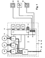
- Fig. 1 are three separately controllable loads 26, 27, 28 connected to the multi-channel built-in dimmer 1.
- Central control element 14 and on-site control 22 are used to control the power level 3 and thus the load 26
- central control element 15 and on-site control 23 serve to control the power level 4 and thus the load 27 and central control element 16 and on-site control 24 are used Control of the power level 5 and thus the load 28.
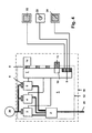
- Fig. 2 are two separately controllable loads 26, 28 connected to the multi-channel built-in dimmer 1, wherein the load 28 with two (parallel connected) power stages 4 and 5 is connected.
- Load 26 is connected to power level 3.
- the central operating element 14 serves to control both the load 26 (by means of activation of the power stage 3) and the load 28 (by means of activation of the power stages 4 and 5).
- the on-site control element 22 serves to control the load 26.
- Both the on-site control element 23 and the on-site control element 24 serve to control the load 28 (for example, from various clearing of a building). Power stages connected in parallel on the load side are also connected in parallel on the control side.
- Fig. 3 are two separately controllable loads 27, 28 connected to the multi-channel built-in dimmer 1, wherein load 27 with two (parallel-connected) power stages 3, 4 is connected.
- the central control element 15 is used to control the power levels 3 and 4 and thus the load 27.
- the central control element 16 serves to control the power level 5 and thus the load 28.
- the local control element 23 is used to control the power levels 3 and 4 and thus to control the load 27.
- the local control 24 is used to control the power level 5 and thus to control the Load 28. Power stages connected in parallel on the load side are also connected in parallel on the control side.
- a single load 26 is connected to all three (parallel) power stages 3, 4, 5 of the multi-channel built-in dimmer 1. It is a relatively powerful load with a power of z. B. 1000 W.
- the central control element 14 is used to control the load 27 and applied accordingly all three power levels 3, 4, 5.
- the load 26 can be selectively controlled by three different local controls 22, 23, 24 decentralized.
- the multi-channel built-in dimmer 1 z. B. equipped with only a single central control element 14 or 15 or 16 controls this central control all power levels or outputs of the dimmer synchronously.
- the processing and control device 7 contains a corresponding logic.
- several central controls can be used, a maximum of one central control per output. Normally, each slot (control element interface 8) of the multi-channel built-in dimmer for inserting a central control element of a particular power level is assigned (default).
- the outputs without central controls according to a predetermined logic of the processing and control device 7 or according to a corresponding specification in the input unit 10 of a central control with controlled use - see embodiment according to Fig. 2 .
- timer controls as central controls, a time control of the individual channels can be done in the desired individual and programmable way.
- the time-independent manual control via private branch operation by means of at least one local control element is optional and possible at any time.
Landscapes
- Circuit Arrangement For Electric Light Sources In General (AREA)
- Selective Calling Equipment (AREA)
Abstract
Description
- Die Erfindung bezieht sich auf einen Mehrkanal-Einbaudimmer gemäß dem Oberbegriff des Anspruchs 1. Der Mehrkanal-Einbaudimmer ist insbesondere zum Einbau in einen zentralen Verteilerschrank geeignet.
- Aus der
DE 102 47 333 A1 ist ein Mehrkanaldimmer bekannt, also ein elektronischer Dimmer, der mehrere Leistungsstufen (Kanäle, Ausgänge) aufweist. Die Leistungsstufen sind für eine optionale lastseitige Parallelschaltung von mindestens zwei der Leistungsstufen eingerichtet. Der Mehrkanaldimmer ist flexibel einsetzbar, so dass er sowohl zur Einzelsteuerung oder Gruppensteuerung einer größeren Anzahl von Verbrauchern kleiner Leistung geeignet ist, als auch zur Steuerung eines einzelnen Verbrauchers oder weniger Verbraucher mit hoher Leistung. - Aus der
DE 10 2005 004 884 B3 ist ein Einbaudimmer bekannt, dessen Dimmer-Lastteil auf seiner Oberseite einen Steckverbinder aufweist, welcher mit einem korrespondierenden Steckverbinder eines Bedienelements elektrisch in Kontakt tritt, wobei ein- und dasselbe Dimmer-Lastteil wahlweise mit verschiedenen Bedienelementen bestückbar ist, wie z. B. - Bedienelement für Drehbedienung,
- Bedienelement für Tastbedienung,
- Bedienelement für Zeitsteuerung,
- Bedienelement für Funksteuerung.
- Der Erfindung liegt die Aufgabe zugrunde, einen universell bedienbaren und einsetzbaren Mehrkanal-Einbaudimmer anzugeben,
- Diese Aufgabe wird in Verbindung mit den Merkmalen des Oberbegriffes erfindungsgemäß durch die im Kennzeichen des Anspruchs 1 angegebenen Merkmale gelöst.
- Die mit der Erfindung erzielbaren Vorteile bestehen insbesondere darin, dass unterschiedliche Lastarten getrennt voneinander oder parallel geschaltet über einen einzigen Mehrkanal-Einbaudimmer angesteuert werden können. Der Mehrkanal-Einbaudimmer gestattet unterschiedliche zentrale Bedienarten, d. h. eine zentrale tast-, dreh- oder zeitabhängige Steuerung, so dass ein breites Anwendungsspektrum abgedeckt wird. Dadurch vereinfachen sich Produktion, Lagerhaltung, Vertrieb und Anwendung des Dimmers. Einen besonderen Vorteil stellt es dar, dass auch bei einem Mehrkanal-Einbaudimmer eine Zeitsteuerung ermöglicht wird, d. h. es ist eine Mehrkanal-Dimmer-Zeitschaltuhr realisierbar. Der Mehrkanal-Einbaudimmer ermöglicht zusätzlich zur Bedienung über mindestens ein zentrales Bedienelement (zentrale Bedienung) als weitere Bedienart eine Vorortbedienung über ein dezentrales Vorort-Bedienelement (dezentrale Bedienung, Nebenstelle). Eine nachträgliche einfache Anpassung an geänderte Kundenwünsche ist ohne Gerätewechsel möglich, d. h. der installierte Mehrkanal-Einbaudimmer wird lediglich extern neu beschaltet und gegebenenfalls über seine zentralen Bedienelemente und/oder eine Eingabeeinheit neu programmiert.
- Weitere Vorteile sind aus der nachstehenden Beschreibung ersichtlich.
- Vorteilhafte Ausgestaltungen der Erfindung sind in den Unteransprüchen gekennzeichnet.
- Die Erfindung wird nachstehend anhand der in der Zeichnung dargestellten Ausführungsbeispiele erläutert. Es zeigen:
- Fig.1
- ein schematisches Schaltschema eines Mehrkanal-Einbaudimmers,
- Fig. 2, 3, 4
- Mehrkanal-Einbaudimmer bei unterschiedlichen Anwendungen.
- In
Fig. 1 ist das Schaltschema eines Mehrkanal-Einbaudimmers, hier Dreikanal-Einbaudimmers schematisch dargestellt. Der Mehrkanal-Einbaudimmer 1 ist in einem Verteilerschrank 19 montiert und weist innerhalb seines Gerätegehäuses 12 folgende Baukomponenten auf: - eine Eingangsstufe 2 mit einem Anschluss für ein speisendes Versorgungsnetz 20,
- mehrere, hier z. B. drei Leistungsstufen 3, 4, 5 (Kanäle, Ausgänge), welche leistungsmäßig mit der Eingangsstufe 2 verbunden sind und jeweils eine Last-Anschlusseinheit 6 (z. B. Schraubanschluss) für den Anschluss von Lasten 26, 27, 28, insbesondere Beleuchtungseinrichtungen, aufweisen,
- eine Verarbeitungs- und Steuereinrichtung 7, welche die Leistungsstufen 3, 4, 5 ausgangsseitig ansteuert und mehrere Bedien-Schnittstellen 8 - vorzugsweise Steckverbinder - für die Bestückung mit zentralen Bedienelementen 14, 15, 16 aufweist, wobei die zentralen Bedienelemente wahlweise als Dreh-Bedienelement, als Tast-Bedienelement oder als Timer-Bedienelement ausgebildet sein können, d. h. bei Einsatz mehrerer Timer-Bedienelemente ist z. B. eine Mehrkanaldimmer-Zeitschaltuhr mit getrennter Zeitsteuerung der einzelnen Kanäle realisierbar,
- eine Bedienelement-Anschlusseinheit 9 der Verarbeitungs- und Steuereinrichtung 7 für den Anschluss (z. B. Schraubanschluss) mehrerer (dezentraler) Vorort-Bedienelemente 22, 23, 24, welche z. B. als manuell betätigbare Dreh-Bedienelemente ("Nebenstelle Drehdimmer") oder Tast-Bedienelemente ("Nebenstelle Taster") ausgebildet sind und in unterschiedlichen Räumen eines Gebäudes installiert sein können,
- eine Eingabeeinheit 10 der Verarbeitungs- und Steuereinrichtung 7, welche über ein manuell betätigbares Eingabeelement 11 (z. B. Tasten oder Touchscreen) beaufschlagbar ist.
- Ein Timer-Bedienelement ermöglicht eine Programmierung, d. h. individuelle Einstellungen hinsichtlich Schaltzeiten (Einschalten der Last / Ausschalten der Last) und Heftigkeit der Last während einer bestimmten Schaltzeit. Es sind mehrere Schaltzeiten pro Tag einstellbar.
- Um das breite Anwendungsspektrum des Mehrkanal-Einbaudimmers zu skizzieren, sollen nachfolgend vier unterschiedliche Anwendungsbeispiele betrachtet werden:
- Beim Ausführungsbeispiel nach
Fig. 1 sind drei getrennt ansteuerbare Lasten 26, 27, 28 am Mehrkanal-Einbaudimmer 1 angeschlossen. Zentrales Bedienelement 14 und Vorort-Bedienelement 22 dienen zur Ansteuerung der Leistungsstufe 3 und damit der Last 26, zentrales Bedienelement 15 und Vorort-Bedienelement 23 dienen zur Ansteuerung der Leistungsstufe 4 und damit der Last 27 und zentrales Bedienelement 16 und Vorort-Bedienelement 24 dienen zur Ansteuerung der Leistungsstufe 5 und damit der Last 28. Beispielsweise sind alle drei zentralen Bedienelemente 4, 15, 16 in Form von Timer-Bedienelementen ausgebildet, wodurch sich eine je Kanal individuell programmierbare Mehrkanal-Dimmer-Zeitschaltuhr ergibt. - Beim Ausführungsbeispiel nach
Fig. 2 sind zwei getrennt ansteuerbare Lasten 26, 28 am Mehrkanal-Einbaudimmer 1 angeschlossen, wobei die Last 28 mit beiden (parallel geschalteten) Leistungsstufen 4 und 5 verbunden ist. Last 26 ist an Leistungsstufe 3 angeschlossen. Das zentrale Bedienelement 14 dient zur Ansteuerung sowohl der Last 26 (mittels Ansteuerung der Leistungsstufe 3) als auch der Last 28 (mittels Ansteuerung der Leistungsstufen 4 und 5). Das Vorort-Bedienelement 22 dient zur Ansteuerung der Last 26. Sowohl das Vorort-Bedienelement 23 als auch das Vorort-Bedienelement 24 dienen zur Ansteuerung der Last 28 (z. B. von verschiedenen Räumens eines Gebäudes aus). Lastseitig parallel geschaltete Leistungsstufen werden auch ansteuerungsseitig parallel geschaltet. - Beim Ausführungsbeispiel nach
Fig. 3 sind zwei getrennt ansteuerbare Lasten 27, 28 am Mehrkanal-Einbaudimmer 1 angeschlossen, wobei Last 27 mit beiden (parallel geschalteten) Leistungsstufen 3, 4 verbunden ist. Das zentrale Bedienelement 15 dient zur Ansteuerung der Leistungsstufen 3 und 4 und damit der Last 27. Das zentrale Bedienelement 16 dient zur Ansteuerung der Leistungsstufe 5 und damit der Last 28. Das Vorort-Bedienelement 23 dient zur Ansteuerung der Leistungsstufen 3 und 4 und damit zur Ansteuerung der Last 27. Das Vorort-Bedienelement 24 dient zur Ansteuerung der Leistungsstufe 5 und damit zur Ansteuerung der Last 28. Lastseitig parallel geschaltete Leistungsstufen werden auch ansteuerungsseitig parallel geschaltet. - Beim Ausführungsbeispiel nach
Fig. 4 ist eine einzige Last 26 an alle drei (parallel geschalteten) Leistungsstufen 3, 4, 5 des Mehrkanal-Einbaudimmers 1 angeschlossen. Es handelt sich hierbei um eine relativ leistungsstarke Last mit einer Leistung von z. B. 1000 W. Das zentrale Bedienelement 14 dient zur Ansteuerung der Last 27 und beaufschlagt demgemäß alle drei Leistungsstufen 3, 4, 5. Die Last 26 kann wahlweise von drei verschiedenen Vorort-Bedienelementen 22, 23, 24 dezentral angesteuert werden. - Für alle Ausführungsbeispiele gilt:
- Liegen der Verarbeitungs- und Steuereinrichtung 7 bezüglich einer Last unterschiedliche Ansteuersignale seitens der zentralen Bedienelemente 14 und/oder 15 und/oder 16 und der dezentralen Vorort-Bedienelemente 22 und/oder 23 und/oder 24 vor, so haben die Ansteuersignale der dezentralen Vorort-Bedienelemente 22 und/oder 23 und/oder 24 Vorrang vor den Ansteuersignalen der zentralen Bedienelemente 14 und/oder 15 und/oder 16.
- Die Verknüpfung zwischen einem zentralen Bedienelement 14 und/oder 15 und/oder 16 und einer zuzuordnenden Leistungsstufe 3 und/oder 4 und/oder 5 respektive der daran angeschlossenen Last wird durch entsprechende Betätigung des manuellen Eingabeelementes 11 der Eingabeeinheit 10 konkret für den speziellen Anwendungsfall vorgegeben. Das gleiche gilt für die Verknüpfung zwischen einem Vorort-Bedienelement 22 und/oder 23 und/oder 24 und einer zuzuordnenden Leistungsstufe 3 und/oder 4 und/oder 5 respektive der daran angeschlossenen Last.
- Wird der Mehrkanal-Einbaudimmer 1 z. B. nur mit einem einzigen zentralen Bedienelement 14 oder 15 oder 16 bestückt, steuert dieses zentrale Bedienelement alle Leistungsstufen bzw. Ausgänge des Dimmers synchron. Die Verarbeitungs- und Steuereinrichtung 7 enthält eine entsprechende Logik. Bei Verwendung des Mehrkanal-Einbaudimmers 1 zur getrennten Steuerung von mehreren Ausgängen können mehrere zentrale Bedienelemente benutzt werden, maximal ein zentrales Bedienelement je Ausgang. Im Normalfall ist jeder Steckplatz (Bedienelement-Schnittstelle 8) des Mehrkanal-Einbaudimmers zum Einstecken eines zentralen Bedienelementes einer bestimmten Leistungsstufe zugeordnet (Grundeinstellung). Bei Verwendung von weniger zentralen Bedienelementen als Ausgängen bzw. Leistungsstufen können die Ausgänge ohne zentrale Bedienelemente nach einer vorgegebenen Logik der Verarbeitungs- und Steuereinrichtung 7 bzw. nach einer entsprechenden Vorgabe in der Eingabeeinheit 10 von einem zentralen Bedienelement mit gesteuert verwenden - siehe Ausführungsbeispiel gemäß
Fig. 2 . Bei Verwendung von Timer-Bedienelementen als zentrale Bedienelemente kann eine Zeitsteuerung der einzelnen Kanäle in gewünschter individueller und programmierbarer Weise erfolgen. Die zeitunabhängige manuelle Steuerung über Nebenstellenbetrieb mittels mindestens eines Vorort-Bedienelements ist optional und jederzeit möglich. - Bei den vorstehend beschriebenen Ausführungsbeispielen wird ein Mehrkanal-Einbaudimmer mit drei Kanälen beschrieben. Die Ausführungen gelten sinngemäß selbstverständlich auch für Mehrkanal-Einbaudimmer mit zwei, vier oder mehr Kanälen.
-
- 1
- Mehrkanal-Einbaudimmer
- 2
- Eingangsstufe
- 3
- erste Leistungsstufe
- 4
- zweite Leistungsstufe
- 5
- dritte Leistungsstufe
- 6
- Last-Anschlusseinheit
- 7
- Verarbeitungs- und Steuereinrichtung
- 8
- Bedienelement-Schnittstelle
- 9
- Bedienelement-Anschlusseinheit
- 10
- Eingabeeinheit
- 11
- manuelles Eingabeelement (z. B. Tasten)
- 12
- Gerätegehäuse
- 13
- ---
- 14
- erstes zentrales Bedienelement
- 15
- zweites zentrales Bedienelement
- 16
- drittes zentrales Bedienelement
- 17
- ---
- 18
- ---
- 19
- Verteilerschrank
- 20
- Versorgungsnetz
- 21
- ---
- 22
- erstes Vorort-Bedienelement
- 23
- zweites Vorort-Bedienelement
- 24
- drittes Vorort-Bedienelement
- 25
- ---
- 26
- erste Last
- 27
- zweite Last
- 28
- dritte Last
Claims (3)
- Mehrkanal-Einbaudimmer (1) mit einer an ein Versorgungsnetz (20) anschließbaren Eingangsstufe (2), mehreren unabhängig voneinander ansteuerbaren Leistungsstufen (3, 4, 5) mit separaten Last-Anschlusseinheiten (6) für den Anschluss einer Last oder mehrerer Lasten (26, 27, 28) und mit einer Verarbeitungs- und Steuereinrichtung (7) in einem gemeinsamen Gerätegehäuse (12), dadurch gekennzeichnet, dass die Verarbeitungs- und Steuereinrichtung (7) für jede ansteuerbare Leistungsstufe (3, 4, 5) mindestens eine individuelle Bedienelement-Schnittstelle (8) zur Bestückung mit einem eigenen zentralen Bedienelement (14, 15, 16) aufweist.
- Mehrkanal-Einbaudimmer nach Anspruch 1, dadurch gekennzeichnet, dass die Verarbeitungs- und Steuereinrichtung (7) eine Eingabeeinheit (10) mit manuellem Eingabeelement (11) für eine individuelle Zuordnung einer Leistungsstufe (3, 4, 5) zu einem zentralen Bedienelement (14, 15, 16) respektive dessen Bedienelement-Schnittstelle (8) aufweist.
- Mehrkanal-Einbaudimmer nach Anspruch 1 oder 2, dadurch gekennzeichnet, dass die Verarbeitungs- und Steuereinrichtung (7) eine Bedienelement-Anschlusseinheit (9) für den Anschluss von dezentralen Vorort-Bedienelementen (22, 23, 24) aufweist.
Applications Claiming Priority (1)
| Application Number | Priority Date | Filing Date | Title |
|---|---|---|---|
| DE102007026609A DE102007026609B3 (de) | 2007-06-08 | 2007-06-08 | Mehrkanal-Einbaudimmer |
Publications (3)
| Publication Number | Publication Date |
|---|---|
| EP2001270A2 true EP2001270A2 (de) | 2008-12-10 |
| EP2001270A3 EP2001270A3 (de) | 2016-12-14 |
| EP2001270B1 EP2001270B1 (de) | 2020-03-04 |
Family
ID=39688510
Family Applications (1)
| Application Number | Title | Priority Date | Filing Date |
|---|---|---|---|
| EP08009436.0A Active EP2001270B1 (de) | 2007-06-08 | 2008-05-23 | Mehrkanal-Einbaudimmer |
Country Status (2)
| Country | Link |
|---|---|
| EP (1) | EP2001270B1 (de) |
| DE (1) | DE102007026609B3 (de) |
Cited By (1)
| Publication number | Priority date | Publication date | Assignee | Title |
|---|---|---|---|---|
| DE102010017088A1 (de) * | 2010-05-26 | 2011-12-01 | Münchner Hybrid Systemtechnik GmbH | Schaltbare Stromversorgung |
Citations (2)
| Publication number | Priority date | Publication date | Assignee | Title |
|---|---|---|---|---|
| DE10247333A1 (de) | 2002-06-06 | 2003-12-24 | Abb Patent Gmbh | Mehrkanaldimmer |
| DE102005004884B3 (de) | 2005-02-03 | 2006-08-31 | Abb Patent Gmbh | Einbaudimmer |
Family Cites Families (4)
| Publication number | Priority date | Publication date | Assignee | Title |
|---|---|---|---|---|
| DE69434232D1 (de) * | 1993-11-12 | 2005-02-17 | Leviton Manufacturing Co | Steuerungsnetz für ein bühnenbeleuchtungssystem |
| DE19728538A1 (de) * | 1997-07-04 | 1999-01-07 | Abb Patent Gmbh | Dimmer |
| DE19738857A1 (de) * | 1997-09-05 | 1999-04-15 | Abb Patent Gmbh | Dimmersystem |
| DE20314200U1 (de) * | 2003-09-11 | 2003-11-06 | Se Lightmanagement Ag, Spreitenbach | Intelligenter Universal-Dimmer |
-
2007
- 2007-06-08 DE DE102007026609A patent/DE102007026609B3/de active Active
-
2008
- 2008-05-23 EP EP08009436.0A patent/EP2001270B1/de active Active
Patent Citations (2)
| Publication number | Priority date | Publication date | Assignee | Title |
|---|---|---|---|---|
| DE10247333A1 (de) | 2002-06-06 | 2003-12-24 | Abb Patent Gmbh | Mehrkanaldimmer |
| DE102005004884B3 (de) | 2005-02-03 | 2006-08-31 | Abb Patent Gmbh | Einbaudimmer |
Cited By (1)
| Publication number | Priority date | Publication date | Assignee | Title |
|---|---|---|---|---|
| DE102010017088A1 (de) * | 2010-05-26 | 2011-12-01 | Münchner Hybrid Systemtechnik GmbH | Schaltbare Stromversorgung |
Also Published As
| Publication number | Publication date |
|---|---|
| EP2001270B1 (de) | 2020-03-04 |
| EP2001270A3 (de) | 2016-12-14 |
| DE102007026609B3 (de) | 2008-09-18 |
Similar Documents
| Publication | Publication Date | Title |
|---|---|---|
| EP1064759A1 (de) | Verfahren zum inbetriebnehmen eines bussystems sowie entsprechendes bussystem | |
| WO2009027129A1 (de) | Verfahren zur inbetriebsetzung eines beleuchtungssystems | |
| EP2837268A1 (de) | Beleuchtungssystem und steuereinheit hierfür | |
| EP2001270B1 (de) | Mehrkanal-Einbaudimmer | |
| EP2897444B1 (de) | Schaltung zur LED-Stromversorgung | |
| EP2009962B1 (de) | Verfahren zur Inbetriebnahme eines Mehrkanaldimmers | |
| EP2502354B1 (de) | Elektrisches installationssystem | |
| EP2658180A1 (de) | Unterputz-Elektro-Installationsgeräte-Baukastensystem | |
| DE102006062751B4 (de) | Multidimmer, welcher universell als Masterdimmer, als Slavedimmer oder als Nebenstelle einsetzbar ist | |
| EP3217765B1 (de) | Vereinfachtes inbetriebnahmekonzept zum ansteuern von aktoren einer gebäudeinstallation | |
| DE102005004884B3 (de) | Einbaudimmer | |
| DE102006033765B3 (de) | Dimmersystem mit mehreren Multidimmern und Multidimmer, welcher universell als Masterdimmer, als Slavedimmer oder als Nebenstelle einsetzbar ist | |
| EP3731039B1 (de) | Elektrisches/elektronisches installationssystem | |
| DE202015102332U1 (de) | Elektrisches/elektronisches Installationsgerät | |
| EP3731042B1 (de) | Elektrisches/elektronisches installationssystem | |
| EP2811599B1 (de) | Elektrisches/elektronisches installationsgerät | |
| EP1843446B1 (de) | Anschlusseinrichtung für die Hausleittechnik | |
| DE102013103677A1 (de) | Verfahren zur Ansteuerung eines Wärmepumpenverbundes | |
| DE102013103678A1 (de) | Verfahren zur Ansteuerung eines Wärmepumpenverbundes | |
| EP1993040A1 (de) | Sensoreinheit mit mehreren Bedien-oder Funktionselementen | |
| DE202018102043U1 (de) | Elektrisches/elektronisches Gerätesystem | |
| EP2582211B1 (de) | DALI Verteilerbox | |
| DE102013206536A1 (de) | Verfahren zum Ansteuern einer Leuchte mit mehreren Teileinheiten | |
| DE102007005995A1 (de) | Bedieneinheit für mindestens eine über einen DALI-Bus betriebene Beleuchtungskomponente | |
| DE202005014643U1 (de) | Dimmersystem |
Legal Events
| Date | Code | Title | Description |
|---|---|---|---|
| PUAI | Public reference made under article 153(3) epc to a published international application that has entered the european phase |
Free format text: ORIGINAL CODE: 0009012 |
|
| AK | Designated contracting states |
Kind code of ref document: A2 Designated state(s): AT BE BG CH CY CZ DE DK EE ES FI FR GB GR HR HU IE IS IT LI LT LU LV MC MT NL NO PL PT RO SE SI SK TR |
|
| AX | Request for extension of the european patent |
Extension state: AL BA MK RS |
|
| PUAL | Search report despatched |
Free format text: ORIGINAL CODE: 0009013 |
|
| AK | Designated contracting states |
Kind code of ref document: A3 Designated state(s): AT BE BG CH CY CZ DE DK EE ES FI FR GB GR HR HU IE IS IT LI LT LU LV MC MT NL NO PL PT RO SE SI SK TR |
|
| AX | Request for extension of the european patent |
Extension state: AL BA MK RS |
|
| RIC1 | Information provided on ipc code assigned before grant |
Ipc: H05B 39/04 20060101ALI20161109BHEP Ipc: H05B 37/02 20060101AFI20161109BHEP |
|
| STAA | Information on the status of an ep patent application or granted ep patent |
Free format text: STATUS: REQUEST FOR EXAMINATION WAS MADE |
|
| 17P | Request for examination filed |
Effective date: 20170508 |
|
| AKX | Designation fees paid |
Designated state(s): AT BE BG CH CY CZ DE DK EE ES FI FR GB GR HR HU IE IS IT LI LT LU LV MC MT NL NO PL PT RO SE SI SK TR |
|
| AXX | Extension fees paid |
Extension state: RS Extension state: MK Extension state: AL Extension state: BA |
|
| STAA | Information on the status of an ep patent application or granted ep patent |
Free format text: STATUS: EXAMINATION IS IN PROGRESS |
|
| 17Q | First examination report despatched |
Effective date: 20180327 |
|
| RAP1 | Party data changed (applicant data changed or rights of an application transferred) |
Owner name: ABB SCHWEIZ AG |
|
| GRAP | Despatch of communication of intention to grant a patent |
Free format text: ORIGINAL CODE: EPIDOSNIGR1 |
|
| STAA | Information on the status of an ep patent application or granted ep patent |
Free format text: STATUS: GRANT OF PATENT IS INTENDED |
|
| INTG | Intention to grant announced |
Effective date: 20191112 |
|
| RIN1 | Information on inventor provided before grant (corrected) |
Inventor name: ULBRICH, STEFAN, DIPL.-ING. Inventor name: BANKSTAHL, JOHANNES, DIPL.-ING. |
|
| GRAS | Grant fee paid |
Free format text: ORIGINAL CODE: EPIDOSNIGR3 |
|
| GRAA | (expected) grant |
Free format text: ORIGINAL CODE: 0009210 |
|
| STAA | Information on the status of an ep patent application or granted ep patent |
Free format text: STATUS: THE PATENT HAS BEEN GRANTED |
|
| AK | Designated contracting states |
Kind code of ref document: B1 Designated state(s): AT BE BG CH CY CZ DE DK EE ES FI FR GB GR HR HU IE IS IT LI LT LU LV MC MT NL NO PL PT RO SE SI SK TR |
|
| REG | Reference to a national code |
Ref country code: GB Ref legal event code: FG4D Free format text: NOT ENGLISH |
|
| REG | Reference to a national code |
Ref country code: CH Ref legal event code: EP |
|
| REG | Reference to a national code |
Ref country code: AT Ref legal event code: REF Ref document number: 1241959 Country of ref document: AT Kind code of ref document: T Effective date: 20200315 |
|
| REG | Reference to a national code |
Ref country code: DE Ref legal event code: R096 Ref document number: 502008017028 Country of ref document: DE |
|
| REG | Reference to a national code |
Ref country code: IE Ref legal event code: FG4D Free format text: LANGUAGE OF EP DOCUMENT: GERMAN |
|
| REG | Reference to a national code |
Ref country code: NL Ref legal event code: FP |
|
| PG25 | Lapsed in a contracting state [announced via postgrant information from national office to epo] |
Ref country code: FI Free format text: LAPSE BECAUSE OF FAILURE TO SUBMIT A TRANSLATION OF THE DESCRIPTION OR TO PAY THE FEE WITHIN THE PRESCRIBED TIME-LIMIT Effective date: 20200304 Ref country code: NO Free format text: LAPSE BECAUSE OF FAILURE TO SUBMIT A TRANSLATION OF THE DESCRIPTION OR TO PAY THE FEE WITHIN THE PRESCRIBED TIME-LIMIT Effective date: 20200604 |
|
| PG25 | Lapsed in a contracting state [announced via postgrant information from national office to epo] |
Ref country code: GR Free format text: LAPSE BECAUSE OF FAILURE TO SUBMIT A TRANSLATION OF THE DESCRIPTION OR TO PAY THE FEE WITHIN THE PRESCRIBED TIME-LIMIT Effective date: 20200605 Ref country code: HR Free format text: LAPSE BECAUSE OF FAILURE TO SUBMIT A TRANSLATION OF THE DESCRIPTION OR TO PAY THE FEE WITHIN THE PRESCRIBED TIME-LIMIT Effective date: 20200304 Ref country code: LV Free format text: LAPSE BECAUSE OF FAILURE TO SUBMIT A TRANSLATION OF THE DESCRIPTION OR TO PAY THE FEE WITHIN THE PRESCRIBED TIME-LIMIT Effective date: 20200304 Ref country code: SE Free format text: LAPSE BECAUSE OF FAILURE TO SUBMIT A TRANSLATION OF THE DESCRIPTION OR TO PAY THE FEE WITHIN THE PRESCRIBED TIME-LIMIT Effective date: 20200304 Ref country code: BG Free format text: LAPSE BECAUSE OF FAILURE TO SUBMIT A TRANSLATION OF THE DESCRIPTION OR TO PAY THE FEE WITHIN THE PRESCRIBED TIME-LIMIT Effective date: 20200604 |
|
| REG | Reference to a national code |
Ref country code: LT Ref legal event code: MG4D |
|
| PG25 | Lapsed in a contracting state [announced via postgrant information from national office to epo] |
Ref country code: PT Free format text: LAPSE BECAUSE OF FAILURE TO SUBMIT A TRANSLATION OF THE DESCRIPTION OR TO PAY THE FEE WITHIN THE PRESCRIBED TIME-LIMIT Effective date: 20200729 Ref country code: RO Free format text: LAPSE BECAUSE OF FAILURE TO SUBMIT A TRANSLATION OF THE DESCRIPTION OR TO PAY THE FEE WITHIN THE PRESCRIBED TIME-LIMIT Effective date: 20200304 Ref country code: ES Free format text: LAPSE BECAUSE OF FAILURE TO SUBMIT A TRANSLATION OF THE DESCRIPTION OR TO PAY THE FEE WITHIN THE PRESCRIBED TIME-LIMIT Effective date: 20200304 Ref country code: LT Free format text: LAPSE BECAUSE OF FAILURE TO SUBMIT A TRANSLATION OF THE DESCRIPTION OR TO PAY THE FEE WITHIN THE PRESCRIBED TIME-LIMIT Effective date: 20200304 Ref country code: CZ Free format text: LAPSE BECAUSE OF FAILURE TO SUBMIT A TRANSLATION OF THE DESCRIPTION OR TO PAY THE FEE WITHIN THE PRESCRIBED TIME-LIMIT Effective date: 20200304 Ref country code: EE Free format text: LAPSE BECAUSE OF FAILURE TO SUBMIT A TRANSLATION OF THE DESCRIPTION OR TO PAY THE FEE WITHIN THE PRESCRIBED TIME-LIMIT Effective date: 20200304 Ref country code: IS Free format text: LAPSE BECAUSE OF FAILURE TO SUBMIT A TRANSLATION OF THE DESCRIPTION OR TO PAY THE FEE WITHIN THE PRESCRIBED TIME-LIMIT Effective date: 20200704 Ref country code: SK Free format text: LAPSE BECAUSE OF FAILURE TO SUBMIT A TRANSLATION OF THE DESCRIPTION OR TO PAY THE FEE WITHIN THE PRESCRIBED TIME-LIMIT Effective date: 20200304 |
|
| REG | Reference to a national code |
Ref country code: DE Ref legal event code: R119 Ref document number: 502008017028 Country of ref document: DE |
|
| PLBE | No opposition filed within time limit |
Free format text: ORIGINAL CODE: 0009261 |
|
| STAA | Information on the status of an ep patent application or granted ep patent |
Free format text: STATUS: NO OPPOSITION FILED WITHIN TIME LIMIT |
|
| PG25 | Lapsed in a contracting state [announced via postgrant information from national office to epo] |
Ref country code: CH Free format text: LAPSE BECAUSE OF NON-PAYMENT OF DUE FEES Effective date: 20200531 Ref country code: MC Free format text: LAPSE BECAUSE OF FAILURE TO SUBMIT A TRANSLATION OF THE DESCRIPTION OR TO PAY THE FEE WITHIN THE PRESCRIBED TIME-LIMIT Effective date: 20200304 Ref country code: LI Free format text: LAPSE BECAUSE OF NON-PAYMENT OF DUE FEES Effective date: 20200531 Ref country code: IT Free format text: LAPSE BECAUSE OF FAILURE TO SUBMIT A TRANSLATION OF THE DESCRIPTION OR TO PAY THE FEE WITHIN THE PRESCRIBED TIME-LIMIT Effective date: 20200304 Ref country code: DK Free format text: LAPSE BECAUSE OF FAILURE TO SUBMIT A TRANSLATION OF THE DESCRIPTION OR TO PAY THE FEE WITHIN THE PRESCRIBED TIME-LIMIT Effective date: 20200304 |
|
| 26N | No opposition filed |
Effective date: 20201207 |
|
| PG25 | Lapsed in a contracting state [announced via postgrant information from national office to epo] |
Ref country code: PL Free format text: LAPSE BECAUSE OF FAILURE TO SUBMIT A TRANSLATION OF THE DESCRIPTION OR TO PAY THE FEE WITHIN THE PRESCRIBED TIME-LIMIT Effective date: 20200304 Ref country code: SI Free format text: LAPSE BECAUSE OF FAILURE TO SUBMIT A TRANSLATION OF THE DESCRIPTION OR TO PAY THE FEE WITHIN THE PRESCRIBED TIME-LIMIT Effective date: 20200304 |
|
| REG | Reference to a national code |
Ref country code: BE Ref legal event code: MM Effective date: 20200531 |
|
| GBPC | Gb: european patent ceased through non-payment of renewal fee |
Effective date: 20200604 |
|
| PG25 | Lapsed in a contracting state [announced via postgrant information from national office to epo] |
Ref country code: LU Free format text: LAPSE BECAUSE OF NON-PAYMENT OF DUE FEES Effective date: 20200523 |
|
| PG25 | Lapsed in a contracting state [announced via postgrant information from national office to epo] |
Ref country code: GB Free format text: LAPSE BECAUSE OF NON-PAYMENT OF DUE FEES Effective date: 20200604 Ref country code: FR Free format text: LAPSE BECAUSE OF NON-PAYMENT OF DUE FEES Effective date: 20200531 Ref country code: IE Free format text: LAPSE BECAUSE OF NON-PAYMENT OF DUE FEES Effective date: 20200523 |
|
| PG25 | Lapsed in a contracting state [announced via postgrant information from national office to epo] |
Ref country code: DE Free format text: LAPSE BECAUSE OF NON-PAYMENT OF DUE FEES Effective date: 20201201 Ref country code: BE Free format text: LAPSE BECAUSE OF NON-PAYMENT OF DUE FEES Effective date: 20200531 |
|
| PG25 | Lapsed in a contracting state [announced via postgrant information from national office to epo] |
Ref country code: TR Free format text: LAPSE BECAUSE OF FAILURE TO SUBMIT A TRANSLATION OF THE DESCRIPTION OR TO PAY THE FEE WITHIN THE PRESCRIBED TIME-LIMIT Effective date: 20200304 Ref country code: MT Free format text: LAPSE BECAUSE OF FAILURE TO SUBMIT A TRANSLATION OF THE DESCRIPTION OR TO PAY THE FEE WITHIN THE PRESCRIBED TIME-LIMIT Effective date: 20200304 Ref country code: CY Free format text: LAPSE BECAUSE OF FAILURE TO SUBMIT A TRANSLATION OF THE DESCRIPTION OR TO PAY THE FEE WITHIN THE PRESCRIBED TIME-LIMIT Effective date: 20200304 |
|
| PGFP | Annual fee paid to national office [announced via postgrant information from national office to epo] |
Ref country code: NL Payment date: 20260520 Year of fee payment: 19 |
|
| PGFP | Annual fee paid to national office [announced via postgrant information from national office to epo] |
Ref country code: AT Payment date: 20260521 Year of fee payment: 19 |