EP2000832A2 - Optical communication system - Google Patents
Optical communication system Download PDFInfo
- Publication number
- EP2000832A2 EP2000832A2 EP08711621A EP08711621A EP2000832A2 EP 2000832 A2 EP2000832 A2 EP 2000832A2 EP 08711621 A EP08711621 A EP 08711621A EP 08711621 A EP08711621 A EP 08711621A EP 2000832 A2 EP2000832 A2 EP 2000832A2
- Authority
- EP
- European Patent Office
- Prior art keywords
- optical
- wavelength
- dispersion
- fiber
- refractive index
- Prior art date
- Legal status (The legal status is an assumption and is not a legal conclusion. Google has not performed a legal analysis and makes no representation as to the accuracy of the status listed.)
- Withdrawn
Links
- 230000003287 optical effect Effects 0.000 title claims abstract description 193
- 238000004891 communication Methods 0.000 title claims abstract description 35
- 239000006185 dispersion Substances 0.000 claims abstract description 141
- 230000005540 biological transmission Effects 0.000 claims abstract description 101
- 239000013307 optical fiber Substances 0.000 claims abstract description 65
- 239000000835 fiber Substances 0.000 claims abstract description 61
- 238000005253 cladding Methods 0.000 claims abstract description 34
- 239000012792 core layer Substances 0.000 claims description 24
- 239000010410 layer Substances 0.000 claims description 14
- 230000007423 decrease Effects 0.000 description 11
- 238000010586 diagram Methods 0.000 description 10
- 238000005452 bending Methods 0.000 description 4
- VYPSYNLAJGMNEJ-UHFFFAOYSA-N Silicium dioxide Chemical compound O=[Si]=O VYPSYNLAJGMNEJ-UHFFFAOYSA-N 0.000 description 3
- 238000012986 modification Methods 0.000 description 3
- 230000004048 modification Effects 0.000 description 3
- 235000012239 silicon dioxide Nutrition 0.000 description 3
- 239000002019 doping agent Substances 0.000 description 2
- 238000004364 calculation method Methods 0.000 description 1
- 239000013078 crystal Substances 0.000 description 1
- 230000000694 effects Effects 0.000 description 1
- 238000005516 engineering process Methods 0.000 description 1
- 238000004519 manufacturing process Methods 0.000 description 1
- 238000000034 method Methods 0.000 description 1
- 239000004038 photonic crystal Substances 0.000 description 1
- 239000000377 silicon dioxide Substances 0.000 description 1
Images


Classifications
-
- G—PHYSICS
- G02—OPTICS
- G02B—OPTICAL ELEMENTS, SYSTEMS OR APPARATUS
- G02B6/00—Light guides; Structural details of arrangements comprising light guides and other optical elements, e.g. couplings
- G02B6/02—Optical fibres with cladding with or without a coating
- G02B6/036—Optical fibres with cladding with or without a coating core or cladding comprising multiple layers
- G02B6/03616—Optical fibres characterised both by the number of different refractive index layers around the central core segment, i.e. around the innermost high index core layer, and their relative refractive index difference
- G02B6/03622—Optical fibres characterised both by the number of different refractive index layers around the central core segment, i.e. around the innermost high index core layer, and their relative refractive index difference having 2 layers only
- G02B6/03627—Optical fibres characterised both by the number of different refractive index layers around the central core segment, i.e. around the innermost high index core layer, and their relative refractive index difference having 2 layers only arranged - +
-
- G—PHYSICS
- G02—OPTICS
- G02B—OPTICAL ELEMENTS, SYSTEMS OR APPARATUS
- G02B6/00—Light guides; Structural details of arrangements comprising light guides and other optical elements, e.g. couplings
- G02B6/02—Optical fibres with cladding with or without a coating
- G02B6/02004—Optical fibres with cladding with or without a coating characterised by the core effective area or mode field radius
- G02B6/02009—Large effective area or mode field radius, e.g. to reduce nonlinear effects in single mode fibres
- G02B6/02014—Effective area greater than 60 square microns in the C band, i.e. 1530-1565 nm
- G02B6/02019—Effective area greater than 90 square microns in the C band, i.e. 1530-1565 nm
-
- G—PHYSICS
- G02—OPTICS
- G02B—OPTICAL ELEMENTS, SYSTEMS OR APPARATUS
- G02B6/00—Light guides; Structural details of arrangements comprising light guides and other optical elements, e.g. couplings
- G02B6/02—Optical fibres with cladding with or without a coating
- G02B6/02214—Optical fibres with cladding with or without a coating tailored to obtain the desired dispersion, e.g. dispersion shifted, dispersion flattened
- G02B6/0228—Characterised by the wavelength dispersion slope properties around 1550 nm
-
- G—PHYSICS
- G02—OPTICS
- G02B—OPTICAL ELEMENTS, SYSTEMS OR APPARATUS
- G02B6/00—Light guides; Structural details of arrangements comprising light guides and other optical elements, e.g. couplings
- G02B6/02—Optical fibres with cladding with or without a coating
- G02B6/02295—Microstructured optical fibre
- G02B6/02314—Plurality of longitudinal structures extending along optical fibre axis, e.g. holes
- G02B6/02342—Plurality of longitudinal structures extending along optical fibre axis, e.g. holes characterised by cladding features, i.e. light confining region
-
- G—PHYSICS
- G02—OPTICS
- G02B—OPTICAL ELEMENTS, SYSTEMS OR APPARATUS
- G02B6/00—Light guides; Structural details of arrangements comprising light guides and other optical elements, e.g. couplings
- G02B6/24—Coupling light guides
- G02B6/26—Optical coupling means
- G02B6/28—Optical coupling means having data bus means, i.e. plural waveguides interconnected and providing an inherently bidirectional system by mixing and splitting signals
- G02B6/293—Optical coupling means having data bus means, i.e. plural waveguides interconnected and providing an inherently bidirectional system by mixing and splitting signals with wavelength selective means
- G02B6/29371—Optical coupling means having data bus means, i.e. plural waveguides interconnected and providing an inherently bidirectional system by mixing and splitting signals with wavelength selective means operating principle based on material dispersion
- G02B6/29374—Optical coupling means having data bus means, i.e. plural waveguides interconnected and providing an inherently bidirectional system by mixing and splitting signals with wavelength selective means operating principle based on material dispersion in an optical light guide
- G02B6/29376—Optical coupling means having data bus means, i.e. plural waveguides interconnected and providing an inherently bidirectional system by mixing and splitting signals with wavelength selective means operating principle based on material dispersion in an optical light guide coupling light guides for controlling wavelength dispersion, e.g. by concatenation of two light guides having different dispersion properties
- G02B6/29377—Optical coupling means having data bus means, i.e. plural waveguides interconnected and providing an inherently bidirectional system by mixing and splitting signals with wavelength selective means operating principle based on material dispersion in an optical light guide coupling light guides for controlling wavelength dispersion, e.g. by concatenation of two light guides having different dispersion properties controlling dispersion around 1550 nm, i.e. S, C, L and U bands from 1460-1675 nm
-
- G—PHYSICS
- G02—OPTICS
- G02B—OPTICAL ELEMENTS, SYSTEMS OR APPARATUS
- G02B6/00—Light guides; Structural details of arrangements comprising light guides and other optical elements, e.g. couplings
- G02B6/02—Optical fibres with cladding with or without a coating
- G02B6/02214—Optical fibres with cladding with or without a coating tailored to obtain the desired dispersion, e.g. dispersion shifted, dispersion flattened
- G02B6/02219—Characterised by the wavelength dispersion properties in the silica low loss window around 1550 nm, i.e. S, C, L and U bands from 1460-1675 nm
- G02B6/02252—Negative dispersion fibres at 1550 nm
- G02B6/02261—Dispersion compensating fibres, i.e. for compensating positive dispersion of other fibres
-
- G—PHYSICS
- G02—OPTICS
- G02B—OPTICAL ELEMENTS, SYSTEMS OR APPARATUS
- G02B6/00—Light guides; Structural details of arrangements comprising light guides and other optical elements, e.g. couplings
- G02B6/24—Coupling light guides
- G02B6/26—Optical coupling means
- G02B6/28—Optical coupling means having data bus means, i.e. plural waveguides interconnected and providing an inherently bidirectional system by mixing and splitting signals
- G02B6/293—Optical coupling means having data bus means, i.e. plural waveguides interconnected and providing an inherently bidirectional system by mixing and splitting signals with wavelength selective means
- G02B6/29304—Optical coupling means having data bus means, i.e. plural waveguides interconnected and providing an inherently bidirectional system by mixing and splitting signals with wavelength selective means operating by diffraction, e.g. grating
- G02B6/29316—Light guides comprising a diffractive element, e.g. grating in or on the light guide such that diffracted light is confined in the light guide
- G02B6/29317—Light guides of the optical fibre type
-
- G—PHYSICS
- G02—OPTICS
- G02B—OPTICAL ELEMENTS, SYSTEMS OR APPARATUS
- G02B6/00—Light guides; Structural details of arrangements comprising light guides and other optical elements, e.g. couplings
- G02B6/24—Coupling light guides
- G02B6/26—Optical coupling means
- G02B6/28—Optical coupling means having data bus means, i.e. plural waveguides interconnected and providing an inherently bidirectional system by mixing and splitting signals
- G02B6/293—Optical coupling means having data bus means, i.e. plural waveguides interconnected and providing an inherently bidirectional system by mixing and splitting signals with wavelength selective means
- G02B6/29379—Optical coupling means having data bus means, i.e. plural waveguides interconnected and providing an inherently bidirectional system by mixing and splitting signals with wavelength selective means characterised by the function or use of the complete device
- G02B6/29392—Controlling dispersion
- G02B6/29394—Compensating wavelength dispersion
Definitions
- the present invention relates to an optical communication system in which an optical fiber is used as an optical transmission path.
- PBGF photonic bandgap fiber
- a Bragg grating is constructed in a cladding region by periodically arranging a medium such as air that has a different refractive index than that of the cladding region.
- the photonic bandgap fiber transmits a particular operation wavelength from a gap formed by the Bragg grating with respect to a core region that is formed by a hole in the cladding region.
- a commercial-based photonic bandgap fiber is disclosed in Nonpatent Literature 1.
- Nonpatent Literature 2 discloses transmission characteristics of a dispersion management soliton that is constructed by combining a PCF and a dispersion compensating fiber (DCF), and has a 100 km-long transmission path and a transmission rate of 10 Gb/s.
- Nonpatent Literature 1 CRYSTAL FIBRE A/S, "AIRGUIDING HOLLOW-CORE REGION PHOTONIC BANDGAP FIBERS SELECTED DATASHEETS HC-1550-02, HC19-1550-01", [online], [searched on February 8, 2007], Internet (URL: http://www.crystal-fibre.com/products/airguide.shtm)
- Nonpatent Literature 2 K. Kurokawa, et al., “Penalty-Free Dispersion-Managed Soliton Transmission over 100km Low Loss PCF", Proc. OFC PDP21 (2005).
- the photonic bandgap fiber also has the potential to be used as a communication fiber because of low optical nonlinearity and potential of low transmission loss.
- the operation wavelength of an optical signal that the photonic bandgap fiber uses for communication has such wavelength dispersion and a dispersion slope that a D/S ratio obtained by dividing the wavelength dispersion by the dispersion slope is extremely small.
- the wavelength dispersion and the dispersion slope cannot be compensated even by using a dispersion compensator of the conventional dispersion compensating fiber. As a result, it is not possible to perform long-haul wideband transmission of an optical signal.
- the present invention has been achieved to solve the above problems in the conventional technology and it is an object of the present invention to provide an optical communication system in which wavelength dispersion characteristics of an optical transmission path are easily compensated while making use of low optical nonlinearity and low transmission loss characteristic of a photonic bandgap fiber.
- an optical communication system employs an optical fiber as an optical transmission path.
- the optical transmission path includes a photonic bandgap fiber that includes a core formed by a hole at a center of the photonic bandgap fiber, an outer cladding formed around the core, and an inner cladding formed between the core and the outer cladding, in which a Bragg grating is formed by periodically arranging a medium having a refractive index different from a refractive index of the outer cladding, and transmits a light of a predetermined operation wavelength within a photonic bandgap formed by the Bragg grating; and an optical fiber that is connected to the photonic bandgap fiber, and has wavelength dispersion equal to or larger than 0 ps/nm/km and smaller than wavelength dispersion of the photonic bandgap fiber and D/S value, which is obtained by dividing the wavelength dispersion by dispersion slope, larger than D/S value of the photonic band
- the optical communication system according to the present invention is featured in that, in the above-described invention, the optical fiber has the wavelength dispersion equal to or smaller than 25 ps/nm/km and the D/S value equal to or larger than 100 nm.
- the optical communication system is featured in that, in the above-described invention, the optical transmission path further includes a dispersion compensator that is connected to either one of the photonic bandgap fiber and the optical fiber, and has negative wavelength dispersion and negative dispersion slope for compensating a sum of wavelength dispersions and an average dispersion slope of the photonic bandgap fiber and the optical fiber at the operation wavelength.
- a dispersion compensator that is connected to either one of the photonic bandgap fiber and the optical fiber, and has negative wavelength dispersion and negative dispersion slope for compensating a sum of wavelength dispersions and an average dispersion slope of the photonic bandgap fiber and the optical fiber at the operation wavelength.
- the optical communication system according to the present invention is featured in that, in the above-described invention, the dispersion compensator has D/S value of 70% to 130% of average D/S value of the photonic bandgap fiber and the optical fiber.
- the optical communication system according to the present invention is featured in that, in the above-described invention, the operation wavelength is 800 nm to 1700 nm.
- the optical communication system according to the present invention is featured in that, in the above-described invention, the operation wavelength is 1530 nm to 1625 nm.
- the optical communication system is featured in that, in the above-described invention, the optical fiber includes a center core region, an outer core layer that is formed on an outer circumference of the center core region and has a refractive index lower than a refractive index of the center core region, and a cladding layer that is formed on an outer circumference of the outer core layer and has a refractive index lower than the refractive index of the center core region and larger than the refractive index of the outer core layer.
- wavelength dispersion is equal to or smaller than 25 ps/nm/km, D/S value equal to or larger than 300 nm, effective core area equal to or larger than 80 ⁇ m 2 , and optical loss equal to or smaller than 0.25 dB/km.
- the optical communication system according to the present invention is featured in that, in the above-described invention, the optical fiber includes a center core region, an outer core layer that is formed on an outer circumference of the center core region and has a refractive index lower than a refractive index of the center core region, and a cladding layer that is formed on an outer circumference of the outer core layer and has a refractive index lower than the refractive index of the center core region and larger than the refractive index of the outer core layer.
- the relative refractive index difference ⁇ 1 between the center core region and the cladding layer is 0.15% to 0.4%
- the relative refractive index difference ⁇ 2 between the outer core layer and the cladding layer is -0.35% to -0.05%
- the ratio b/a of outer diameter of the core layer to diameter of the center core region of 1.5 to 6.
- the optical communication system according to the present invention is featured in that, in the above-described invention, the dispersion compensator has wavelength dispersion equal to or smaller than -80 ps/nm/km at the operation wavelength.
- An optical communication system includes an optical transmission path constructed by using a photonic bandgap fiber and an optical fiber.
- the optical fiber has wavelength dispersion equal to or larger than 0 ps/nm/km but smaller than wavelength dispersion of the photonic bandgap fiber and a D/S ratio, which is obtained by dividing the wavelength dispersion by a dispersion slope, larger than a D/S ratio of the photonic bandgap fiber.
- a photonic bandgap fiber is referred to as a PBGF
- a dispersion compensating fiber is referred to as a DCF.
- a cutoff wavelength ( ⁇ c ) mentioned below is a fiber cutoff wavelength defined in ITU-T (International Telecommunication Union Telecommunication Standardization Sector) recommendation G.650.1. Similarly, all other terms mentioned below but not particularly defined follow ITU-T recommendation G.650.1.
- FIG. 1 is a block diagram of an optical communication system according to an embodiment of the present invention.
- an optical communication system 10 includes an optical transmitter 5 that transmits an optical signal, optical repeaters 7-1 to 7-n-1 that regeneratively repeat the optical signal transmitted by the optical transmitter 5, an optical receiver 6 that receives the optical signal, optical transmission paths 4-1 to 4-n that connect the optical transmitter 5, the optical repeaters 7-1 to 7-n-1, and the optical receiver 6 for the transmission of the optical signal.
- 'n' is an integer equal to or larger than 2.
- the optical transmission paths 4-1 to 4-n include PBGFs 1-1 to 1-n, optical fibers 2-1 to 2-n that are connected to the PBGFs 1-1 to 1-n by connection points C-1 to C-n, and dispersion compensators 3-1 to 3-n that are arranged adjacent to and are connected to the optical fibers 2-1 to 2-n.
- the parts of the optical communication system other than the PBGFs 1-1 to 1-n, the optical fibers 2-1 to 2-n, and the dispersion compensators 3-1 to 3-n in the optical transmission paths 4-1 to 4-n are made of a standard single-mode optical fiber and the like.
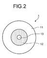
- Fig. 2 is a schematic cross-sectional diagram of a PBGF 1 according to the embodiment.
- Each of the PBGFs 1-1 to 1-n has an identical configuration to that of the PBGF 1, which in turn is identical to that disclosed in Nonpatent Literature 1.
- the PBGF 1 includes an outer cladding region 11, an inner cladding region 12 in which a Bragg grating is fabricated by periodically arranging minute holes that have a different refractive index than that of the outer cladding region 11, and a core region 13 formed by a hole near the center portion of the PBGF 1.
- the PBGF 1 transmits a light of an operation wavelength from a photonic bandgap formed by the Bragg grating.
- the operation wavelength is, e.g., a center wavelength of 1550 nm of the photonic bandgap.
- the PBGF 1 has large wavelength dispersion equal to or larger than 50 ps/nm/km and a large dispersion slope equal to or larger than 0.5 ps/nm 2 /km.
- the optical fibers 2-1 to 2-n have wavelength dispersion equal to or larger than 0 ps/nm/km but smaller than wavelength dispersion of the PBGFs 1-1 to 1-n and a D/S ratio, which is obtained by dividing the wavelength dispersion by a dispersion slope, larger than D/S ratios of the PBGFs 1-1 to 1-n. Consequently, as compared to a case when an optical transmission path having length equal to that of the optical transmission paths 4-1 to 4-n is constructed by using only a PBGF, the sum of wavelength dispersion in the optical transmission paths 4-1 to 4-n decreases by a large margin and the D/S ratio thereof increases by a large margin.
- FIG. 3 is a schematic cross-sectional diagram of an optical fiber 2 according to the embodiment of the present invention.
- Each of the optical fibers 2-1 to 2-n has an identical configuration to that of the optical fiber 2.
- the optical fiber 2 includes a center core region 21, an outer core layer 22 that is formed around the circumference of the center core region 21 and has a refractive index smaller than that of the center core region 21, and a cladding layer 23 that is formed around the circumference of the outer core layer 22 and has a refractive index smaller than that of the center core region 21 but larger than that of the outer core layer 22.
- the center core region 21 has a relative refractive index difference ⁇ 1 of 0.15% to 0.4% with respect to the cladding layer 23.
- the outer core layer 22 has a relative refractive index difference ⁇ 2 of -0.35% to -0.05% with respect to the cladding layer 23.
- An external diameter 2b of the outer core layer 22 has a relative b/a of 1.5 to 6 with respect to a diameter 2a of the center core region 21.
- the D/S ratio of the optical fiber 2 becomes equal to or larger than 100 nm, particularly equal to or larger than 300 nm.
- An effective core area of the optical fiber 2 becomes equal to or larger than 80 ⁇ m 2 .
- the bending loss of the optical fiber 2 also decreases sufficiently, in addition to the fact that the effective core area increases as described above. Because ⁇ 2 lies in the abovementioned range, the bending loss of the optical fiber 2 also decreases sufficiently, in addition to the fact that the wavelength dispersion and the dispersion slope are adjusted as described above. Because b/s lies in the abovementioned range, the increase in the manufacturing cost due to the addition of a refractive-index adjusting dopant such as Ge or F can be curbed and the bending loss can be sufficiently reduced.
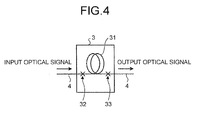
- Fig. 4 is a schematic block diagram of a dispersion compensator 3 according to the embodiment.
- Each of the dispersion compensators 3-1 to 3-n has an identical configuration to that of the dispersion compensator 3.
- the dispersion compensator 3 is a fiber-based dispersion compensator that is connected to a DCF 31 via connection points 32 and 33.
- the dispersion compensator 3 has negative wavelength dispersion that compensates the sum of wavelength dispersion of the PBGF 1 and the optical fiber 2, and a negative dispersion slope that compensates the average dispersion slope of the PBGF 1 and the optical fiber 2.
- the sum of wavelength dispersion of the optical transmission paths of the PBGF 1 and the optical fiber 2 decreases by a large margin and the D/S ratio thereof increases by a large margin.
- the dispersion compensator 3 having wavelength dispersion of about -80 ps/nm/km to -180 ps/nm/km and a D/S ratio of about 250 nm to 350 nm can be used to easily and sufficiently perform the dispersion compensation of, e.g., an optical transmission path constructed by using a conventional standard single-mode optical fiber (SMF).
- SMF standard single-mode optical fiber
- the wavelength dispersion and the dispersion slope can be compensated by using a conventional low-cost dispersion compensator while making use low optical nonlinearity and low transmission loss characteristic of the PBGFs 1-1 to 1-n. As a result, it becomes possible to perform long-haul wideband transmission of an optical signal.
- the strength of an optical signal is maximum in an output unit of the optical transmitter 5 or the optical repeaters 7-1 to 7-n-1.
- Fig. 5 is a table for explaining exemplary optical characteristics of the optical fiber 2 shown in Fig. 3 .
- Fig. 6 is a table for explaining exemplary optical characteristics of the DCF 31 shown in Fig. 4 .
- ⁇ 1 is 0.3%
- ⁇ 2 is -0.2%
- b/a is 4.0
- 2a is 13.5 ⁇ m.
- "D" represents the wavelength dispersion
- “Slope” represents the dispersion slope
- “MFD” represents a mold field diameter
- Aeff represents the effective core area
- ⁇ c represents the cutoff wavelength.
- the bending loss is a value when 16 turns are wound at a diameter of 20 mm.
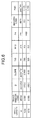
- Fig. 7 is a table for explaining a sum of wavelength dispersion, an average dispersion slope, and an average D/S ratio at a wavelength of 1550 nm in an optical transmission path that is constructed by varying a ratio of lengths of the PBGF 1 shown in Fig. 2 and the optical fiber 2 shown in Fig. 3 .
- the PBGF 1 has an identical configuration to that disclosed in Nonpatent Literature 1.
- the PBGF 1 has wavelength dispersion of 97 ps/nm/km and a dispersion slope of 0.5 ps/nm 2 /km.
- each of an "optical transmission path 1" to an "optical transmission path 3" is 100 km long.
- the "optical transmission path 1" is constructed by using only a 100 km-long PBGF 1.
- the "optical transmission path 2" is constructed by using a 50 km-long PBGF 1 and a 50 km-long optical fiber 2.
- the “optical transmission path 3" is constructed by using a 20 km-long PBGF 1 and an 80 km-long optical fiber 2.
- Fig. 7 in the case of the "optical transmission path 2" and the “optical transmission path 3" constructed by using the PBGF 1 and the optical fiber 2, the sum of wavelength dispersion and the average dispersion slope of decreases, while the average D/S ratio increases. Thus, it becomes easier to perform the dispersion compensation as compared to the "optical transmission path 1" constructed by using only the PBGF 1.
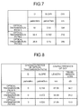
- Fig. 8 is a table for explaining a sum of wavelength dispersion and an average dispersion slope at the wavelength of 1550 nm, and a DCF length and an optical loss when a dispersion compensator, which uses the DCF shown in Fig. 6 , is connected to each optical transmission path shown in Fig. 7 .
- the length of each DCF is adjusted such that the wavelength dispersion at the wavelength of 1550 nm in the corresponding optical transmission path becomes zero.
- the residual average dispersion slope decreases by a larger amount in the case of the "optical transmission path 2" and the "optical transmission path 3" constructed by using the PBGF 1 and the optical fiber 2.
- the optical transmission path 2" and the “optical transmission path 3" suitable for wideband transmission of an optical signal.
- the necessary length of the DCF decreases by a larger amount and the optical loss is equal to or smaller than 22 dB in the case of the "optical transmission path 2" and the “optical transmission path 3".
- the optical loss can be easily compensated by using, e.g., an erbium-doped optical amplifier (EDFA).
- EDFA erbium-doped optical amplifier
- Fig. 9 is a table for explaining a sum of wavelength dispersion, an average dispersion slope, and an average D/S ratio at a wavelength of 1570 nm in an optical transmission path that is constructed by varying a ratio of lengths of the PBGF 1 shown in Fig. 2 and the optical fiber 2 shown in Fig. 3 .
- the PBGF 1 has an identical configuration to that disclosed in Nonpatent Literature 1.
- the PBGF 1 has wavelength dispersion equal to 50 ps/nm/km and a dispersion slope equal to 1.5 ps/nm 2 /km.
- each of an "optical transmission path 4" to an "optical transmission path 6" is 100 km long.
- the "optical transmission path 4" is constructed by using only a 100 km-long PBGF 1.
- the "optical transmission path 5" is constructed by using a 50 km-long PBGF 1 and a 50 km-long optical fiber 2.
- the "optical transmission path 6" is constructed by using a 20 km-long PBGF 1 and an 80 km-long optical fiber 2.
- Fig. 9 in the case of the "optical transmission path 5" and the “optical transmission path 6" constructed by using the PBGF 1 and the optical fiber 2, the sum of wavelength dispersion and the average dispersion slope decreases, while the average D/S ratio increases. Thus, it becomes easier to perform the dispersion compensation as compared to the "optical transmission path 4" constructed by using only the PBGF 1.
- Fig. 10 is a table for explaining a sum of wavelength dispersion and an average dispersion slope at the wavelength of 1570 nm, and a DCF length and an optical loss when a dispersion compensator, which uses the DCF shown in Fig. 6 , is connected to each optical transmission path shown in Fig. 9 .
- the length of each DCF is adjusted such that the wavelength dispersion at the wavelength of 1570 nm in the corresponding optical transmission path becomes zero.
- the residual average dispersion slope decreases by a larger amount in the case of the "optical transmission path 5" and the "optical transmission path 6" constructed by using the PBGF 1 and the optical fiber 2.
- the optical transmission path 5" and the “optical transmission path 6" suitable for wideband transmission of an optical signal. Moreover, as compared to the “optical transmission path 4", the necessary length of the DCF and the optical loss decreases in the case of the "optical transmission path 5" and the “optical transmission path 6". As a result, the optical loss can be easily compensated by using an optical amplifier.
- Fig. 11 is a table for explaining a DCF length and an optical loss when a dispersion compensator that uses a high FOM DCF is connected to each optical transmission path shown in Figs. 7 and 9 such that the wavelength dispersion at the wavelength of 1550 nm or at the wavelength of 1570 nm becomes zero.
- the wavelength dispersion of the high FOM DCF is 250 ps/nm/km and the optical loss thereof is 0.6 dB/km at each of the wavelength of 1550 nm and the wavelength of 1570 nm.
- the DCF length and the optical loss can be reduced by larger amounts as compared to the results shown in Figs. 8 and 10 .
- the DCF length is 57.06 km and the optical loss is 34.2 dB in Fig. 8 .
- the DCF length is reduced to 38.8 km and the optical loss is reduced to 23.3 dB in Fig. 11 .
- the optical loss can be reduced by larger than 10 dB.
- the DCF length is 27.03 km and the optical loss is 13.5 dB in Fig. 10 .
- the DCF length is reduced to 20.0 km and the optical loss is reduced to 12 dB in Fig. 11 .
- the optical loss can be reduced by about 1.5 dB.
- the optical fiber 2 has the refractive index profile shown in Fig. 3 .
- the optical fiber 2 can be made of a silica-based optical fiber.
- a predetermined amount of Ge can be added to the center core region 21, a predetermined amount of F can be added to the outer core layer 22, while the cladding layer 23 can be made of pure silica without adding thereto a refractive-index adjusting dopant.
- Another way of achieving the abovementioned refractive index profile is to make the center core region 21 of pure silica, and to add a predetermined amount of F to each of the outer core layer 22 and the cladding layer 23. If the center core region 21 is made of pure silica, the optical loss of the optical fiber 2 can be reduced to about 0.17 dB/km. Moreover, because Ge is not added to the center core region 21, it becomes possible to further reduce the optical nonlinearity.
- the wavelength compensation rate is obtained by Equation (1).
- wavelength compensation rate (average D/S ratio of optical transmission path)/(D/S ratio of DCF) ⁇ 100 (1)
- DCF 31 having a wavelength compensation rate of 70% to 130% to enable compensation of the wavelength dispersion over a large bandwidth.
- the D/S ratio of the DCF 31 is 283 nm.
- the wavelength compensation rate in the "optical transmission path 1" is about 68%
- the wavelength compensation rate in the "optical transmission path 2" improves to about 74%
- the wavelength compensation rate in the "optical transmission path 3" improves to about 86%.
- the use of the DCF 31 is not limited to an optical transmission path using an SMF.
- a nonzero dispersion-shifted fiber NZ-DSF
- the D/S ratio is smaller and equal to, e.g., 100 nm.
- the wavelength compensation rate in the "optical transmission path 6" can improve to 81%.
- a suitable type of the DCF 31 can be selected depending on the average D/S ratio of the PBGF 1 and the optical fiber 2.
- the center wavelength of the PBGF 1 is described to be 1550 nm within a C-band (1530 nm to 1565 nm) and 1570 nm within an L-band (1565 nm to 1625 nm).
- a PBGF can be suitably selected such that a center wavelength thereof is within 800 nm to 1700 nm, which is the bandwidth to achieve low optical loss in a silica glass optical fiber.
- a fiber-based dispersion compensator is used.
- a fiber Bragg grating dispersion compensator is also possible to use.
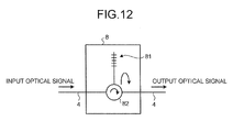
- Fig. 12 is a schematic block diagram of a fiber Bragg grating dispersion compensator according to a modification of the embodiment.
- a fiber Bragg grating dispersion compensator 8 includes a dispersion compensation fiber Bragg grating 81 and an optical circulator 82. Input ports of the optical circulator 82 are connected to an optical transmission path 4, 4 and the dispersion compensation fiber Bragg grating 81.
- An optical signal having a distorted waveform due to waveform dispersion enters the optical circulator 82 from the left side of the optical transmission path 4 in Fig. 12 .
- the optical circulator 82 outputs the optical signal to the dispersion compensation fiber Bragg grating 81.
- the dispersion compensation fiber Bragg grating 81 performs distributive reflection of the received optical signal by using a grating fabricated in a core region, fixes the wavelength distortion of the optical signal, and outputs the optical signal to the optical circulator 82.
- the optical circulator 82 then outputs the optical signal without wavelength distortion in the optical transmission path 4 from the right side in Fig. 12 . In this way, the fiber Bragg grating dispersion compensator 8 can compensate the wavelength dispersion at an operation wavelength in the optical transmission path 4.
- the present invention can be suitably implemented in an optical transmission system that performs wideband, high-capacity, and long-haul transmission.
Landscapes
- Physics & Mathematics (AREA)
- Chemical & Material Sciences (AREA)
- Dispersion Chemistry (AREA)
- General Physics & Mathematics (AREA)
- Optics & Photonics (AREA)
- Optical Communication System (AREA)
- Optical Fibers, Optical Fiber Cores, And Optical Fiber Bundles (AREA)
Applications Claiming Priority (2)
| Application Number | Priority Date | Filing Date | Title |
|---|---|---|---|
| JP2007046255A JP2008209654A (ja) | 2007-02-26 | 2007-02-26 | 光通信システム |
| PCT/JP2008/052815 WO2008105284A1 (ja) | 2007-02-26 | 2008-02-20 | 光通信システム |
Publications (2)
| Publication Number | Publication Date |
|---|---|
| EP2000832A2 true EP2000832A2 (en) | 2008-12-10 |
| EP2000832A9 EP2000832A9 (en) | 2009-04-08 |
Family
ID=39721119
Family Applications (1)
| Application Number | Title | Priority Date | Filing Date |
|---|---|---|---|
| EP08711621A Withdrawn EP2000832A2 (en) | 2007-02-26 | 2008-02-20 | Optical communication system |
Country Status (4)
| Country | Link |
|---|---|
| US (1) | US7805040B2 (ja) |
| EP (1) | EP2000832A2 (ja) |
| JP (1) | JP2008209654A (ja) |
| WO (1) | WO2008105284A1 (ja) |
Families Citing this family (4)
| Publication number | Priority date | Publication date | Assignee | Title |
|---|---|---|---|---|
| JP5520622B2 (ja) * | 2010-01-29 | 2014-06-11 | 古河電気工業株式会社 | フォトニックバンドギャップファイバの製造方法およびフォトニックバンドギャップファイバ |
| JP5619516B2 (ja) | 2010-08-04 | 2014-11-05 | 古河電気工業株式会社 | 光ファイバ |
| CN108885303B (zh) * | 2016-04-01 | 2020-09-01 | 株式会社藤仓 | 光纤及其制造方法 |
| US10845268B1 (en) * | 2019-06-03 | 2020-11-24 | Ciena Corporation | Monitorable hollow core optical fiber |
Family Cites Families (5)
| Publication number | Priority date | Publication date | Assignee | Title |
|---|---|---|---|---|
| JP4293156B2 (ja) * | 1999-04-13 | 2009-07-08 | 住友電気工業株式会社 | 光ファイバ及びそれを含む光通信システム |
| WO2001014917A1 (en) * | 1999-08-20 | 2001-03-01 | The Furukawa Electric Co., Ltd. | Optical fiber and optical transmission line including the same |
| EP1263155A1 (en) * | 2001-05-29 | 2002-12-04 | Aston Photonic Technologies Ltd. | Chromatic dispersion compensation in an optical transmission system |
| JP4123823B2 (ja) * | 2002-05-17 | 2008-07-23 | 住友電気工業株式会社 | 分散補償ユニットおよび光通信システム |
| JP2008096933A (ja) | 2006-10-16 | 2008-04-24 | Furukawa Electric Co Ltd:The | 光通信システムおよび分散補償光ファイバ |
-
2007
- 2007-02-26 JP JP2007046255A patent/JP2008209654A/ja active Pending
-
2008
- 2008-02-20 EP EP08711621A patent/EP2000832A2/en not_active Withdrawn
- 2008-02-20 WO PCT/JP2008/052815 patent/WO2008105284A1/ja not_active Ceased
- 2008-08-05 US US12/185,841 patent/US7805040B2/en not_active Expired - Fee Related
Non-Patent Citations (1)
| Title |
|---|
| See references of WO2008105284A1 * |
Also Published As
| Publication number | Publication date |
|---|---|
| EP2000832A9 (en) | 2009-04-08 |
| US20090080844A1 (en) | 2009-03-26 |
| US7805040B2 (en) | 2010-09-28 |
| JP2008209654A (ja) | 2008-09-11 |
| WO2008105284A1 (ja) | 2008-09-04 |
Similar Documents
| Publication | Publication Date | Title |
|---|---|---|
| CA2277332C (en) | Dispersion-flattened optical fiber | |
| US5838867A (en) | Dispersion compensating fiber and optical transmission system including the same | |
| US7881579B2 (en) | Optical transmission system and dispersion-compensating optical fiber | |
| JP3760557B2 (ja) | 分散補償ファイバ及びそれを含む光伝送システム | |
| US20090123122A1 (en) | Optical fibers and optical transmission systems | |
| JPWO2000025158A1 (ja) | 分散補償光ファイバおよびその分散補償光ファイバを用いた波長多重光伝送路 | |
| US6603913B1 (en) | Single-mode optical fiber having multiple cladding regions for dispersion compensation | |
| JPWO2001001179A1 (ja) | 光伝送路 | |
| US7773845B2 (en) | Optical fiber and optical-fiber transmission line | |
| JP4252894B2 (ja) | 分散及び分散スロープ補償光ファイバ及びこれを含む伝送リンク | |
| WO2014038512A1 (ja) | 光ファイバ | |
| CN101446663A (zh) | 一种改进的具有大模场分布的非零色散位移单模光纤 | |
| US7693380B2 (en) | Optical transmission line and optical transmission system | |
| JP5112582B2 (ja) | 正の波長分散を備えるnz−dsfファイバの波長分散補償のためのファイバ | |
| US20080219667A1 (en) | Optical communication system and dispersion-compensating optical fiber | |
| US6952518B2 (en) | Dispersion-shifted single-mode fiber having low dispersion slope for large capacity transmission | |
| US7805040B2 (en) | Optical communication system | |
| US20030147610A1 (en) | Optical fiber, optical transmission line and optical communications system | |
| KR100749295B1 (ko) | 분산 보상 광 화이버, 광 전송로 및 분산 보상 모듈 | |
| JP4101497B2 (ja) | 正の波長分散をもつ光ファイバ内の波長分散のインライン補償のための光ファイバ | |
| US7978949B2 (en) | Optical fibers and optical transmission systems | |
| JP4134547B2 (ja) | 光伝送路 | |
| EP1259840B1 (en) | Optical fiber for wdm transmission | |
| Hooda et al. | Segmented-core single mode optical fiber with ultra-large-effective-area, low dispersion slope and flattened dispersion for DWDM optical communication systems | |
| Binh et al. | Design of dispersion flattened and compensating fibers for dispersion-managed optical communications systems |
Legal Events
| Date | Code | Title | Description |
|---|---|---|---|
| PUAI | Public reference made under article 153(3) epc to a published international application that has entered the european phase |
Free format text: ORIGINAL CODE: 0009012 |
|
| 17P | Request for examination filed |
Effective date: 20080731 |
|
| AK | Designated contracting states |
Kind code of ref document: A2 Designated state(s): AT BE BG CH CY CZ DE DK EE ES FI FR GB GR HR HU IE IS IT LI LT LU LV MC MT NL NO PL PT RO SE SI SK TR |
|
| AX | Request for extension of the european patent |
Extension state: AL BA MK RS |
|
| PUAB | Information related to the publication of an a document modified or deleted |
Free format text: ORIGINAL CODE: 0009199EPPU |
|
| RBV | Designated contracting states (corrected) |
Designated state(s): DK GB |
|
| REG | Reference to a national code |
Ref country code: DE Ref legal event code: 8566 |
|
| DAX | Request for extension of the european patent (deleted) | ||
| STAA | Information on the status of an ep patent application or granted ep patent |
Free format text: STATUS: THE APPLICATION HAS BEEN WITHDRAWN |
|
| 18W | Application withdrawn |
Effective date: 20130312 |