EP2000758B1 - Steuervorrichtung für ein Kühlgerät - Google Patents
Steuervorrichtung für ein Kühlgerät Download PDFInfo
- Publication number
- EP2000758B1 EP2000758B1 EP20070425351 EP07425351A EP2000758B1 EP 2000758 B1 EP2000758 B1 EP 2000758B1 EP 20070425351 EP20070425351 EP 20070425351 EP 07425351 A EP07425351 A EP 07425351A EP 2000758 B1 EP2000758 B1 EP 2000758B1
- Authority
- EP
- European Patent Office
- Prior art keywords
- signal
- refrigerating machine
- sdlv
- service fluid
- control device
- Prior art date
- Legal status (The legal status is an assumption and is not a legal conclusion. Google has not performed a legal analysis and makes no representation as to the accuracy of the status listed.)
- Not-in-force
Links
- 239000012530 fluid Substances 0.000 claims description 38
- 238000003860 storage Methods 0.000 claims description 13
- 238000013016 damping Methods 0.000 claims description 5
- 238000012546 transfer Methods 0.000 claims description 4
- 238000005259 measurement Methods 0.000 claims description 3
- 238000009825 accumulation Methods 0.000 claims 3
- 238000004378 air conditioning Methods 0.000 description 7
- 238000010586 diagram Methods 0.000 description 3
- 238000005057 refrigeration Methods 0.000 description 3
- 238000004513 sizing Methods 0.000 description 3
- XLYOFNOQVPJJNP-UHFFFAOYSA-N water Substances O XLYOFNOQVPJJNP-UHFFFAOYSA-N 0.000 description 3
- 230000006835 compression Effects 0.000 description 2
- 238000007906 compression Methods 0.000 description 2
- 230000001276 controlling effect Effects 0.000 description 2
- 239000002826 coolant Substances 0.000 description 2
- 238000010438 heat treatment Methods 0.000 description 2
- 239000007788 liquid Substances 0.000 description 2
- 238000000034 method Methods 0.000 description 2
- 239000003507 refrigerant Substances 0.000 description 2
- 238000013517 stratification Methods 0.000 description 2
- 238000009529 body temperature measurement Methods 0.000 description 1
- 238000001816 cooling Methods 0.000 description 1
- 230000008030 elimination Effects 0.000 description 1
- 238000003379 elimination reaction Methods 0.000 description 1
- 238000001704 evaporation Methods 0.000 description 1
- 230000001939 inductive effect Effects 0.000 description 1
- 238000004519 manufacturing process Methods 0.000 description 1
- 239000002184 metal Substances 0.000 description 1
- 230000010355 oscillation Effects 0.000 description 1
- 230000001105 regulatory effect Effects 0.000 description 1
- 238000012360 testing method Methods 0.000 description 1
Images
Classifications
-
- F—MECHANICAL ENGINEERING; LIGHTING; HEATING; WEAPONS; BLASTING
- F25—REFRIGERATION OR COOLING; COMBINED HEATING AND REFRIGERATION SYSTEMS; HEAT PUMP SYSTEMS; MANUFACTURE OR STORAGE OF ICE; LIQUEFACTION SOLIDIFICATION OF GASES
- F25B—REFRIGERATION MACHINES, PLANTS OR SYSTEMS; COMBINED HEATING AND REFRIGERATION SYSTEMS; HEAT PUMP SYSTEMS
- F25B49/00—Arrangement or mounting of control or safety devices
- F25B49/02—Arrangement or mounting of control or safety devices for compression type machines, plants or systems
- F25B49/022—Compressor control arrangements
-
- F—MECHANICAL ENGINEERING; LIGHTING; HEATING; WEAPONS; BLASTING
- F25—REFRIGERATION OR COOLING; COMBINED HEATING AND REFRIGERATION SYSTEMS; HEAT PUMP SYSTEMS; MANUFACTURE OR STORAGE OF ICE; LIQUEFACTION SOLIDIFICATION OF GASES
- F25B—REFRIGERATION MACHINES, PLANTS OR SYSTEMS; COMBINED HEATING AND REFRIGERATION SYSTEMS; HEAT PUMP SYSTEMS
- F25B25/00—Machines, plants or systems, using a combination of modes of operation covered by two or more of the groups F25B1/00 - F25B23/00
- F25B25/005—Machines, plants or systems, using a combination of modes of operation covered by two or more of the groups F25B1/00 - F25B23/00 using primary and secondary systems
-
- F—MECHANICAL ENGINEERING; LIGHTING; HEATING; WEAPONS; BLASTING
- F25—REFRIGERATION OR COOLING; COMBINED HEATING AND REFRIGERATION SYSTEMS; HEAT PUMP SYSTEMS; MANUFACTURE OR STORAGE OF ICE; LIQUEFACTION SOLIDIFICATION OF GASES
- F25B—REFRIGERATION MACHINES, PLANTS OR SYSTEMS; COMBINED HEATING AND REFRIGERATION SYSTEMS; HEAT PUMP SYSTEMS
- F25B2600/00—Control issues
- F25B2600/02—Compressor control
- F25B2600/025—Compressor control by controlling speed
- F25B2600/0251—Compressor control by controlling speed with on-off operation
-
- F—MECHANICAL ENGINEERING; LIGHTING; HEATING; WEAPONS; BLASTING
- F25—REFRIGERATION OR COOLING; COMBINED HEATING AND REFRIGERATION SYSTEMS; HEAT PUMP SYSTEMS; MANUFACTURE OR STORAGE OF ICE; LIQUEFACTION SOLIDIFICATION OF GASES
- F25B—REFRIGERATION MACHINES, PLANTS OR SYSTEMS; COMBINED HEATING AND REFRIGERATION SYSTEMS; HEAT PUMP SYSTEMS
- F25B2600/00—Control issues
- F25B2600/23—Time delays
-
- F—MECHANICAL ENGINEERING; LIGHTING; HEATING; WEAPONS; BLASTING
- F25—REFRIGERATION OR COOLING; COMBINED HEATING AND REFRIGERATION SYSTEMS; HEAT PUMP SYSTEMS; MANUFACTURE OR STORAGE OF ICE; LIQUEFACTION SOLIDIFICATION OF GASES
- F25B—REFRIGERATION MACHINES, PLANTS OR SYSTEMS; COMBINED HEATING AND REFRIGERATION SYSTEMS; HEAT PUMP SYSTEMS
- F25B2700/00—Sensing or detecting of parameters; Sensors therefor
- F25B2700/21—Temperatures
- F25B2700/2117—Temperatures of an evaporator
- F25B2700/21171—Temperatures of an evaporator of the fluid cooled by the evaporator
- F25B2700/21173—Temperatures of an evaporator of the fluid cooled by the evaporator at the outlet
Definitions
- the present invention concerns a control device for a refrigerating machine according to claim 1.
- the present invention finds useful, but not exclusive, application in the regulation of the delivery temperature of a service fluid in output from a water chiller for centralized air-conditioning systems, to which the following description shall make explicit reference without, however, any loss of generality.
- a centralized air-conditioning system for the control of the ambient temperature in a building comprises a plurality of fan coils, opportunely distributed inside the building and connected with each other via a hydraulic circuit, and a centralized refrigerating machine suited to cool a service fluid, in particular a coolant liquid substantially composed of water, and to convey this service fluid to the various fan coils via said hydraulic circuit.
- This refrigerating machine normally indicated by the term "chiller”, comprises an internal circuit in which a working fluid consisting of a refrigerant circulates, an output circuit that connects to the hydraulic circuit of the air-conditioning system in correspondence to the unit's inlet and outlet to form, together with said hydraulic circuit, a so-called hydronic circuit, a heat exchanger through which the internal circuit and the output circuit pass for heat exchange between the working fluid and the service fluid, and one or more compressors for implementing a refrigeration cycle on the working fluid through compression of the working fluid itself.
- Electronic control devices are also known of for controlling the switching on and off of the compressors on the basis of a direct comparison between a measurement of the temperature of the service fluid in output from the refrigerating machine, or rather the delivery temperature of the service fluid, and a pair of temperature thresholds such that the delivery temperature converges to a predetermined set point value.
- the U.S. patent application published with number US 2005/0235669 A1 discloses a control device according to the preamble of claim 1 for controlling the on/off switching of the compressor as a function of the comparison between the sensed temperature of an evaporating pipe and a pair of threshold temperatures.
- the refrigerating machine is typically equipped with a storage tank applied on the delivery branch of the hydronic circuit at a short distance from the heat exchanger to produce thermal inertia in the hydronic circuit that slows down the dynamics of the air-conditioning system in terms of speed of temperature variation in the service fluid so as to avoid phenomena that could induce instability in the system, such as undesired oscillations phenomena in the regulator valves of the fan coils for example.
- the delivery temperature on the basis of which the switching on and off of the compressors is controlled, is typically taken downstream of the storage tank.
- the storage tank is usually housed inside the metal casing that encloses the various mechanical components of the refrigerating machine, and so the size and cost of the refrigerating machine heavily depend on its presence. Therefore, for reasons of cost and overall dimensions, it is often attempted to reduce or even eliminate the storage tank, consequently making a refrigerating machine potentially capable of inducing the above-mentioned drawbacks.
- the object of the present invention is to create a control device for a refrigerating machine and a refrigerating machine that allows the drawbacks caused by the absence of the storage tank to be overcome and that, at the same time, are simple and economic to manufacture.
- a control device for a refrigerating machine and a refrigerating machine in accordance with the attached claims are provided.
- reference numeral 1 generally designates a block diagram showing the principles of an air-conditioning system comprising a plurality of fan coils 2 opportunely distributed inside a building (not shown) for which it is wished to control the ambient temperature, and a refrigerating machine 3 suited to cool a service fluid 5, in particular a coolant liquid substantially composed of water, and make it circulate through a hydraulic circuit 4 that connects the fan coils 2 to the refrigerating machine 3 itself.
- the refrigerating machine 3 comprises an internal circuit 6, in which a working fluid 7 consisting of a refrigerant circulates, and an output circuit 8, which connects to the hydraulic circuit 4 of the system 1 in correspondence to an inlet 9 and an outlet 10 of the refrigerating machine 3.
- a series of devices are arranged along the internal circuit 6 to implement a refrigeration cycle on the working fluid 7, and in particular, a first heat exchanger 11 through which the internal circuit 6 and the output circuit 8 pass and which functions as an evaporator to make the working fluid 7 evaporate at low pressure, absorbing heat from the service fluid 5; a compressor 12, preferably of the scroll type, to carry out adiabatic compression on the working fluid 7 in the vapour state; a second heat exchanger 13 functioning as a condenser, that is to make the working fluid 7 condense so as to release the previously absorbed heat to the outside, and an expansion valve 14 to cool the working fluid 7 and make it partially evaporate so that it is ready for another cycle.
- the hydraulic circuit 4 of the system 1 and the output circuit 8 of the refrigerating machine 3 form a so-called hydronic circuit 15, comprising a delivery branch 16, along which the service fluid 5 circulates in a direction D from the heat exchanger 11 to the fan coils 2, and a return branch 17, along which the service fluid 5 returns to the heat exchanger 11. Circulation of the service fluid 5 in direction D is guaranteed by a pump 18 placed along the return branch 17.
- the refrigerating machine 3 comprises a control device 19 to control the switching on and off of the compressor 12 based on the delivery temperature TLDV of the service fluid 5.
- the control device 19 comprises a temperature sensor 20 placed along the delivery branch 16 at the outlet 10 of the refrigerating machine 3 to provide a first signal SDLV representing the delivery temperature TDLV and an electronic control unit 21 suited to switch the compressor 12 on and off on the basis of a comparison between a measurement of the delivery temperature TDLV, provided via the SDLV signal, and a pair of temperature thresholds such that the delivery temperature TDLV converges to a delivery temperature set point between the two temperature thresholds.
- the control device 19 comprises a filter 22 connected in input with the sensor 20 to receive the signal SDLV and in output with the electronic control unit 21 to supply a corresponding signal SCTRL obtained by damping the dynamics of the SDLV signal according to a model that reconstructs the dynamic behaviour of a common storage tank.
- the SCTRL signal represents a delivery temperature with dampened dynamics, in the time domain, on the basis of which control of the compressor 12 is performed. In other words, a delivery temperature measurement is extracted from the SCTRL signal and compared with the above-mentioned temperature thresholds to switch the compressor 12 on or off.
- stratification which consists in a division of the service fluid into layers according to the temperature
- mixing which consists in the fact that part of the incoming service fluid is typically colder than that inside and absorbs part of the heat of the latter, converging to a temperature that can be defined as one of equilibrium.
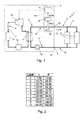
- the delay T represents the delay due to the stratification and parameter P is proportional to a mixing coefficient, which defines the volume percentage of the service fluid 5 in the tank that is affected by the mixing phenomena, at the density of the service fluid 5 in the hydronic circuit 15 expressed in kg/m 3 ad at a storage volume expressed in m 3 that it is wished to simulate, and is inversely proportional to the mass flow of the service fluid expressed in kg/s.
- Figure 2 shows a table in which a series of values are listed that the parameters T and P must assume in order to simulate a corresponding series of tank volume values expressed in L/kW, i.e. expressed in litres with reference to the nominal power of the compressor 12. These values have been determined through experimental tests, applying a method known as the area method, which allows a system to be identified via its response to an input signal, such as a unitary step for example.
- the best compromise between damping the dynamics of the system 1 and the regulating speed of the delivery temperature TDLV is obtained by sizing the filter 22 for intermediate tank volumes, between 4 and 6 L/kW for example, and preferably for a tank volume value equal to 5 L/kW, to which there is a corresponding delay T substantially equal to 32.6 s and a parameter P substantially equal to 70.8 s.
- the diagram of the principle of the refrigerating machine 3 shown in Figure 1 can also generically describe a machine suited to heat the service fluid 5 for the purpose of heating the environments in which the fan coils 2 are placed, for example a refrigerating machine 3 of the type operating as a heat pump.
- the compressor 12 is configured so as to perform the refrigeration cycle in the opposite sense to that previously described, such that the heat exchanger 11 functions as a condenser to transfer heat from the working fluid 7 to the service fluid 5 and the heat exchanger 13 functions as an evaporator.
- the sizing of the filter 22 is virtually independent of the fact of cooling or heating the service fluid 5.
- the control device 19 provided with the filter 22 is also applicable to a refrigerating machine suited to heat the service fluid 5.
- control device 19 for a refrigerating machine 3 is to allow the elimination of the storage tank on the delivery branch 16 of the hydronic circuit 15, whilst still guaranteeing the necessary stability of the air-conditioning system 1 thanks to the presence of the filter 22, which defines a virtual storage tank.
Landscapes
- Engineering & Computer Science (AREA)
- Physics & Mathematics (AREA)
- Mechanical Engineering (AREA)
- Thermal Sciences (AREA)
- General Engineering & Computer Science (AREA)
- Devices That Are Associated With Refrigeration Equipment (AREA)
- Air Conditioning Control Device (AREA)
- Control Of Temperature (AREA)
Claims (5)
- Steuervorrichtung für ein Kühlgerät (3) mit einem Kompressor (12), wobei die Steuereinrichtung (19) aufweist eine Temperatur-Sensoreinrichtung (20), um ein erstes Signal (SDLV) zu liefern, das die Abgabetemperatur (TDLV) eines Betriebsfluids (5) im Ausgang aus dem Kühlgerät (3) repräsentiert, eine Steuereinheit (21), die dazu geeignet ist, den Kompressor (12) gemäß dem ersten Signal (SDLV) ein- und auszuschalten, und eine Signal-Dämpfungseinrichtung (22), um das erste Signal (SDLV) zu empfangen und ein korrespondierendes gedämpftes zweites Signal (SCTRL) zu liefern, das durch ein Dämpfen der Dynamik des ersten Signals (SDLV) erhalten wird und dazu geeignet ist, in den Eingang zur Steuereinheit (21) geführt zu werden, um das Ein- und Ausschalten des Kompressors (12) zu steuern, dadurch gekennzeichnet, dass die Dämpfungseinrichtung ein Filter erster Ordnung (22) mit Verzögerung aufweist, um eine Akkumulation des Betriebsfluids (5) zu simulieren.
- Vorrichtung nach Anspruch 1, in welcher das Filter (22) eine der Laplace-Transformation entsprechende Bereich-Übertragungsfunktion hat, die gegeben wird durch:

wobei T eine Verzögerung zwischen dem ersten Signal (SCLV) im Eingang zum Filter und dem zweiten Signal (SCTRL) im Ausgang vom Filter (22) definiert und P ein Akkumulationsparameter ist, der proportional ist zu einem Speichervolumen des Betriebsfluids (5), das simuliert werden soll, und zu einem Mischkoeffizienten des Betriebsfluids (5) in dem Speichervolumen. - Vorrichtung nach Anspruch 2, in welcher das Filter (22) größenmäßig auf einen Wert des Speichervolumens angepasst ist, um in dem Bereich von 4 bis 6 L/kW zu simulieren.
- Vorrichtung nach Anspruch 2 oder 3, in welcher die Verzögerung (T) zwischen dem ersten Signal (SDLV) und dem zweiten Signal (SCTRL) gleich 32,6 s ist und der Akkumulationsparameter (P) gleich 70,8 s ist.
- Kühlgerät (3) mit einem Kompressor (12) und einer Steuereinrichtung (19) zum Ein- und Ausschalten des Kompressors (12) gemäß einer Messung der Abgabetemperatur (TDLV) eines Betriebsfluids (5) im Ausgang von dem Kühlgerät (3) und dadurch gekennzeichnet, dass die Steuereinrichtung (19) von der Bauart ist, die in einem der Ansprüche 1 bis 4 geltend gemacht wird.
Priority Applications (3)
| Application Number | Priority Date | Filing Date | Title |
|---|---|---|---|
| EP20070425351 EP2000758B1 (de) | 2007-06-04 | 2007-06-04 | Steuervorrichtung für ein Kühlgerät |
| ES07425351T ES2362133T3 (es) | 2007-06-04 | 2007-06-04 | Dispositivo de control para una máquina de refrigeración. |
| DE200760012060 DE602007012060D1 (de) | 2007-06-04 | 2007-06-04 | Steuervorrichtung für ein Kühlgerät |
Applications Claiming Priority (1)
| Application Number | Priority Date | Filing Date | Title |
|---|---|---|---|
| EP20070425351 EP2000758B1 (de) | 2007-06-04 | 2007-06-04 | Steuervorrichtung für ein Kühlgerät |
Publications (2)
| Publication Number | Publication Date |
|---|---|
| EP2000758A1 EP2000758A1 (de) | 2008-12-10 |
| EP2000758B1 true EP2000758B1 (de) | 2011-01-19 |
Family
ID=38657316
Family Applications (1)
| Application Number | Title | Priority Date | Filing Date |
|---|---|---|---|
| EP20070425351 Not-in-force EP2000758B1 (de) | 2007-06-04 | 2007-06-04 | Steuervorrichtung für ein Kühlgerät |
Country Status (3)
| Country | Link |
|---|---|
| EP (1) | EP2000758B1 (de) |
| DE (1) | DE602007012060D1 (de) |
| ES (1) | ES2362133T3 (de) |
Families Citing this family (1)
| Publication number | Priority date | Publication date | Assignee | Title |
|---|---|---|---|---|
| HK1137899A2 (zh) * | 2009-06-05 | 2010-08-06 | Ace Action Limited | 节能装置、空调或制冷系统及空调或制冷系统的控制方法 |
Family Cites Families (4)
| Publication number | Priority date | Publication date | Assignee | Title |
|---|---|---|---|---|
| US4292813A (en) * | 1979-03-08 | 1981-10-06 | Whirlpool Corporation | Adaptive temperature control system |
| JP2696398B2 (ja) * | 1989-06-22 | 1998-01-14 | 株式会社ゼクセル | 車両用空調装置のコンプレッサ制御装置 |
| KR100573770B1 (ko) | 2004-04-24 | 2006-04-25 | 삼성전자주식회사 | 냉장고 및 그 제어방법 |
| BRPI0403128A (pt) * | 2004-08-02 | 2006-03-14 | Multibras Eletrodomesticos Sa | sistema para ajustar a temperatura em um aparelho de refrigeração |
-
2007
- 2007-06-04 ES ES07425351T patent/ES2362133T3/es active Active
- 2007-06-04 DE DE200760012060 patent/DE602007012060D1/de active Active
- 2007-06-04 EP EP20070425351 patent/EP2000758B1/de not_active Not-in-force
Also Published As
| Publication number | Publication date |
|---|---|
| DE602007012060D1 (de) | 2011-03-03 |
| ES2362133T3 (es) | 2011-06-28 |
| EP2000758A1 (de) | 2008-12-10 |
Similar Documents
| Publication | Publication Date | Title |
|---|---|---|
| EP3699514B1 (de) | Systeme und verfahren zur steuerung eines kühlsystems | |
| US11279205B2 (en) | Method for operating a coolant circuit and vehicle air-conditioning system | |
| EP3500805B1 (de) | Systeme und verfahren zur steuerung eines kühlsystems | |
| EP3379178B1 (de) | Kühlmittelkontrollverfahren | |
| EP3587933B1 (de) | Kühlmitteltransfersteuerung in einer mehrfachmodusklimaanlage mit heisswassererzeuger | |
| EP2122276B1 (de) | Freikühlungsbegrenzungssteuerung für klimaanlagen | |
| JP6950191B2 (ja) | 空気調和機 | |
| CN106461300B (zh) | 冷却系统 | |
| US9696077B2 (en) | Dual capillary tube / heat exchanger in combination with cycle priming for reducing charge migration | |
| JP2009031866A (ja) | 流量制御バルブおよび流量制御方法 | |
| US20130213066A1 (en) | Refrigeration arrangement and methods for reducing charge migration | |
| KR920006705A (ko) | 멀티플형 공기조화기 | |
| AU2016257496A1 (en) | An improved temperature control system | |
| CN104422193A (zh) | 制冷、制热蓄液方法及制冷、制热防霜方法和空调系统 | |
| EP3736509B1 (de) | Kühlsystem mit wärmerückgewinnung | |
| CN104101140A (zh) | 冷柜或冰箱及其制冷系统 | |
| EP2000758B1 (de) | Steuervorrichtung für ein Kühlgerät | |
| EP2000754B1 (de) | Verfahren zur Schätzung der Wärmebelastung einer Leitung für eine Betriebsflüssigkeit am Auslass einer Kühlmaschine | |
| EP3674622B1 (de) | Fluidsteuerung für einen fluidkreislauf mit variabler strömung einer einheit in einem hvacr-system | |
| EP3332182B1 (de) | Kühleranlage | |
| JP5181933B2 (ja) | 自動販売機 | |
| CN108027189B (zh) | 用于制冷机的冻结防护系统和方法 | |
| JP2023159767A (ja) | 冷却システム及び水中ビークル | |
| JP2020133998A (ja) | 冷凍装置 | |
| JP2017181001A (ja) | 空気調和装置 |
Legal Events
| Date | Code | Title | Description |
|---|---|---|---|
| PUAI | Public reference made under article 153(3) epc to a published international application that has entered the european phase |
Free format text: ORIGINAL CODE: 0009012 |
|
| AK | Designated contracting states |
Kind code of ref document: A1 Designated state(s): AT BE BG CH CY CZ DE DK EE ES FI FR GB GR HU IE IS IT LI LT LU LV MC MT NL PL PT RO SE SI SK TR |
|
| AX | Request for extension of the european patent |
Extension state: AL BA HR MK RS |
|
| RIN1 | Information on inventor provided before grant (corrected) |
Inventor name: SCODELLARO, ALESSANDRO Inventor name: ALBIERI, MICHELE Inventor name: BODO, CRISTIAN Inventor name: ZEN, ALESSANDRO Inventor name: CECCHINATO, LUCA Inventor name: BEGHI, ALESSANDRO |
|
| 17P | Request for examination filed |
Effective date: 20090608 |
|
| 17Q | First examination report despatched |
Effective date: 20090703 |
|
| AKX | Designation fees paid |
Designated state(s): DE ES FR GB IT |
|
| GRAP | Despatch of communication of intention to grant a patent |
Free format text: ORIGINAL CODE: EPIDOSNIGR1 |
|
| GRAS | Grant fee paid |
Free format text: ORIGINAL CODE: EPIDOSNIGR3 |
|
| GRAA | (expected) grant |
Free format text: ORIGINAL CODE: 0009210 |
|
| AK | Designated contracting states |
Kind code of ref document: B1 Designated state(s): DE ES FR GB IT |
|
| REG | Reference to a national code |
Ref country code: GB Ref legal event code: FG4D |
|
| REF | Corresponds to: |
Ref document number: 602007012060 Country of ref document: DE Date of ref document: 20110303 Kind code of ref document: P |
|
| REG | Reference to a national code |
Ref country code: DE Ref legal event code: R096 Ref document number: 602007012060 Country of ref document: DE Effective date: 20110303 |
|
| REG | Reference to a national code |
Ref country code: ES Ref legal event code: FG2A Ref document number: 2362133 Country of ref document: ES Kind code of ref document: T3 Effective date: 20110628 |
|
| PLBE | No opposition filed within time limit |
Free format text: ORIGINAL CODE: 0009261 |
|
| STAA | Information on the status of an ep patent application or granted ep patent |
Free format text: STATUS: NO OPPOSITION FILED WITHIN TIME LIMIT |
|
| 26N | No opposition filed |
Effective date: 20111020 |
|
| REG | Reference to a national code |
Ref country code: DE Ref legal event code: R097 Ref document number: 602007012060 Country of ref document: DE Effective date: 20111020 |
|
| REG | Reference to a national code |
Ref country code: FR Ref legal event code: PLFP Year of fee payment: 10 |
|
| REG | Reference to a national code |
Ref country code: FR Ref legal event code: PLFP Year of fee payment: 11 |
|
| PGFP | Annual fee paid to national office [announced via postgrant information from national office to epo] |
Ref country code: GB Payment date: 20170630 Year of fee payment: 11 Ref country code: FR Payment date: 20170629 Year of fee payment: 11 |
|
| PGFP | Annual fee paid to national office [announced via postgrant information from national office to epo] |
Ref country code: IT Payment date: 20170609 Year of fee payment: 11 |
|
| PGFP | Annual fee paid to national office [announced via postgrant information from national office to epo] |
Ref country code: ES Payment date: 20170724 Year of fee payment: 11 Ref country code: DE Payment date: 20170831 Year of fee payment: 11 |
|
| REG | Reference to a national code |
Ref country code: DE Ref legal event code: R119 Ref document number: 602007012060 Country of ref document: DE |
|
| GBPC | Gb: european patent ceased through non-payment of renewal fee |
Effective date: 20180604 |
|
| PG25 | Lapsed in a contracting state [announced via postgrant information from national office to epo] |
Ref country code: IT Free format text: LAPSE BECAUSE OF NON-PAYMENT OF DUE FEES Effective date: 20180604 Ref country code: DE Free format text: LAPSE BECAUSE OF NON-PAYMENT OF DUE FEES Effective date: 20190101 Ref country code: GB Free format text: LAPSE BECAUSE OF NON-PAYMENT OF DUE FEES Effective date: 20180604 Ref country code: FR Free format text: LAPSE BECAUSE OF NON-PAYMENT OF DUE FEES Effective date: 20180630 |
|
| REG | Reference to a national code |
Ref country code: ES Ref legal event code: FD2A Effective date: 20190916 |
|
| PG25 | Lapsed in a contracting state [announced via postgrant information from national office to epo] |
Ref country code: ES Free format text: LAPSE BECAUSE OF NON-PAYMENT OF DUE FEES Effective date: 20180605 |