EP2000698A2 - Amortisseur de vibrations de torsion - Google Patents
Amortisseur de vibrations de torsion Download PDFInfo
- Publication number
- EP2000698A2 EP2000698A2 EP08005263A EP08005263A EP2000698A2 EP 2000698 A2 EP2000698 A2 EP 2000698A2 EP 08005263 A EP08005263 A EP 08005263A EP 08005263 A EP08005263 A EP 08005263A EP 2000698 A2 EP2000698 A2 EP 2000698A2
- Authority
- EP
- European Patent Office
- Prior art keywords
- torsional vibration
- vibration damper
- primary side
- secondary side
- spring
- Prior art date
- Legal status (The legal status is an assumption and is not a legal conclusion. Google has not performed a legal analysis and makes no representation as to the accuracy of the status listed.)
- Granted
Links
- 230000007935 neutral effect Effects 0.000 claims abstract description 17
- 230000000750 progressive effect Effects 0.000 claims abstract description 11
- 230000009471 action Effects 0.000 claims abstract description 8
- 230000008878 coupling Effects 0.000 claims description 31
- 238000010168 coupling process Methods 0.000 claims description 31
- 238000005859 coupling reaction Methods 0.000 claims description 31
- 230000000712 assembly Effects 0.000 claims description 21
- 238000000429 assembly Methods 0.000 claims description 21
- 239000012530 fluid Substances 0.000 claims description 20
- 230000005540 biological transmission Effects 0.000 claims description 15
- 238000006243 chemical reaction Methods 0.000 claims description 8
- 238000012546 transfer Methods 0.000 claims description 7
- 230000000694 effects Effects 0.000 claims description 5
- 230000036316 preload Effects 0.000 claims description 2
- 238000013016 damping Methods 0.000 abstract description 9
- 230000006835 compression Effects 0.000 description 15
- 238000007906 compression Methods 0.000 description 15
- 238000010586 diagram Methods 0.000 description 5
- 238000006073 displacement reaction Methods 0.000 description 5
- 230000004913 activation Effects 0.000 description 4
- 238000010276 construction Methods 0.000 description 4
- 230000007423 decrease Effects 0.000 description 2
- 230000003247 decreasing effect Effects 0.000 description 2
- 230000010355 oscillation Effects 0.000 description 2
- 230000000630 rising effect Effects 0.000 description 2
- 230000000454 anti-cipatory effect Effects 0.000 description 1
- 230000001174 ascending effect Effects 0.000 description 1
- 238000002485 combustion reaction Methods 0.000 description 1
- 230000009849 deactivation Effects 0.000 description 1
- 238000013461 design Methods 0.000 description 1
- 238000011161 development Methods 0.000 description 1
- 238000004519 manufacturing process Methods 0.000 description 1
- 239000007769 metal material Substances 0.000 description 1
- 238000000034 method Methods 0.000 description 1
- 230000004048 modification Effects 0.000 description 1
- 238000012986 modification Methods 0.000 description 1
- 230000021715 photosynthesis, light harvesting Effects 0.000 description 1
- 230000008569 process Effects 0.000 description 1
- 230000000284 resting effect Effects 0.000 description 1
- 238000007789 sealing Methods 0.000 description 1
- 238000003466 welding Methods 0.000 description 1
Images


Classifications
-
- F—MECHANICAL ENGINEERING; LIGHTING; HEATING; WEAPONS; BLASTING
- F16—ENGINEERING ELEMENTS AND UNITS; GENERAL MEASURES FOR PRODUCING AND MAINTAINING EFFECTIVE FUNCTIONING OF MACHINES OR INSTALLATIONS; THERMAL INSULATION IN GENERAL
- F16F—SPRINGS; SHOCK-ABSORBERS; MEANS FOR DAMPING VIBRATION
- F16F15/00—Suppression of vibrations in systems; Means or arrangements for avoiding or reducing out-of-balance forces, e.g. due to motion
- F16F15/10—Suppression of vibrations in rotating systems by making use of members moving with the system
- F16F15/12—Suppression of vibrations in rotating systems by making use of members moving with the system using elastic members or friction-damping members, e.g. between a rotating shaft and a gyratory mass mounted thereon
- F16F15/131—Suppression of vibrations in rotating systems by making use of members moving with the system using elastic members or friction-damping members, e.g. between a rotating shaft and a gyratory mass mounted thereon the rotating system comprising two or more gyratory masses
- F16F15/133—Suppression of vibrations in rotating systems by making use of members moving with the system using elastic members or friction-damping members, e.g. between a rotating shaft and a gyratory mass mounted thereon the rotating system comprising two or more gyratory masses using springs as elastic members, e.g. metallic springs
- F16F15/134—Wound springs
- F16F15/13469—Combinations of dampers, e.g. with multiple plates, multiple spring sets, i.e. complex configurations
Definitions
- the present invention relates to a torsional vibration damper comprising a primary side and a against the action of a damper assembly, starting from a neutral relative rotational position about an axis of rotation relative to the primary side rotatable secondary side.
- the damper arrangement generally comprises a plurality of helical compression springs installed under prestress between the primary side and the secondary side. Upon deflection of the primary side relative to the secondary side, starting from the neutral relative rotational position also assumed in the torque-free state, these helical compression springs are compressed and thus generate a restoring force increasing with increasing deflection.
- Such constructed with helical compression springs damper assemblies thus have an increasing course of the damper characteristic, as he, for example, in the Fig. 7 is illustrated by the characteristic K 1 .
- the characteristic curve K 1 also increases in a straight line, wherein the lower left region can represent, for example, the initial state of the neutral relative rotational position already afflicted with a specific pretensioning force.
- the torsional vibration damper constructed in accordance with the invention it becomes possible to operate the torsional vibration damper in a comparatively flat overall characteristic range through the optional coupling or decoupling of the second damper unit, which has a degressive characteristic curve, through the superposition with the progressive characteristic curve of the first damper unit.
- a progressive course of a damper characteristic is characterized in that with increasing load of a respective damper unit, the reaction force generated by the damper unit increases, for example, increases linearly, as based on the characteristic K 1 illustrated for the example of a helical compression spring or on the basis of the characteristic K 2 in the case of several stepped effect becoming helical compression springs.
- a progressive characteristic curve thus generally means a characteristic curve increasing over the load path or compression path, whereby this course can also be progressively ascending, that is to say may proceed with increasing gradient, or may increase degressively, that is, may increase with decreasing slope.
- a degressive course of a damper characteristic is characterized in that with increasing load, that is to say with rotation of the primary side with respect to the secondary side further away from the neutral relative rotational position, the reaction force generated in a respective damper unit decreases, for example decreases linearly or with a curved course.
- degressive generally means a sloping course of a damper characteristic curve over the load path or compression path, whereby a progressive drop may also be present here, ie a drop with increasing slope or a degressive drop may be provided, ie a drop decreasing slope.
- the above-mentioned stiffness of a damper unit or the damper arrangement essentially characterizes the slope of a respective considered characteristic curve. In the context of the present invention, a comparatively large slope therefore means a high degree of rigidity, while a comparatively flat characteristic curve in the sense of the present invention is to be interpreted as low rigidity.
- the progressive characteristic curve of the first damper unit can be obtained in a simple manner by the fact that the first damper unit comprises at least one helical spring or gas spring which is compressible in the direction of relative rotation of the primary side with respect to the secondary side in the direction away from the neutral relative rotary position.
- the degressive characteristic curve of the second damper unit can be obtained, for example, by virtue of the fact that it comprises at least one plate spring which deforms in the direction of the neutral relative rotational position relative to the secondary side in the case of relative rotation of the primary side.
- the second damper unit at least one disc spring assembly with a loading at least one plate spring first part and the at least one The second plate spring loaded second part, wherein the at least one plate spring is held biased on the first part or the second part, wherein further preferably can be provided that the at least one plate spring is held biased at the one part of the first part and second part, in that, starting from the pretension state, further loading of the at least one disk spring leads to a reduced reaction force of the at least one disk spring.
- the at least one disc spring assembly may comprise at least two biased cup springs.
- the construction of the at least one disc spring assembly may, for example, be such that the first part loads the at least one disc spring radially outward and the second part loads the at least one disc spring radially inward.
- the structure may be such that the first part at least a first plate spring radially outwardly loaded, that the second part at least a second plate spring radially outwardly loaded and that the at least one first plate spring and the at least one second plate spring radially inwardly with respect to each other are supported.
- the second damper unit at least one group of serially comprises acting disc spring assemblies.
- connection or disconnection of the second damper unit in the torque transmission path or from the torque transmission path can be obtained in that the second damper unit has a first coupling region substantially non-rotatably coupled to one side of the primary side and the secondary side and one with the other side of the primary side and Secondary side optionally in torque transfer coupling can be brought second coupling region.
- the second coupling region is assigned a first clamping arrangement on the other side of the primary side and secondary side, wherein the torque transfer coupling can be produced and canceled by the first clamping arrangement.
- This first clamping arrangement can thus be effective in the manner of a friction clutch to ensure by Reibkraft gleich a torque transmission between the primary side and the secondary side and the second damper unit.
- the construction may preferably be such that the first clamping arrangement comprises at least one first clamping member displaceable by pressurized fluid for producing / canceling the torque-transmitting coupling.
- an optionally activatable and deactivatable friction device is provided for generating a friction effect between the primary side and the secondary side.
- the optional activation or deactivation of the friction device can take place in that the friction device has a second clamping arrangement with at least one by Druckfluidbeaufschlagung for production / repeal associated with the friction action displaceable second clamping member.
- the second clamping arrangement is provided on the other side of the primary side and the secondary side.
- the other side of the primary side and secondary side is assigned a rotary feedthrough for the supply / removal of pressurized fluid.
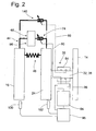
- the Fig. 1 and 2 show in longitudinal section or in circuit diagram-like representation of the structure of a generally designated 10 torsional vibration damper for the drive train of a vehicle.
- This torsional vibration damper 10 serves, for example, to transmit a torque between a drive member 12, for example, a crankshaft of an internal combustion engine, and a flywheel 14 of a friction clutch or the like.
- the torsional vibration damper 10 comprises a primary side 16 with two cover disk elements 18, 20, which are formed, for example, from sheet metal material. These are connected to one another radially externally, for example by welding.
- the cover disk element 18 and thus the primary side 16 may be fixedly connected to the drive member 12 for common rotation about a rotation axis A via a drive plate 22, which may be formed in particular axially flexible.
- a secondary side 24 of the torsional vibration damper 10 comprises a central disk element 26 which engages radially outwardly between the two cover disk elements 18, 20. Radially inside the central disk element 26 is rotatably coupled using a clamping screw 28 and a clamping plate 30 with a first rotor part 32 of the secondary side 24. Via a bearing 34, the cover disk element 18 of the primary side 16 is rotatably mounted radially and, if necessary, also axially with respect to the first rotor part 32.
- a second rotor part 38 of a rotary feedthrough 36 which is explained below, is non-rotatably coupled to the first rotor part 32.
- the flywheel 14 is rotatably connected via a clamping screw 40 and a clamping element 42.
- a clamping screw 40 and a clamping element 42 it can be seen that between the central disk element 26 and the flywheel 14 is a substantially rotationally fixed connection.
- a generally designated 44 damper assembly is provided for torque transmission between the primary side 16 and the secondary side 24.
- the damper unit 46 is formed, for example, with a plurality of circumferentially successive and possibly also radially nested coil springs or helical compression springs 50. These are based in the circumferential direction in a conventional manner on respective support areas of the cover disk elements 18, 20 and central disk element 26 from, so are held for example in so-called spring windows under bias. Relative rotation of the cover disk elements 18, 20 with respect to the central disk element 24, starting from a neutral relative rotational position, thus takes place against the restoring force generated by the coil springs 50.
- This restoring force is progressive, So increases with increasing rotational deflection of the primary side 16 with respect to the secondary side 24, for example, in a linear or stepped linear manner, as based on the characteristics K 1 and K 2 already with reference to the Fig. 7 explained.
- the coil springs 50 can be supported radially outward over so-called sliding shoes 52 in order to obtain a minimization of the frictional forces.
- the second damper unit 48 comprises a first coupling region 54 constructed in the manner of a central disk element 64. The latter is coupled in a rotationally fixed manner by toothing engagement with the cover disk element 20 and thus the primary side 16 of the torsional vibration damper 10 and is therefore also assigned to the primary side 16 in terms of mass.
- a second coupling region 60 of the second damper unit 48 which is constructed with two cover disk elements 56, 58, comprises a radially inner clamping washer 62, which will be firmly connected to the two cover disk elements 56, 58 by riveting or the like and surrounds the first rotor part 32 in a ring-like manner. is therefore in principle rotatable with respect to this about the axis of rotation A.
- an abutment ring 70 is connected to the first rotor part 32 in the axial direction supported by a securing ring 68.
- This can for example be rotatably coupled to the first rotor member 32, for example by toothing engagement.
- On the other axial side of the clamping plate 62 is a clamping ring 72 a generally with 74 designated first clamping arrangement provided.
- This first clamping arrangement 74 comprises, for example, integrally formed with the first rotor part 32 a ring cylinder 76, in which in the direction of the axis of rotation A slidably an annular piston 78 is received.
- pressurized fluid for example compressed air or pressurized oil
- pressurized fluid can be supplied to or removed from the annular cylinder 76 via the rotary leadthrough 36.
- pressurized fluid for example compressed air or pressurized oil
- the second rotor part 38 which also forms the rotating part of the rotary feedthrough 36, leading to the annular cylinder 76 Fuidkanäle 80, 82 are formed.
- Fuidkanäle 80, 82 are formed in a radially outer, non-rotating part 84 of the rotary leadthrough 36 are in association with the channels 80, 82 further channels 86, 88 are provided, via which a supply or discharge of pressurized fluid can take place.
- a pressurized fluid source for example a compressor or an oil pump, or a pressure fluid also receiving reservoir in the Fig. 1 are not shown.
- This source of pressurized fluid is shown schematically in FIG Fig. 2 recognizable and designated there by 94.
- a valve arrangement 96 which frees or blocks the various flow paths to and from the annular cylinder 76, the pressure fluid can be conducted into or withdrawn from the region of the secondary side 24.
- a drive device 98 which controls the pressure fluid source 94 and the valve assembly 96 to selectively by pressurized fluid supply or
- the drive device 98 receives, inter alia, input signals from rotary sensors 100 and 102, which provide information about the rotational position of the primary side 16 and the secondary side 24. From this information, the drive device 98 can, inter alia, determine information about the relative rotational position or also the relative rotational speed of the primary side 16 with respect to the secondary side 24 and then actuate the valve arrangement 96 or the pressure fluid source 94 based on this information in order to activate the second damper unit 48 or disable.
- a coupling of the second coupling region 60 to the secondary side 24 can take place with a corresponding displacement of the annular piston 78, so that optionally the second damper unit 48 is switched into the torque transmission path between the primary side 16 and the secondary side 24 or out of this Torque transmission can be switched off.
- the second damper unit 48 acts in parallel with the first damper unit 46.
- the 3 and 4 show the construction of a Belleville spring assembly 66 as previously described with reference to FIGS Fig. 1 already indicated.
- the disc spring assembly 66 shown in the unloaded state comprises two annular parts 104, 106.
- the two parts 104, 106 have radially inward respective interengaging cylindrical lugs 108, 110, which also with respect to a defined axial guidance or displaceability of the two parts 104, 106 ensure each other.
- the plate spring 112 is radially outwardly supported on a support portion 116 of the first part 104.
- the plate spring 114 is radially outward on the both disc springs 112, 114 radially outwardly cross-biasing holding portions 118 of the first part 104 axially supported.
- a ring-like intermediate element 120 is loaded by both disc springs 112, 114 due to the fact that the two plate springs 112, 114 are held biased on the first part 104.
- FIGS. 5 and 6 12 shows a group 124 of the disk spring assemblies 66 explained above, which are provided in respective spring windows 126 of the central disk element 64 and the cover disk elements 56, 58 of the first coupling region 54 and of the second coupling region 60, respectively, in a manner known per se.
- spring windows 126 conventionally constructed torsional vibration dampers
- the circumferentially extending helical compression springs are arranged.
- the groups 124 of disk spring assemblies 66 are provided in these spring windows 126, of which, of course, a plurality of successively are provided in the circumferential direction about the rotation axis A.
- these groups 124 comprise, for example, three disc spring assemblies 66.
- disc spring assemblies 66 can be accommodated in the spring windows 126 in an even more prestressed state in addition to the prestressing of the disc springs 112, 114 already mentioned above so they are not in the same. loaded state on respective control edges 128, 130 of the spring window 126 support.
- a relative rotation of the primary side 16 with respect to the secondary side 24 causes the spring windows in the central disk element 64 and the cover disk elements 56, 58 to shift in the circumferential direction with respect to each other.
- this is illustrated by means of the spring window 126 of the central disk element 64 and of the spring window 126 ', which is shown by the solid line, for example of the cover disk element 56.
- the disc spring assemblies 66 are charged and the disc springs 112, 114 additionally tensioned, as in Fig. 3b) is shown.
- the characteristic curve K 3 thus reflects the reaction force generated by a disc spring when loaded. It can be seen that initially starting from the in Fig. 8 On the left side shown unloaded and slightly umbrella-like preformed state, for example, the plate spring 112 at a deformation in the direction of flattening first in a rising branch K 3a, a steep increase in the spring reaction force occurs, until a local maximum M 1 is reached. It then follows a sloping, so degressive area K 3b , in which the plate spring 112 on their perfect Flattening going out in the relaxed state opposite direction is deformed. Further deformation leads to a local minimum M 2 . On the basis of this local minimum M 2 , a further deformation of the plate spring 112 then leads to an increase in a region K 3c of the characteristic curve K 3 .
- the present invention uses the degressive part K 3b of the characteristic curve K 3 of a plate spring, for example in the in Fig. 8
- Area B marked in this area B is the pretensioning area, ie the compression path that plate spring 112 or other disk springs undergo when installed in the respective cup spring assemblies 66.
- a respective plate spring is then located at the adjoining area of the characteristic curve sections K 3a and K 3b .
- the disc springs can then be on the characteristic in the adjoining region of the sections K 3b and K 3c . It is thus ensured that in the second damper unit 48 only the degressive, approximately linear, but slightly curved section K 3b of the characteristic curve is used.
- Fig. 9 Basically, one recognizes the characteristic curve K 1 on the basis of the coarsely dashed line, which proceeds to the right, that is to say in the direction away from the neutral relative rotational position, progressively or linearly increases. Depending on the extent to which the primary side 16 and the secondary side 24 are rotated with respect to each other, therefore, a reaction force generated on the basis of this characteristic curve K 1 is generated by the coil spring 50, through which the primary side 16 and the secondary side 24 toward the neutral Relative rotational position are reloaded.
- the system If the system enters a vibration-critical state, for example because a resonant region is passed through, it can be switched on or activation of the second damper unit 48 a significantly lower rigidity of the torsional vibration damper 10 can be obtained.
- a significantly lower rigidity of the torsional vibration damper 10 can be obtained.
- the range B It is assumed here, for example, that in the relative rotational state Z 1 , which is detected due to the outputs of the sensors 100, 102, the pressure of the pressurized fluid in the annular cylinder 76 is increased and thus the first clamping assembly 74 is brought into its engaged state.
- Fig. 9 it is of course possible to connect the second damper unit 48 in different working areas of the first damper unit 46. If, for example, a larger torque is to be transmitted via the torsional vibration damper 10 in principle, this means that the primary side 16 and the secondary side 24 will be relatively strongly rotated with respect to each other. If torque fluctuations occur in this state, an oscillation will not take place around the neutral relative rotational position, but will take place in a region which is comparatively far removed from the neutral relative rotational position. In order to utilize the advantages of the invention in such a condition that can be determined by the outputs of the sensors 100, 102 as well can, will, like this Fig.
- the second damper unit 48 then activated, that is turned on in the torque transmission path, if this is necessary in view of the detected state. It is therefore also possible in an area B ', which is displaced towards significantly larger torques to be transmitted, to receive an overall characteristic curve G' by connecting the second damper unit 48, which ensures suitable damping in this torque range.
- the Fig. 14 shows the time course of the torque M to be transmitted via a torsional vibration damper 10 on the basis of several oscillation regions having and of course only principally the torque curve representing curve D. It can be seen that substantially over the entire time period, the two damper units 46 and 48 respectively cooperate, so the second damper unit 48 is permanently switched on. As a result, an overall characteristic G which is composed of the characteristic curve K 1 in the respective torque or relative rotational angle range and the characteristic K 3b to be superimposed is effective for each time range.
- the first clamping arrangement 74 can be at least slightly released. The consequence of this is that, on the one hand, the second damper unit 48 can relax, while on the other hand, a larger proportion of torque is taken over by the first damper unit 46. If the first clamping arrangement 74 is then brought back into its closed state, then it is again possible to work in one of the areas B, but with an increased torque to be transmitted. Taking into account the sensor signals of the sensors 100, 102, the center areas Mi of these areas B, which are located in Fig.
- FIG. 10a) and 10b) an alternative embodiment of a disc spring assembly 66a is shown.
- the first part 104a has radially outward a support region 116a, on which the plate spring 112a is supported radially outward. In its radially inner region, the first part 104a has a preload holding region 118a, which ensures that the disc spring 112a is kept pretensioned to a desired extent.
- the second part 106a is located radially inside the first part 104a and loaded with its support portion 122a, the plate spring 112a radially inward. The loaded condition is in Fig. 10b) shown.
- Fig. 11 one recognizes a development of this embodiment.
- two disc springs 112a, 114a are provided in the first part 104a, which are stacked, so resting on one another, are arranged. It is of course possible to use more than two disc springs here.
- Fig. 12 is a to be arranged in respective spring windows group 124a of the in the Fig. 10 or 11 disc spring assemblies 66a shown recognizable. It can be seen that in each case two of the disc spring assemblies 66a are placed with their second parts 106a against each other, so that in a respective pair the disc springs 112a are arranged opposite to each other.
- Disposed on the two outer sides of the two pairs of disc spring assemblies 66a are disk-like loading elements 130a, 132a, which act on the respective first parts 104a of the respective disc spring assemblies 66a positioned at the ends of the group 124a. These then transmit the force to the second parts 106a via their disk springs 112a and from these to the second parts 106a of the respective other disk spring assemblies 66a of a respective pair. These other disc spring assemblies 66a are supported by their first parts 104a on an annular transmission element 134a.
- an annular transmission element 134a is supported by their first parts 104a on an annular transmission element 134a.
- Fig. 13 is a further education of in Fig. 1 shown torsional vibration damper 10 shown.
- Torsional vibration damper 10 of Fig. 13 Torsional vibration damper shown basically corresponds to the above with reference to the Fig. 1 described, so that reference can be made to the relevant statements.
- the torsional vibration damper 10 of Fig. 13 additionally has a friction device 140, which can selectively act between the primary side 16 and the secondary side 24.
- the friction device 140 has a friction disk 142 connected to the primary side, in particular the cover disk element 20, which can be clamped by means of a second clamping arrangement 144 provided on the secondary side 24 and thus can also be frictionally coupled to the secondary side 24.
- the ring cylinder 76 is not formed as a cylinder passing through in the circumferential direction, but has a plurality of cylinder chambers 146, 148 arranged sequentially in the circumferential direction.
- pistons 150 slidably received
- pistons 152 are slidably received.
- the arrangement may, for example, be such that the cylinder chambers 146 and 148 are provided alternately.
- the pistons 150 of the cylinder chambers 146 which in their entirety thus essentially provide the first clamping arrangement 74, act upon the clamping ring 72 and can thus activate or deactivate the second damper unit 48 when the loading is released.
- the pistons 152 of the second clamping arrangement 144 act upon a further clamping ring 154 in order to move it in the direction of a further abutment ring 156.
- This further abutment ring 156 is axially locked, for example by a locking ring 158 on the outside of the annular cylinder 76.
- Upon displacement of the clamping ring 154 on the abutment ring 156 to the friction plate 142 is clamped with its radially inner region between the two rings 156, 154 and thus generates a friction effect.
- the friction device 140 acts both parallel to the first damper unit 46, as well as parallel to the second damper unit 48 and can be independently activated or deactivated, whether the second damper unit 48 is active.
- the supply of the cylinder chambers 146, 148 with the pressurized fluid via the rotary leadthrough 36 can be supplied via the channel 80 in the second rotor part 38 and the channel 92 in the non-rotating part 84 of the rotary feedthrough 36, while the cylinder chambers 148 via the channel 86 in the second rotor part 38 and the channel 88 in the non-rotating part 84 can be supplied.
- the second Damping unit 48 selectively switch on or off, but the connection process or shutdown can be done in a controlled or controlled manner so that no sudden connection or disconnection of the second damper unit 48 auftitt, but especially when switching off by gradually lowering the clamping force for the second coupling region 60 a relaxation impact of the disc spring units 66 and 66a can be avoided.
- the switching on and off of the second damper unit 48 and also the friction device 140 can, as already explained above, take place in consideration of the signals supplied by the sensors 100 and 102, which ultimately characterize the relative movement and the relative rotational state between the primary side 16 and the secondary side 24 , Further, it is of course possible by the coupling of the drive device 98 to a CAN bus of a vehicle to learn information about the general driving condition, in particular via the accelerator pedal operation in order to obtain early knowledge about upcoming torque changes. In this way, anticipatory activation of the second damper unit 48 or / and the friction device 140 can already be provided.
- the first damper unit 46 can also be embodied in a different manner, wherein there is great freedom of variation, for example with regard to the selection and arrangement of the coil springs 50.
- the first damper unit 46 can also operate with a plurality of gas springs each having a compressible gas volume loaded by an incompressible fluid contained in displacement chambers when the primary side 16 and the secondary side 24 rotate relative to each other.
Landscapes
- Engineering & Computer Science (AREA)
- General Engineering & Computer Science (AREA)
- Physics & Mathematics (AREA)
- Acoustics & Sound (AREA)
- Aviation & Aerospace Engineering (AREA)
- Mechanical Engineering (AREA)
- Mechanical Operated Clutches (AREA)
Applications Claiming Priority (1)
| Application Number | Priority Date | Filing Date | Title |
|---|---|---|---|
| DE200710026429 DE102007026429A1 (de) | 2007-06-06 | 2007-06-06 | Torsionsschwingungsdämpfer |
Publications (3)
| Publication Number | Publication Date |
|---|---|
| EP2000698A2 true EP2000698A2 (fr) | 2008-12-10 |
| EP2000698A3 EP2000698A3 (fr) | 2010-12-22 |
| EP2000698B1 EP2000698B1 (fr) | 2012-05-16 |
Family
ID=39720538
Family Applications (1)
| Application Number | Title | Priority Date | Filing Date |
|---|---|---|---|
| EP20080005263 Not-in-force EP2000698B1 (fr) | 2007-06-06 | 2008-03-20 | Amortisseur de vibrations de torsion |
Country Status (2)
| Country | Link |
|---|---|
| EP (1) | EP2000698B1 (fr) |
| DE (1) | DE102007026429A1 (fr) |
Cited By (4)
| Publication number | Priority date | Publication date | Assignee | Title |
|---|---|---|---|---|
| FR3023598A1 (fr) * | 2014-07-11 | 2016-01-15 | Valeo Embrayages | Dispositif de transmission de couple pour un vehicule automobile |
| WO2019122709A1 (fr) * | 2017-12-21 | 2019-06-27 | Valeo Embrayages | Dispositif de transmission de couple |
| WO2019122638A1 (fr) * | 2017-12-21 | 2019-06-27 | Valeo Embrayages | Dispositif de transmission de couple |
| WO2019122702A1 (fr) * | 2017-12-21 | 2019-06-27 | Valeo Embrayages | Dispositif de transmission de couple |
Families Citing this family (1)
| Publication number | Priority date | Publication date | Assignee | Title |
|---|---|---|---|---|
| DE102012221269A1 (de) | 2011-12-14 | 2013-06-20 | Schaeffler Technologies AG & Co. KG | Drehmomentübertragungseinrichtung |
Citations (1)
| Publication number | Priority date | Publication date | Assignee | Title |
|---|---|---|---|---|
| EP1566566A1 (fr) | 2004-02-18 | 2005-08-24 | LuK Lamellen und Kupplungsbau Beteiligungs KG | Amortisseur de vibrations de torsion |
Family Cites Families (4)
| Publication number | Priority date | Publication date | Assignee | Title |
|---|---|---|---|---|
| DE3306281A1 (de) * | 1983-02-23 | 1984-08-23 | Fichtel & Sachs Ag, 8720 Schweinfurt | Torsionsschwingungsdaempfer mit geknickter federkennlinie fuer die reibkrafterzeugung |
| RU2166679C2 (ru) * | 1993-05-26 | 2001-05-10 | Лук Ламеллен унд Купплюнгсбау ГмбХ | Фрикционное сцепление |
| WO2006053525A1 (fr) * | 2004-11-20 | 2006-05-26 | Luk Lamellen Und Kupplungsbau Beteiligungs Kg | Amortisseur de vibrations de torsion |
| DE102008003988A1 (de) * | 2007-01-31 | 2008-08-07 | Luk Lamellen Und Kupplungsbau Beteiligungs Kg | Torsionsschwingungsdämpfer |
-
2007
- 2007-06-06 DE DE200710026429 patent/DE102007026429A1/de not_active Withdrawn
-
2008
- 2008-03-20 EP EP20080005263 patent/EP2000698B1/fr not_active Not-in-force
Patent Citations (1)
| Publication number | Priority date | Publication date | Assignee | Title |
|---|---|---|---|---|
| EP1566566A1 (fr) | 2004-02-18 | 2005-08-24 | LuK Lamellen und Kupplungsbau Beteiligungs KG | Amortisseur de vibrations de torsion |
Cited By (7)
| Publication number | Priority date | Publication date | Assignee | Title |
|---|---|---|---|---|
| FR3023598A1 (fr) * | 2014-07-11 | 2016-01-15 | Valeo Embrayages | Dispositif de transmission de couple pour un vehicule automobile |
| WO2019122709A1 (fr) * | 2017-12-21 | 2019-06-27 | Valeo Embrayages | Dispositif de transmission de couple |
| WO2019122638A1 (fr) * | 2017-12-21 | 2019-06-27 | Valeo Embrayages | Dispositif de transmission de couple |
| WO2019122702A1 (fr) * | 2017-12-21 | 2019-06-27 | Valeo Embrayages | Dispositif de transmission de couple |
| FR3075904A1 (fr) * | 2017-12-21 | 2019-06-28 | Valeo Embrayages | Dispositif de transmission de couple |
| FR3075907A1 (fr) * | 2017-12-21 | 2019-06-28 | Valeo Embrayages | Dispositif de transmission de couple |
| FR3075903A1 (fr) * | 2017-12-21 | 2019-06-28 | Valeo Embrayages | Dispositif de transmission de couple |
Also Published As
| Publication number | Publication date |
|---|---|
| EP2000698A3 (fr) | 2010-12-22 |
| EP2000698B1 (fr) | 2012-05-16 |
| DE102007026429A1 (de) | 2008-12-11 |
Similar Documents
| Publication | Publication Date | Title |
|---|---|---|
| DE102010051447A1 (de) | Kupplungseinrichtung | |
| WO2009146673A1 (fr) | Amortisseur de vibrations de torsion avec pendule à force centrifuge | |
| DE102010051446A1 (de) | Kupplungsvorrichtung | |
| EP2212587B1 (fr) | Dispositif d'accouplement hydrodynamique | |
| EP2000698B1 (fr) | Amortisseur de vibrations de torsion | |
| DE102019115758A1 (de) | Reibscheibe mit einer Rotationsachse für eine Reibkupplung | |
| DE19901043A1 (de) | Kupplungsscheibe für eine Kraftfahrzeug-Reibungskupplung | |
| DE102014211884A1 (de) | Blattfeder für ein Mehrscheibenreibpaket und Mehrscheibenreibpaket für eine Reibkupplung | |
| EP1302687B1 (fr) | Dispositif à embrayages multiples | |
| DE112011101594T5 (de) | Dämpfungsmechanismus | |
| EP3286446B1 (fr) | Système d'embrayage | |
| DE10018955B4 (de) | Antriebssystem | |
| DE102011086927A1 (de) | Torsionsdämpfervorrichtung und Drehmomentübertragungsvorrichtung für ein Kraftfahrzeug | |
| DE102019115750A1 (de) | Hybridanordnung mit Torsionsschwingungsdämpfer | |
| DE102012220441A1 (de) | Lamelle für eine Doppelkupplung mit Fliehkraftpendel | |
| DE10241027A1 (de) | Mehrfach-Kupplungsanordnung | |
| EP3405695A1 (fr) | Ensemble d'amortissement de vibrations de torsion pour transmission de véhicule | |
| DE102014203198A1 (de) | Reibungskupplung | |
| DE102019128038A1 (de) | Drehschwingungsdämpfer | |
| DE102015200392A1 (de) | Federeinheit für eine Reibkupplung | |
| DE102006044218A1 (de) | Kupplungssystem mit besonderem Ausgleichsraum | |
| EP1647729A2 (fr) | Dispositif d'embrayages pour embrayages multiples | |
| DE10066436B4 (de) | Schwingungsdämpfersystem | |
| DE102017204558A1 (de) | Torsionsschwingungsdämpfer | |
| DE102011017651A1 (de) | Drehschwingungsdämpfer, insbesondere für den Antriebsstrang eines Fahrzeugs |
Legal Events
| Date | Code | Title | Description |
|---|---|---|---|
| PUAI | Public reference made under article 153(3) epc to a published international application that has entered the european phase |
Free format text: ORIGINAL CODE: 0009012 |
|
| AK | Designated contracting states |
Kind code of ref document: A2 Designated state(s): AT BE BG CH CY CZ DE DK EE ES FI FR GB GR HR HU IE IS IT LI LT LU LV MC MT NL NO PL PT RO SE SI SK TR |
|
| AX | Request for extension of the european patent |
Extension state: AL BA MK RS |
|
| PUAL | Search report despatched |
Free format text: ORIGINAL CODE: 0009013 |
|
| AK | Designated contracting states |
Kind code of ref document: A3 Designated state(s): AT BE BG CH CY CZ DE DK EE ES FI FR GB GR HR HU IE IS IT LI LT LU LV MC MT NL NO PL PT RO SE SI SK TR |
|
| AX | Request for extension of the european patent |
Extension state: AL BA MK RS |
|
| 17P | Request for examination filed |
Effective date: 20110526 |
|
| AKX | Designation fees paid |
Designated state(s): AT BE BG CH CY CZ DE DK EE ES FI FR GB GR HR HU IE IS IT LI LT LU LV MC MT NL NO PL PT RO SE SI SK TR |
|
| REG | Reference to a national code |
Ref country code: DE Ref legal event code: R079 Ref document number: 502008007174 Country of ref document: DE Free format text: PREVIOUS MAIN CLASS: F16F0015131000 Ipc: F16F0015134000 |
|
| GRAP | Despatch of communication of intention to grant a patent |
Free format text: ORIGINAL CODE: EPIDOSNIGR1 |
|
| RIC1 | Information provided on ipc code assigned before grant |
Ipc: F16F 15/131 20060101ALI20111124BHEP Ipc: F16F 15/134 20060101AFI20111124BHEP |
|
| GRAS | Grant fee paid |
Free format text: ORIGINAL CODE: EPIDOSNIGR3 |
|
| GRAA | (expected) grant |
Free format text: ORIGINAL CODE: 0009210 |
|
| AK | Designated contracting states |
Kind code of ref document: B1 Designated state(s): AT BE BG CH CY CZ DE DK EE ES FI FR GB GR HR HU IE IS IT LI LT LU LV MC MT NL NO PL PT RO SE SI SK TR |
|
| REG | Reference to a national code |
Ref country code: GB Ref legal event code: FG4D Free format text: NOT ENGLISH |
|
| REG | Reference to a national code |
Ref country code: CH Ref legal event code: EP |
|
| REG | Reference to a national code |
Ref country code: AT Ref legal event code: REF Ref document number: 558257 Country of ref document: AT Kind code of ref document: T Effective date: 20120615 |
|
| REG | Reference to a national code |
Ref country code: IE Ref legal event code: FG4D Free format text: LANGUAGE OF EP DOCUMENT: GERMAN |
|
| REG | Reference to a national code |
Ref country code: DE Ref legal event code: R096 Ref document number: 502008007174 Country of ref document: DE Effective date: 20120712 |
|
| REG | Reference to a national code |
Ref country code: NL Ref legal event code: VDEP Effective date: 20120516 |
|
| REG | Reference to a national code |
Ref country code: LT Ref legal event code: MG4D Effective date: 20120502 |
|
| PG25 | Lapsed in a contracting state [announced via postgrant information from national office to epo] |
Ref country code: NO Free format text: LAPSE BECAUSE OF FAILURE TO SUBMIT A TRANSLATION OF THE DESCRIPTION OR TO PAY THE FEE WITHIN THE PRESCRIBED TIME-LIMIT Effective date: 20120816 Ref country code: SE Free format text: LAPSE BECAUSE OF FAILURE TO SUBMIT A TRANSLATION OF THE DESCRIPTION OR TO PAY THE FEE WITHIN THE PRESCRIBED TIME-LIMIT Effective date: 20120516 Ref country code: IS Free format text: LAPSE BECAUSE OF FAILURE TO SUBMIT A TRANSLATION OF THE DESCRIPTION OR TO PAY THE FEE WITHIN THE PRESCRIBED TIME-LIMIT Effective date: 20120916 Ref country code: FI Free format text: LAPSE BECAUSE OF FAILURE TO SUBMIT A TRANSLATION OF THE DESCRIPTION OR TO PAY THE FEE WITHIN THE PRESCRIBED TIME-LIMIT Effective date: 20120516 Ref country code: CY Free format text: LAPSE BECAUSE OF FAILURE TO SUBMIT A TRANSLATION OF THE DESCRIPTION OR TO PAY THE FEE WITHIN THE PRESCRIBED TIME-LIMIT Effective date: 20120516 Ref country code: LT Free format text: LAPSE BECAUSE OF FAILURE TO SUBMIT A TRANSLATION OF THE DESCRIPTION OR TO PAY THE FEE WITHIN THE PRESCRIBED TIME-LIMIT Effective date: 20120516 Ref country code: PL Free format text: LAPSE BECAUSE OF FAILURE TO SUBMIT A TRANSLATION OF THE DESCRIPTION OR TO PAY THE FEE WITHIN THE PRESCRIBED TIME-LIMIT Effective date: 20120516 |
|
| PG25 | Lapsed in a contracting state [announced via postgrant information from national office to epo] |
Ref country code: PT Free format text: LAPSE BECAUSE OF FAILURE TO SUBMIT A TRANSLATION OF THE DESCRIPTION OR TO PAY THE FEE WITHIN THE PRESCRIBED TIME-LIMIT Effective date: 20120917 Ref country code: SI Free format text: LAPSE BECAUSE OF FAILURE TO SUBMIT A TRANSLATION OF THE DESCRIPTION OR TO PAY THE FEE WITHIN THE PRESCRIBED TIME-LIMIT Effective date: 20120516 Ref country code: HR Free format text: LAPSE BECAUSE OF FAILURE TO SUBMIT A TRANSLATION OF THE DESCRIPTION OR TO PAY THE FEE WITHIN THE PRESCRIBED TIME-LIMIT Effective date: 20120516 Ref country code: GR Free format text: LAPSE BECAUSE OF FAILURE TO SUBMIT A TRANSLATION OF THE DESCRIPTION OR TO PAY THE FEE WITHIN THE PRESCRIBED TIME-LIMIT Effective date: 20120817 Ref country code: LV Free format text: LAPSE BECAUSE OF FAILURE TO SUBMIT A TRANSLATION OF THE DESCRIPTION OR TO PAY THE FEE WITHIN THE PRESCRIBED TIME-LIMIT Effective date: 20120516 |
|
| PG25 | Lapsed in a contracting state [announced via postgrant information from national office to epo] |
Ref country code: NL Free format text: LAPSE BECAUSE OF FAILURE TO SUBMIT A TRANSLATION OF THE DESCRIPTION OR TO PAY THE FEE WITHIN THE PRESCRIBED TIME-LIMIT Effective date: 20120516 Ref country code: CZ Free format text: LAPSE BECAUSE OF FAILURE TO SUBMIT A TRANSLATION OF THE DESCRIPTION OR TO PAY THE FEE WITHIN THE PRESCRIBED TIME-LIMIT Effective date: 20120516 Ref country code: EE Free format text: LAPSE BECAUSE OF FAILURE TO SUBMIT A TRANSLATION OF THE DESCRIPTION OR TO PAY THE FEE WITHIN THE PRESCRIBED TIME-LIMIT Effective date: 20120516 Ref country code: RO Free format text: LAPSE BECAUSE OF FAILURE TO SUBMIT A TRANSLATION OF THE DESCRIPTION OR TO PAY THE FEE WITHIN THE PRESCRIBED TIME-LIMIT Effective date: 20120516 Ref country code: DK Free format text: LAPSE BECAUSE OF FAILURE TO SUBMIT A TRANSLATION OF THE DESCRIPTION OR TO PAY THE FEE WITHIN THE PRESCRIBED TIME-LIMIT Effective date: 20120516 Ref country code: SK Free format text: LAPSE BECAUSE OF FAILURE TO SUBMIT A TRANSLATION OF THE DESCRIPTION OR TO PAY THE FEE WITHIN THE PRESCRIBED TIME-LIMIT Effective date: 20120516 |
|
| PG25 | Lapsed in a contracting state [announced via postgrant information from national office to epo] |
Ref country code: IT Free format text: LAPSE BECAUSE OF FAILURE TO SUBMIT A TRANSLATION OF THE DESCRIPTION OR TO PAY THE FEE WITHIN THE PRESCRIBED TIME-LIMIT Effective date: 20120516 |
|
| PLBE | No opposition filed within time limit |
Free format text: ORIGINAL CODE: 0009261 |
|
| STAA | Information on the status of an ep patent application or granted ep patent |
Free format text: STATUS: NO OPPOSITION FILED WITHIN TIME LIMIT |
|
| 26N | No opposition filed |
Effective date: 20130219 |
|
| PG25 | Lapsed in a contracting state [announced via postgrant information from national office to epo] |
Ref country code: ES Free format text: LAPSE BECAUSE OF FAILURE TO SUBMIT A TRANSLATION OF THE DESCRIPTION OR TO PAY THE FEE WITHIN THE PRESCRIBED TIME-LIMIT Effective date: 20120827 |
|
| REG | Reference to a national code |
Ref country code: DE Ref legal event code: R097 Ref document number: 502008007174 Country of ref document: DE Effective date: 20130219 |
|
| PG25 | Lapsed in a contracting state [announced via postgrant information from national office to epo] |
Ref country code: BG Free format text: LAPSE BECAUSE OF FAILURE TO SUBMIT A TRANSLATION OF THE DESCRIPTION OR TO PAY THE FEE WITHIN THE PRESCRIBED TIME-LIMIT Effective date: 20120816 |
|
| BERE | Be: lapsed |
Owner name: ZF FRIEDRICHSHAFEN A.G. Effective date: 20130331 |
|
| PG25 | Lapsed in a contracting state [announced via postgrant information from national office to epo] |
Ref country code: MC Free format text: LAPSE BECAUSE OF NON-PAYMENT OF DUE FEES Effective date: 20130331 |
|
| REG | Reference to a national code |
Ref country code: CH Ref legal event code: PL |
|
| GBPC | Gb: european patent ceased through non-payment of renewal fee |
Effective date: 20130320 |
|
| REG | Reference to a national code |
Ref country code: IE Ref legal event code: MM4A |
|
| PG25 | Lapsed in a contracting state [announced via postgrant information from national office to epo] |
Ref country code: BE Free format text: LAPSE BECAUSE OF NON-PAYMENT OF DUE FEES Effective date: 20130331 Ref country code: GB Free format text: LAPSE BECAUSE OF NON-PAYMENT OF DUE FEES Effective date: 20130320 Ref country code: CH Free format text: LAPSE BECAUSE OF NON-PAYMENT OF DUE FEES Effective date: 20130331 Ref country code: LI Free format text: LAPSE BECAUSE OF NON-PAYMENT OF DUE FEES Effective date: 20130331 Ref country code: IE Free format text: LAPSE BECAUSE OF NON-PAYMENT OF DUE FEES Effective date: 20130320 |
|
| REG | Reference to a national code |
Ref country code: AT Ref legal event code: MM01 Ref document number: 558257 Country of ref document: AT Kind code of ref document: T Effective date: 20130320 |
|
| PG25 | Lapsed in a contracting state [announced via postgrant information from national office to epo] |
Ref country code: MT Free format text: LAPSE BECAUSE OF FAILURE TO SUBMIT A TRANSLATION OF THE DESCRIPTION OR TO PAY THE FEE WITHIN THE PRESCRIBED TIME-LIMIT Effective date: 20120516 |
|
| PG25 | Lapsed in a contracting state [announced via postgrant information from national office to epo] |
Ref country code: AT Free format text: LAPSE BECAUSE OF NON-PAYMENT OF DUE FEES Effective date: 20130320 |
|
| PG25 | Lapsed in a contracting state [announced via postgrant information from national office to epo] |
Ref country code: TR Free format text: LAPSE BECAUSE OF FAILURE TO SUBMIT A TRANSLATION OF THE DESCRIPTION OR TO PAY THE FEE WITHIN THE PRESCRIBED TIME-LIMIT Effective date: 20120516 |
|
| PG25 | Lapsed in a contracting state [announced via postgrant information from national office to epo] |
Ref country code: HU Free format text: LAPSE BECAUSE OF FAILURE TO SUBMIT A TRANSLATION OF THE DESCRIPTION OR TO PAY THE FEE WITHIN THE PRESCRIBED TIME-LIMIT; INVALID AB INITIO Effective date: 20080320 Ref country code: LU Free format text: LAPSE BECAUSE OF NON-PAYMENT OF DUE FEES Effective date: 20130320 |
|
| REG | Reference to a national code |
Ref country code: FR Ref legal event code: PLFP Year of fee payment: 9 |
|
| REG | Reference to a national code |
Ref country code: FR Ref legal event code: PLFP Year of fee payment: 10 |
|
| REG | Reference to a national code |
Ref country code: FR Ref legal event code: PLFP Year of fee payment: 11 |
|
| PGFP | Annual fee paid to national office [announced via postgrant information from national office to epo] |
Ref country code: DE Payment date: 20180306 Year of fee payment: 11 |
|
| PGFP | Annual fee paid to national office [announced via postgrant information from national office to epo] |
Ref country code: FR Payment date: 20190213 Year of fee payment: 12 |
|
| REG | Reference to a national code |
Ref country code: DE Ref legal event code: R119 Ref document number: 502008007174 Country of ref document: DE |
|
| PG25 | Lapsed in a contracting state [announced via postgrant information from national office to epo] |
Ref country code: DE Free format text: LAPSE BECAUSE OF NON-PAYMENT OF DUE FEES Effective date: 20191001 |
|
| PG25 | Lapsed in a contracting state [announced via postgrant information from national office to epo] |
Ref country code: FR Free format text: LAPSE BECAUSE OF NON-PAYMENT OF DUE FEES Effective date: 20200331 |