EP2000697A2 - Einstellbarer Montageschwingungsdämpfer - Google Patents
Einstellbarer Montageschwingungsdämpfer Download PDFInfo
- Publication number
- EP2000697A2 EP2000697A2 EP08157522A EP08157522A EP2000697A2 EP 2000697 A2 EP2000697 A2 EP 2000697A2 EP 08157522 A EP08157522 A EP 08157522A EP 08157522 A EP08157522 A EP 08157522A EP 2000697 A2 EP2000697 A2 EP 2000697A2
- Authority
- EP
- European Patent Office
- Prior art keywords
- block
- isolator
- connector
- enclosure
- internal threads
- Prior art date
- Legal status (The legal status is an assumption and is not a legal conclusion. Google has not performed a legal analysis and makes no representation as to the accuracy of the status listed.)
- Withdrawn
Links
Images


Classifications
-
- F—MECHANICAL ENGINEERING; LIGHTING; HEATING; WEAPONS; BLASTING
- F16—ENGINEERING ELEMENTS AND UNITS; GENERAL MEASURES FOR PRODUCING AND MAINTAINING EFFECTIVE FUNCTIONING OF MACHINES OR INSTALLATIONS; THERMAL INSULATION IN GENERAL
- F16F—SPRINGS; SHOCK-ABSORBERS; MEANS FOR DAMPING VIBRATION
- F16F15/00—Suppression of vibrations in systems; Means or arrangements for avoiding or reducing out-of-balance forces, e.g. due to motion
- F16F15/02—Suppression of vibrations of non-rotating, e.g. reciprocating systems; Suppression of vibrations of rotating systems by use of members not moving with the rotating systems
- F16F15/04—Suppression of vibrations of non-rotating, e.g. reciprocating systems; Suppression of vibrations of rotating systems by use of members not moving with the rotating systems using elastic means
- F16F15/08—Suppression of vibrations of non-rotating, e.g. reciprocating systems; Suppression of vibrations of rotating systems by use of members not moving with the rotating systems using elastic means with rubber springs ; with springs made of rubber and metal
-
- F—MECHANICAL ENGINEERING; LIGHTING; HEATING; WEAPONS; BLASTING
- F16—ENGINEERING ELEMENTS AND UNITS; GENERAL MEASURES FOR PRODUCING AND MAINTAINING EFFECTIVE FUNCTIONING OF MACHINES OR INSTALLATIONS; THERMAL INSULATION IN GENERAL
- F16F—SPRINGS; SHOCK-ABSORBERS; MEANS FOR DAMPING VIBRATION
- F16F2226/00—Manufacturing; Treatments
- F16F2226/04—Assembly or fixing methods; methods to form or fashion parts
-
- Y—GENERAL TAGGING OF NEW TECHNOLOGICAL DEVELOPMENTS; GENERAL TAGGING OF CROSS-SECTIONAL TECHNOLOGIES SPANNING OVER SEVERAL SECTIONS OF THE IPC; TECHNICAL SUBJECTS COVERED BY FORMER USPC CROSS-REFERENCE ART COLLECTIONS [XRACs] AND DIGESTS
- Y10—TECHNICAL SUBJECTS COVERED BY FORMER USPC
- Y10T—TECHNICAL SUBJECTS COVERED BY FORMER US CLASSIFICATION
- Y10T29/00—Metal working
- Y10T29/53—Means to assemble or disassemble
Definitions
- Inertial sensing instruments such as gyroscopes and accelerometers are often mounted on a platform or block.
- the block is then mounted in an enclosure using elastomeric vibration isolators.
- elastomeric vibration isolators For a cube-shaped block, it is desirable to attach the isolators to the corners of the block because it creates favorable dynamic response characteristics and saves space.
- corner-mounted vibration isolators the corners of the block are shaved off to create a flat surface on which to mount the isolators.
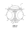
- a block 14 includes attached micro-electromechanical system devices such as gyroscopes or accelerometers (not shown), beneath protective covers 8 attached to faces 9 of the block 14. Vibration isolators 10 according to the prior art are attached to each corner 11 of the block 14.
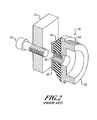
- a prior art isolator 10 includes an elastomeric damper 18, made of rubber, silicon, or other elastomeric materials known in the art.
- Example isolators 10 are made by many companies, including Barry Controls and the Lord Corporation.
- the damper 18 is molded to an outer connector 20 and an inner connector 22, both of which may be made of aluminum, stainless steel, or other materials known in the art.
- the damper 18 prevents contact between the outer connector 20 and the inner connector 22.
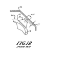
- the isolator 10 is attached to the block 14 at a corner 11 of the block 14 by screwing external threads 24 of the inner connector 22 into a threaded aperture (not shown) in each corner 11, and a screw 16 attaches the enclosure 12 to the isolator 10 via internal threads 26 in the outer connector 20.
- corner-mounted isolators 10 One problem with corner-mounted isolators 10 is that the tolerances of the enclosure 12, the block 14, and the isolators 10 are of limited precision such that when the block 14 with attached isolators 10 is inserted into the enclosure 12, there are gaps 17 between the isolators 10 and the enclosure 12.
- a block 14 with attached isolators 10 is mounted in an enclosure 12 via screws 16 through the enclosure 12 and isolators 10, the isolators 10 are compressed or stretched by some small amount. This distortion of the isolators 10 causes a shift or misalignment of the block 14 with the enclosure 12, which can be on the order of 0.02 inches on a one inch diameter isolator 10. This distortion alters the vibration isolation characteristics of the isolators 10.
- the present invention provides a vibration isolation system.
- An example embodiment of the invention includes a vibration isolator with an elastomeric damper and inner and outer connectors.
- the inner connector has external and internal threads, and the outer connector has internal threads.
- the device also includes a pair of screws, one for connecting the isolator to an enclosure, and one for connecting the isolator to a block.
- the vibration isolator is attached to a block by screwing external threads of an internal connector of the isolator into the block.
- the block with attached isolators is inserted into an enclosure, and each isolator is loosened as necessary to make a flush fit with the enclosure.
- a screw is then inserted into each isolator and fastens the isolator to the block at the flush position. Finally, a screw is inserted through the enclosure into each isolator to connect the isolators to the enclosure.
- a vibration isolator 30 reduces the amount of vibration transmitted from an enclosure 12 to a block 14.
- the vibration isolator 30 includes an outer connector 32 attachable to the enclosure 12, an inner connector 38 attachable to the block 14, and an elastomeric damper 36 coupled to the outer connector 32 and the inner connector 38.
- the damper 36 prevents contact between the outer connector 32 and the inner connector 38.
- the outer connector 32 includes a hollow cylinder 33 with internal threads 34 and a flat outer flange 35 for making flush contact with the enclosure 12.
- the elastomeric damper 36 is conical, tapering from the inner connector 38 to the outer connector 32, and includes a hollow cylinder 37 axially aligned with the threaded cylinder 33 of the outer connector 32.
- the inner connector 38 includes a hollow cylinder 39 with external threads 40, and a flat outer flange 43 attached to the damper 36.
- the isolator 30 is attached to a block 14 via external threads 40 and an internal screw 44 attached to the block 14 at threads 42.
- the isolator 30 is attached to an enclosure 12 via an external screw 46 and the internal threads 34.
- the damper 36 for example, may be an elastomeric material such as rubber, and the connectors 32,38 may be stainless steel. As long as the connectors 32,38 are very rigid, and the damper 36 is relatively soft, many materials may be used.
- the internal screw head 48 has a larger diameter than the internal screw shaft 50. Additionally, the internal screw head 48 has a smaller diameter than the outer connector internal threads 34 such that the threads 34 do not interfere with the movement of the internal screw 44.
- FIGURE 4 With reference to FIGURES 4 and 5A-5C , an embodiment of a method according to the present invention is illustrated.
- an isolator 30 is attached to each corner 11 of a block 14 by screwing the external threads 40 of the inner connector 3 8 of each isolator 30 into a first threaded receptacle 62 of a corner 11 of the block 14.
- the block 14 with attached isolators 30 is inserted into an enclosure 12, as illustrated in FIGURE 5A .
- each isolator 30 is unscrewed as necessary using a tool 64 (which may be a hex wrench, a torque wrench, or other suitable tool) to eliminate gaps 17 between each isolator 30 and the enclosure 12, as illustrated in FIGURE 5B .
- a tool 64 which may be a hex wrench, a torque wrench, or other suitable tool
- an internal screw 44 is inserted into each isolator 30 and a second threaded receptacle 66 of the corner 11 of the block 14 and tightened to fix the position of the isolator 30 relative to the block 14, also shown in FIGURE 5B .
- an external screw 46 is inserted through the enclosure 12 into each isolator 30 and tightened to attach the isolator 30 to the enclosure 12, as illustrated in FIGURE 5C .
Landscapes
- Engineering & Computer Science (AREA)
- General Engineering & Computer Science (AREA)
- Chemical & Material Sciences (AREA)
- Combustion & Propulsion (AREA)
- Physics & Mathematics (AREA)
- Acoustics & Sound (AREA)
- Aviation & Aerospace Engineering (AREA)
- Mechanical Engineering (AREA)
- Vibration Prevention Devices (AREA)
Applications Claiming Priority (1)
| Application Number | Priority Date | Filing Date | Title |
|---|---|---|---|
| US11/758,819 US8061695B2 (en) | 2007-06-06 | 2007-06-06 | Adjustable mounting vibration isolator |
Publications (1)
| Publication Number | Publication Date |
|---|---|
| EP2000697A2 true EP2000697A2 (de) | 2008-12-10 |
Family
ID=39720546
Family Applications (1)
| Application Number | Title | Priority Date | Filing Date |
|---|---|---|---|
| EP08157522A Withdrawn EP2000697A2 (de) | 2007-06-06 | 2008-06-03 | Einstellbarer Montageschwingungsdämpfer |
Country Status (2)
| Country | Link |
|---|---|
| US (1) | US8061695B2 (de) |
| EP (1) | EP2000697A2 (de) |
Cited By (2)
| Publication number | Priority date | Publication date | Assignee | Title |
|---|---|---|---|---|
| EP2946995A4 (de) * | 2013-11-22 | 2016-04-20 | Yamaha Motor Co Ltd | Sattelfahrzeug |
| WO2019115359A1 (fr) * | 2017-12-12 | 2019-06-20 | Safran Electronics & Defense | Unité inertielle améliorée à dispositif inertiel suspendu |
Families Citing this family (1)
| Publication number | Priority date | Publication date | Assignee | Title |
|---|---|---|---|---|
| KR20130039487A (ko) * | 2011-10-12 | 2013-04-22 | 한국후꼬꾸 주식회사 | 토셔널 바이브레이션 댐퍼 |
Family Cites Families (6)
| Publication number | Priority date | Publication date | Assignee | Title |
|---|---|---|---|---|
| WO1991002921A1 (en) | 1989-08-16 | 1991-03-07 | Platus David L | Vibration isolation system |
| US5318397A (en) * | 1992-05-07 | 1994-06-07 | Junkers John K | Mechanical tensioner |
| US5927680A (en) * | 1997-07-01 | 1999-07-27 | Mcdonnell Douglas Corporation | Rate gyro isolation assembly |
| US6196514B1 (en) * | 1998-09-18 | 2001-03-06 | Csa Engineering, Inc. | Large airborne stabilization/vibration isolation system |
| WO2002010597A1 (en) * | 2000-07-28 | 2002-02-07 | Ozawa, Junzo | Fastening implement |
| US6695295B2 (en) * | 2000-11-15 | 2004-02-24 | R.M. Wade & Co. | Vibration-isolating device |
-
2007
- 2007-06-06 US US11/758,819 patent/US8061695B2/en not_active Expired - Fee Related
-
2008
- 2008-06-03 EP EP08157522A patent/EP2000697A2/de not_active Withdrawn
Cited By (5)
| Publication number | Priority date | Publication date | Assignee | Title |
|---|---|---|---|---|
| EP2946995A4 (de) * | 2013-11-22 | 2016-04-20 | Yamaha Motor Co Ltd | Sattelfahrzeug |
| WO2019115359A1 (fr) * | 2017-12-12 | 2019-06-20 | Safran Electronics & Defense | Unité inertielle améliorée à dispositif inertiel suspendu |
| CN111542729A (zh) * | 2017-12-12 | 2020-08-14 | 赛峰电子与防务公司 | 带有悬置的惯性装置的改进的惯性单元 |
| US10948298B2 (en) | 2017-12-12 | 2021-03-16 | Safran Electronics & Defense | Inertial unit with suspended inertial device |
| CN111542729B (zh) * | 2017-12-12 | 2021-08-24 | 赛峰电子与防务公司 | 带有悬置的惯性装置的改进的惯性单元 |
Also Published As
| Publication number | Publication date |
|---|---|
| US8061695B2 (en) | 2011-11-22 |
| US20080302621A1 (en) | 2008-12-11 |
Similar Documents
| Publication | Publication Date | Title |
|---|---|---|
| EP1381827B1 (de) | Kompaktes vibrations-isolationssystem für eine inertialsensoranordnung | |
| US8061695B2 (en) | Adjustable mounting vibration isolator | |
| CA2514219A1 (en) | Elastomeric vibration and shock isolation for inertial sensor assemblies | |
| US20080143030A1 (en) | Holding device | |
| EP0986734A1 (de) | Vibrationsisolatorsystem für einen inertialsensoranordnung | |
| EP1487609A1 (de) | Abgestimmt gedämpfter absorberträger | |
| WO2005040634A3 (en) | Instrumented platform for vibration-sensitive equipment | |
| US11275097B2 (en) | Method for mounting inertial sensor unit and inertial sensor unit | |
| JP3949123B2 (ja) | 航空機用モジュール取付装置 | |
| WO2004005747A3 (en) | Method and system for decoupling structural modes to provide consistent control system performance | |
| EP1435472A1 (de) | Schwingungsdämpfungseinrichtung mit Massedämpfer | |
| US5131621A (en) | Universal hold-down assembly for pump assemblies and the like | |
| CN102422029A (zh) | 用于附接第一部分到第二部分而第二部分本身附接到第三部分的装置,尤其机动车辆的三个部分的组件 | |
| US5957427A (en) | Isolation mounting device | |
| US20040185702A1 (en) | Vibration isolated transducer connector | |
| JP2001271820A (ja) | 緩み止めナット | |
| ATE428057T1 (de) | Vorrichtung zur vibrationsentkoppelten befestigung einer einrichtung an einer wand | |
| JP2005147226A (ja) | 減衰機能付き締結部材およびその締結部材を用いた防振装置 | |
| CN111542729B (zh) | 带有悬置的惯性装置的改进的惯性单元 | |
| CN224135631U (zh) | 连接机构 | |
| KR102536905B1 (ko) | L형 렌치 토크 아답터 | |
| JPH0632788U (ja) | 防振装置 | |
| CN221113731U (zh) | 一种汽车智能驾驶用复合传感器 | |
| JPH0437280Y2 (de) | ||
| JP2003090387A (ja) | マウント装置 |
Legal Events
| Date | Code | Title | Description |
|---|---|---|---|
| PUAI | Public reference made under article 153(3) epc to a published international application that has entered the european phase |
Free format text: ORIGINAL CODE: 0009012 |
|
| 17P | Request for examination filed |
Effective date: 20080603 |
|
| AK | Designated contracting states |
Kind code of ref document: A2 Designated state(s): AT BE BG CH CY CZ DE DK EE ES FI FR GB GR HR HU IE IS IT LI LT LU LV MC MT NL NO PL PT RO SE SI SK TR |
|
| AX | Request for extension of the european patent |
Extension state: AL BA MK RS |
|
| STAA | Information on the status of an ep patent application or granted ep patent |
Free format text: STATUS: THE APPLICATION HAS BEEN WITHDRAWN |
|
| 18W | Application withdrawn |
Effective date: 20130516 |