EP2000697A2 - Adjustable mounting vibration isolator - Google Patents
Adjustable mounting vibration isolator Download PDFInfo
- Publication number
- EP2000697A2 EP2000697A2 EP08157522A EP08157522A EP2000697A2 EP 2000697 A2 EP2000697 A2 EP 2000697A2 EP 08157522 A EP08157522 A EP 08157522A EP 08157522 A EP08157522 A EP 08157522A EP 2000697 A2 EP2000697 A2 EP 2000697A2
- Authority
- EP
- European Patent Office
- Prior art keywords
- block
- isolator
- connector
- enclosure
- internal threads
- Prior art date
- Legal status (The legal status is an assumption and is not a legal conclusion. Google has not performed a legal analysis and makes no representation as to the accuracy of the status listed.)
- Withdrawn
Links
Images


Classifications
-
- F—MECHANICAL ENGINEERING; LIGHTING; HEATING; WEAPONS; BLASTING
- F16—ENGINEERING ELEMENTS AND UNITS; GENERAL MEASURES FOR PRODUCING AND MAINTAINING EFFECTIVE FUNCTIONING OF MACHINES OR INSTALLATIONS; THERMAL INSULATION IN GENERAL
- F16F—SPRINGS; SHOCK-ABSORBERS; MEANS FOR DAMPING VIBRATION
- F16F15/00—Suppression of vibrations in systems; Means or arrangements for avoiding or reducing out-of-balance forces, e.g. due to motion
- F16F15/02—Suppression of vibrations of non-rotating, e.g. reciprocating systems; Suppression of vibrations of rotating systems by use of members not moving with the rotating systems
- F16F15/04—Suppression of vibrations of non-rotating, e.g. reciprocating systems; Suppression of vibrations of rotating systems by use of members not moving with the rotating systems using elastic means
- F16F15/08—Suppression of vibrations of non-rotating, e.g. reciprocating systems; Suppression of vibrations of rotating systems by use of members not moving with the rotating systems using elastic means with rubber springs ; with springs made of rubber and metal
-
- F—MECHANICAL ENGINEERING; LIGHTING; HEATING; WEAPONS; BLASTING
- F16—ENGINEERING ELEMENTS AND UNITS; GENERAL MEASURES FOR PRODUCING AND MAINTAINING EFFECTIVE FUNCTIONING OF MACHINES OR INSTALLATIONS; THERMAL INSULATION IN GENERAL
- F16F—SPRINGS; SHOCK-ABSORBERS; MEANS FOR DAMPING VIBRATION
- F16F2226/00—Manufacturing; Treatments
- F16F2226/04—Assembly or fixing methods; methods to form or fashion parts
-
- Y—GENERAL TAGGING OF NEW TECHNOLOGICAL DEVELOPMENTS; GENERAL TAGGING OF CROSS-SECTIONAL TECHNOLOGIES SPANNING OVER SEVERAL SECTIONS OF THE IPC; TECHNICAL SUBJECTS COVERED BY FORMER USPC CROSS-REFERENCE ART COLLECTIONS [XRACs] AND DIGESTS
- Y10—TECHNICAL SUBJECTS COVERED BY FORMER USPC
- Y10T—TECHNICAL SUBJECTS COVERED BY FORMER US CLASSIFICATION
- Y10T29/00—Metal working
- Y10T29/53—Means to assemble or disassemble
Definitions
- Inertial sensing instruments such as gyroscopes and accelerometers are often mounted on a platform or block.
- the block is then mounted in an enclosure using elastomeric vibration isolators.
- elastomeric vibration isolators For a cube-shaped block, it is desirable to attach the isolators to the corners of the block because it creates favorable dynamic response characteristics and saves space.
- corner-mounted vibration isolators the corners of the block are shaved off to create a flat surface on which to mount the isolators.
- a block 14 includes attached micro-electromechanical system devices such as gyroscopes or accelerometers (not shown), beneath protective covers 8 attached to faces 9 of the block 14. Vibration isolators 10 according to the prior art are attached to each corner 11 of the block 14.
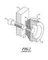
- a prior art isolator 10 includes an elastomeric damper 18, made of rubber, silicon, or other elastomeric materials known in the art.
- Example isolators 10 are made by many companies, including Barry Controls and the Lord Corporation.
- the damper 18 is molded to an outer connector 20 and an inner connector 22, both of which may be made of aluminum, stainless steel, or other materials known in the art.
- the damper 18 prevents contact between the outer connector 20 and the inner connector 22.
- the isolator 10 is attached to the block 14 at a corner 11 of the block 14 by screwing external threads 24 of the inner connector 22 into a threaded aperture (not shown) in each corner 11, and a screw 16 attaches the enclosure 12 to the isolator 10 via internal threads 26 in the outer connector 20.
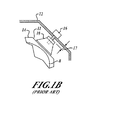
- corner-mounted isolators 10 One problem with corner-mounted isolators 10 is that the tolerances of the enclosure 12, the block 14, and the isolators 10 are of limited precision such that when the block 14 with attached isolators 10 is inserted into the enclosure 12, there are gaps 17 between the isolators 10 and the enclosure 12.
- a block 14 with attached isolators 10 is mounted in an enclosure 12 via screws 16 through the enclosure 12 and isolators 10, the isolators 10 are compressed or stretched by some small amount. This distortion of the isolators 10 causes a shift or misalignment of the block 14 with the enclosure 12, which can be on the order of 0.02 inches on a one inch diameter isolator 10. This distortion alters the vibration isolation characteristics of the isolators 10.
- the present invention provides a vibration isolation system.
- An example embodiment of the invention includes a vibration isolator with an elastomeric damper and inner and outer connectors.
- the inner connector has external and internal threads, and the outer connector has internal threads.
- the device also includes a pair of screws, one for connecting the isolator to an enclosure, and one for connecting the isolator to a block.
- the vibration isolator is attached to a block by screwing external threads of an internal connector of the isolator into the block.
- the block with attached isolators is inserted into an enclosure, and each isolator is loosened as necessary to make a flush fit with the enclosure.
- a screw is then inserted into each isolator and fastens the isolator to the block at the flush position. Finally, a screw is inserted through the enclosure into each isolator to connect the isolators to the enclosure.
- a vibration isolator 30 reduces the amount of vibration transmitted from an enclosure 12 to a block 14.
- the vibration isolator 30 includes an outer connector 32 attachable to the enclosure 12, an inner connector 38 attachable to the block 14, and an elastomeric damper 36 coupled to the outer connector 32 and the inner connector 38.
- the damper 36 prevents contact between the outer connector 32 and the inner connector 38.
- the outer connector 32 includes a hollow cylinder 33 with internal threads 34 and a flat outer flange 35 for making flush contact with the enclosure 12.
- the elastomeric damper 36 is conical, tapering from the inner connector 38 to the outer connector 32, and includes a hollow cylinder 37 axially aligned with the threaded cylinder 33 of the outer connector 32.
- the inner connector 38 includes a hollow cylinder 39 with external threads 40, and a flat outer flange 43 attached to the damper 36.
- the isolator 30 is attached to a block 14 via external threads 40 and an internal screw 44 attached to the block 14 at threads 42.
- the isolator 30 is attached to an enclosure 12 via an external screw 46 and the internal threads 34.
- the damper 36 for example, may be an elastomeric material such as rubber, and the connectors 32,38 may be stainless steel. As long as the connectors 32,38 are very rigid, and the damper 36 is relatively soft, many materials may be used.
- the internal screw head 48 has a larger diameter than the internal screw shaft 50. Additionally, the internal screw head 48 has a smaller diameter than the outer connector internal threads 34 such that the threads 34 do not interfere with the movement of the internal screw 44.
- FIGURE 4 With reference to FIGURES 4 and 5A-5C , an embodiment of a method according to the present invention is illustrated.
- an isolator 30 is attached to each corner 11 of a block 14 by screwing the external threads 40 of the inner connector 3 8 of each isolator 30 into a first threaded receptacle 62 of a corner 11 of the block 14.
- the block 14 with attached isolators 30 is inserted into an enclosure 12, as illustrated in FIGURE 5A .
- each isolator 30 is unscrewed as necessary using a tool 64 (which may be a hex wrench, a torque wrench, or other suitable tool) to eliminate gaps 17 between each isolator 30 and the enclosure 12, as illustrated in FIGURE 5B .
- a tool 64 which may be a hex wrench, a torque wrench, or other suitable tool
- an internal screw 44 is inserted into each isolator 30 and a second threaded receptacle 66 of the corner 11 of the block 14 and tightened to fix the position of the isolator 30 relative to the block 14, also shown in FIGURE 5B .
- an external screw 46 is inserted through the enclosure 12 into each isolator 30 and tightened to attach the isolator 30 to the enclosure 12, as illustrated in FIGURE 5C .
Landscapes
- Engineering & Computer Science (AREA)
- General Engineering & Computer Science (AREA)
- Chemical & Material Sciences (AREA)
- Combustion & Propulsion (AREA)
- Physics & Mathematics (AREA)
- Acoustics & Sound (AREA)
- Aviation & Aerospace Engineering (AREA)
- Mechanical Engineering (AREA)
- Vibration Prevention Devices (AREA)
Abstract
A device of the invention includes a vibration isolator with an elastomeric damper and inner and outer connectors. The inner connector has external and internal threads, and the outer connector has internal threads. A method of the invention includes attaching the vibration isolator to a block by screwing external threads of an internal connector of the isolator into the block. The block with attached isolators is inserted into an enclosure, and each isolator is loosened as necessary to make a flush fit with the enclosure. A screw is then inserted into each isolator and fastens the isolator to the block at the flush position. Finally, a screw is inserted through the enclosure into each isolator to connect the isolators to the enclosure.
Description
- Inertial sensing instruments such as gyroscopes and accelerometers are often mounted on a platform or block. The block is then mounted in an enclosure using elastomeric vibration isolators. For a cube-shaped block, it is desirable to attach the isolators to the corners of the block because it creates favorable dynamic response characteristics and saves space. In the case of corner-mounted vibration isolators, the corners of the block are shaved off to create a flat surface on which to mount the isolators.
- Referring to
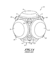
FIGURES 1A ,1B , and2 , ablock 14 includes attached micro-electromechanical system devices such as gyroscopes or accelerometers (not shown), beneathprotective covers 8 attached to faces 9 of theblock 14.Vibration isolators 10 according to the prior art are attached to eachcorner 11 of theblock 14. - A
prior art isolator 10 includes anelastomeric damper 18, made of rubber, silicon, or other elastomeric materials known in the art.Example isolators 10 are made by many companies, including Barry Controls and the Lord Corporation. Thedamper 18 is molded to anouter connector 20 and aninner connector 22, both of which may be made of aluminum, stainless steel, or other materials known in the art. Thedamper 18 prevents contact between theouter connector 20 and theinner connector 22. Theisolator 10 is attached to theblock 14 at acorner 11 of theblock 14 by screwingexternal threads 24 of theinner connector 22 into a threaded aperture (not shown) in eachcorner 11, and ascrew 16 attaches theenclosure 12 to theisolator 10 viainternal threads 26 in theouter connector 20. One problem with corner-mountedisolators 10 is that the tolerances of theenclosure 12, theblock 14, and theisolators 10 are of limited precision such that when theblock 14 with attachedisolators 10 is inserted into theenclosure 12, there aregaps 17 between theisolators 10 and theenclosure 12. When ablock 14 with attachedisolators 10 is mounted in anenclosure 12 viascrews 16 through theenclosure 12 andisolators 10, theisolators 10 are compressed or stretched by some small amount. This distortion of theisolators 10 causes a shift or misalignment of theblock 14 with theenclosure 12, which can be on the order of 0.02 inches on a oneinch diameter isolator 10. This distortion alters the vibration isolation characteristics of theisolators 10. - The present invention provides a vibration isolation system. An example embodiment of the invention includes a vibration isolator with an elastomeric damper and inner and outer connectors. The inner connector has external and internal threads, and the outer connector has internal threads. The device also includes a pair of screws, one for connecting the isolator to an enclosure, and one for connecting the isolator to a block.
- In an example embodiment, the vibration isolator is attached to a block by screwing external threads of an internal connector of the isolator into the block. The block with attached isolators is inserted into an enclosure, and each isolator is loosened as necessary to make a flush fit with the enclosure. A screw is then inserted into each isolator and fastens the isolator to the block at the flush position. Finally, a screw is inserted through the enclosure into each isolator to connect the isolators to the enclosure.
- Preferred and alternative embodiments of the present invention are described in detail below with reference to the following drawings:
-
FIGURE 1A is a perspective view of a block with attached isolators according to the prior art; -
FIGURE 1B is a cross-section of a face of the block ofFIGURE 1A with attached isolators in an enclosure; -
FIGURE 2 is an exploded cross-section of a prior art isolator, screw, and block; -
FIGURE 3A is an exploded partial cross-section of a device according to an embodiment of the present invention; -
FIGURE 3B is a perspective view of the device ofFIGURE 3A ; -
FIGURE 4 is a flow diagram of a method according an embodiment of the present invention; and -
FIGURES 5A, 5B, and 5C illustrate steps in the method ofFIGURE 4 . - With reference to
FIGURES 3A and 3B , avibration isolator 30 according to one embodiment of the present invention reduces the amount of vibration transmitted from anenclosure 12 to ablock 14. Thevibration isolator 30 includes anouter connector 32 attachable to theenclosure 12, aninner connector 38 attachable to theblock 14, and anelastomeric damper 36 coupled to theouter connector 32 and theinner connector 38. Thedamper 36 prevents contact between theouter connector 32 and theinner connector 38. - The
outer connector 32 includes ahollow cylinder 33 withinternal threads 34 and a flatouter flange 35 for making flush contact with theenclosure 12. Theelastomeric damper 36 is conical, tapering from theinner connector 38 to theouter connector 32, and includes ahollow cylinder 37 axially aligned with the threadedcylinder 33 of theouter connector 32. Theinner connector 38 includes ahollow cylinder 39 withexternal threads 40, and a flat outer flange 43 attached to thedamper 36. Theisolator 30 is attached to ablock 14 viaexternal threads 40 and aninternal screw 44 attached to theblock 14 atthreads 42. Theisolator 30 is attached to anenclosure 12 via anexternal screw 46 and theinternal threads 34. Thedamper 36, for example, may be an elastomeric material such as rubber, and theconnectors connectors damper 36 is relatively soft, many materials may be used. - In an embodiment, the
internal screw head 48 has a larger diameter than theinternal screw shaft 50. Additionally, theinternal screw head 48 has a smaller diameter than the outer connectorinternal threads 34 such that thethreads 34 do not interfere with the movement of theinternal screw 44. - With reference to
FIGURES 4 and5A-5C , an embodiment of a method according to the present invention is illustrated. InFIGURE 4 , at ablock 52, anisolator 30 is attached to eachcorner 11 of ablock 14 by screwing theexternal threads 40 of the inner connector 3 8 of eachisolator 30 into a first threadedreceptacle 62 of acorner 11 of theblock 14. At ablock 54, theblock 14 with attachedisolators 30 is inserted into anenclosure 12, as illustrated inFIGURE 5A . At ablock 56, eachisolator 30 is unscrewed as necessary using a tool 64 (which may be a hex wrench, a torque wrench, or other suitable tool) to eliminategaps 17 between eachisolator 30 and theenclosure 12, as illustrated inFIGURE 5B . At ablock 58, aninternal screw 44 is inserted into eachisolator 30 and a second threadedreceptacle 66 of thecorner 11 of theblock 14 and tightened to fix the position of theisolator 30 relative to theblock 14, also shown inFIGURE 5B . Finally, at ablock 60, anexternal screw 46 is inserted through theenclosure 12 into eachisolator 30 and tightened to attach theisolator 30 to theenclosure 12, as illustrated inFIGURE 5C . - While the preferred embodiment of the invention has been illustrated and described, as noted above, many changes can be made without departing from the spirit and scope of the invention. For example, the example embodiments are shown using hex tools and hex nuts, but other fasteners could be used. Accordingly, the scope of the invention is not limited by the disclosure of the preferred embodiment. Instead, the invention should be determined entirely by reference to the claims that follow.
The embodiments of the invention in which an exclusive property or privilege is claimed are defined as follows:
Claims (8)
- A device (30) comprising:a damper (36);an outer connector (32) with internal threads (34), the outer connector attached to the damper; andan inner connector (38) including a hollow cylinder (39) with external threads (40), the inner connector attached to the damper.
- The device of Claim 1, wherein the internal threads of the outer connector are coaxial with the hollow cylinder of the inner connector.
- The device of Claim 2, wherein the internal threads of the outer connector are sized and shaped such that an internal screw (44) sized and shaped to engage internal threads of a block can be inserted through the internal threads of the outer connector without engaging the internal threads of the outer connector.
- The device of Claim 1, further including a block (14), the block having shaved-off corners creating flat surfaces (11) for mounting to inner connectors (38), the flat surfaces further comprising:a first threaded receptacle (62) sized and shaped to receive the external threads (40) of the inner connector; anda second threaded receptacle (66) sized and shaped to receive an internal screw (44).
- The device of Claim 4, wherein the first and second threaded receptacles are coaxial, and the first threaded receptacle has a larger diameter than the second threaded receptacle.
- The device of Claim 1, wherein the damper is an elastomeric damper.
- The device of Claim 1, wherein the inner connector and the outer connector are made of stainless steel.
- The device of Claim 1, wherein the outer connector includes a hollow cylinder (33) having the internal threads.
Applications Claiming Priority (1)
| Application Number | Priority Date | Filing Date | Title |
|---|---|---|---|
| US11/758,819 US8061695B2 (en) | 2007-06-06 | 2007-06-06 | Adjustable mounting vibration isolator |
Publications (1)
| Publication Number | Publication Date |
|---|---|
| EP2000697A2 true EP2000697A2 (en) | 2008-12-10 |
Family
ID=39720546
Family Applications (1)
| Application Number | Title | Priority Date | Filing Date |
|---|---|---|---|
| EP08157522A Withdrawn EP2000697A2 (en) | 2007-06-06 | 2008-06-03 | Adjustable mounting vibration isolator |
Country Status (2)
| Country | Link |
|---|---|
| US (1) | US8061695B2 (en) |
| EP (1) | EP2000697A2 (en) |
Cited By (2)
| Publication number | Priority date | Publication date | Assignee | Title |
|---|---|---|---|---|
| EP2946995A4 (en) * | 2013-11-22 | 2016-04-20 | Yamaha Motor Co Ltd | SEAT TYPE VEHICLE |
| WO2019115359A1 (en) * | 2017-12-12 | 2019-06-20 | Safran Electronics & Defense | Improved inertial unit with suspended inertial device |
Families Citing this family (1)
| Publication number | Priority date | Publication date | Assignee | Title |
|---|---|---|---|---|
| KR20130039487A (en) * | 2011-10-12 | 2013-04-22 | 한국후꼬꾸 주식회사 | Torsional vibration damper |
Family Cites Families (6)
| Publication number | Priority date | Publication date | Assignee | Title |
|---|---|---|---|---|
| DE69032856T2 (en) | 1989-08-16 | 1999-07-22 | David L. Santa Monica Cailf. Platus | VIBRATION DAMPING SYSTEM |
| US5318397A (en) * | 1992-05-07 | 1994-06-07 | Junkers John K | Mechanical tensioner |
| US5927680A (en) * | 1997-07-01 | 1999-07-27 | Mcdonnell Douglas Corporation | Rate gyro isolation assembly |
| US6196514B1 (en) * | 1998-09-18 | 2001-03-06 | Csa Engineering, Inc. | Large airborne stabilization/vibration isolation system |
| WO2002010597A1 (en) * | 2000-07-28 | 2002-02-07 | Ozawa, Junzo | Fastening implement |
| US6695295B2 (en) * | 2000-11-15 | 2004-02-24 | R.M. Wade & Co. | Vibration-isolating device |
-
2007
- 2007-06-06 US US11/758,819 patent/US8061695B2/en not_active Expired - Fee Related
-
2008
- 2008-06-03 EP EP08157522A patent/EP2000697A2/en not_active Withdrawn
Cited By (5)
| Publication number | Priority date | Publication date | Assignee | Title |
|---|---|---|---|---|
| EP2946995A4 (en) * | 2013-11-22 | 2016-04-20 | Yamaha Motor Co Ltd | SEAT TYPE VEHICLE |
| WO2019115359A1 (en) * | 2017-12-12 | 2019-06-20 | Safran Electronics & Defense | Improved inertial unit with suspended inertial device |
| CN111542729A (en) * | 2017-12-12 | 2020-08-14 | 赛峰电子与防务公司 | Improved inertial unit with suspended inertial device |
| US10948298B2 (en) | 2017-12-12 | 2021-03-16 | Safran Electronics & Defense | Inertial unit with suspended inertial device |
| CN111542729B (en) * | 2017-12-12 | 2021-08-24 | 赛峰电子与防务公司 | Improved inertial unit with suspended inertial device |
Also Published As
| Publication number | Publication date |
|---|---|
| US20080302621A1 (en) | 2008-12-11 |
| US8061695B2 (en) | 2011-11-22 |
Similar Documents
| Publication | Publication Date | Title |
|---|---|---|
| EP1381827B1 (en) | Compact vibration isolation system for an inertial sensor assembly | |
| US20040150144A1 (en) | Elastomeric vibration and shock isolation for inertial sensor assemblies | |
| US8061695B2 (en) | Adjustable mounting vibration isolator | |
| EP1487609A1 (en) | Tuned damped absorber support | |
| US7624618B2 (en) | Device with a screw plug and a range of devices | |
| WO2005040634A3 (en) | Instrumented platform for vibration-sensitive equipment | |
| US11275097B2 (en) | Method for mounting inertial sensor unit and inertial sensor unit | |
| JP3949123B2 (en) | Aircraft module mounting device | |
| WO2004005747A3 (en) | Method and system for decoupling structural modes to provide consistent control system performance | |
| EP1435472A1 (en) | Antivibration apparatus including a mass damper | |
| US5131621A (en) | Universal hold-down assembly for pump assemblies and the like | |
| CN102422029A (en) | Device for attaching a first part to a second part which is itself attached to a third part, in particular an assembly of three parts of a motor vehicle | |
| US5957427A (en) | Isolation mounting device | |
| US7186131B2 (en) | Vibration isolated transducer connector | |
| ATE428057T1 (en) | DEVICE FOR FASTENING A DEVICE TO A WALL WITHOUT VIBRATION | |
| JP2001271820A (en) | Locking nut | |
| JP2005147226A (en) | Fastening member with damping function and vibration isolator using the fastening member | |
| CN111542729B (en) | Improved inertial unit with suspended inertial device | |
| CN224135631U (en) | Connection mechanism | |
| JPS6349272Y2 (en) | ||
| KR102536905B1 (en) | L-type wrench torque adapter | |
| JPH0632788U (en) | Anti-vibration device | |
| JPH0437280Y2 (en) | ||
| JP2002184535A (en) | Mounting structure of high frequency connector | |
| JPH0624245U (en) | Anti-vibration support structure and anti-vibration member for small precision equipment |
Legal Events
| Date | Code | Title | Description |
|---|---|---|---|
| PUAI | Public reference made under article 153(3) epc to a published international application that has entered the european phase |
Free format text: ORIGINAL CODE: 0009012 |
|
| 17P | Request for examination filed |
Effective date: 20080603 |
|
| AK | Designated contracting states |
Kind code of ref document: A2 Designated state(s): AT BE BG CH CY CZ DE DK EE ES FI FR GB GR HR HU IE IS IT LI LT LU LV MC MT NL NO PL PT RO SE SI SK TR |
|
| AX | Request for extension of the european patent |
Extension state: AL BA MK RS |
|
| STAA | Information on the status of an ep patent application or granted ep patent |
Free format text: STATUS: THE APPLICATION HAS BEEN WITHDRAWN |
|
| 18W | Application withdrawn |
Effective date: 20130516 |