EP2000696A2 - Soupape d'amortissement pour un amortisseur d'oscillations - Google Patents
Soupape d'amortissement pour un amortisseur d'oscillations Download PDFInfo
- Publication number
- EP2000696A2 EP2000696A2 EP08154180A EP08154180A EP2000696A2 EP 2000696 A2 EP2000696 A2 EP 2000696A2 EP 08154180 A EP08154180 A EP 08154180A EP 08154180 A EP08154180 A EP 08154180A EP 2000696 A2 EP2000696 A2 EP 2000696A2
- Authority
- EP
- European Patent Office
- Prior art keywords
- clamping
- disc
- valve
- damper
- fixing
- Prior art date
- Legal status (The legal status is an assumption and is not a legal conclusion. Google has not performed a legal analysis and makes no representation as to the accuracy of the status listed.)
- Withdrawn
Links
- 238000013016 damping Methods 0.000 title claims abstract description 20
- 230000005540 biological transmission Effects 0.000 claims abstract description 4
- 238000005452 bending Methods 0.000 description 7
- 238000013461 design Methods 0.000 description 7
- 238000012546 transfer Methods 0.000 description 6
- 230000006835 compression Effects 0.000 description 1
- 238000007906 compression Methods 0.000 description 1
- 230000001419 dependent effect Effects 0.000 description 1
- 230000000694 effects Effects 0.000 description 1
- 238000011156 evaluation Methods 0.000 description 1
- 238000005259 measurement Methods 0.000 description 1
- 238000012360 testing method Methods 0.000 description 1
Images


Classifications
-
- F—MECHANICAL ENGINEERING; LIGHTING; HEATING; WEAPONS; BLASTING
- F16—ENGINEERING ELEMENTS AND UNITS; GENERAL MEASURES FOR PRODUCING AND MAINTAINING EFFECTIVE FUNCTIONING OF MACHINES OR INSTALLATIONS; THERMAL INSULATION IN GENERAL
- F16F—SPRINGS; SHOCK-ABSORBERS; MEANS FOR DAMPING VIBRATION
- F16F9/00—Springs, vibration-dampers, shock-absorbers, or similarly-constructed movement-dampers using a fluid or the equivalent as damping medium
- F16F9/32—Details
- F16F9/34—Special valve constructions; Shape or construction of throttling passages
- F16F9/348—Throttling passages in the form of annular discs or other plate-like elements which may or may not have a spring action, operating in opposite directions or singly, e.g. annular discs positioned on top of the valve or piston body
- F16F9/3485—Throttling passages in the form of annular discs or other plate-like elements which may or may not have a spring action, operating in opposite directions or singly, e.g. annular discs positioned on top of the valve or piston body characterised by features of supporting elements intended to guide or limit the movement of the annular discs
Definitions
- the invention relates to a damping valve for a vibration damper according to the preamble of patent claim 1.
- the DE 10 2004 060 485 A1 describes a damping valve for a vibration damper, which is arranged on a piston rod, wherein the damping valve comprises a valve body on which on both sides at least one elastic valve disc is arranged, the throttle channels in the valve body at least partially covered.
- the damping valve together with valve disks is braced via support and support disks, at the lower end in addition by a shim between a lying above the damping valve fixing surface and a nut on the piston rod end.
- a contact area between the support and the shim is designed as a surface raised by the base body.
- the base body can be both the support disk, as well as the shim. This repeat accuracy is important in that as in DE 101 59 936 C1 described The slightest changes in the lever lengths of the components clamped on one side have a considerable influence on the damping characteristics.
- the object of the present invention is to remedy the problems of the voltage loss of the valve disks known from the prior art.
- the object is achieved in that the average point of force application of the clamping surface between the center of force application point of the fixing surface and the central point of force application of the support surface is arranged.
- the power flow path of the tension chain can thereby be guided such that a bending moment is transmitted to the at least one elastic valve disc and thus the problem of the voltage loss is eliminated. This result was confirmed by the evaluation of numerous test series.
- the simplest embodiment of a clamping surface is the use of a flat clamping disk.
- the possibility is given to interpret the radial course of the power flow path of the stress chain individually according to the space. This can be done by choosing the radial extent of the centering disc, as e.g. depending on the number or thickness of the valve discs an adjusted bending moment must be transmitted. It should be noted that the axial extent of the centering disc may be at most equal to the clamping disc, so that the transmission of a bending moment can be ensured on the at least one valve disc.
- the use of a centering disc also advantageously avoids the occurrence of rattling noise, since there is thus no radial play for the tensioning disc.
- valve body For the design of the valve body there are many variants, especially in connection with the radial position of the fixing and the clamping surface.
- a transfer disc which acts directly on the clamping disk in the tension chain, thus the invention can be used independently of the valve body variant.
- a further advantageous embodiment represents a stepped contour of the clamping disk directed towards the valve disk.
- the raised surface forms the clamping surface.
- the axially small stage of the clamping disc is a safety precaution, since the at least one elastic valve disc on the spaced surface to the fixing surface of the clamping plate comes to rest before the valve disc is biased excessively.
- the bending moment can be varied to the at least one valve disk.
- the clamping surface can also be formed on a raised surface of a fastening means.
- a fastening means e.g. often used piston nuts as fasteners. If the clamping surface is thus already integrated into the fastening means, it is possible to dispense with further individual parts in this section of the tension chain, which minimizes the assembly effort.
- the use of a separate fixing disc is particularly advantageous. Because by the fact that between the fixing surface and the Supporting surface often a ring trench is provided to increase the pressurized surface, regardless of the valve body by the variation of the width, and the height of the fixing washer, the influence of this area can be influenced.
- the fixing surface can also be formed by a raised surface of the valve body. This reduces the assembly effort due to the smaller number of parts.
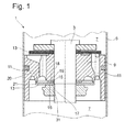
- the Fig. 1 shows a damping valve 1 in the embodiment of a piston valve for a vibration damper. This is mounted on an axially movable piston rod 3 and divides a filled with damping medium cylinder 5 in two working spaces 7.
- the piston valve consists essentially of a valve body 9, which has directional passage openings 11 for the tension and compression direction. In order to achieve a damping effect, the passage openings 11 are at least partially covered with at least one elastic valve disc 13 depending on the direction, this being braced between a valve body-side fixing surface 15 and a clamping surface 17.
- Fig. 1 shown on a piston top a known from the prior art valve disc assembly.
- the fixing surface 15 is formed in the pulling direction of the piston rod 3 by a separate fixing plate 19, which forms a clamping plane together with a support surface 21.
- the support surface 21 is designed as a raised flat surface of the valve body 9, wherein the axial distance to the clamping surface 17 is less than that of the fixing surface 15 to the clamping surface 17.
- the at least one elastic valve disc 13 and a Befestigunsstoff 31 are arranged, which shown here in a similar form of a piston nut, via a raised in the direction of the elastic valve disc 13 clamping surface 17 has.
- the outer diameter of the clamping surface 17 is made larger than that of the fixing surface 15.
- Fig. 2 becomes an alternative to in Fig. 1 shown solution shown.
- the piston underside is considered again.
- the design of the support plane for the at least one elastic valve disc 13 corresponds to the in Fig.1 ,
- the clamping surface 17 is, however, carried out on a separate clamping disk 25, which is centered by means of a centering disc 27 to the valve body 9, wherein the axial extent of the centering disc 27 corresponds to the maximum of the clamping plate 25, so that the power flow path guaranteed by the clamping plate 25 can be passed.
- the radial extent of the centering disc 27 is dependent on the desired damping force line, because the radially closer the average force application point 16 of the tensioning disc 25 to the center of force application point 20 of the support surface 21, the greater the effective bending moment on the elastic valve disc 13.
- the centering disc used 27 identical to the fixing disc 19. This can occur, for example, no confusion during assembly.
- a support plate 29 is arranged in the direction of a piston nut as a fastening means 31 following the clamping and centering disk 25, 19. With a tightening torque on the fastener 31, the tension chain is finally closed.
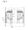
- FIG. 3 Another embodiment is in Fig. 3 shown.
- Fig. 2 used solution with clamping disk 25 and centering plate 27 can also be realized in one piece with the aid of a clamping plate 25 with stepped contour.
- the stepped contour is executed to the valve disc 13 and has on its raised surface, the clamping surface 17.
- the fixing surface 15 is here as well as the support surface 21 formed by a raised surface of the valve body 9 and thus determines the clamping plane, as in Fig. 1 described has a small height offset.
- a ring is arranged via a press fit, which introduces the force into the tension chain.
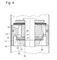
- a transmission disk 33 (FIG. Fig. 4 ), which acts directly on the tension pulley 25 in the tension chain, the power flow can be directed from a piston rod-side path to a cylinder-side path.
- the diameters of the clamping and the fixing surface 17, 15 are chosen so that a bending moment can be transmitted to the elastic valve disc 13.
- the clamping level becomes functionally identical to Fig. 1 formed, wherein the support surface 21 piston rod side and the fixing surface 15 is arranged on the cylinder side.
- the clamping plate 25 is also as in Fig. 1 centered by a centering plate 27 to the piston rod 3, wherein these and the transfer disc 33 have passage openings 35 for the damping medium to connect both working spaces 7 miteinender.
- the transfer disc 33 fulfills the function of a support disk (29 off Fig. 2 ), as it defines the maximum Abhubweg the elastically deformable portion of the valve disc 13.
- the Fig. 5 shows the one-piece variant of in Fig. 4 described embodiment.
- a pot-shaped clamping disk 25 is used. This has as the transfer disk 33 through openings 35.
- the force flow path can again be influenced in its radial path depending on the design of the pot bottom width 37.
- For the at least one elastic valve disc is also fulfilled by the cup-shaped clamping disk 25.
- a piston nut as a fastening means 31 in turn forms the conclusion of the tension chain.
Landscapes
- Engineering & Computer Science (AREA)
- General Engineering & Computer Science (AREA)
- Mechanical Engineering (AREA)
- Fluid-Damping Devices (AREA)
- Check Valves (AREA)
Applications Claiming Priority (1)
| Application Number | Priority Date | Filing Date | Title |
|---|---|---|---|
| DE102007026571A DE102007026571A1 (de) | 2007-06-08 | 2007-06-08 | Dämpfventil für einen Schwingungsdämpfer |
Publications (2)
| Publication Number | Publication Date |
|---|---|
| EP2000696A2 true EP2000696A2 (fr) | 2008-12-10 |
| EP2000696A3 EP2000696A3 (fr) | 2010-04-07 |
Family
ID=39734102
Family Applications (1)
| Application Number | Title | Priority Date | Filing Date |
|---|---|---|---|
| EP08154180A Withdrawn EP2000696A3 (fr) | 2007-06-08 | 2008-04-08 | Soupape d'amortissement pour un amortisseur d'oscillations |
Country Status (2)
| Country | Link |
|---|---|
| EP (1) | EP2000696A3 (fr) |
| DE (1) | DE102007026571A1 (fr) |
Families Citing this family (1)
| Publication number | Priority date | Publication date | Assignee | Title |
|---|---|---|---|---|
| DE102013008890A1 (de) * | 2013-05-27 | 2014-08-28 | Thyssenkrupp Bilstein Gmbh | Schwingungsdämpfer für ein Fahrzeug |
Citations (2)
| Publication number | Priority date | Publication date | Assignee | Title |
|---|---|---|---|---|
| DE10159936C1 (de) | 2001-12-06 | 2003-04-10 | Zf Sachs Ag | Dämpfventil, insbesondere für einen Schwingungsdämpfer |
| DE102004060485A1 (de) | 2003-12-20 | 2005-07-21 | Zf Friedrichshafen Ag | Dämpfventil |
Family Cites Families (7)
| Publication number | Priority date | Publication date | Assignee | Title |
|---|---|---|---|---|
| JPS58122043U (ja) * | 1982-02-12 | 1983-08-19 | トキコ株式会社 | 油圧緩衝器 |
| US4615420A (en) * | 1984-01-23 | 1986-10-07 | Ford Motor Company | Piston assembly for shock absorber |
| DE19932717C2 (de) * | 1999-07-16 | 2001-11-15 | Pnp Luftfedersysteme Gmbh | Feder-Dämpfer-Einheit für ein Kraftfahrzeug |
| US20020063023A1 (en) * | 2000-11-30 | 2002-05-30 | Delphi Technologies Inc. | Digressive piston compression valve |
| DE10163217B4 (de) * | 2001-12-21 | 2014-10-09 | Volkswagen Ag | Dämpferventil |
| JP2004211879A (ja) * | 2003-01-08 | 2004-07-29 | Showa Corp | 油圧緩衝器のボトムバルブ装置 |
| JP4955241B2 (ja) * | 2005-09-07 | 2012-06-20 | カヤバ工業株式会社 | 油圧緩衝器の減衰力発生バルブ構造 |
-
2007
- 2007-06-08 DE DE102007026571A patent/DE102007026571A1/de not_active Withdrawn
-
2008
- 2008-04-08 EP EP08154180A patent/EP2000696A3/fr not_active Withdrawn
Patent Citations (2)
| Publication number | Priority date | Publication date | Assignee | Title |
|---|---|---|---|---|
| DE10159936C1 (de) | 2001-12-06 | 2003-04-10 | Zf Sachs Ag | Dämpfventil, insbesondere für einen Schwingungsdämpfer |
| DE102004060485A1 (de) | 2003-12-20 | 2005-07-21 | Zf Friedrichshafen Ag | Dämpfventil |
Also Published As
| Publication number | Publication date |
|---|---|
| EP2000696A3 (fr) | 2010-04-07 |
| DE102007026571A1 (de) | 2008-12-11 |
Similar Documents
| Publication | Publication Date | Title |
|---|---|---|
| EP3084259B1 (fr) | Amortisseur réglable de vibrations pour véhicules automobiles | |
| DE3805763C2 (fr) | ||
| DE2430410A1 (de) | Ventil, insbesondere kugelventil | |
| DE102018102758B4 (de) | Feder für ein Rückschlagventil, Rückschlagventil mit einer derartigen Feder, regelbarer Schwingungsdämpfer mit einem solchen Rückschlagventil sowie Kraftfahrzeug mit einem derartigen regelbaren Schwingungsdämpfer | |
| EP2045484A2 (fr) | Soupape d'amortissement | |
| DE2206771A1 (de) | Hochdruckdichtung mit dem o-ring angepasster abstuetzflaeche und kantenbelastetem dichtring | |
| DE3508039C2 (de) | Innen umgriffene Scheibenbremse, insbesondere für Kraftfahrzeuge | |
| EP3153725B1 (fr) | Procede et dispositif de fixation d'un composant en plastique sur un composant porteur | |
| DE102009047261B3 (de) | Dämpfventileinrichtung mit einer mehrstufigen Dämpfkraftkennlinie | |
| EP1128085B1 (fr) | Support de base de ressort | |
| EP2032871B1 (fr) | Élément d'amortissement | |
| DE102013220627B3 (de) | Verfahren zum Befestigen eines Zuganschlags an einer Kolbenstange eines Schwingungsdämpfers | |
| DE4106442C2 (de) | Schwingungsdämpfungsvorrichtung mit belastungsabhängigem Dämpfungsverhalten | |
| DE2826923A1 (de) | Elastisches motorlager, insbesondere fuer kraftfahrzeuge | |
| DE19855974C1 (de) | Befestigung eines Dämpfkolbens auf einer Kolbenstange | |
| WO2002053933A1 (fr) | Dispositif de fixation de piston | |
| EP2000696A2 (fr) | Soupape d'amortissement pour un amortisseur d'oscillations | |
| EP1180079B1 (fr) | Mecanisme de transmission de la force de freinage destine a un servo-frein | |
| DE20005583U1 (de) | Verbindungselement für eine elastische Verbindung zweier Bauteile | |
| DE19505115A1 (de) | Dichtpaket für einen Geberzylinder | |
| DE4330367A1 (de) | Vorrichtung zum motorischen Längsverstellen eines Sitzes in einem Kraftfahrzeug | |
| DE102004024084B4 (de) | Vorrichtung zur schwingungsdämpfenden Lagerung | |
| DE102016217114A1 (de) | Frequenzabhängige Dämpfventilanordnung | |
| DE10317190A1 (de) | Schwingungsdämpfer mit hydraulischem Zuganschlag | |
| DE1200624B (de) | Rueckschlagventil, insbesondere fuer hydraulische Stossdaempfer |
Legal Events
| Date | Code | Title | Description |
|---|---|---|---|
| PUAI | Public reference made under article 153(3) epc to a published international application that has entered the european phase |
Free format text: ORIGINAL CODE: 0009012 |
|
| AK | Designated contracting states |
Kind code of ref document: A2 Designated state(s): AT BE BG CH CY CZ DE DK EE ES FI FR GB GR HR HU IE IS IT LI LT LU LV MC MT NL NO PL PT RO SE SI SK TR |
|
| AX | Request for extension of the european patent |
Extension state: AL BA MK RS |
|
| PUAL | Search report despatched |
Free format text: ORIGINAL CODE: 0009013 |
|
| AK | Designated contracting states |
Kind code of ref document: A3 Designated state(s): AT BE BG CH CY CZ DE DK EE ES FI FR GB GR HR HU IE IS IT LI LT LU LV MC MT NL NO PL PT RO SE SI SK TR |
|
| AX | Request for extension of the european patent |
Extension state: AL BA MK RS |
|
| 17P | Request for examination filed |
Effective date: 20101005 |
|
| 17Q | First examination report despatched |
Effective date: 20101029 |
|
| AKX | Designation fees paid |
Designated state(s): AT BE BG CH CY CZ DE DK EE ES FI FR GB GR HR HU IE IS IT LI LT LU LV MC MT NL NO PL PT RO SE SI SK TR |
|
| STAA | Information on the status of an ep patent application or granted ep patent |
Free format text: STATUS: THE APPLICATION IS DEEMED TO BE WITHDRAWN |
|
| 18D | Application deemed to be withdrawn |
Effective date: 20151103 |