EP2000587B1 - Dewatering system - Google Patents
Dewatering system Download PDFInfo
- Publication number
- EP2000587B1 EP2000587B1 EP08163021.2A EP08163021A EP2000587B1 EP 2000587 B1 EP2000587 B1 EP 2000587B1 EP 08163021 A EP08163021 A EP 08163021A EP 2000587 B1 EP2000587 B1 EP 2000587B1
- Authority
- EP
- European Patent Office
- Prior art keywords
- approximately
- fabric
- web
- permeable
- belt
- Prior art date
- Legal status (The legal status is an assumption and is not a legal conclusion. Google has not performed a legal analysis and makes no representation as to the accuracy of the status listed.)
- Expired - Lifetime
Links
- 239000004744 fabric Substances 0.000 claims description 396
- 239000000835 fiber Substances 0.000 claims description 64
- 238000003825 pressing Methods 0.000 claims description 56
- 239000007787 solid Substances 0.000 claims description 44
- 238000001035 drying Methods 0.000 claims description 39
- 239000012528 membrane Substances 0.000 claims description 23
- 239000011148 porous material Substances 0.000 claims description 22
- 230000035699 permeability Effects 0.000 claims description 16
- 239000000463 material Substances 0.000 claims description 15
- 230000007246 mechanism Effects 0.000 claims description 11
- 239000004952 Polyamide Substances 0.000 claims description 6
- 239000000853 adhesive Substances 0.000 claims description 6
- 230000001070 adhesive effect Effects 0.000 claims description 6
- 239000000203 mixture Substances 0.000 claims description 6
- 229920002647 polyamide Polymers 0.000 claims description 6
- 229920002292 Nylon 6 Polymers 0.000 claims description 4
- 238000003475 lamination Methods 0.000 claims description 4
- 239000013589 supplement Substances 0.000 claims description 4
- 210000002268 wool Anatomy 0.000 claims description 4
- 238000007639 printing Methods 0.000 claims description 3
- 239000010410 layer Substances 0.000 description 65
- 238000000034 method Methods 0.000 description 44
- XLYOFNOQVPJJNP-UHFFFAOYSA-N water Substances O XLYOFNOQVPJJNP-UHFFFAOYSA-N 0.000 description 34
- 230000008569 process Effects 0.000 description 30
- 230000000670 limiting effect Effects 0.000 description 17
- 210000001519 tissue Anatomy 0.000 description 14
- 230000002209 hydrophobic effect Effects 0.000 description 13
- 238000007670 refining Methods 0.000 description 13
- 239000002184 metal Substances 0.000 description 12
- 230000008901 benefit Effects 0.000 description 11
- 238000012546 transfer Methods 0.000 description 10
- 238000010586 diagram Methods 0.000 description 9
- 238000004519 manufacturing process Methods 0.000 description 9
- 229920002635 polyurethane Polymers 0.000 description 9
- 239000004814 polyurethane Substances 0.000 description 9
- 238000002844 melting Methods 0.000 description 7
- 238000010521 absorption reaction Methods 0.000 description 6
- 239000013536 elastomeric material Substances 0.000 description 6
- 230000008018 melting Effects 0.000 description 6
- 239000002344 surface layer Substances 0.000 description 6
- 238000007605 air drying Methods 0.000 description 5
- 230000000694 effects Effects 0.000 description 5
- 239000002657 fibrous material Substances 0.000 description 5
- 230000001965 increasing effect Effects 0.000 description 5
- 239000002245 particle Substances 0.000 description 5
- 239000002759 woven fabric Substances 0.000 description 5
- 239000002131 composite material Substances 0.000 description 4
- 239000006185 dispersion Substances 0.000 description 4
- 239000011159 matrix material Substances 0.000 description 4
- 230000036961 partial effect Effects 0.000 description 4
- 238000012545 processing Methods 0.000 description 4
- 238000001228 spectrum Methods 0.000 description 4
- 241000168096 Glareolidae Species 0.000 description 3
- 210000001601 blood-air barrier Anatomy 0.000 description 3
- 230000008859 change Effects 0.000 description 3
- 238000009826 distribution Methods 0.000 description 3
- 239000012530 fluid Substances 0.000 description 3
- 229920000642 polymer Polymers 0.000 description 3
- 230000002265 prevention Effects 0.000 description 3
- 230000002829 reductive effect Effects 0.000 description 3
- 239000011347 resin Substances 0.000 description 3
- 229920005989 resin Polymers 0.000 description 3
- 238000011282 treatment Methods 0.000 description 3
- 238000009736 wetting Methods 0.000 description 3
- 239000002250 absorbent Substances 0.000 description 2
- 230000009471 action Effects 0.000 description 2
- 238000005056 compaction Methods 0.000 description 2
- 238000010276 construction Methods 0.000 description 2
- 238000001816 cooling Methods 0.000 description 2
- 230000008878 coupling Effects 0.000 description 2
- 238000010168 coupling process Methods 0.000 description 2
- 238000005859 coupling reaction Methods 0.000 description 2
- 230000001419 dependent effect Effects 0.000 description 2
- 238000013461 design Methods 0.000 description 2
- 235000004879 dioscorea Nutrition 0.000 description 2
- -1 e.g. Polymers 0.000 description 2
- 239000006260 foam Substances 0.000 description 2
- 238000010438 heat treatment Methods 0.000 description 2
- 238000000465 moulding Methods 0.000 description 2
- 229910001220 stainless steel Inorganic materials 0.000 description 2
- 239000010935 stainless steel Substances 0.000 description 2
- 239000004753 textile Substances 0.000 description 2
- 239000004677 Nylon Substances 0.000 description 1
- 238000013459 approach Methods 0.000 description 1
- CUZMQPZYCDIHQL-VCTVXEGHSA-L calcium;(2s)-1-[(2s)-3-[(2r)-2-(cyclohexanecarbonylamino)propanoyl]sulfanyl-2-methylpropanoyl]pyrrolidine-2-carboxylate Chemical compound [Ca+2].N([C@H](C)C(=O)SC[C@@H](C)C(=O)N1[C@@H](CCC1)C([O-])=O)C(=O)C1CCCCC1.N([C@H](C)C(=O)SC[C@@H](C)C(=O)N1[C@@H](CCC1)C([O-])=O)C(=O)C1CCCCC1 CUZMQPZYCDIHQL-VCTVXEGHSA-L 0.000 description 1
- 239000011248 coating agent Substances 0.000 description 1
- 238000000576 coating method Methods 0.000 description 1
- 230000002860 competitive effect Effects 0.000 description 1
- 230000006835 compression Effects 0.000 description 1
- 238000007906 compression Methods 0.000 description 1
- 239000004020 conductor Substances 0.000 description 1
- 238000005553 drilling Methods 0.000 description 1
- 238000005516 engineering process Methods 0.000 description 1
- 230000002708 enhancing effect Effects 0.000 description 1
- 238000001125 extrusion Methods 0.000 description 1
- 230000003116 impacting effect Effects 0.000 description 1
- 230000001771 impaired effect Effects 0.000 description 1
- 238000010030 laminating Methods 0.000 description 1
- 238000003698 laser cutting Methods 0.000 description 1
- 229920001778 nylon Polymers 0.000 description 1
- 238000004080 punching Methods 0.000 description 1
- 239000002990 reinforced plastic Substances 0.000 description 1
- 230000003014 reinforcing effect Effects 0.000 description 1
- 230000000717 retained effect Effects 0.000 description 1
- 238000007650 screen-printing Methods 0.000 description 1
- 238000007493 shaping process Methods 0.000 description 1
- 210000004872 soft tissue Anatomy 0.000 description 1
- 239000011122 softwood Substances 0.000 description 1
- 239000010421 standard material Substances 0.000 description 1
- 239000000126 substance Substances 0.000 description 1
- 230000000153 supplemental effect Effects 0.000 description 1
- 230000001629 suppression Effects 0.000 description 1
- 239000000725 suspension Substances 0.000 description 1
- 229920002994 synthetic fiber Polymers 0.000 description 1
- 239000002562 thickening agent Substances 0.000 description 1
Images


Classifications
-
- D—TEXTILES; PAPER
- D21—PAPER-MAKING; PRODUCTION OF CELLULOSE
- D21F—PAPER-MAKING MACHINES; METHODS OF PRODUCING PAPER THEREON
- D21F11/00—Processes for making continuous lengths of paper, or of cardboard, or of wet web for fibre board production, on paper-making machines
- D21F11/006—Making patterned paper
-
- D—TEXTILES; PAPER
- D21—PAPER-MAKING; PRODUCTION OF CELLULOSE
- D21F—PAPER-MAKING MACHINES; METHODS OF PRODUCING PAPER THEREON
- D21F1/00—Wet end of machines for making continuous webs of paper
- D21F1/0027—Screen-cloths
- D21F1/0036—Multi-layer screen-cloths
-
- D—TEXTILES; PAPER
- D21—PAPER-MAKING; PRODUCTION OF CELLULOSE
- D21F—PAPER-MAKING MACHINES; METHODS OF PRODUCING PAPER THEREON
- D21F1/00—Wet end of machines for making continuous webs of paper
- D21F1/0027—Screen-cloths
- D21F1/0063—Perforated sheets
-
- D—TEXTILES; PAPER
- D21—PAPER-MAKING; PRODUCTION OF CELLULOSE
- D21F—PAPER-MAKING MACHINES; METHODS OF PRODUCING PAPER THEREON
- D21F1/00—Wet end of machines for making continuous webs of paper
- D21F1/0027—Screen-cloths
- D21F1/0072—Link belts
-
- D—TEXTILES; PAPER
- D21—PAPER-MAKING; PRODUCTION OF CELLULOSE
- D21F—PAPER-MAKING MACHINES; METHODS OF PRODUCING PAPER THEREON
- D21F1/00—Wet end of machines for making continuous webs of paper
- D21F1/48—Suction apparatus
-
- D—TEXTILES; PAPER
- D21—PAPER-MAKING; PRODUCTION OF CELLULOSE
- D21F—PAPER-MAKING MACHINES; METHODS OF PRODUCING PAPER THEREON
- D21F3/00—Press section of machines for making continuous webs of paper
- D21F3/02—Wet presses
- D21F3/0209—Wet presses with extended press nip
-
- D—TEXTILES; PAPER
- D21—PAPER-MAKING; PRODUCTION OF CELLULOSE
- D21F—PAPER-MAKING MACHINES; METHODS OF PRODUCING PAPER THEREON
- D21F3/00—Press section of machines for making continuous webs of paper
- D21F3/02—Wet presses
- D21F3/0209—Wet presses with extended press nip
- D21F3/0218—Shoe presses
- D21F3/0227—Belts or sleeves therefor
-
- D—TEXTILES; PAPER
- D21—PAPER-MAKING; PRODUCTION OF CELLULOSE
- D21F—PAPER-MAKING MACHINES; METHODS OF PRODUCING PAPER THEREON
- D21F3/00—Press section of machines for making continuous webs of paper
- D21F3/02—Wet presses
- D21F3/0272—Wet presses in combination with suction or blowing devices
-
- D—TEXTILES; PAPER
- D21—PAPER-MAKING; PRODUCTION OF CELLULOSE
- D21F—PAPER-MAKING MACHINES; METHODS OF PRODUCING PAPER THEREON
- D21F7/00—Other details of machines for making continuous webs of paper
- D21F7/08—Felts
- D21F7/083—Multi-layer felts
Definitions
- the invention an apparatus for drying a tissue or hygiene paper web that is less expensive, with regard to invested capital cost and ongoing operation costs, than a Through Air Drying process (TAD process).
- TAD process Through Air Drying process
- the apparatus according to the invention can easily be used to retrofit existing paper machines and can also be used for new machines. This can occur at a much lower cost that purchasing a new TAD machine.
- the quality of the web in terms of absorbency and calliper is made similar to that produced by the TAD process.
- TAD through air drying process
- the machinery of the TAD system is a very expensive and costs roughly double that of a conventional tissue machine. Also, the operational costs are high, because with the TAD process, it is necessary to dry the web to a higher dryness level than it would be appropriate with the through air system in respect of the drying efficiency. The reason therefore is the poor CD moisture profile produced by the TAD system at low dryness level. The moisture CD profile is only acceptable at high dryness levels up to 60%. At over 30%, the impingement drying by the Hood/Yankee is much more efficient.
- the max web quality of a conventional tissue manufacturing process are as follows: the bulk of the produced tissue web is less than 9 cm 3 /g.
- the water holding capacity (measured by the basket method) of the produced tissue web is less than 9 (g H 2 O / g fiber).
- the document US 2003/0033727 A1 shows a method for drying fibrous webs utilizing a limiting orifice medium with a plurality of pores.
- the web is disposed on a supporting fluid permeable carrier.
- the web is pressed between the supporting carrier and the limiting orifice medium.
- a vacuum is drawn through the pores and the web greater than the breakthrough pressure of the pores of the medium.
- a press felt for use in a paper machine is disclosed in the document EP0878579 A2 .
- the felt includes a woven base fabric and a batt layer for supporting a paper web.
- a flow control layer is interposed between the base fabric and the fibrous batt layer to impede rewetting of the paper web as the paper web exits a press nip of the papermaking machine.
- the flow control layer is formed of a porous hydrophobic material.
- a preferred flow control layer is formed of a spunbonded filamentary nylon material which is non-circular in cross-section, such as tri-lobed/triangular, and may be treated with a hydrophobic chemical composition to enhance its hydrophobic properties.
- the batt layer and the base layer are preferably secured into the felt by a needling process.
- WO 03/062528 disclose a method of making a three dimensional surface structured web wherein the web exhibits improved caliper and absorbency.
- This document discusses the need to improve dewatering with a specially designed advanced dewatering system.. The system uses an air press wich applies a load to the back side of the structured fabric during dewatering.
- the function of the TAD drum and the through-air system consists of drying the web and, for this reason, the above mentioned alternative drying apparatus (third pressure field) is preferable, since the third pressure field can be retrofitted to or included in a conventional machine at lower cost than TAD.
- This optional layer can have an air perm of approximately 660*10 -3 m 3 /m 2 /s (130 cfm) or lower, preferably approximately 508*10 -3 m 3 /m 2 /s (100 cfm) or lower, and most preferably approximately 406,4*10 -3 m 3 /m 2 /s (80 cfm) or lower.
- the belt 7 may have a mean pore diameter of approximately 140 microns or lower, more preferably approximately 100 microns or lower, and most preferably approximately 60 microns or lower.
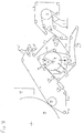
- Fig. 9 shows still another advanced dewatering system ADS for processing a fibrous web W.
- System ADS includes a fabric 4, a suction box 5, a vacuum roll 9, a dewatering fabric 7, a belt press assembly 18, a hood 11 (which may be a hot air hood), a pick up suction box 12, a Uhle box 6, one or more shower units 8, and one or more savealls 10.
- the fibrous material web W enters system ADS generally from the right as shown in Fig. 9 .
- the fibrous web W is a previously formed web (i.e., previously formed by a mechanism of the type described above) which is placed on the fabric 4.
- the suction device 5 provides suctioning to one side of the web W
- the suction roll 9 provides suctioning to an opposite side of the web W.
- the thickness of the vacuum roll shell of roll 9 may be in the range of between approximately 25 mm and approximately 75 mm.
- An airflow speed through the web W in the area of the suction zone Z is provided.
- the mean airflow through the web W in the area of the suction zone Z can be approximately 150 m 3 /min per meter machine width.
- the permeable belt 32 is a single endlessly circulating belt which is guided by a plurality of guide rolls and which presses against the vacuum roll 9 so as to form the belt press 18.
- the fabric 7 proceeds past one or more shower units 8. These units 8 apply moisture to the fabric 7 in order to clean the fabric 7.
- the fabric 7 then proceeds past a Uhle box 6, which removes moisture from fabric 7.
- the permeable belt 32 shown in Figs. 10-13 can of the same type as described above with regard to belt 32 of Figs. 1 and 3-8 and can provide a low level of pressing in the range of between approximately 30 KPa and approximately 150 KPa, and preferably greater than approximately 100 KPa.
- the suction roll 9 has a diameter of 1.2 meter
- the fabric tension for belt 32 can be greater than approximately 30 KN/m, and preferably greater than approximately 50 KN/m.
- the pressing length of permeable belt 32 against the fabric 4, which is indirectly supported by vacuum roll 9, can be at least as long as or longer than the circumferential length of the suction zone Z of roll 9.
- the invention also contemplates that the contact portion of permeable belt 32 (i.e., the portion of belt which is guided by or over the roll 9) can be shorter than suction zone Z.
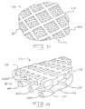
- the permeable belt 32 has a pattern 38 of through holes 36, which may, for example, be formed by drilling, laser cutting, etched formed, or woven therein.
- the permeable belt 32 may also be essentially monoplaner, i.e., formed without the grooves 40 shown in Figs. 11-13 .
- the surface of the belt 32 which has the grooves 40 can be placed in contact with the fabric 4 along a portion of the travel of permeable belt 32 in a belt press 18.
- Each groove 40 connects with a set or row of holes 36 so as to allow the passage and distribution of air in the belt 34. Air is thus distributed along grooves 40.
- the belt 32 can have the form of a polyurethane matrix 42 which has a permeable structure.
- the permeable structure can have the form of a woven structure with reinforcing machine direction yams 44 and cross direction yarns 46 at least partially embedded within polyurethane matrix 42.
- the belt 32 also includes through holes 36 and generally parallel longitudinal grooves 40 which connect the rows of openings as in the embodiment shown in Figs 11-13 .
- the openings 36 in every other row of openings can be offset by approximately half so that the longitudinal distance between adjacent openings can be half the distance between openings 36 of the same row, e.g., half of 6.5 mm.
- the overall width of the belt 32 can be approximately 1050 mm and the overall length of the endlessly circulating belt 32 can be approximately 8000 mm.
- the ADS utilizes belt press 182 to remove water from web W after the web is initially formed prior to reaching belt press 18.
- a permeable belt 32 is routed in the belt press 18 so as to engage a surface of fabric 4 and thereby press fabric 4 further against web W, thus pressing the web W against fabric 7, which is supported thereunder by a vacuum roll 7.
- the physical pressure applied by the belt 32 places some hydraulic pressure on the water in web W causing it to migrate toward fabrics 4 and 7.
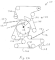
- Fig. 20 shows another an advanced dewatering system 110 for processing a fibrous web 112.
- the system 110 includes an upper fabric 114, a vacuum roll 118, a dewatering fabric 120, a belt press assembly 122, a hood 124 (which may be a hot air hood), a Uhle box 128, one or more shower units 130, one or more savealls 132, one or more heater units 129.
- the fibrous material web 112 enters system 110 generally from the right as shown in Fig. 12 .
- the fibrous web 112 is a previously formed web (i.e., previously formed by a mechanism not shown) which is placed on the fabric 114.
- a suction device (not shown but similar to device 16 in Fig. 9 ) can provide suctioning to one side of the web 112, while the suction roll 118 provides suctioning to an opposite side of the web 112.
- the fibrous web 112 is moved by fabric 114 in a machine direction M past one or more guide rolls. Although it may not be necessary, before reaching the suction roll, the web 112 may have sufficient moisture is removed from web 112 to achieve a solids level of between approximately 15% and approximately 25% on a typical or nominal 20 gram per square meter (gsm) web running. This can be accomplished by vacuum at a box (not shown) of between approximately -0.2 to approximately -0.8 bar vacuum, with a preferred operating level of between approximately -0.4 to approximately -0.6 bar.
- An airflow speed is provided through the web 112 in the area of the suction zone Z.
- the fabric 114, web 112 and dewatering fabric 120 is guided through a belt press 122 formed by the vacuum roll 118 and a permeable belt 134.
- the permeable belt 134 is a single endlessly circulating belt which is guided by a plurality of guide rolls and which presses against the vacuum roll 118 so as to form the belt press 122.
- a tension adjusting roll TAR is provided as one of the guide rolls.
- This mechanical pressure produces a predetermined hydraulic pressure in the web 112, whereby the contained water is drained.
- the upper fabric 114 has a bigger roughness and/or compressibility than the lower fabric 120.
- An airflow is caused in the direction from the at least one upper 114 to the at least one lower fabric 120 through the package of at least one upper fabric 114, at least one lower fabric 120 and the paper web 112 therebetween.
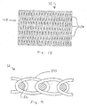
- the lower fabric 120 can be a membrane or fabric which includes a permeable base fabric BF and a lattice grid LG attached thereto and which is made of polymer such as polyurethane.
- the lattice grid LG side of the fabric 120 can be in contact with the suction roll 118 while the opposite side contacts the paper web 112.
- the lattice grid LG may be attached or arranged on the base fabric BF by utilizing various known procedures, such as, for example, an extrusion technique or a screen printing technique.
- the lattice grid LG can also be oriented at an angle relative to machine direction yarns MDY and cross-direction yarns CDY.
- Lattice grid LG can also be made of a synthetic, such as a polymer or specifically a polyurethane, which attaches itself to the base fabric BF by its natural adhesion properties.
- the lattice grid LG of a polyurethane provides it with good frictional properties, such that it seats well against the vacuum roll 118. This, then forces vertical airflow and eliminates any "x, y plane" leakage. The velocity of the air is sufficient to prevent any re-wetting once the water makes it through the lattice grid LG.
- the lattice grid LG may be a thin perforated hydrophobic film having an air permeability of approximately 177,8*10 -3 m 3 /m 2 /s (35 cfm) or less, preferably approximately 127*10 -3 m 3 /m 2 /s (25 cfm).
- the pores or openings of the lattice grid LG can be approximately 15 microns.
- the lattice grid LG can thus provide good vertical airflow at high velocity so as to prevent rewet. With such a fabric 120, it is possible to form or create a surface structure that is independent of the weave patterns.
- the lattice grid LG can itself include machine direction yarns GMDY with an elastomeric material EM being formed around these yarns.
- the lattice grid LG may thus be composite grid mat formed on elastomeric material EM and machine direction yarns GMDY.
- the grid machine direction yarns GMDY may be pre-coated with elastomeric material EM before being placed in rows that are substantially parallel in a mold that is used to reheat the elastomeric material EM causing it to re-flow into the pattern shown as grid LG in Fig. 22 . Additional elastomeric material EM may be put into the mold as well.
- the belt 120 shown in Figs. 21 and 22 can also be used in place of the belt 20 shown in the arrangement of Fig. 9 .
- FIG. 23 show an enlargement of one possible arrangement in a press.
- a suction support surface SS acts to support the fabrics 120, 114, 134 and the web 112.
- the suction support surface SS has suction openings SO.
- the suction surface SS is a jacket of the suction roll 118.
- the belt 134 can be a tensioned spiral link belt of the type already described herein.
- the belt 114 can be a structured fabric and the belt 120 can be a dewatering felt of the types described above. In this arrangement, moist air is drawn from above the belt 134 and through the belt 114, web 112, and belt 120 and finally through the openings SO and into the suction roll 118.
- Another possibility shown in Fig. 24 provides for the suction surface SS to be a jacket of the suction roll 118 and the belt 114 to be a SPECTRA membrane.
- the belt 134 can be a tensioned spiral link belt of the type already described herein.
- the belt 120 can be a dewatering felt of the types described above. In this arrangement, also moist air is drawn from above the belt 134 and through the belt 114, web 112, and belt 120 and finally through the openings SO and into the suction roll 118.
- Fig. 25 illustrates another way in which the web 112 can be subjecting to drying.
- a permeable support fabric SF (which can be similar to fabrics 20 or 120) is moved over a suction box SB.
- the suction box SB is sealed with seals S to an underside surface of the belt SF.
- a support belt 114 has the form of a TAD fabric and carries the web 112 into the press formed by the belt PF, and pressing device PD arranged therein, and the support belt SF and stationary suction box SB.
- the circulating pressing belt PF can be a tensioned spiral link belt of the type already described herein and/or of the type shown in Figs. 26 and 27 .
- the belt PF can also alternatively be a groove belt and/or it can also be permeable.
- the pressing device PD presses the belt PF with a pressing force PF against the belt SF while the suction box SB applies a vacuum to the belt SF, web 112 and belt 114.
- moist air can be drawn from at least the belt 114, web 112 and belt SF and finally into the suction box SB.
- the compressibility (thickness change by force in mm/N) of the upper fabric 114 is lower than that of the lower fabric 120. This is important in order to maintain the three-dimensional structure of the web 112, i.e., to ensure that the upper belt 114 is a stiff structure.
- the resilience of the lower fabric 120 should be considered.
- the density of the lower fabric 120 should be equal to or higher than approximately 0.4 g/cm 3 , and is preferably equal to or higher than approximately 0.5 g/cm 3 , and is ideally equal to or higher than approximately 0.53 g/cm 3 . This can be advantageous at web speeds of greater than 1200 m/min.
- a reduced felt volume makes it easier to take the water away from the felt 120 by the air flow, i.e., to get the water through the felt 120. Therefore the dewatering effect is smaller.
- Fig. 29 shows another an advanced dewatering system 310 for processing a fibrous web 312.
- the system 310 includes an upper fabric 314, a vacuum roll 318, a dewatering fabric 320 and a belt press assembly 322.
- Other optional features which are not shown include a hood (which may be a hot air hood), one or more Uhle boxes, one or more shower units, one or more savealls, and one or more heater units, as is shown in Figs. 9 and 20 .
- the fibrous material web 312 enters system 310 generally from the right as shown in Fig. 29 .
- the fibrous web 312 is a previously formed web (i.e., previously formed by a mechanism not shown) which is placed on the fabric 314.
- a suction device (not shown but similar to device 16 in Fig. 9 ) can provide suctioning to one side of the web 312, while the suction roll 318 provides suctioning to an opposite side of the web 312.
- the circumferential length of at least vacuum zone Z1 can be between approximately 200 mm and approximately 2500 mm, and is preferably between approximately 800 mm and approximately 1800 mm, and an even more preferably between approximately 1200 mm and approximately 1600 mm.
- the solids leaving vacuum roll 318 in web 312 will vary between approximately 25% to approximately 55% depending on the vacuum pressures and the tension on permeable belt 334 and the pressure from the pressing device RP as well as the length of vacuum zone Z1 and also Z2, and the dwell time of web 312 in vacuum zones Z1 and Z2.
- the dwell time of web 312 in vacuum zones Z1 and Z2 is sufficient to result in this solids range of between approximately 25% to approximately 55%.
- Figs. 28 and 29 have the following advantages: if a very high bulky web is not required, this option can be used to increase dryness and therefore production to a desired value, by adjusting carefully the mechanical pressure load. Due to the softer second fabric 220 or 320, the web 212 or 312 is also pressed at least partly between the prominent points (valleys) of the three-dimensional structure 214 or 314. The additional pressure field can be arranged preferably before (no re-wetting), after, or between the suction area.
- the upper permeable belt 234 or 334 is designed to resist a high tension of more than approximately 30 KN/m, and preferably approximately 50 KN/m, or higher e.g., approximately 80 KN/M.
Landscapes
- Paper (AREA)
- Woven Fabrics (AREA)
- Treatment Of Fiber Materials (AREA)
- Drying Of Solid Materials (AREA)
Description
- The invention an apparatus for drying a tissue or hygiene paper web that is less expensive, with regard to invested capital cost and ongoing operation costs, than a Through Air Drying process (TAD process). The apparatus according to the invention can easily be used to retrofit existing paper machines and can also be used for new machines. This can occur at a much lower cost that purchasing a new TAD machine. The quality of the web in terms of absorbency and calliper is made similar to that produced by the TAD process.
- In a wet pressing operation, a fibrous web sheet is compressed at a press nip to the point where hydraulic pressure drives water out of the fibrous web. It has been recognized that conventional wet pressing methods are inefficient in that only a small portion of a roll's circumference is used to process the paper web. To overcome this limitation, some attempts have been made to adapt a solid impermeable belt to an extended nip for pressing the paper web and dewater the paper web. A problem with such an approach is that the impermeable belt prevents the flow of a drying fluid, such as air through the paper web. Extended nip press (ENP) belts are used throughout the paper industry as a way of increasing the actual pressing dwell time in a press nip. A shoe press is the apparatus that provides the ability of the ENP belt to have pressure applied therethrough, by having a stationary shoe that is configured to the curvature of the hard surface being pressed, for example, a solid press roll. In this way, the nip can be extended 120 mm for tissue, up to 250 mm for flat papers beyond the limit of the contact between the press rolls themselves. An ENP belt serves as a roll cover on the shoe press. This flexible belt is lubricated on the inside by an oil shower to prevent frictional damage. The belt and shoe press are non-permeable members and dewatering of the fibrous web is accomplished almost exclusively by the mechanical pressing thereof.
- It is known in the prior art to utilize a through air drying process (TAD) for drying webs, especially tissue webs to reduce mechanical pressing. Huge TAD-cylinders are necessary, however, and as well as a complex air supply and heating system. This system requires a high operating expense to reach the necessary dryness of the web before it is transferred to a Yankee Cylinder, which drying cylinder dries the web to its end dryness of approximately 96%. On the Yankee surface, also, the creping takes place through a creping doctor.
- The machinery of the TAD system is a very expensive and costs roughly double that of a conventional tissue machine. Also, the operational costs are high, because with the TAD process, it is necessary to dry the web to a higher dryness level than it would be appropriate with the through air system in respect of the drying efficiency. The reason therefore is the poor CD moisture profile produced by the TAD system at low dryness level. The moisture CD profile is only acceptable at high dryness levels up to 60%. At over 30%, the impingement drying by the Hood/Yankee is much more efficient.
- The max web quality of a conventional tissue manufacturing process are as follows: the bulk of the produced tissue web is less than 9 cm3/g. The water holding capacity (measured by the basket method) of the produced tissue web is less than 9 (g H2O / g fiber).
- The advantage of the TAD system, however, results in a very high web quality especially with regard to high bulk of 10-16, water holding capacity of 10-16. With this high bulk, the jumbo roll weight is almost 60% of a conventional jumbo roll. Considering that 70% of the paper production cost are the fibers and that the capital investment for this machine is approximately 40% lower than for a TAD machine, the potential for this concept is evident.
- The patent
US 5,701,682 discloses a system for dewatering an embryonic web. The system consists of a roll with a capillary membrane arranged around the exterior surface of the roll. The web is supported on a knuckled through dryer fabric and lightly pressed between the knuckled through drier fabric and the capillary membrane. The capillary membrane has capillary pores therethrough which have a substantially straight through. Vacuum is applied inside of the roll. - The document
US 2003/0033727 A1 shows a method for drying fibrous webs utilizing a limiting orifice medium with a plurality of pores. The web is disposed on a supporting fluid permeable carrier. The web is pressed between the supporting carrier and the limiting orifice medium. A vacuum is drawn through the pores and the web greater than the breakthrough pressure of the pores of the medium. - The document
US 2003/0056925 A1 discloses an air press, a method for dewatering a fibrous web, an anti-rewet fabric and an anti-rewet felt for carrying the web through the air press. The anti-rewet fabric and the anti-rewet felt comprises at least one air distribution layer and a perforated film layer. - The invention of the document
US 6,051,105 provides a method for making a wet pressed paper web. An embryonic web of papermaking fibers is formed on a foraminous forming member, and transferred to an imprinting member to deflect a portion of the papermaking fibers in the embryonic web into deflection conduits in the imprinting member. The web and the imprinting member are then pressed in a compression nip with first, second, and third dewatering felt layers. - The
US 6,149,767 describes a method for making soft tissue. An uncreped tissue sheet having improved softness results from supplementally dewatering a wet web to a consistency of greater than about 30 percent using noncompressive dewatering techniques prior to a differential speed transfer and subsequent throughdrying. An air press particularly well suited for providing the supplemental noncompressive dewatering incorporates side and/or end seals to minimize escape of pressurized fluid. A creped tissue sheet can be produced with a variety of manufacturing benefits using the air press. - In the document
US 6,436,240 B1 a paper machine clothing is disclosed. The paper machine clothing comprises a base fabric comprising at least two superimposed perforated non-woven membranes, the upper or paper side one of which has a lower maximum creep modulus and is less hard than the lower or machine side membrane. - In the document
EP1293602 A1 a papermaking press felt is described. The papermaking press felt has excellent rewetting suppression without impaired water-squeezing capability. It comprises a base body, batt layers and a rewetting prevention layer, integrated with one another by needle punching. The rewetting prevention layer has three dimensional passages comprising a verge opening, a wet paper web side opening and a roll side opening. The wet paper web side opening is larger than the roll side opening. Under nip pressure, water moves from the wet paper web into the roll surface side of the felt, passing through the passages in the rewetting prevention layer. Although a rewetting phenomenon tends to occur when the press felt is released from the nip pressure, movement of water through the passages back to the wet paper web side of the felt is suppressed since the roll side openings are narrower than the wet paper web side opening. - A press felt for use in a paper machine is disclosed in the document
EP0878579 A2 . The felt includes a woven base fabric and a batt layer for supporting a paper web. A flow control layer is interposed between the base fabric and the fibrous batt layer to impede rewetting of the paper web as the paper web exits a press nip of the papermaking machine. The flow control layer is formed of a porous hydrophobic material. In use, pressure exerted by the press nip forces water from the paper web through the batt layer and the flow control layer into the base fabric and when the pressure is relieved, the hydrophobic properties of the flow control layer impede back-flow of water to the batt layer and thence to the paper web, thereby impeding rewetting of the web. A preferred flow control layer is formed of a spunbonded filamentary nylon material which is non-circular in cross-section, such as tri-lobed/triangular, and may be treated with a hydrophobic chemical composition to enhance its hydrophobic properties. The batt layer and the base layer are preferably secured into the felt by a needling process. - The patent
US 4,162,190 describes a paper making apparatus having a movable endless belt which conveys a wet web of paper between a pair of pressure rollers for driving water out of the web and then passing the web to a drying zone. A surface layer of the belt is formed from a water-absorbent nonwoven fiber material and a backing layer is provided which is coarser than the surface layer and is formed from water-absorbent wads of separate fibers. The surface layer has hydrophobic properties such that the surface layers has a critical surface tension less than 33 dynes per centimeter and is held in intimate contact with the backing layer by fibers of the surface layer which penetrate and are needled into the backing layer. The layers are thus so integrated that water forced into the surface layer by the pressure rollers is readily taken up by both layers to be retained thereby. -
WO 03/062528 US 2003/0136018 ), for example, disclose a method of making a three dimensional surface structured web wherein the web exhibits improved caliper and absorbency. This document discusses the need to improve dewatering with a specially designed advanced dewatering system.. The system uses an air press wich applies a load to the back side of the structured fabric during dewatering. - The wet molding process disclosed in
WO 03/062528 - The function of the TAD drum and the through-air system consists of drying the web and, for this reason, the above mentioned alternative drying apparatus (third pressure field) is preferable, since the third pressure field can be retrofitted to or included in a conventional machine at lower cost than TAD.
- To achieve the desired dryness, in accordance with an advantageous embodiment of the method disclosed therein, at least one felt with a foamed layer wrapping a suction roll is used for dewatering the web. In this connection, the foam coating can in particular be selected such that the mean pore size in a range from approximately 3 to approximately 6 µm results. The corresponding capillary action is therefore utilized for dewatering. The felt is provided with a special foam layer which gives the surface very small pores whose diameters can lie in the range set forth from approximately 3 to approximately 6 µm. The air permeability of this felt is very low. The natural capillary action is used for dewatering the web while this is in contact with the felt.
- In accordance with an advantageous embodiment of the method disclosed therein, a so-called SPECTRA membrane is used for dewatering the web, said SPECTRA membrane preferably being laminated or otherwise attached to an air distribution layer, and with this SPECTRA membrane preferably being used together with a conventional, in particular, woven, fabric. This document also discloses the use of an ant-rewetting membrane.
- The inventors have shown, that these suggested solutions, especially the use of the specially designed dewatering fabrics, improve the dewatering process, but the gains were not sufficient to support high speed operation. What is needed is a more efficient dewatering system, which is the subject of this disclosure,
- The present invention aims to improve the overall efficiency of the drying process, so that higher machine speeds can be realized and can be closer to the speeds of existing TAD machines. The invention also provides for an increased
pressure field 3, i.e., a main drying region of a press arrangement, so that the sheet or web exiting this region exits with a sheet solids level in a way that does not negatively impact sheet quality. - The aim is achieved by a system for drying a tissue or hygiene web, comprising: a permeable structured fabric for making a three dimensional surface structured web, carrying the web over a drying apparatus comprising a vacuum roll; a permeable dewatering fabric contacting the web and being guided over the drying apparatus; and a mechanism for applying pressure to the permeable structured fabric, the web, and the permeable dewatering fabric at the drying apparatus. According to the invention, mechanical pressure is applied by the mechanism for applying pressure, the mechanism comprising a belt press comprising a permeable belt as pressing element and whereby the system is structured and arranged to cause an air flow first through the permeable structured fabric, then through the web, then through the permeable dewatering fabric and into drying apparatus and allowing a simultaneous vacuum and pressing dewatering with airflow through the web at the press nip itself.
- Further features of the system according to the invention are defined in the dependent claims.
- Non-limiting examples or aspects of the dewatering fabric are as follows. One preferred structure is a traditional needle punched press fabric, with multiple layers of bat fiber, wherein the bat fiber ranges from between approximately 0.5 dtex to approximately 22 dtex. The dewatering fabric can include a combination of different dtex fibers. It can also preferably contain an adhesive to supplement fiber to fiber or fiber to substructure (base cloth) or particle to fiber or particle to substructure (base cloth) bonding, for example, low melt fibers or particles, and/or resin treatments. Acceptable bonding with melting fibers can be achieved by using adhesive which is equal to or greater than approximately 1 % of the total cloth weight, preferably equal to or greater than approximately 3%, and most preferably equal to or greater than approximately 5%. These melting fibers, for example, can be made from one component or can contain two or more components. All of these fibers can have different shapes and at least one of these components can have an essentially lower melting point than the standard material for the cloth. The dewatering fabric may be a thin structure which is preferably less than approximately 1.50 mm thick, or more preferably less than approximately 1.25 mm, and most preferably less than approximately 1.0 mm. The dewatering fabric can include weft yarns which can be multifilament yarns usually twisted/plied. The weft yarns can also be solid mono strands usually less than approximately 0.30 mm diameter, preferably approximately 0.20 mm in diameter, or as low as approximately 0.10 mm in diameter. The weft yarns can be a single strand, twisted or cabled, or joined side by side, or a flat shape. The dewatering fabric can also utilize warp yarns which are monofilament and which have a diameter of between approximately 0.30 mm and approximately 0.10 mm. They may be twisted or single filaments which can preferably be approximately 0.20 mm in diameter. The dewatering fabric can be needled punched with straight through drainage channels, and may preferably utilize a generally uniform needling. The dewatering fabric can also include an optional thin hydrophobic layer applied to one of its surfaces with, e.g., an air perm of between approximately 25,4*10-3 m3/m2/s (5 cfm) to approximately 508*10-3 m3/m2/s (100 cfm), and preferably approximately 96.52*10-3 m3/m2/s (19 cfm) or higher, most preferably approximately 77,8*10-3 m3/m2/s (35 cfm) or higher. The mean pore diameter can be in the range of between approximately 5 to approximately 75 microns, preferably approximately 25 microns or higher, more preferably approximately 35 microns or higher. The dewatering fabric can be made of various synthetic polymeric materials, or even wool, etc., and can preferably be made of polyamides such as, e.g.,
Nylon 6. - An alternative structure for the dewatering fabric can be a woven. base cloth laminated to an anti-rewet layer. The base cloth is woven endless structure using between approximately 0.10 mm and approximately 0.30 mm, and preferably approximately 0.20 mm diameter monofilament warp yarns (cross machine direction yarns on the paper machine) and a combination multifilament yarns usually twisted/plied. The yarns can also be solid mono strands usually less than approximately 0.30 mm diameter, preferably approximately 0.20 mm in diameter, or as low as approximately 0.10 mm in diameter. The weft yarns can be a single strand, twisted or cabled, joined side by side, or a flat shape weft (machine direction yarns on the paper machine). The base fabric can be laminated to an anti-rewet layer, which preferably is a thin elastomeric cast permeable membrane. The permeable membrane can be approximately 1.05 mm thick, and preferably less than approximately 1.05 mm. The purpose of the thin elastomeric cast membrane is to prevent sheet rewet by providing a buffer layer of air to delay water from traveling back into the sheet, since the air needs to be moved before the water can reach the sheet. The lamination process can be accomplished by either melting the elastomeric membrane into the woven base cloth, or by needling two or less thin layers of bat fiber on the face side with two or less thin layers of bat fiber on the back side to secure the two layers together. An optional thin hydrophobic layer can be applied to the surface. This optional layer can have an air perm of approximately 660*10-3 m3/m2/s (130 cfm) or lower, preferably approximately 508*10-3 m3/m2/s (100 cfm) or lower, and most preferably approximately 406,4*10-3 m3/m2/s (80 cfm) or lower. The belt may have a mean pore diameter of approximately 140 microns or lower, more preferably
approximately 100 microns or lower, and most preferably approximately 60 microns or lower. - Another alternative structure for the dewatering fabric utilizes an anti-rewet membrane which includes a thin woven multifilament textile cloth laminated to a thin perforated hydrophobic film, with an air perm of 177,8*10-3 m3/m2/s (35 cfm) or less, preferably 127*10-3 m3/m2/s (25 cfm) or less, with a mean pore size of 15 microns. According to a further preferred embodiment of the invention, the dewatering fabric is a felt with a batt layer. The diameter of the batt fibers of the lower fabric are equal to or less than approximately 11 dtex, and can preferably be equal to or lower than approximately 4.2 dtex, or more preferably be equal to or less than approximately 3.3 dtex. The batt fibers can also be a blend of fibers. The dewatering fabric can also contain a vector layer which contains fibers from approximately 67 dtex, and can also contain even courser fibers such as, e.g., approximately 100 dtex, approximately 140 dtex, or even higher dtex numbers. This is important for the good absorption of water. The wetted surface of the batt layer of the dewatering fabric and/or of the dewatering fabric itself can be equal to or greater than approximately 35 m2/m2 felt area, and can preferably be equal to or greater than approximately 65 m2/m2 felt area, and can most preferably be equal to or greater than approximately 100 m2/m2 felt area. The specific surface of the dewatering fabric should be equal to or greater than approximately 0.04 m2/g felt weight, and can preferably be equal to or greater than approximately 0.065 m2/g felt weight, and can most preferably be equal to or greater than approximately 0.075 m2/g felt weight. This is important for the good absorption of water. The dynamic stiffness K* [N/mm] as a value for the compressibility is acceptable if less than or equal to 100,000 N/mm, preferable compressibility is less than or equal to 90,000 N/mm, and most preferably the compressibility is less than or equal to 70,000 N/mm. The compressibility (thickness change by force in mm/N) of the dewatering fabric is higher than that of the upper fabric. This is also important in order to dewater the web efficiently to a high dryness level.
- The dewatering fabric may also preferably utilize vertical flow channels. These can be created by printing polymeric materials on to the fabric. They can also be created by a special weave pattern which uses low melt yarns that are subsequently thermoformed to create channels and air blocks to prevent leakage. Such structures can be needle punched to provide surface enhancements and wear resistance.
- The fabrics used for the dewatering fabric can also be seamed/joined on the machine socked on when the fabrics are already joined. The on-machine seamed/joined method does not interfere with the dewatering process.
- The surface of the dewatering fabrics described in this application can be modified to alter surface energy. They can also have blocked in-plane flow properties in order to force exclusive z-direction flow.
- The invention also takes advantage of the fact that the mass of fibers remain protected within the body (valleys) of the structured fabric and there is only a slightly pressing which occurs between the prominent points of the structured fabric (valleys). These valleys are no too deep so as to avoid deforming the fibers of the sheet plastically and to avoid negatively impacting the quality of the paper sheet, but no so shallow so as to take-up the excess water out of the mass of fibers. Of course, this is dependent on the softness, compressibility and resilience of the dewatering fabric.
- The permeable dewatering fabric may comprise a needle punched press fabric with multiple layers of bat fiber. The permeable dewatering fabric mat comprise a needle punched press fabric with multiple layers of bat fiber, and wherein the bat fiber ranges from between approximately 0.5 dtex to approximately 22 dtex. The permeable dewatering fabric may comprise a combination of different dtex fibers. According to a further preferred embodiment of the invention, the permeable dewatering fabric is a felt with a batt layer. The diameter of the batt fibers of the lower fabric are equal to or less than approximately 11 dtex, and can preferably be equal to or lower than approximately 4.2 dtex, or more preferably be equal to or less than approximately 3.3 dtex. The batt fibers can also be a blend of fibers. The permeable dewatering fabric can also contain a vector layer which contains fibers from approximately 67 dtex, and can also contain even courser fibers such as, e.g., approximately 100 dtex, approximately 140 dtex, or even higher dtex numbers. This is important for the good absorption of water. The wetted surface of the batt layer of the permeable dewatering fabric and/or of the permeable dewatering fabric itself can be equal to or greater than approximately 35 m2/m2 felt area, and can preferably be equal to or greater than approximately 65 m2/m2 felt area, and can most preferably be equal to or greater than approximately 100 m2/m2 felt area. The specific surface of the permeable dewatering fabric should be equal to or greater than approximately 0.04 m2/g felt weight, and can preferably be equal to or greater than approximately 0.065 m2/g felt weight, and can most preferably be equal to or greater than approximately 0.075 m2/g felt weight. This is important for the good absorption of water. The dynamic stiffness K* [N/mm] as a value for the compressibility is acceptable if less than or equal to 100,000 N/mm, preferable compressibility is less than or equal to 90,000 N/mm, and most preferably the compressibility is less than or equal to 70,000 N/mm. The compressibility (thickness change by force in mm/N) of the permeable dewatering fabric is higher than that of the upper fabric. This is also important in order to dewater the web efficiently to a high dryness level.
- The permeable dewatering fabric may comprise batt fibers and an adhesive to supplement fiber to fiber bonding. The permeable dewatering fabric may comprise batt fibers which include at least one of low melt fibers or particles and resin treatments. The permeable dewatering fabric may comprise a thickness of less than approximately 1.50 mm thick. The permeable dewatering fabric may comprise a thickness of less than approximately 1.25 mm thick. The permeable dewatering fabric may comprise a thickness of less than approximately 1.00 mm thick.
- The permeable dewatering fabric may comprise weft yarns. The weft yarns may comprise multifilament yarns which are twisted or plied. The weft yarns may comprise solid mono strands which are less than approximately 0.30 mm diameter. The weft yarns may comprise solid mono strands which are less than approximately 0.20 mm diameter. The weft yarns may comprise solid mono strands which are less than approximately 0.10 mm diameter. The weft yarns may comprise one of single strand yarns, twisted yarns, cabled yarns, yarns which are joined side by side, and yarns which are generally flat shaped.
- The permeable dewatering fabric may comprise warp yarns. The warp yarns may comprise monofilament yarns having a diameter of between approximately 0.30 mm and approximately 0.10 mm. The warp yarns may comprise twisted or single filaments which are approximately 0.20 mm in diameter. The permeable dewatering fabric may be needled punched and may include straight through drainage channels. The permeable dewatering fabric may be needled punched and utilizes a generally uniform needling. The permeable dewatering fabric may comprise a base fabric and a thin hydrophobic layer applied to a surface of the base fabric. The permeable dewatering fabric may comprise an air permeability of between approximately 25,4*10-3 m3/m2/s (5 cfm) to approximately 508*10-3 m3/m2/s (100 cfm). The permeable dewatering fabric may comprise an air permeability which is approximately 96,52*10-3 m3/m2/s (19 cfm) or higher. The permeable dewatering fabric may comprise an air permeability which is approximately 177,8*10-3 m3/m2/s (35 cfm) or higher. The permeable dewatering fabric may comprise a mean pore diameter in the range of between approximately 5 to approximately 75 microns. The permeable dewatering fabric may comprise a mean pore diameter which is approximately 25 microns or higher. The permeable dewatering fabric may comprise a mean pore diameter which is approximately 35 microns or higher.
- The permeable dewatering fabric may comprise at least one synthetic polymeric material. The permeable dewatering fabric may comprise wool. The permeable dewatering fabric may comprise a polyamide material. The polyamide material may be
Nylon 6. The permeable dewatering fabric may comprise a woven base cloth which is laminated to an anti-rewet layer. The woven base cloth may comprise a woven endless structure which includes monofilament warp yarns having a diameter of between approximately 0.10 mm and approximately 0.30 mm. The diameter may be approximately 0.20 mm. The woven base cloth may comprise a woven endless structure which includes multifilament yarns which are twisted or plied. The woven base cloth may comprise a woven endless structure which includes multifilament yarns which are solid mono strands of less than approximately 0.30 mm diameter. The solid mono strands may be approximately 0.20 mm diameter. The solid mono strands may be approximately 0.10 mm diameter. - The woven base cloth may comprises a woven endless structure which includes weft yarns. The weft yarns may comprise one of single strand yarns, twisted or cabled yarns, yarns which are joined side by side, and flat shape weft yarns. The permeable dewatering fabric may comprise a base fabric layer and an anti-rewet layer. The anti-rewet layer may comprise a thin elastomeric cast permeable membrane. The elastomeric cast permeable membrane may be equal to or less than approximately 1.05 mm thick. The elastomeric cast permeable membrane may be adapted to form a buffer layer of air so as to delay water from traveling back into the web. The anti-rewet layer and the base fabric layer may be connected to each other by lamination.
- With the system according to the invention, there is no need for through air drying. A paper having the same quality as produced on a TAD machine is generated with the inventive system utilizing the whole capability of impingement drying which is more efficient in drying the sheet from about 35% to more than about 90% solids.
- The above-mentioned and other features and advantages of this invention, and the manner of attaining them, will become more apparent and the invention will be better understood by reference to the following description of an embodiment of the invention taken in conjunction with the accompanying drawings, wherein:
-
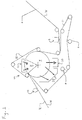
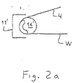
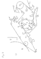
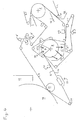
Figs. 1, 2, 2a and 3-8 shows cross-sectional schematic diagrams of various embodiments of advanced dewatering systems, wherein the embodiment according toFig.2 does not fall within the scope of the appended claims; -
Fig. 9 is a cross-sectional schematic diagram of an advanced dewatering system with an embodiment of a belt press according to the present invention; -
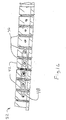
Fig. 10 is a surface view of one side of a permeable belt of the belt press ofFig. 9 ; -
Fig. 11 is a view of an opposite side of the permeable belt ofFig. 10 ; -
Fig. 12 is cross-section view of the permeable belt ofFigs. 10 and11 ; -
Fig. 13 is an enlarged cross-sectional view of the permeable belt ofFigs. 10-12 ; -
Fig. 13a is an enlarged cross-sectional view of the permeable belt ofFigs. 10-12 and illustrating optional triangular grooves; -
Fig. 13b is an enlarged cross-sectional view of the permeable belt ofFigs. 10-12 and illustrating optional semi-circular grooves; -
Fig. 13c is an enlarged cross-sectional view of the permeable belt ofFigs. 10-12 illustrating optional trapezoidal grooves; -
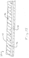
Fig. 14 is a cross-sectional view of the permeable belt ofFig. 11 along section line B-B; -
Fig. 15 is a cross-sectional view of the permeable belt ofFig. 11 along section line A-A; -
Fig. 16 is a cross-sectional view of another embodiment of the permeable belt ofFig. 11 along section line B-B; -
Fig. 17 is a cross-sectional view of another embodiment of the permeable belt ofFig. 11 along section line A-A; -
Fig. 18 is a surface view of another embodiment of the permeable belt of the present invention; -
Fig. 19 is a side view of a portion of the permeable belt ofFig. 18 ; -
Fig. 20 is a cross-sectional schematic diagram of still another advanced dewatering system with an embodiment of a belt press according to the present invention; -
Fig. 21 is an enlarged partial view of one dewatering fabric which can be used on the advanced dewatering systems of the present invention; -
Fig. 22 is an enlarged partial view of another dewatering fabric which can be used on the advanced dewatering systems of the present invention; -
Fig. 23 is a exaggerated cross-sectional schematic diagram of one embodiment of a pressing portion of the advanced dewatering system according to the present invention; -
Fig. 24 is a exaggerated cross-sectional schematic diagram of another embodiment of a pressing portion of the advanced dewatering system according to the present invention; -
Fig. 25 is a cross-sectional schematic diagram of still another advanced dewatering system with another embodiment of a belt press, which does not fall within the scope of the appended claims; -
Fig. 26 is a partial side view of an optional permeable belt which may be used in the advanced dewatering systems of the present invention; -
Fig. 27 is a partial side view of another optional permeable belt which may be used in the advanced dewatering systems of the present invention; -
Fig. 28 is a cross-sectional schematic diagram of still another advanced dewatering system with an embodiment of a belt press which uses a pressing shoe according to the present invention; -
Fig. 29 is a cross-sectional schematic diagram of still another advanced dewatering system with an embodiment of a belt press which uses a press roll according to the present invention; -
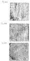
Fig. 30a illustrates an area of an Ashworth metal belt which can be used in the invention. The portions of the belt which are shown in black represent the contact area whereas the portions of the belt shown in white represent the non-contact area; -
Fig. 30b illustrates an area of a Cambridge metal belt which can be used in the invention. The portions of the belt which are shown in black represent the contact area whereas the portions of the belt shown in white represent the non-contact area; and -
Fig. 30c illustrates an area of a Voith Fabrics link fabric which can be used in the invention. The portions of the belt which are shown in black represent the contact area whereas the portions of the belt shown in white represent the non-contact area. - Corresponding reference characters indicate corresponding parts throughout the several views. The exemplary embodiments set out herein illustrate one or more acceptable or preferred embodiments of the invention, and such exemplifications are not to be construed as limiting the scope of the invention in any manner.
- The particulars shown herein are by way of example and for purposes of illustrative discussion of the embodiments of the present invention only and are presented in the cause of providing what is believed to be the most useful and readily understood description of the principles and conceptual aspects of the present invention. In this regard, no attempt is made to show structural details of the present invention in more detail than is necessary for the fundamental understanding of the present invention, the description is taken with the drawings making apparent to those skilled in the art how the forms of the present invention may be embodied in practice.
- Referring now to the drawings,
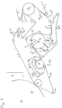
Fig. 1 shows a diagram of the Advanced Dewatering System (ADS) that utilizes a main pressure field in the form of abelt press 18. A formed web W is carried by astructured fabric 4 to a vacuum box 5 that is required to achieve a solids level of between approximately 15% and approximately 25% on a nominal 20 gsm web running at between approximately -0.2 and approximately -0.8 bar vacuum, and can preferred operate at a level of between approximately -0.4 and approximately -0.6 bar. Avacuum roll 9 is operated at a vacuum level of between approximately -0.2 and approximately -0.8 bar, preferably it is operated at a level of approximately -0.4 bar or higher. Thebelt press 18 includes asingle fabric run 32 capable of applying pressure to the non-sheet contacting side of thestructured fabric 4 that carries the web W around thesuction roll 9. Thefabric 32 is a continuous or endless circulating belt that guided around a plurality of guide rolls and is characterized by being permeable. An optionalhot air hood 11 is arranged within thebelt 32 and is positioned over thevacuum roll 9 in order to improve dewatering. Thevacuum roll 9 includes at least one vacuum zone Z and has circumferential length of between approximately 200 mm and approximately 2500 mm, preferably between approximately 800 mm and approximately 1800 mm, and more preferably between approximately 1200 mm and approximately 1600 mm. The thickness of the vacuum roll shell can preferably be in the range of between approximately 25 mm and approximately 75 mm. The mean airflow through theweb 112 in the area of the suction zone Z can be approximately 150 m3/min per meter machine width. The solid level leaving thesuction roll 9 is between approximately 25% and approximately 55% depending on the installed options, and is preferably greater than approximately 30%, is more preferably greater than approximately 35%, and is even more preferably greater than approximately 40%. An optional pick upvacuum box 12 can be used to make sure that the sheet or web W follows the structuredfabric 4 and separates from adewatering fabric 7. It should be noted that the direction of air flow in a first pressure field (i.e., vacuum box 5) and the main pressure field (i.e., formed by vacuum roll 9) are opposite to each other. The system also utilizes one oremore shower units 8 and one ormore Uhle boxes 6. - There is a significant increase in dryness with the
belt press 18. Thebelt 32 should be capable of sustaining an increase in belt tension of up to approximately 80 KN/m without being destroyed and without destroying web quality. There is roughly about a 2% more dryness in the web W for each tension increase of 20 KN/m. A synthetic belt may not achieve a desired file force of less than approximately 45 KN/m and the belt may stretch too much during running on the machine. For this reason, thebelt 32 can, for example, be a pin seamable belt, a spiral link fabric, and possibly even a stainless steel metal belt. - The
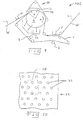
permeable belt 32 can have yarns interlinked by entwining generally spiral woven yarns with cross yarns in order to form a link fabric. Non-limiting examples of this belt can include a Ashworth Metal Belt, a Cambridge Metal belt and a Voith Fabrics Link Fabric and are shown inFigs. 30a-c . The spiral link fabric described in this specification can also be made of a polymeric material and/or is preferably tensioned in the range of between approximately 30 KN/m and 80 KN/m, and preferably between approximately 35 KN/m and approximately 50 KN/m. This provides improved runnability of the belt, which is not able to withstand high tensions, and is balanced with sufficient dewatering of the paper web.Fig. 30a illustrates an area of the Ashworth metal belt which is acceptable for use in the invention. The portions of the belt which are shown in black represent the contact area whereas the portions of the belt shown in white represent the non-contact area. The Ashworth belt is a metal link belt which is tensioned at approximately 60 KN/m. The open area may be between approximately 75% and approximately 85%. The contact area may be between approximately 15% and approximately 25%.Fig. 30b illustrates an area of a Cambridge metal belt which is preferred for use in the invention. Again, the portions of the belt which are shown in black represent the contact area whereas the portions of the belt shown in white represent the non-contact area. The Cambridge belt is a metal link belt which is tensioned at approximately 50 KN/m. The open area may be between approximately 68% and approximately 76%. The contact area may be between approximately 24% and approximately 32%. Finally,Fig. 30c illustrates an area of a Voith Fabrics link fabric which is most preferably used in the invention. The portions of the belt which are shown in black represent the contact area whereas the portions of the belt shown in white represent the non-contact area. The Voith Fabrics belt may be a polymer link fabric which is tensioned at approximately 40 KN/m. The open area may be between approximately 51% and approximately 62%. The contact area may be between approximately 38% and approximately 49%. - The
dewatering fabric 7 can be of a very thin construction, which reduces the amount of water being carried by an order of magnitude to improve dewatering efficiency and reduce / eliminate the rewetting phenomena seen with prior art structures. However, there does not appear to any gain in dryness in a belt press which presses over a thin anti-rewet membrane. Thicker and softer belt structures benefit more from the belt press. A needle batt structure felt may be a better option for thebelt 7. By heating thedewatering fabric 7 to as much as approximately 50 degrees C, it is possible to achieve as much as approximately 1.5% more dryness. For all dwell times above approximately 50 ms, the dwell time does not appear to affect dryness, and the higher the vacuum level in theroll 9, the higher the dryness of the web W. - As regards the fiber suspension used for the web W, there can also be a significant gain in dryness by using a high consistency refiner versus a low consistency refiner. A lower SR degree, less fines, more porosity results in better a dewatering capability. There can also be advantageous in using the right furnish. By running comparison trials between high consistency refining (approximately 30% consistency) and low consistency refining (approximately 4.5% consistency), the inventors were able to achieve the same tensile strength needed for tissue towel paper, but with less refining degree. The same tensile strength was achieved by refining 100% softwood to 17 SR instead of 21 SR, i.e., it resulted in approximately 4 degrees less Schopper Riegler. By comparing high consistency refining to low consistency refining at the same refining degree, i.e., at 17 SR, the inventors were able to achieve 30% more tensile strength with the high consistency refining. The high consistency refining was accomplished with a thickener, which can be a wire press or a screw press, followed by a disc dispenser with a refining filling. This is possible for tissue papers because the required tensile strength is low. To reach the tensile target for towel paper, the inventors used two passes through the disc dispenser. The big advantage of the above-noted process is to reduce refining, thus resulting in less fines, lower WRV (water retention value), more porosity and better dewatering capability for the ADS concept. With better dewatering capacity it is possible to increase machine speed, and in addition, the lower refining degree increases paper quality.
- Embodiments of the main pressure field include a suction roll or a suction box. Non-limiting examples of such devices are described herein. The mean airflow speed through the sheet or web in the main pressure field is preferably approximately 6 m/s.
- Non-limiting examples or aspects of the
dewatering fabric 7 will now be described. One preferred structure is a traditional needle punched press fabric, with multiple layers of bat fiber, wherein the bat fiber ranges from between approximately 0.5 dtex to approximately 22 dtex. Thebelt 7 can include a combination of different dtex fibers. It can also preferably contain an adhesive to supplement fiber to fiber bonding, for example, low melt fibers or particles, and/or resin treatments. Thebelt 7 may be a thin structure which is preferably less than approximately 1.50 mm thick, or more preferably less than approximately 1.25 mm, and most preferably less than approximately 1.0 mm. Thebelt 7 can include weft yarns which can be multifilament yarns usually twisted/plied. The weft yarns can also be solid mono strands usually less than approximately 0.30 mm diameter, preferably approximately 0.20 mm in diameter, or as low as approximately 0.10 mm in diameter. The weft yarns can be a single strand, twisted or cabled, or joined side by side, or a flat shape. Thebelt 7 can also utilize warp yarns which are monofilament and which have a diameter of between approximately 0.30 mm and approximately 0.10 mm. They may be twisted or single filaments which can preferably be approximately 0.20 mm in diameter. Thebelt 7 can be needled punched with straight through drainage channels, and may preferably utilize a generally uniform needling. Thebelt 7 can also include an optional thin hydrophobic layer applied to one of its surfaces with, e.g., an air perm of between approximately 25,4*10-3 m3/m2/s (5 cfm) to approximately 508*10-3 m3/m2/s (100 cfm), and preferably approximately 96,52*10-3 m3/m2/s (19 cfm) or higher, most preferably approximately 177*10-3 m3/m2/s (35 cfm) or higher. The mean pore diameter can be in the range of between approximately 5 to approximately 75 microns, preferably approximately 25 microns or higher, more preferably approximately 35 microns or higher. Thebelt 7 can be made of various synthetic polymeric materials, or even wool, etc., and can preferably be made of polyamides such as, e.g.,Nylon 6. - An alternative structure for the
belt 7 can be a woven base cloth laminated to an anti-rewet layer. The base cloth is woven endless structure using between approximately 0.10 mm and approximately 0.30 mm, and preferably approximately 0.20 mm diameter monofilament warp yarns (cross machine direction yarns on the paper machine) and a combination multifilament yarns usually twisted/plied. The yarns can also be solid mono strands usually less than approximately 0.30 mm diameter, preferably approximately 0.20 mm in diameter, or as low as approximately 0.10 mm in diameter. The weft yarns can be a single strand, twisted or cabled, joined side by side, or a flat shape weft (machine direction yarns on the paper machine). The base fabric can be laminated to an anti-rewet layer, which preferably is a thin elastomeric cast permeable membrane. The permeable membrane can be approximately 1.05 mm thick, and preferably less than approximately 1.05 mm. The purpose of the thin elastomeric cast membrane is to prevent sheet rewet by providing a buffer layer of air to delay water from traveling back into the sheet, since the air needs to be moved before the water can reach the sheet. The lamination process can be accomplished by either melting the elastomeric membrane into the woven base cloth, or by needling two or less thin layers of bat fiber on the face side with two or less thin layers of bat fiber on the back side to secure the two layers together. An optional thin hydrophobic layer can be applied to the surface. This optional layer can have an air perm of approximately 660*10-3 m3/m2/s (130 cfm) or lower, preferably approximately 508*10-3 m3/m2/s (100 cfm) or lower, and most preferably approximately
406,4*10-3 m3/m2/s (80 cfm) or lower. Thebelt 7 may have a mean pore diameter of approximately 140 microns or lower, more preferably approximately 100 microns or lower, and most preferably approximately 60 microns or lower. - Another alternative structure for the
belt 7 utilizes an anti-rewet membrane which includes a thin woven multifilament textile cloth laminated to a thin perforated hydrophobic film, with an air perm of 177,8*10-3 m3/m2/s (35 cfm) or less, preferably 127*10-3 m3/m2/s (25 cfm) or less, with a mean pore size of 15 microns. - The belt may also preferably utilize vertical flow channels. These can be created by printing polymeric materials on to the fabric. They can also be created by a special weave pattern which uses low melt yarns that are subsequently thermoformed to create channels and air blocks to prevent leakage. Such structures can be needle punched to provide surface enhancements and wear resistance.
- The fabrics used for the
belt 7 can also be seamed/joined on the machine socked on when the fabrics are already joined. The on-machine seamed/joined method does not interfere with the dewatering process. - The surface of the
fabrics 7 described in this application can be modified to alter surface energy. They can also have blocked in-plane flow properties in order to force exclusive z-direction flow. -
Fig. 1 can also have the following configuration. Abelt press 18 fits over thevacuum roll 9. Apermeable fabric 32 run is capable of applying pressure to the non-sheet contacting side of thestructured fabric 4 that carries the web W around thesuction roll 9. Thesingle fabric 32 is characterized by being permeable. An optionalhot air hood 11 is fit over thevacuum roll 9 inside thebelt press 18 to improve dewatering. Thepermeable fabric 32 used in thebelt press 18 is a specially designed Extended Nip Press (ENP) belt, for example a flexible reinforced polyurethane belt, which provides a low level of pressing in the range of between approximately 30 to approximately 150 KPa, and preferably greater than approximately 100 KPa. This means, for example, for asuction roll 9 with a diameter of approximately 1.2 meters, the fabric tension ofbelt 32 can be greater than approximately 30 KN/m, and preferably greater than approximately 50 KN/m. The pressing length can be shorter, equal to, or longer the circumferential length of the suction zone Z of theroll 9. TheENP belt 32 can have grooves or it can have a monoplaner surface. Thefabric 32 can have a drilled hole pattern, so that the sheet W is impacted with both pressing and vacuum with air flow simultaneously. The combination has been shown to increase sheet solids by as much as approximately 15%. The specially designed ENP belt is only an example of a particular fabric that can be used for this process and is by no means the only type of structure that can be used. One essential feature of thepermeable fabric 32 for thebelt press 18 is a fabric that can run at abnormally high running tension (i.e., approximately 50 KN/m or higher) with relatively high surface contact area (i.e., approximately 10 % or 25% or greater) and a high open area (i.e., approximately 25% or greater). - An example of another option for
belt 32 is a thin spiral link fabric. The spiral link fabric can be used alone as thefabric 32 or, for example, it can be arranged inside the ENP belt. As described above, thefabric 32 rides over thestructured fabric 4 applying pressure thereon. The pressure is then transmitted through thestructured fabric 4 which is carrying the web W. The high basis weight pillow areas of the web W are protected from this pressure as they are within the body of thestructured fabric 4. Therefore, this pressing process does not impact negatively on web quality, but increases the dewatering rate of the suction roll. Thebelt 32 used in the belt press shown inFig. 1 can also be of the type used in the belt presses described with regard toFigs. 9-28 herein. - The invention also provides that the
suction roll 9 can be arranged between the former and a Yankee roll. The sheet or web W is carried around thesuction roll 9. The roll has aseparate fabric 32 which runs with a specially designeddewatering fabric 7. It could also have a second fabric run below thedewatering fabric 7 to further disperse the air. The web W comes in contact with thedewatering fabric 7 and is dewatering sufficiently to promote transfer to a hot Yankee / Hood for further drying and subsequent creping.Fig 2 shows several of the possible add-on options to enhance the process. However, it is by no means is a complete list, and is shown for demonstrations purposes only. An aspect of the invention provides for forming a light weight tissue web on a structured fabric 4 (which can also be a an imprinting or TAD fabric) and providing such a web W with sufficient solids to affect transfer to the Yankee Dryer for subsequent drying, creping, and reeling up. - Referring back to
Fig. 2 (which shows an embodiment which does not fall within the scopeof the appended claims), a vacuum box 5 is utilized to achieve a solids level of between approximately 15% and approximately 25% on a nominal 20 gsm web W running at between approximately -0.2 bar to approximately -0.8 bar vacuum, and can preferably operate at a level of between approximately -0.4 bar and approximately -0.6 bar. Thevacuum roll 9 is operated at a vacuum level of between approximately -0.2 bar to approximately - 0.8 bar, and is preferably operated at a level of between approximately -0.4 bar or higher. An optionalhot air hood 11 is fit over thevacuum roll 9 to improve dewatering. The circumferential length of the vacuum zone Z inside thevacuum roll 9 can be from between approximately 200 mm to approximately 2500 mm, is preferably between approximately 800 mm and approximately 1800 mm, and is more preferably between approximately 1200 mm and approximately 1600 mm. By way on non-limiting example, the thickness of the vacuum roll shell can preferably be in the range of between approximately 25 mm and approximately 75 mm. The mean airflow through theweb 112 in the area of the suction zone Z can be approximately 150 m3/min per meter machine width. The solids leaving thesuction roll 9 can be between approximately 25% to approximately 55% depending on the installed options, and is preferably greater than approximately 30%, even more preferably greater than approximately 35%, and most preferably greater than approximately 40%. - An
optional vacuum box 12 can be used to ensure that the sheet or web W follows the structuredfabric 4 after thevacuum roll 9. An optional vacuum box with hotair supply hood 13 could also be used to increase sheet solids after thevacuum roll 9 and before aYankee cylinder 16. Awire turning roll 14 can also be utilized. As can be seen inFig. 2a , theroll 14 can be a suction turning roll with hot air supply hood 11'. By way of non-limiting example, thestandard pressure roll 15 can also be a shoe press with shoe width of approximately 80 mm or higher, and is preferably approximately 120 mm or higher, and it may utilize a maximum peak pressure which is preferably less than approximately 2.5 MPa. To create an even longer nip, in order to facilitate web transfer to the Yankee roll 16 from thebelt 4, the web W with thestructured fabric 4 is brought into contact with a surface of theYankee roll 16 prior to the press nip formed by theroll 15 and theYankee roll 16. Alternatively, thestructured fabric 4 can be in contact with the surface of theYankee roll 16 for some distance following the press nip formed by theroll 15 and theYankee roll 16. According to another alternative possibility, both or the combination of these features can be utilized. - As can be seen in
Fig.2 , the arrangement utilizes aheadbox 1, a formingroll 2 which can be solid or a suction forming roll, a formingfabric 3 which can be a DSP belt, a plurality ofUhle boxes 6, 6', a plurality ofshowers savealls hood 17. -
Fig. 3 shows yet another embodiment of the Advanced Dewatering System. This embodiment is generally the same as the embodiment shown inFig. 2 and with the addition of abelt press 18 arranged on top of thesuction roll 9 instead of a hot hood. Thebelt press 18 includes asingle fabric run 32. Thefabric 32 is permeable beat that is capable of applying pressure to the non-sheet contacting side of thestructured fabric 4 that carries the web W around thesuction roll 9. Thepermeable fabric 32 can be of any type described in the instant application as forming a belt press with a suction roll or with suction box such asbelt 32, described with regard to e.g.,Figs. 1 and 4-8 . -
Fig. 4 shows yet another embodiment of an Advanced Dewatering System. The system is similar to that ofFigs. 2 and3 and uses both abelt press 18 described with regard toFig. 3 and thehood 11 of the type described with regard toFig. 2 . Thehood 11 is a hot air supply hood and is placed over thepermeable fabric 4. Thefabric 4 can be, e.g., an ENP belt or a spiral link fabric of the type described in this application. As with many of the previous embodiments, thebelt 4 rides over top of thestructured fabric 4 that carries the web W. As was the case with previous embodiments, the web W is arranged between thestructured belt 4 and thedewatering belt 7 in such a way that the web B is in contact with thedewatering fabric 7 as it wraps around thesuction roll 9. In this way, the dewatering of the wed W is facilitated. -
Fig. 5 shows yet another embodiment of the Advanced Dewatering System. This embodiment is similar to that ofFig. 3 except that between thesuction roll 9 and the Yankee roll 16 (and instead of the suction box and hood 13) there is arranged a boost dryer BD for additional web drying prior to transfer of the web W to theYankee roll 16 and the pressing point betweenrolls structured fabric 4. The sheet or web W is then brought in contact with the hot surface of theboost dryer roll 19 and is carried around the hot roll exiting signifcantiy dryer than it was coming into the boost dryer BD. A wovenfabric 22 rides on top of thestructured fabric 4 around theboost dryer roll 19. On top of this wovenfabric 22 is a specially designed metal fabric 21 which is in contact with both the wovenfabric 22 and a coolingjacket 20 that is applying pressure to allfabrics structured fabric 4. As a result, this pressing arrangement/process does not impact negatively on web quality, but instead increases the drying rate of the boost dryer BD. The boost dryer BD provides sufficient pressure to hold the web W against the hot surface of thedryer roll 19 thus preventing blistering. The steam that is formed at the knuckle points in thestructured fabric 4, which passes through the wovenfabric 22, is condensed on the metal fabric 21. The metal fabric 21 is made of a high thermal conductive material and is in contact with the coolingjacket 20. This reduces its temperature to well below that of the steam. The condensed water is then captured in the wovenfabric 22 and subsequently dewatered using adewatering apparatus 23 after leaving theboost dryer roll 19 and before reentering once again. - A further option, once again depending on the size of the boost dryer BD, is to actually crepe on the surface of the
boost dryer roll 19 thus eliminating the need for aYankee Dryer 16. -
Figure 6 is yet another embodiment of the Advanced Dewatering System. The system is similar to that ofFig. 3 except that between thesuction roll 9 and Yankee roll 16 there is arranged anair press 24. By way of non-limiting example, theair press 24 is four roll cluster press that is used with high temperature air, i.e., it can be HPTAD. Theair press 24 is used for additional web drying prior to the transfer of the web W to theYankee roll 16 and the pressing point formed between theroll 16 androll 15. Alternatively, one could use a U-shaped box arrangement as depicted inUS 6,454,904 and/orUS 6,096,169 . Such devices are used for mechanical dewatering, instead of Through Air drying (TAD). As shown inFig. 6 , thesystem 24 or four roll cluster press, includes amain roll 25, a ventedroll 26, and two cap rolls 27. The purpose of this cluster is to provide a sealed chamber that is capable of being pressurized. When sealed correctly, there may be a slight pressing effect at each of the roll contact points. This pressing effect is applied only to the raised knuckle points of thefabric 4. In this way, the pillow areas of thefabric 4 remain protected and sheet quality is maintained. The pressure chamber contains high temperature air, for example, at approximately 150 degrees C or higher, and is at a significantly higher pressure than conventional Through Air Drying (TAD) technology. The pressure may, for example, be greater than approximately 10,342 kPa (1.5 PSI) resulting a much higher drying rate then a conventional TAD. As a result, less dwell time is required, and theHPTAD 24 can be sized significantly smaller than a conventional TAD drum in order to fit easily into the system. In operation, the high pressure hot air passes through an optional air dispersion fabric 28, through the sheet W carried on thestructured fabric 4, and then into the ventedroll 26. The optional air dispersion fabric 28 may be needed to prevent the sheet W from following one of the cap rolls 27 in the four roll cluster. The fabric 28 must be very open (i.e., it may have a high air permeability which is greater than or equal an air permeability of the structured fabric 4). The drying rate of theHPTAD 24 depends of the entering sheet solids level, but is preferably greater than or equal to approximately 500 kg/hr/m2, which represents a rate of at least twice that of conventional TAD machines. - The advantages of the HPTAD system/process are manly in the area of improving sheet dewatering without a significant loss in sheet quality, compactness of size of the system, and improved energy efficiency. The system also provides for higher pre-Yankee solids levels in the web W, which increases the speed potential of the inventive system/process. As a result, the invention provides for an increase in the production capacity of the paper machine. Its compact size, for example, means that the HPTAD could easily be retrofit to an existing machine, thereby making it a cost effective option to increase the speed capability of the machine. This would occur without having a negative effect on web quality. The compact size of the HPTAD, and the fact that it is a closed system, also means it can be easily insulated and optimized as a unit whose operation results in an increased energy efficiency.
-
Fig. 7 shows yet another embodiment of an Advanced Dewatering System. The system is similar to that ofFig. 6 and provides for a two pass option for theHPTAD 24. The sheet W is carried through the fourroll cluster 24 by the structuredfabric 4. In this case, two ventedrolls 26 are used to double its dwell time. An optional air dispersion fabric 28 may be utilized. In operation, hot pressurized air passes through the sheet W carried on thestructured fabric 4 and then into two vent rolls 26. The optional air dispersion fabric 28 may be needed to prevent the sheet W from following one of the cap rolls 27 in the four roll cluster. In this regard, this fabric 28 needs to be very open (i.e., have a high air permeability that is greater than or equal to the air permeability of the impression fabric 4). - The advantages of the two
pass HPTAD 24 shown inFig. 7 are the same as for the onepass system 24 described with regard toFig. 6 except that the dwell time is essentially doubled. -
Fig. 8 shows yet another embodiment of the Advanced Dewatering System. In this embodiment, a Twin Wire Former replaces the Crescent Former shown inFigs. 2-7 . The formingroll 2 can be either a solid roll or an open roll. If an open roll is used, care must be taken to prevent significant dewatering through thestructured fabric 4 to avoid losing fiber density (basis weight) in the pillow areas. The outer wire or formingfabric 3 can be either a standard forming fabric or a DSP belt (e.g., of the type disclosed inUS patent 6,237,644 ). The inner formingfabric 29 must be a structured fabric which is much coarser than the outer formingfabric 3. Following the twin wire former, the web W is subsequently transferred to anotherstructured fabric 4 using avacuum device 30. Thetransfer device 30 can be a stationary vacuum shoe or a vacuum assisted rotating pick-up roll. Thestructured fabric 4 utilizes at least the same coarseness, and preferably is coarser than the structuredfabric 29. From this point on, the system can use many of the similarly designated features of the embodiments described above including all the various possible options described in the instant application. In this regard,reference number 31 represents possible features such as, e.g.,devices 13, BD and 24, described above with regard toFigs. 2-7 . The quality generated from this system/process configuration is competitive with conventional TAD paper systems, but not as great as from the systems/processes previously described. The reason for this is that the high fiber density (basis weight) pillows generated in the forming process will not necessarily be in registration with the new pillows formed during the wet shaping process (vacuum transfer 30 and subsequently the wet molding vacuum box 5). Some of these pillow areas will be pressed, thus losing some of the benefit of this embodiment. However, this system/process option will allow for running a differential speed transfer, which has been shown to improve sheet properties (See e.g.,US Patent 4,440,597 ). - As explained above,
Fig. 8 shows an additional dewatering/drying option 31 arranged between thesuction roll 9 and theYankee roll 17. By way of non-limiting example, thedevice 31 can have the form of a suction box with hot air supply hood, a boost dryer, an HPTAD, and conventional TAD. - It should be noted that conventional TAD is a viable option for a preferred embodiment of the invention. Such an arrangement provides for forming the web W on a
structured fabric 4 and having the web W stay with thatfabric 4 until the point of transfer to theYankee 16, depending on its size. Its use, however, is limited by the size of the conventional TAD drum and the required air system. Thus, it is possible to retrofit an exiting conventional TAD machine with a Crescent Former consistent with the invention described herein. -
Fig. 9 shows still another advanced dewatering system ADS for processing a fibrous web W. System ADS includes afabric 4, a suction box 5, avacuum roll 9, adewatering fabric 7, abelt press assembly 18, a hood 11 (which may be a hot air hood), a pick upsuction box 12, aUhle box 6, one ormore shower units 8, and one or more savealls 10. The fibrous material web W enters system ADS generally from the right as shown inFig. 9 . The fibrous web W is a previously formed web (i.e., previously formed by a mechanism of the type described above) which is placed on thefabric 4. As is evident fromFig. 9 , the suction device 5 provides suctioning to one side of the web W, while thesuction roll 9 provides suctioning to an opposite side of the web W. - Fibrous web W is moved by
fabric 4 in a machine direction M past one or more guide rolls and past a suction box 5. At the vacuum box 5, sufficient moisture is removed from web W to achieve a solids level of between approximately 15% and approximately 25% on a typical or nominal 20 gram per square meter (gsm) web running. The vacuum at the box 5 is between approximately -0.2 to approximately -0.8 bar vacuum, with a preferred operating level of between approximately -0.4 to approximately -0.6 bar. - As fibrous web W proceeds along the machine direction M, it comes into contact with a
dewatering fabric 7. Thedewatering fabric 7 can be an endless circulating belt which is guided by a plurality of guide rolls and is also guided around asuction roll 9. Thedewatering belt 7 can be a dewatering fabric of the type shown and described inFigs. 21 or 22 herein or as described above with regard to the embodiments shown inFigs. 1-8 . The web W then proceeds towardvacuum roll 9 between thefabric 4 and thedewatering fabric 7. Thevacuum roll 9 rotates along the machine direction M and is operated at a vacuum level of between approximately -0.2 to approximately -0.8 bar with a preferred operating level of at least approximately -0.4 bar. By way of non-limiting example, the thickness of the vacuum roll shell ofroll 9 may be in the range of between approximately 25 mm and approximately 75 mm. An airflow speed through the web W in the area of the suction zone Z is provided. The mean airflow through the web W in the area of the suction zone Z can be approximately 150 m3/min per meter machine width. Thefabric 4, web W anddewatering fabric 7 guided through abelt press 18 formed by thevacuum roll 9 and apermeable belt 32. As is shown inFig. 9 , thepermeable belt 32 is a single endlessly circulating belt which is guided by a plurality of guide rolls and which presses against thevacuum roll 9 so as to form thebelt press 18. - The circumferential length of vacuum zone Z can be between approximately 200 mm and approximately 2500 mm, and is preferably between approximately 800 mm and approximately 1800 mm, and an even more preferably between approximately 1200 mm and approximately 1600 mm. The solids leaving
vacuum roll 18 inweb 12 will vary between approximately 25% to approximately 55% depending on the vacuum pressures and the tension on permeable belt as well as the length of vacuum zone Z and the dwell time ofweb 12 in vacuum zone Z. The dwell time ofweb 12 in vacuum zone Z is sufficient to result in this solids range of approximately 25% to approximately 55%. - With reference to
Figs. 10-13 , there is shown details of one embodiment of thepermeable belt 32 ofbelt press 18. Thebelt 32 includes a plurality of through holes or throughopenings 36. Theholes 36 are arranged in ahole pattern 38, of whichFig. 10 illustrates one non-limiting example thereof. As illustrated inFigs. 11-13 , thebelt 32 includesgrooves 40 arranged on one side ofbelt 32, i.e., the outside of thebelt 32 or the side which contacts thefabric 4. Thepermeable belt 32 is routed so as to engage an upper surface of thefabric 4 and thereby acts to press thefabric 4 against web W in thebelt press 18. This, in turn, causes web W to be pressed against thefabric 7, which is supported thereunder by thevacuum roll 9. As this temporary coupling or pressing engagement continues around thevacuum roll 9 in the machine direction M, it encounters a vacuum zone Z. The vacuum zone Z receives air flow from thehood 11, which means that air passes from thehood 11, through thepermeable belt 32, through thefabric 4, and through drying web W and finally through thebelt 7 and into the zone Z. In this way, moisture is picked up from the web W and is transferred through thefabric 7 and through a porous surface ofvacuum roll 9. As a result, the web W experiences or is subjected to both pressing and airflow in a simultaneous manner. Moisture drawn or directed intovacuum roll 9 mainly exits by way of a vacuum system (not shown). Some of the moisture from the surface ofroll 9, however, is captured by one or more savealls 10 which are located beneathvacuum roll 9. As web W leaves thebelt press 18, thefabric 7 is separated from the web W, and the web W continues with thefabric 4 past vacuum pick updevice 12. Thedevice 12 additionally suctions moisture from thefabric 4 and the web W so as to stabilize the web W. - The
fabric 7 proceeds past one ormore shower units 8. Theseunits 8 apply moisture to thefabric 7 in order to clean thefabric 7. Thefabric 7 then proceeds past aUhle box 6, which removes moisture fromfabric 7. - The
fabric 4 can be a structuredfabric 14, having a three dimensional structure that is reflected in web W, thicker pillow areas of the web W are formed. These pillow areas are protected during pressing in thebelt press 18 because they are within the body of thestructured fabric 4. As such, the pressing imparted bybelt press assembly 18 upon the web W does not negatively impact web or sheet quality. At the same time, it increases the dewatering rate ofvacuum roll 9. If thebelt 32 is used in a No Press / Low Press apparatus, the pressure can be transmitted through a dewatering fabric, also known as a press fabric. In such a case, the web W is not protected with astructured fabric 4. However, the use of thebelt 32 is still advantageous because the press nip is much longer than a conventional press, which results in a lower specific pressure and less or reduced sheet compaction of the web W. - The
permeable belt 32 shown inFigs. 10-13 can of the same type as described above with regard to belt 32 ofFigs. 1 and 3-8 and can provide a low level of pressing in the range of between approximately 30 KPa and approximately 150 KPa, and preferably greater than approximately 100 KPa. Thus, if thesuction roll 9 has a diameter of 1.2 meter, the fabric tension forbelt 32 can be greater than approximately 30 KN/m, and preferably greater than approximately 50 KN/m. The pressing length ofpermeable belt 32 against thefabric 4, which is indirectly supported byvacuum roll 9, can be at least as long as or longer than the circumferential length of the suction zone Z ofroll 9. Of course, the invention also contemplates that the contact portion of permeable belt 32 (i.e., the portion of belt which is guided by or over the roll 9) can be shorter than suction zone Z. - As is shown in
Figs. 10-13 , thepermeable belt 32 has apattern 38 of throughholes 36, which may, for example, be formed by drilling, laser cutting, etched formed, or woven therein. Thepermeable belt 32 may also be essentially monoplaner, i.e., formed without thegrooves 40 shown inFigs. 11-13 . The surface of thebelt 32 which has thegrooves 40 can be placed in contact with thefabric 4 along a portion of the travel ofpermeable belt 32 in abelt press 18. Eachgroove 40 connects with a set or row ofholes 36 so as to allow the passage and distribution of air in the belt 34. Air is thus distributed alonggrooves 40. Thegrooves 40 andopenings 36 thus constitute open areas of thebelt 32 and are arranged adjacent to contact areas, i.e., areas where the surface ofbelt 32 applies pressure against thefabric 4 or the web W. Air enters thepermeable belt 32 through theholes 36 from a side opposite that of the side containing thegrooves 40, and then migrates into and along thegrooves 40 and also passes through thefabric 4, the web W and thefabric 7. As cen be seen inFig. 11 , the diameter ofholes 36 is larger than the width of thegrooves 40. Whilecircular holes 36 are preferred, they need not be circular and can have any shape or configuration which performs the intended function. Moreover, although thegrooves 40 are shown inFig. 13 as having a generally rectangular cross-section, thegrooves 40 may have a different cross-sectional contour, such as, e.g., a triangular cross-section as shown inFig. 13a , a trapezoidal cross-section as shown inFig. 13c , and a semicircular or semi-elliptical cross-section as shown inFig. 13b . The combination of thepermeable belt 32 and thevacuum roll 9, is a combination that has been shown to increase sheet solids level by at least 15%. - By way of non-limiting example, the width of the generally
parallel grooves 40 shown inFig. 11 can be approximately 2.5 mm and the depth of thegrooves 40 measured from the outside surface (i.e.., the surface contacting belt 14) can be approximately 2.5 mm. The diameter of the throughopenings 36 can be approximately 4 mm. The distance, measured (of course) in the width direction, between thegrooves 40 can be approximately 5 mm. The longitudinal distance (measured from the center-lines) between theopenings 36 can be approximately 6.5 mm. The distance (measured from the center-lines in a direction of the width) between theopenings 36, rows of openings, orgrooves 40 can be approximately 7.5 mm. Theopenings 36 in every other row of openings can be offset by approximately half so that the longitudinal distance between adjacent openings can be half the distance betweenopenings 36 of the same row, e.g., half of 6.5 mm. The overall width of thebelt 32 can be approximately 1050 mm and the overall length of the endlessly circulatingbelt 32 can be approximately 8000 mm. -
Figs. 14-19 show other non-limiting embodiments of thepermeable belt 32 which can be used in abelt press 18 of the type shown inFig. 9 . Thebelt 32 shownFigs. 14-17 may be an extended nip press belt made of a flexible reinforcedpolyurethane 42. It may also be aspiral link fabric 48 of the type shown inFigs. 18 and 19 . Thepermeable belt 32 shown inFigs. 14-17 also provides a low level of pressing in the range of between approximately 30 and approximately 150 KPa, and preferably greater than approximately 100 KPa. This allows, for example, a suction roll with a 1.2 meter diameter to provide a fabric tension of greater than approximately 30 KN/m, and preferably greater than approximately 50 KN/m. The pressing length of thepermeable belt 32 against thefabric 4, which is indirectly supported byvacuum roll 9, can be at least as long as or longer than suction zone Z inroll 9. Of course, the invention also contemplates that the contact portion ofpermeable belt 32 can be shorter than suction zone Z. - With reference to
Figs. 14 and15 , thebelt 32 can have the form of apolyurethane matrix 42 which has a permeable structure. The permeable structure can have the form of a woven structure with reinforcing machine direction yams 44 andcross direction yarns 46 at least partially embedded withinpolyurethane matrix 42. Thebelt 32 also includes throughholes 36 and generally parallellongitudinal grooves 40 which connect the rows of openings as in the embodiment shown inFigs 11-13 . -
Figs. 16 and17 illustrate still another embodiment for thebelt 32. Thebelt 32 includes apolyurethane matrix 42 which has a permeable structure in the form of aspiral link fabric 48. Thefabric 48 at least partially embedded withinpolyurethane matrix 42.Holes 36 extend throughbelt 32 and may at least partially sever portions ofspiral link fabric 48. Generally parallellongitudinal grooves 40 also connect the rows of openings and in the above-noted embodiments. - By way of non-limiting example, and with reference to the embodiments shown in
Figs. 14-17 , the width of the generallyparallel grooves 40 shown inFig. 15 can be approximately 2.5 mm and the depth of thegrooves 40 measured from the outside surface (i.e.., the surface contacting belt 14) can be approximately 2.5 mm. The diameter of the throughopenings 36 can be approximately 4 mm. The distance, measured (of course) in the width direction, between thegrooves 40 can be approximately 5 mm. The longitudinal distance (measured from the center-lines) between theopenings 36 can be approximately 6.5 mm. The distance (measured from the center-lines in a direction of the width) between theopenings 36, rows of openings, orgrooves 40 can be approximately 7.5 mm. Theopenings 36 in every other row of openings can be offset by approximately half so that the longitudinal distance between adjacent openings can be half the distance betweenopenings 36 of the same row, e.g., half of 6.5 mm. The overall width of thebelt 32 can be approximately 1050 mm and the overall length of the endlessly circulatingbelt 32 can be approximately 8000 mm. -
Figs. 18 and 19 shows yet another embodiment of thepermeable belt 32. In this embodiment,yarns 50 are interlinked by entwining generally spiral wovenyarns 50 withcross yams 52 in order to formlink fabric 48. - As with the previous embodiments, the
permeable belt 32 shown inFigs. 18 and 19 is capable of running at high running tensions of between at least approximately 30 KN/m and at least approximately 50 KN/m or higher and may have a surface contact area of approximately 10% or greater, as well as an open area of approximately 15% or greater. The contact area may be approximately 25% or greater, and the open area may be approximately 25% or greater. Preferably, thepermeable belt 32 will have an open area between approximately 50%, and 85 %. The composition ofpermeable belt 32 shown inFigs. 18 and 19 may include a thin spiral link structure having a support layer withinpermeable belt 32. Further,permeable belt 32 may be a spiral link fabric having a contact area of between approximately 10% and approximately 40%, and an open area of between approximately 60% to approximately 90%. - The process of using the advanced dewatering system ADS shown in
Fig. 9 will now be described. The ADS utilizes belt press 182 to remove water from web W after the web is initially formed prior to reachingbelt press 18. Apermeable belt 32 is routed in thebelt press 18 so as to engage a surface offabric 4 and thereby pressfabric 4 further against web W, thus pressing the web W againstfabric 7, which is supported thereunder by avacuum roll 7. The physical pressure applied by thebelt 32 places some hydraulic pressure on the water in web W causing it to migrate towardfabrics fabrics belt 32 continues aroundvacuum roll 9, in machine direction M, it encounters a vacuum zone Z through which air is passed from ahood 11, through thepermeable belt 32, through thefabric 4, so as to subject the web W to drying. The moisture picked up by the air flow from the web W proceeds further throughfabric 7 and through a porous surface ofvacuum roll 9. In thepermeable belt 32, the drying air from thehood 11 passes throughholes 36, is distributed alonggrooves 40 before passing through thefabric 4. As web W leavesbelt press 18, thebelt 32 separates from thefabric 4. Shortly thereafter, thefabric 7 separates from web W, and the web W continues with thefabric 4 past vacuum pick upunit 12, which additionally suctions moisture from thefabric 4 and the web W. - The
permeable belt 32 of the present invention is capable of applying a line force over an extremely long nip, thereby ensuring a long dwell time in which pressure is applied against web W as compared to a standard shoe press. This results in a much lower specific pressure, thereby reducing the sheet compaction and enhancing sheet quality. The present invention further allows for a simultaneous vacuum and pressing dewatering with airflow through the web at the nip itself. -
Fig. 20 shows another anadvanced dewatering system 110 for processing afibrous web 112. Thesystem 110 includes anupper fabric 114, a vacuum roll 118, adewatering fabric 120, a belt press assembly 122, a hood 124 (which may be a hot air hood), aUhle box 128, one ormore shower units 130, one or more savealls 132, one ormore heater units 129. Thefibrous material web 112 enterssystem 110 generally from the right as shown inFig. 12 . Thefibrous web 112 is a previously formed web (i.e., previously formed by a mechanism not shown) which is placed on thefabric 114. As was the case inFig. 9 , a suction device (not shown but similar todevice 16 inFig. 9 ) can provide suctioning to one side of theweb 112, while the suction roll 118 provides suctioning to an opposite side of theweb 112. - The
fibrous web 112 is moved byfabric 114 in a machine direction M past one or more guide rolls. Although it may not be necessary, before reaching the suction roll, theweb 112 may have sufficient moisture is removed fromweb 112 to achieve a solids level of between approximately 15% and approximately 25% on a typical or nominal 20 gram per square meter (gsm) web running. This can be accomplished by vacuum at a box (not shown) of between approximately -0.2 to approximately -0.8 bar vacuum, with a preferred operating level of between approximately -0.4 to approximately -0.6 bar. - As
fibrous web 112 proceeds along the machine direction M, it comes into contact with adewatering fabric 120. Thedewatering fabric 120 can be an endless circulating belt which is guided by a plurality of guide rolls and is also guided around a suction roll 118. Theweb 112 then proceeds toward vacuum roll 118 between thefabric 114 and thedewatering fabric 120. The vacuum roll 118 can be a driven roll which rotates along the machine direction M and is operated at a vacuum level of between approximately -0.2 to approximately -0.8 bar with a preferred operating level of at least approximately - 0.4 bar. By way of non-limiting example, the thickness of the vacuum roll shell of roll 118 may be in the range of between 25 mm and 50 mm. An airflow speed is provided through theweb 112 in the area of the suction zone Z. Thefabric 114,web 112 anddewatering fabric 120 is guided through a belt press 122 formed by the vacuum roll 118 and apermeable belt 134. As is shown inFig. 12 , thepermeable belt 134 is a single endlessly circulating belt which is guided by a plurality of guide rolls and which presses against the vacuum roll 118 so as to form the belt press 122. To control and/or adjust the tension of thebelt 134, a tension adjusting roll TAR is provided as one of the guide rolls. - The circumferential length of vacuum zone Z can be between approximately 200 mm and approximately 2500 mm, and is preferably between approximately 800 mm and approximately 1800 mm, and an even more preferably between approximately 1200 mm and approximately 1600 mm. The solids leaving vacuum roll 118 in
web 112 will vary between approximately 25% to approximately 55% depending on the vacuum pressures and the tension on permeable belt as well as the length of vacuum zone Z and the dwell time ofweb 112 in vacuum zone Z. The dwell time ofweb 112 in vacuum zone Z is sufficient to result in this solids range of approximately 25% to approximately 55%. - The press system shown in
Fig. 20 thus utilizes at least one upper or first permeable belt orfabric 114, at least one lower or second belt orfabric 120 and apaper web 112 disposed therebetween, thereby forming a package which can be led through the belt press 122 formed by the roll 118 and thepermeable belt 134. A first surface of apressure producing element 134 is in contact with the at least oneupper fabric 114. A second surface of a supporting structure 118 is in contact with the at least onelower fabric 120 and is permeable. A differential pressure field is provided between the first and the second surfaces, acting on the package of at least one upper and at least, one lower fabric and the paper web therebetween. In this system, a mechanical pressure is produced on the package and therefore on thepaper web 112. This mechanical pressure produces a predetermined hydraulic pressure in theweb 112, whereby the contained water is drained. Theupper fabric 114 has a bigger roughness and/or compressibility than thelower fabric 120. An airflow is caused in the direction from the at least one upper 114 to the at least onelower fabric 120 through the package of at least oneupper fabric 114, at least onelower fabric 120 and thepaper web 112 therebetween. - The
upper fabric 114 can be permeable and/or a so-called "structured fabric". By way of non-limiting examples, theupper fabric 114 can be e.g., a TAD fabric. Thehood 124 can also be replaced with a steam box which has a sectional construction or design in order to influence the moisture or dryness cross-profile of the web. - With reference to
Fig. 21 , thelower fabric 120 can be a membrane or fabric which includes a permeable base fabric BF and a lattice grid LG attached thereto and which is made of polymer such as polyurethane. The lattice grid LG side of thefabric 120 can be in contact with the suction roll 118 while the opposite side contacts thepaper web 112. The lattice grid LG may be attached or arranged on the base fabric BF by utilizing various known procedures, such as, for example, an extrusion technique or a screen printing technique. As shown inFig. 21 , the lattice grid LG can also be oriented at an angle relative to machine direction yarns MDY and cross-direction yarns CDY. Although this orientation is such that no part of the lattice grid LG is aligned with the machine direction yarns MDY, other orientations such as that shown inFig. 22 can also be utilized. Although the lattice grid LG is shown as a rather uniform grid pattern, this, pattern can also be discontinuous and/or non-symmetrical at least in part. Further, the material between the interconnections of the lattice structure may take a circuitous path rather than being substantially straight, as is shown inFig. 21 . Lattice grid LG can also be made of a synthetic, such as a polymer or specifically a polyurethane, which attaches itself to the base fabric BF by its natural adhesion properties. Making the lattice grid LG of a polyurethane provides it with good frictional properties, such that it seats well against the vacuum roll 118. This, then forces vertical airflow and eliminates any "x, y plane" leakage. The velocity of the air is sufficient to prevent any re-wetting once the water makes it through the lattice grid LG. Additionally, the lattice grid LG may be a thin perforated hydrophobic film having an air permeability of approximately 177,8*10-3 m3/m2/s (35 cfm) or less, preferably approximately 127*10-3 m3/m2/s (25 cfm). The pores or openings of the lattice grid LG can be approximately 15 microns. The lattice grid LG can thus provide good vertical airflow at high velocity so as to prevent rewet. With such afabric 120, it is possible to form or create a surface structure that is independent of the weave patterns. - With reference to
Fig. 22 , it can be seen that thelower dewatering fabric 120 can have a side which contacts the vacuum roll 118 which also includes a permeable base fabric BF and a lattice grid LG. The base fabric BF includes machine direction multifilament yarns MDY and cross-direction multifilament yarns CDY and is adhered to the lattice grid LG, so as to form a so called "anti-rewet layer". The lattice grid can be made of a composite material, such as an elastomeric material, which may be the same as the as the lattice grid described inFig. 21 . As can be seen inFig. 22 , the lattice grid LG can itself include machine direction yarns GMDY with an elastomeric material EM being formed around these yarns. The lattice grid LG may thus be composite grid mat formed on elastomeric material EM and machine direction yarns GMDY. In this regard, the grid machine direction yarns GMDY may be pre-coated with elastomeric material EM before being placed in rows that are substantially parallel in a mold that is used to reheat the elastomeric material EM causing it to re-flow into the pattern shown as grid LG inFig. 22 . Additional elastomeric material EM may be put into the mold as well. The grid structure LG, as forming the composite layer, in then connected to the base fabric BF by one of many techniques including the laminating of the grid LG to the permeable base fabric BF, melting the elastomeric coated yarn as it is held in position against the permeable base fabric BF or by re-melting the grid LG to the permeable base fabric BF. Additionally, an adhesive may be utilized to attach the grid LG to the permeable base fabric BF. The composite layer LG should be able to seal well against the vacuum roll 118 preventing "x,y plane" leakage and allowing vertical airflow to prevent rewet. With such a fabric, it is possible to form or create a surface structure that is independent of the weave patterns. - The
belt 120 shown inFigs. 21 and 22 can also be used in place of thebelt 20 shown in the arrangement ofFig. 9 . -
Fig. 23 show an enlargement of one possible arrangement in a press. A suction support surface SS acts to support thefabrics web 112. The suction support surface SS has suction openings SO. - The suction surface SS is a jacket of the suction roll 118. In this case, the
belt 134 can be a tensioned spiral link belt of the type already described herein. Thebelt 114 can be a structured fabric and thebelt 120 can be a dewatering felt of the types described above. In this arrangement, moist air is drawn from above thebelt 134 and through thebelt 114,web 112, andbelt 120 and finally through the openings SO and into the suction roll 118. Another possibility shown inFig. 24 provides for the suction surface SS to be a jacket of the suction roll 118 and thebelt 114 to be a SPECTRA membrane. In this case, thebelt 134 can be a tensioned spiral link belt of the type already described herein. Thebelt 120 can be a dewatering felt of the types described above. In this arrangement, also moist air is drawn from above thebelt 134 and through thebelt 114,web 112, andbelt 120 and finally through the openings SO and into the suction roll 118. -
Fig. 25 (which shows an embodiment that does not fall within the scope of the appended claims) illustrates another way in which theweb 112 can be subjecting to drying. In this case, a permeable support fabric SF (which can be similar tofabrics 20 or 120) is moved over a suction box SB. The suction box SB is sealed with seals S to an underside surface of the belt SF. Asupport belt 114 has the form of a TAD fabric and carries theweb 112 into the press formed by the belt PF, and pressing device PD arranged therein, and the support belt SF and stationary suction box SB. The circulating pressing belt PF can be a tensioned spiral link belt of the type already described herein and/or of the type shown inFigs. 26 and 27 . The belt PF can also alternatively be a groove belt and/or it can also be permeable. In this arrangement, the pressing device PD presses the belt PF with a pressing force PF against the belt SF while the suction box SB applies a vacuum to the belt SF,web 112 andbelt 114. During pressing, moist air can be drawn from at least thebelt 114,web 112 and belt SF and finally into the suction box SB. - The
upper fabric 114 can thus transport theweb 112 to and away from the press and/or pressing system. Theweb 112 can lie in the three-dimensional structure of theupper fabric 114, and therefore it is not flat, but instead has also a three-dimensional structure, which produces a high bulky web. Thelower fabric 120 is also permeable. The design of thelower fabric 120 is made to be capable of storing water. Thelower fabric 120 also has a smooth surface. Thelower fabric 120 is preferably a felt with a batt layer. The diameter of the batt fibers of thelower fabric 120 can be equal to or less than approximately 11 dtex, and can preferably be equal to or lower than approximately 4.2 dtex, or more preferably be equal to or less than approximately 3.3 dtex. The batt fibers can also be a blend of fibers. Thelower fabric 120 can also contain a vector layer which contains fibers from at least approximately 67 dtex, and can also contain even courser fibers such as, e.g., at least approximately 100 dtex, at least approximately 140 dtex, or even higher dtex numbers. This is important for the good absorption of water. The wetted surface of the batt layer of thelower fabric 120 and/or of thelower fabric 120 itself can be equal to or greater than approximately 35 m2/m2 felt area, and can preferably be equal to or greater than approximately 65 m2/m2 felt area, and can most preferably be equal to or greater than approximately 100 m2/m2 felt area. The specific surface of thelower fabric 120 should be equal to or greater than approximately 0.04 m2/g felt weight, and can preferably be equal to or greater than approximately 0.065 m2/g felt weight, and can most preferably be equal to or greater than approximately 0.075 m2/g felt weight. This is important for the good absorption of water. - The compressibility (thickness change by force in mm/N) of the
upper fabric 114 is lower than that of thelower fabric 120. This is important in order to maintain the three-dimensional structure of theweb 112, i.e., to ensure that theupper belt 114 is a stiff structure. - The resilience of the
lower fabric 120 should be considered. The density of thelower fabric 120 should be equal to or higher than approximately 0.4 g/cm3, and is preferably equal to or higher than approximately 0.5 g/cm3, and is ideally equal to or higher than approximately 0.53 g/cm3. This can be advantageous at web speeds of greater than 1200 m/min. A reduced felt volume makes it easier to take the water away from the felt 120 by the air flow, i.e., to get the water through thefelt 120. Therefore the dewatering effect is smaller. The permeability of thelower fabric 120 can be lower than approximately 2,26535 m3/min (80 cfm), preferably lower than 1,13267 m3/min (40 cfm), and ideally equal to or lower than 127*10-3 m3/m2/s (25 cfm). A reduced permeability makes it easier to take the water away from the felt 120 by the air flow, i.e., to get the water through thefelt 120. As a result, the re-wetting effect is smaller. A too high permeability, however, would lead to a too high air flow, less vacuum level for a given vacuum pump, and less dewatering of the felt because of the too open structure. - The second surface of the supporting structure, i.e., the surface supporting the
belt 120, can be flat and/or planar. In this regard, the second surface of the supporting structure SF can be formed by a flat suction box SB. The second surface of the supporting structure SF can preferably be curved. For example, the second surface of the supporting structure SS can be formed or run over a. suction roll 118 or cylinder whose diameter is, e.g., approximately g.t. 1 m. The suction device or cylinder 118 may comprise at least one suction zone Z. It may also comprise two suction zones Z1 and Z2 as is shown inFig. 28 . The suction cylinder 218 may also include at least one suction box with at least one suction arc. At least one mechanical pressure zone can be produced by at least one pressure field (i.e., by the tension of a belt) or through the first surface by, e.g., a press element. The first surface can be animpermeable belt 134, but with an open surface towards thefirst fabric 114, e.g., a grooved or a blind drilled and grooved open surface, so that air can flow from outside into the suction arc. The first surface can be apermeable belt 134. The belt may have an open area of at least approximately 25%, preferably greater than
approximately 35%, most preferably greater than approximately 50%. Thebelt 134 may have a contact area of at least approximately 10%, at least approximately 25%, and preferably up to approximately 50% in order to have a good pressing contact. -
Fig. 28 shows another an advanced dewatering system 210 for processing afibrous web 212. The system 210 includes anupper fabric 214, a vacuum roll 218, a dewatering fabric 220 and a belt press assembly 222. Other optional features which are not shown include a hood (which may be a hot air hood), one or more Uhle boxes, one or more shower units, one or more savealls, and one or more heater units, as is shown inFigs. 9 and20 . Thefibrous material web 212 enters system 210 generally from the right as shown inFig. 28 . Thefibrous web 212 is a previously formed web (i.e., previously formed by a mechanism not shown) which is placed on thefabric 214. As was the case inFig. 9 , a suction device (not shown but similar todevice 16 inFig. 9 ) can provide suctioning to one side of theweb 212, while the suction roll 218 provides suctioning to an opposite side of theweb 212. - The
fibrous web 212 is moved by thefabric 214, which may be a TAD fabric, in a machine direction M past one or more guide rolls. Although it may not be necessary, before reaching the suction roll 218, theweb 212 may have sufficient moisture is removed fromweb 212 to achieve a solids level of between approximately 15% and approximately 25% on a typical or nominal 20 gram per square meter (gsm) web running. This can be accomplished by vacuum at a box (not shown) of between approximately -0.2 to approximately -0.8 bar vacuum, with a preferred operating level of between approximately -0.4 to approximately -0.6 bar. - As
fibrous web 212 proceeds along the machine direction M, it comes into contact with a dewatering fabric 220. The dewatering fabric 220 ( which can be any type described herein) can be endless circulating belt which is guided by a plurality of guide rolls and is also guided around a suction roll 218. Theweb 212 then proceeds toward vacuum roll 218 between thefabric 214 and the dewatering fabric 220. The vacuum roll 218 can be a driven roll which rotates along the machine direction M and is operated at a vacuum level of between approximately -0.2 to approximately -0.8 bar with a preferred operating level of at least approximately -0.4 bar. By way of non-limiting example, the thickness of the vacuum roll shell of roll 218 may be in the range of between 25 mm and 75 mm. The mean airflow through theweb 212 in the area of the suction zones Z1 and Z2 can be approximately 150 m3/min per meter machine width. Thefabric 214,web 212 and dewatering fabric 220 are guided through a belt press 222 formed by the vacuum roll 218 and apermeable belt 234. As is shown inFig. 28 , thepermeable belt 234 is a single endlessly circulating belt which is guided by a plurality of guide rolls and which presses against the vacuum roll 218 so as to form the belt press 122. To control and/or adjust the tension of thebelt 234, one of the guide rolls may be a tension adjusting roll. This arrangement also includes a pressing device arranged within thebelt 234. The pressing device includes a journal bearing JB, one or more actuators A, and one or more pressing shoes PS which are preferably perforated. - The circumferential length of at least vacuum zone Z2 can be between approximately 200 mm and approximately 2500 mm, and is preferably between approximately 800 mm and approximately 1800 mm, and an even more preferably between approximately 1200 mm and approximately 1600 mm. The solids leaving vacuum roll 218 in
web 212 will vary between approximately 25% to approximately 55% depending on the vacuum pressures and the tension onpermeable belt 234 and the pressure from the pressing device PS/A/JB as well as the length of vacuum zone Z2, and the dwell time ofweb 212 in vacuum zone Z2. The dwell time ofweb 212 in vacuum zone Z2 is sufficient to result in this solids range of between approximately 25% to approximately 55%. -
Fig. 29 shows another anadvanced dewatering system 310 for processing afibrous web 312. Thesystem 310 includes anupper fabric 314, avacuum roll 318, adewatering fabric 320 and abelt press assembly 322. Other optional features which are not shown include a hood (which may be a hot air hood), one or more Uhle boxes, one or more shower units, one or more savealls, and one or more heater units, as is shown inFigs. 9 and20 . Thefibrous material web 312 enterssystem 310 generally from the right as shown inFig. 29 . Thefibrous web 312 is a previously formed web (i.e., previously formed by a mechanism not shown) which is placed on thefabric 314. As was the case inFig. 9 , a suction device (not shown but similar todevice 16 inFig. 9 ) can provide suctioning to one side of theweb 312, while thesuction roll 318 provides suctioning to an opposite side of theweb 312. - The
fibrous web 312 is moved byfabric 314, which can be a TAD fabric, in a machine direction M past one or more guide rolls. Although it may not be necessary, before reaching thesuction roll 318, theweb 212 may have sufficient moisture is removed fromweb 212 to achieve a solids level of between approximately 15% and approximately 25% on a typical or nominal 20 gram per square meter (gsm) web running. This can be accomplished by vacuum at a box (not shown) of between approximately -0.2 to approximately -0.8 bar vacuum, with a preferred operating level of between approximately -0.4 to approximately -0.6 bar. - As
fibrous web 312 proceeds along the machine direction M, it comes into contact with adewatering fabric 320. The dewatering fabric 320 ( which can be any type described herein) can be endless circulating belt which is guided by a plurality of guide rolls and is also guided around asuction roll 318. Theweb 312 then proceeds towardvacuum roll 318 between thefabric 314 and thedewatering fabric 320. Thevacuum roll 318 can be a driven roll which rotates along the machine direction M and is operated at a vacuum level of between approximately -0.2 to approximately -0.8 bar with a preferred operating level of at least approximately -0.4 bar. By way of non-limiting example, the thickness of the vacuum roll shell ofroll 318 may be in the range of between 25 mm and 50 mm. The mean airflow through theweb 312 in the area of the suction zones Z1 and Z2 can be approximately 150 m3/min per meter machine width. Thefabric 314,web 312 anddewatering fabric 320 are guided through abelt press 322 formed by thevacuum roll 318 and apermeable belt 334. As is shown inFig. 29 , thepermeable belt 334 is a single endlessly circulating belt which is guided by a plurality of guide rolls and which presses against thevacuum roll 318 so as to form thebelt press 322. To control and/or adjust the tension of thebelt 334, one of the guide rolls may be a tension adjusting roll. This arrangement also includes a pressing roll RP arranged within thebelt 334. The pressing device RP can be press roll and can be arranged either before the zone Z1 or between the two separated zones Z1 and Z2 at optional location OL. - The circumferential length of at least vacuum zone Z1 can be between approximately 200 mm and approximately 2500 mm, and is preferably between approximately 800 mm and approximately 1800 mm, and an even more preferably between approximately 1200 mm and approximately 1600 mm. The solids leaving
vacuum roll 318 inweb 312 will vary between approximately 25% to approximately 55% depending on the vacuum pressures and the tension onpermeable belt 334 and the pressure from the pressing device RP as well as the length of vacuum zone Z1 and also Z2, and the dwell time ofweb 312 in vacuum zones Z1 and Z2. The dwell time ofweb 312 in vacuum zones Z1 and Z2 is sufficient to result in this solids range of between approximately 25% to approximately 55%. - The arrangements shown in
Figs. 28 and 29 have the following advantages: if a very high bulky web is not required, this option can be used to increase dryness and therefore production to a desired value, by adjusting carefully the mechanical pressure load. Due to the softersecond fabric 220 or 320, theweb dimensional structure permeable belt suction roll 218 or 318 according to the well known equation, p=S/R. Theupper belt upper belt belt first fabric second fabric 220 or 320 and theweb suction roll 218 or 318 can also be driven. Both of these can also be driven independently. - The
permeable belt - The air flow can be caused by a non-mechanical pressure field as follows: with an underpressure in a suction box of the suction roll (118, 218 or 318) or with a flat suction box SB (see
Fig. 25 ). It can also utilize an overpressure above the first surface of thepressure producing element 134, PS, RP, 234 and 334 by, e.g., by hood 124 (although not shown, a hood can also be provided in the arrangements shown inFigs. 25 ,28 and 29 ), supplied with air, e.g., hot air of between approximately 50 degrees C and approximately 180 degrees C, and preferably between approximately 120 degrees C and approximately 150 degrees C, or also preferably steam. Such a higher temperature is especially important and preferred if the pulp temperature out of the headbox is less than about 35 degrees C. This is the case for manufacturing processes without or with less stock refining. Of course, all or some of the above-noted features can be combined to form advantageous press arrangements. - The pressure in the hood can be less than approximately 0.2 bar, preferably less than approximately 0.1, most preferably less than approximately 0.05 bar. The supplied air flow to the hood can be less or preferable equal to the flow rate sucked out of the
suction roll 118, 218, or 318 by vacuum pumps. - The
suction roll 118, 218 and 318 can be wrapped partly by the package offabrics belt Fig. 28 ). Theweb 212 together with thefirst fabric 214 leaves secondly (before the end of the first arc zone Z2), and the pressure producing element PS/234 leaves firstly. The arc of the pressure producing element PS/234 is greater than an arc of the suction zone arc "a2". This is important, because at low dryness, the mechanical dewatering is more efficient than dewatering by airflow. The smaller suction arc "a1" should be big enough to ensure a sufficient dwell time for the air flow to reach a maximum dryness. The dwell time "T" should be greater than approximately 40 ms, and preferably is greater than approximately 50 ms. For a roll diameter of approximately 1.2 mm and a machine speed of 1200 m/min, the arc "a1" should be greater than approximately 76 degrees, and preferably greater than approximately 95 degrees. The formula is a1 = [dwell time * speed * 360 / circumference of the roll]. - The
second fabric belt fabric TAD fabric - There are a number of advantages of the process using any of the herein disclosed devices such as. In the prior art TAD process, ten vacuum pumps are needed to dry the web to approximately 25% dryness. On the other hand, with the advanced dewatering systems of the invention, only six vacuum pumps are needed to dry the web to approximately 35%. Also, with the prior art TAD process, the web must be dried up to a high dryness level of between about 60 and about 75%, otherwise a poor moisture cross profile would be created. The systems of the instant invention make it possible to dry the web in a first step up to a certain dryness level of between approximately 30% to approximately 40%, with a good moisture cross profile. In a second stage, the dryness can be increased to an end dryness of more than approximately 90% using a conventional Yankee dryer combined the inventive system. One way to produce this dryness level, can include more efficient impingement drying via the hood on the Yankee.
- It is noted that the foregoing examples have been provided merely for the purpose of explanation and are in no way to be construed as limiting of the present invention.
Claims (53)
- A system (18, 210, 310) for drying a tissue or hygiene web (W, 112, 212, 212, 312), comprising:a permeable structured fabric (4, 114, 214, 314) for making a three dimensional surface structured web, carrying the web over a drying apparatus (9, SB, 118, 218, 318) comprising a vacuum roll (9, 118, 218, 318);a permeable dewatering fabric (7, 20, 120, 220, 320) contacting the web (W, 112, 212, 212, 312) and being guided over the drying apparatus (9, SB, 118, 218, 318); anda mechanism for applying pressure to the permeable structured fabric (4, 114, 214, 314), the web (W, 112, 212, 212, 312), and the permeable dewatering fabric (7, 20, 120, 220, 320) at the drying apparatus (9, SB, 118, 218, 318),wherein mechanical pressure is applied by the mechanism for applying pressure, wherein the mechanism comprises a belt press (18) comprising a permeable belt (32, 134, 234, 334)) as pressing element and wherein the system (18, 210, 310) is structured and arranged to cause an air flow first through the permeable structured fabric (4, 114, 214, 314), then through the web (W, 112, 212, 212, 312), then through the permeable dewatering fabric (7, 20, 120, 220, 320) and into the drying apparatus (9, SB, 118, 218, 318) and allowing a simultaneous vacuum and pressing dewatering with airflow through the web at the press nip itself.
- The system of claim 1, wherein the mechanism comprises a hood (11) which produces an overpressure.
- The system of claim 1, wherein the permeable structured fabric (4, 114, 214, 314) is a TAD fabric.
- The system of claim 1, wherein the drying apparatus (9, SB, 118, 218, 318) applies a vacuum or negative pressure to a surface of the permeable dewatering fabric (7, 20, 120, 220, 320) which is opposite to a surface of the permeable dewatering fabric (7, 20, 120, 220, 320) which contacts the web (W, 112, 212, 212, 312).
- The system of claim 1, wherein the permeable dewatering fabric (7, 20, 120, 220, 320) comprises a felt with a batt layer.
- The system of claim 5, wherein a diameter of batt fibers of the batt layer may one of: equal to or less than 11 dtex; equal to or less than 4.2 dtex; and equal to or less than 3.3 dtex.
- The system of claim 1, wherein the permeable dewatering fabric (7, 20, 120, 220, 320) comprises one of: a blend of batt fibers; and a vector layer which contains fibers which are equal to or greater than approximately 67 dtex.
- The system of claim 1, wherein a specific surface of the permeable dewatering fabric (7, 20, 120, 220, 320) comprises one of: equal to or greater than 0.04 m2/g felt weight; equal to or greater than 0.065 m2/g felt weight; and equal to or greater than 0.075 m2/g felt weight.
- The system of claim 1, wherein a density of the permeable dewatering fabric (7, 20, 120, 220, 320) comprises one of: equal to or higher than 0.4 g/cm3; equal to or higher than 0.5 g/cm3; and equal to or higher than 0.53 g/cm3.
- The system of claim 1, wherein the permeable dewatering fabric (7, 20, 120, 220, 320) comprises a combination of different dtex fibers.
- The system of claim 1, wherein the permeable dewatering fabric (7,20, 120, 220, 320) comprises batt fibers and an adhesive to supplement fiber to fiber bonding.
- The system of claim 1, wherein the permeable dewatering fabric (7, 20, 120, 220, 320) has a thickness of less than approximately 1.50 mm.
- The system of claim 12, wherein the permeable dewatering fabric (7, 20, 120, 220, 320) has a thickness of less than approximately 1.25 mm.
- The system of claim 13, wherein the permeable dewatering fabric (7, 20, 120, 220, 320) has a thickness of less than approximately 1.00 mm.
- The system of claim 1, wherein the permeable dewatering fabric (7, 20, 120, 220, 320) comprises weft yarns.
- The system of claim 15, wherein the weft yarns comprise multifilament yarns which are twisted or plied.
- The system of claim 15, wherein the weft yarns comprise solid mono strands which are less than approximately 0.30 mm diameter.
- The system of claim 17, wherein the weft yarns comprise solid mono strands which are less than approximately 0.20 mm diameter.
- The system of claim 17, wherein the weft yarns comprise solid mono strands which are less than approximately 0.10 mm diameter.
- The system of claim 15, wherein the weft yarns comprise one of single strand yarns, twisted yarns, cabled yarns, yarns which are joined side by side, and yarns which are generally flat shaped.
- The system of claim 1, wherein the permeable dewatering fabric (7, 20, 120, 220, 320) comprises warp yarns.
- The system of claim 21, wherein the warp yarns comprise monofilament yarns having a diameter of between approximately 0.30 mm and approximately 0.10 mm.
- The system of claim 21, wherein the warp yarns comprise twisted or single filaments which are approximately 0.20 mm in diameter.
- The system of claim 1, wherein the permeable dewatering fabric (7,20, 120, 220, 320) is needled punched and includes straight through drainage channels.
- The system of claim 1, wherein the permeable dewatering fabric (7, 20, 120, 220, 320) is needled punched and utilizes a generally uniform needling.
- The system of claim 1, wherein the permeable dewatering fabric (7, 20, 120, 220, 320) has an air permeability of between approximately 25,4*10-3 m3/m2/s (5 cfm) to approximately 508*10-3 m3/m2/s (100 cfm).
- The system of claim 26, wherein the permeable dewatering fabric (7, 20, 120, 220, 320) has an air permeability which is approximately 96,52*10-3 m3/m2/s (19 cfm) or higher.
- The system of claim 27, wherein the permeable dewatering fabric (7, 20, 120, 220, 320) has an air permeability which is approximately 177,8*10-3 m3/m2/s (35 cfm) or higher.
- The system of claim 1, wherein the permeable dewatering fabric (7, 20, 120, 220, 320) comprises a mean pore diameter in the range of between approximately 5 to approximately 75 microns.
- The system of claim 29, wherein the permeable dewatering fabric (7, 20, 120, 220, 320) comprises a mean pore diameter which is approximately 25 microns or higher.
- The system of claim 29, wherein the permeable dewatering fabric (7, 20, 120, 220, 320) comprises a mean pore diameter which is approximately 35 microns or higher.
- The system of claim 1, wherein the permeable dewatering fabric (7, 20, 120, 220, 320) comprises at least one synthetic polymeric material.
- The system of claim 1, wherein the permeable dewatering fabric (7, 20, 120, 220, 320) comprises wool.
- The system of claim 1, wherein the permeable dewatering fabric (7, 20, 120, 220, 320) comprises a polyamide material.
- The system of claim 34, wherein the polyamide material is Nylon 6.
- The system of claim 1, wherein the permeable dewatering fabric (7, 20, 120, 220, 320) comprises a woven base cloth which is laminated to an anti-rewet layer.
- The system of claim 36, wherein the woven base cloth comprises a woven endless structure which includes monofilament warp yarns having a diameter of between approximately 0.10 mm and approximately 0.30 mm.
- The system of claim 37, wherein the diameter is approximately 0.20 mm.
- The system of claim 36, wherein the woven base cloth comprises a woven endless structure which includes multifilament yarns which are twisted or plied.
- The system of claim 36, wherein the woven base cloth comprises a woven endless structure which includes multifilament yarns which are solid mono strands of less than approximately 0.30 mm diameter.
- The system of claim 40, wherein the solid mono strands are approximately 0.20 mm diameter.
- The system of claim 40, wherein the solid mono strands are approximately 0.10 mm diameter.
- The system of claim 36, wherein the woven base cloth comprises a woven endless structure which includes weft yarns.
- The system of claim 43, wherein the weft yarns comprises one of single strand yarns, twisted or cabled yarns, yarns which are joined side by side, and flat shape weft yarns.
- The system of claim 1, wherein the permeable dewatering fabric (7, 20, 120, 220, 320) comprises a base fabric layer and an anti-rewet layer.
- The system of claim 45, wherein the anti-rewet layer comprises a thin elastomeric cast permeable membrane, which is equal to or less than approximately 1.05 mm thick.
- The system of claim 45, wherein the anti-rewet layer and the base fabric layer are connected to each other by lamination.
- The system of claim 1, wherein the permeable dewatering fabric (7, 20, 120, 220, 320) has an air permeability of approximately 660*10-3 m3/m2/s (130 cfm) or lower.
- The system of claim 1, wherein the permeable dewatering fabric (7, 20, 120, 220, 320) has a mean pore diameter of approximately 140 microns or lower.
- The system of claim 49, wherein the permeable dewatering fabric (7, 20, 120, 220, 320) comprises a mean pore diameter of approximately 100 microns or lower.
- The system of claim 49, wherein the permeable dewatering fabric (7, 20, 120, 220, 320) comprises a mean pore diameter of approximately 60 microns or lower.
- The system of claim 1, wherein the permeable dewatering fabric (7, 20, 120, 220, 320) comprises vertical flow channels.
- The system of claim 52, wherein the vertical flow channels are formed printing polymeric materials on to a base fabric.
Applications Claiming Priority (5)
| Application Number | Priority Date | Filing Date | Title |
|---|---|---|---|
| US10/768,423 US7351307B2 (en) | 2004-01-30 | 2004-01-30 | Method of dewatering a fibrous web with a press belt |
| US58066304P | 2004-06-17 | 2004-06-17 | |
| US58150004P | 2004-06-21 | 2004-06-21 | |
| US10/972,408 US7476293B2 (en) | 2004-10-26 | 2004-10-26 | Advanced dewatering system |
| EP05701545A EP1709242A2 (en) | 2004-01-30 | 2005-01-19 | Advanced dewatering system |
Related Parent Applications (1)
| Application Number | Title | Priority Date | Filing Date |
|---|---|---|---|
| EP05701545A Division EP1709242A2 (en) | 2004-01-30 | 2005-01-19 | Advanced dewatering system |
Publications (2)
| Publication Number | Publication Date |
|---|---|
| EP2000587A1 EP2000587A1 (en) | 2008-12-10 |
| EP2000587B1 true EP2000587B1 (en) | 2017-07-05 |
Family
ID=34841960
Family Applications (2)
| Application Number | Title | Priority Date | Filing Date |
|---|---|---|---|
| EP05701545A Withdrawn EP1709242A2 (en) | 2004-01-30 | 2005-01-19 | Advanced dewatering system |
| EP08163021.2A Expired - Lifetime EP2000587B1 (en) | 2004-01-30 | 2005-01-19 | Dewatering system |
Family Applications Before (1)
| Application Number | Title | Priority Date | Filing Date |
|---|---|---|---|
| EP05701545A Withdrawn EP1709242A2 (en) | 2004-01-30 | 2005-01-19 | Advanced dewatering system |
Country Status (9)
| Country | Link |
|---|---|
| US (3) | US7931781B2 (en) |
| EP (2) | EP1709242A2 (en) |
| JP (1) | JP2007519834A (en) |
| CN (2) | CN102021856B (en) |
| BR (1) | BRPI0506499B1 (en) |
| CA (1) | CA2554365C (en) |
| MX (1) | MXPA06007163A (en) |
| RU (1) | RU2361976C2 (en) |
| WO (1) | WO2005075736A2 (en) |
Families Citing this family (112)
| Publication number | Priority date | Publication date | Assignee | Title |
|---|---|---|---|---|
| US7476294B2 (en) | 2004-10-26 | 2009-01-13 | Voith Patent Gmbh | Press section and permeable belt in a paper machine |
| US7585395B2 (en) * | 2004-01-30 | 2009-09-08 | Voith Patent Gmbh | Structured forming fabric |
| JP2007519834A (en) * | 2004-01-30 | 2007-07-19 | ボイス ペ−パ− パテント ゲ−エムベ−ハ− | State-of-the-art dehydration system |
| US8440055B2 (en) * | 2004-01-30 | 2013-05-14 | Voith Patent Gmbh | Press section and permeable belt in a paper machine |
| US7476293B2 (en) | 2004-10-26 | 2009-01-13 | Voith Patent Gmbh | Advanced dewatering system |
| US8293072B2 (en) | 2009-01-28 | 2012-10-23 | Georgia-Pacific Consumer Products Lp | Belt-creped, variable local basis weight absorbent sheet prepared with perforated polymeric belt |
| CA2506235C (en) * | 2004-05-03 | 2013-12-10 | Transphase Technology Ltd. | Steam box |
| DE102004052157A1 (en) * | 2004-10-26 | 2006-04-27 | Voith Fabrics Patent Gmbh | Machine for producing a material web |
| US7510631B2 (en) * | 2004-10-26 | 2009-03-31 | Voith Patent Gmbh | Advanced dewatering system |
| DE102005036075A1 (en) * | 2005-08-01 | 2007-02-15 | Voith Patent Gmbh | Process for the production of tissue paper |
| DE102005036891A1 (en) | 2005-08-05 | 2007-02-08 | Voith Patent Gmbh | Machine for the production of tissue paper |
| DE102005039015A1 (en) | 2005-08-18 | 2007-02-22 | Voith Patent Gmbh | Process for the production of tissue paper |
| DE102005049502A1 (en) * | 2005-10-13 | 2007-04-19 | Voith Patent Gmbh | Process for the production of tissue paper |
| DE102005054510A1 (en) * | 2005-11-16 | 2007-05-24 | Voith Patent Gmbh | tissue machine |
| US7527709B2 (en) | 2006-03-14 | 2009-05-05 | Voith Paper Patent Gmbh | High tension permeable belt for an ATMOS system and press section of paper machine using the permeable belt |
| EP1845187A3 (en) | 2006-04-14 | 2013-03-06 | Voith Patent GmbH | Twin wire former for an atmos system |
| US7524403B2 (en) * | 2006-04-28 | 2009-04-28 | Voith Paper Patent Gmbh | Forming fabric and/or tissue molding belt and/or molding belt for use on an ATMOS system |
| US7550061B2 (en) | 2006-04-28 | 2009-06-23 | Voith Paper Patent Gmbh | Dewatering tissue press fabric for an ATMOS system and press section of a paper machine using the dewatering fabric |
| JP5412028B2 (en) * | 2006-12-22 | 2014-02-12 | ヤマウチ株式会社 | Shoe press belt |
| DE102006062237A1 (en) * | 2006-12-22 | 2008-06-26 | Voith Patent Gmbh | Machine for producing a fibrous web |
| WO2008077450A1 (en) * | 2006-12-23 | 2008-07-03 | Voith Patent Gmbh | Method for the production of tissue paper |
| DE102007008500A1 (en) * | 2007-02-21 | 2008-08-28 | Voith Patent Gmbh | press belt |
| JP4477025B2 (en) * | 2007-03-12 | 2010-06-09 | イチカワ株式会社 | Shoe press belt for papermaking |
| JP4972438B2 (en) | 2007-03-22 | 2012-07-11 | イチカワ株式会社 | Shoe press belt for papermaking |
| US7959764B2 (en) * | 2007-06-13 | 2011-06-14 | Voith Patent Gmbh | Forming fabrics for fiber webs |
| CN101821449B (en) | 2007-10-11 | 2012-10-31 | 沃依特专利有限责任公司 | Structured papermaking fabric and papermaking machine |
| DE102008000066A1 (en) | 2008-01-16 | 2009-07-23 | Voith Patent Gmbh | Belt for use as e.g. voltage pressing belt, in paper-making machine, has additional connection provided by ultrasonic welding in part of seam or seam region, and longitudinal thread and/or transverse threads in contact with one another |
| DE102008000200A1 (en) | 2008-01-31 | 2009-08-06 | Voith Patent Gmbh | Endless belt i.e. high voltage press band, for use in e.g. paper machine to manufacture paper web, has fabric with longitudinal-sided ends connected together by connection zone, which is formed by interlacing of end sections of threads |
| DE102008000211A1 (en) | 2008-02-01 | 2009-08-06 | Voith Patent Gmbh | Device for producing tissue webs |
| DE102008000226A1 (en) | 2008-02-04 | 2009-08-06 | Voith Patent Gmbh | Device for dewatering fibrous webs, in particular tissue webs |
| DE102008000379A1 (en) | 2008-02-22 | 2009-08-27 | Voith Patent Gmbh | Continuous band for use in paper machine, has longitudinal-sided ends connected with each other by connecting zone, where connecting zone is formed by weaving longitudinal threads with transverse threads |
| DE102008002301A1 (en) | 2008-06-09 | 2009-12-10 | Voith Patent Gmbh | Continuous belt e.g. tension belt, for e.g. paper machine, has upper and lower connection sections lying parallel to one another so that thread sections are bent to straps and are attached to connecting element to form connection zone |
| US8328990B2 (en) | 2008-07-03 | 2012-12-11 | Voith Patent Gmbh | Structured forming fabric, papermaking machine and method |
| CA2751352C (en) * | 2008-09-11 | 2017-01-31 | Albany International Corp. | Permeable belt for the manufacture of tissue towel and nonwovens |
| SE533043C2 (en) * | 2008-09-17 | 2010-06-15 | Metso Paper Karlstad Ab | tissue Paper Machine |
| DE102008054990A1 (en) * | 2008-12-19 | 2010-06-24 | Voith Patent Gmbh | Apparatus and method for producing a material web |
| DE102009000753A1 (en) * | 2009-02-11 | 2010-08-12 | Voith Patent Gmbh | Method and device for drying a fibrous web |
| BRPI1009526A2 (en) | 2009-03-09 | 2016-03-15 | Univenture Inc | devices and method of separating particles from mixture containing liquid and particles. |
| FI125948B (en) * | 2009-06-18 | 2016-04-29 | Stora Enso Oyj | Paper making method |
| DE102009027305A1 (en) | 2009-06-29 | 2010-12-30 | Voith Patent Gmbh | Method for producing endless belt, particularly press belt, involves forming web basic structure by providing web output structure comprising longitudinal threads and transverse threads |
| DE102010043458A1 (en) | 2010-11-05 | 2012-05-10 | Voith Patent Gmbh | Wire for machine for producing fibrous material web, particularly tissue web, has tissue layer having web-side surface and machine-side surface, where tissue layer contains basic weaves |
| DE102010039364A1 (en) | 2010-08-16 | 2012-02-16 | Voith Patent Gmbh | Wire for machine for manufacturing tissue web from fibrous material suspension, has laser source extending at region in transverse direction to machine direction, where extending regions are welded with one another |
| DE102010039360A1 (en) | 2010-08-16 | 2012-02-16 | Voith Patent Gmbh | Sieve for a machine for producing a fibrous web |
| WO2012022629A1 (en) | 2010-08-16 | 2012-02-23 | Voith Patent Gmbh | Wire and method for producing same |
| US8480857B2 (en) | 2011-02-02 | 2013-07-09 | Voith Patent Gmbh | Structured fabric for use in a papermaking machine and the fibrous web produced thereon |
| US8622095B2 (en) | 2011-02-02 | 2014-01-07 | Voith Patent Gmbh | Structured fabric for use in a papermaking machine and the fibrous web produced thereon |
| DE102011007568A1 (en) | 2011-04-18 | 2012-10-18 | Voith Patent Gmbh | Apparatus and method for producing a material web |
| BR112014013929B1 (en) * | 2011-12-08 | 2022-01-04 | Voith Patent Gmbh | PRESS BELT AND MACHINE FOR MANUFACTURING CONTINUOUS SHEET OF FIBROUS MATERIAL ESPECIALLY TISSUE PAPER |
| US8808506B2 (en) | 2012-02-13 | 2014-08-19 | Voith Patent Gmbh | Structured fabric for use in a papermaking machine and the fibrous web produced thereon |
| DE102012207016A1 (en) | 2012-04-27 | 2013-10-31 | Voith Patent Gmbh | Stabilized woven seam for flatwoven continuous fabric tapes |
| US8968517B2 (en) | 2012-08-03 | 2015-03-03 | First Quality Tissue, Llc | Soft through air dried tissue |
| WO2014023728A1 (en) * | 2012-08-06 | 2014-02-13 | Voith Patent Gmbh | Machine for producing a fibrous web, comprising an inclined wire former and a drainage device |
| CN102927800A (en) * | 2012-11-07 | 2013-02-13 | 邓亚东 | Corn starch produced drogs extrusion dry machine |
| WO2015000684A1 (en) * | 2013-07-04 | 2015-01-08 | Voith Patent Gmbh | Method and device for producing non-woven fabric |
| CN105473784B (en) * | 2013-08-09 | 2019-01-08 | 福伊特专利有限公司 | Stretching net |
| MX2016014887A (en) | 2014-05-16 | 2018-03-01 | First Quality Tissue Llc | Flushable wipe and method of forming the same. |
| MX378630B (en) | 2014-11-12 | 2025-03-10 | First Quality Tissue Llc | CANNABIS FIBER, ABSORBENT CELLULOSE STRUCTURES CONTAINING CANNABIS FIBER, AND METHODS FOR PRODUCING THE SAME. |
| WO2016086019A1 (en) | 2014-11-24 | 2016-06-02 | First Quality Tissue, Llc | Soft tissue produced using a structured fabric and energy efficient pressing |
| CA2967986C (en) | 2014-12-05 | 2023-09-19 | Structured I, Llc | Manufacturing process for papermaking belts using 3d printing technology |
| US9719213B2 (en) * | 2014-12-05 | 2017-08-01 | First Quality Tissue, Llc | Towel with quality wet scrubbing properties at relatively low basis weight and an apparatus and method for producing same |
| SG11201707578TA (en) | 2015-03-31 | 2017-10-30 | Fisher & Paykel Healthcare Ltd | A user interface and system for supplying gases to an airway |
| US9879376B2 (en) | 2015-08-10 | 2018-01-30 | Voith Patent Gmbh | Structured forming fabric for a papermaking machine, and papermaking machine |
| AT517329B1 (en) * | 2015-10-05 | 2017-01-15 | Andritz Ag Maschf | METHOD FOR PRODUCING A FIBROUS WEB |
| US10538882B2 (en) | 2015-10-13 | 2020-01-21 | Structured I, Llc | Disposable towel produced with large volume surface depressions |
| WO2017066465A1 (en) | 2015-10-13 | 2017-04-20 | First Quality Tissue, Llc | Disposable towel produced with large volume surface depressions |
| US11220394B2 (en) | 2015-10-14 | 2022-01-11 | First Quality Tissue, Llc | Bundled product and system |
| CN109154143A (en) * | 2016-02-11 | 2019-01-04 | 结构 I 有限责任公司 | Belt or fabric including polymer layer for paper machine |
| US20170314206A1 (en) | 2016-04-27 | 2017-11-02 | First Quality Tissue, Llc | Soft, low lint, through air dried tissue and method of forming the same |
| US10463205B2 (en) | 2016-07-01 | 2019-11-05 | Mercer International Inc. | Process for making tissue or towel products comprising nanofilaments |
| US10570261B2 (en) | 2016-07-01 | 2020-02-25 | Mercer International Inc. | Process for making tissue or towel products comprising nanofilaments |
| US10724173B2 (en) | 2016-07-01 | 2020-07-28 | Mercer International, Inc. | Multi-density tissue towel products comprising high-aspect-ratio cellulose filaments |
| SG10202101375QA (en) | 2016-08-11 | 2021-03-30 | Fisher & Paykel Healthcare Ltd | A collapsible conduit, patient interface and headgear connector |
| EP4050155A1 (en) | 2016-08-26 | 2022-08-31 | Structured I, LLC | Absorbent structures with high wet strength, absorbency, and softness |
| EP3510196A4 (en) | 2016-09-12 | 2020-02-19 | Structured I, LLC | DEVICE FOR FORMING A WET DEPOSITED ACTIVE INGREDIENT USING A STRUCTURED FABRIC AS AN OUTER WIRE |
| US12467206B2 (en) | 2016-09-19 | 2025-11-11 | Mercer International Inc. | Absorbent paper products having unique physical strength properties |
| JP7749311B2 (en) | 2016-09-19 | 2025-10-06 | マーサー インターナショナル インコーポレイテッド | Absorbent paper products with unique physical strength properties |
| US11583489B2 (en) | 2016-11-18 | 2023-02-21 | First Quality Tissue, Llc | Flushable wipe and method of forming the same |
| DE102016125172A1 (en) * | 2016-12-21 | 2018-06-21 | Voith Patent Gmbh | Method for operating a heating group subsystem and heating subsystem |
| US10533283B2 (en) * | 2017-07-18 | 2020-01-14 | Valmet, Inc. | Reduced diameter foraminous exhaust cylinder |
| US10619309B2 (en) | 2017-08-23 | 2020-04-14 | Structured I, Llc | Tissue product made using laser engraved structuring belt |
| US11352747B2 (en) | 2018-04-12 | 2022-06-07 | Mercer International Inc. | Processes for improving high aspect ratio cellulose filament blends |
| EP3793821B1 (en) | 2018-05-15 | 2024-07-10 | Structured I, LLC | Manufacturing process for papermaking endless belts using 3d printing technology |
| DE102018114748A1 (en) | 2018-06-20 | 2019-12-24 | Voith Patent Gmbh | Laminated paper machine clothing |
| US11738927B2 (en) | 2018-06-21 | 2023-08-29 | First Quality Tissue, Llc | Bundled product and system and method for forming the same |
| US11697538B2 (en) | 2018-06-21 | 2023-07-11 | First Quality Tissue, Llc | Bundled product and system and method for forming the same |
| US11118311B2 (en) | 2018-11-20 | 2021-09-14 | Structured I, Llc | Heat recovery from vacuum blowers on a paper machine |
| US11098453B2 (en) | 2019-05-03 | 2021-08-24 | First Quality Tissue, Llc | Absorbent structures with high absorbency and low basis weight |
| MX2021014205A (en) | 2019-05-22 | 2022-07-04 | First Quality Tissue Se Llc | Woven base fabric with laser energy absorbent md and cd yarns and tissue product made using the same. |
| US12180654B2 (en) | 2019-05-22 | 2024-12-31 | First Quality Tissue Se, Llc | Woven base fabric with laser energy absorbent MD and CD yarns and tissue product made using the same |
| CA3081992A1 (en) | 2019-06-06 | 2020-12-06 | Structured I, Llc | Papermaking machine that utilizes only a structured fabric in the forming of paper |
| EP3754081A1 (en) * | 2019-06-18 | 2020-12-23 | SICAM - S.R.L. Societa' Italiana Costruzioni Aeromeccaniche | Dewatering section of a hydroentanglement apparatus for the production of non-woven fabrics |
| DE102019127683A1 (en) * | 2019-10-15 | 2021-02-25 | Voith Patent Gmbh | Drainage device |
| CA3131707A1 (en) | 2020-09-24 | 2022-03-24 | First Quality Tissue, Llc | Systems and methods for application of surface chemistry to bath tissue, facial tissue, and paper towel |
| CN116670358A (en) * | 2020-10-30 | 2023-08-29 | 艾斯登强生国际股份有限公司 | Method for drying paper and technical textiles using inductive energy and associated paper machine dryer zone |
| WO2022122576A1 (en) * | 2020-12-07 | 2022-06-16 | Voith Patent Gmbh | Device and method for producing a fibrous web |
| CA3205472A1 (en) | 2020-12-17 | 2022-06-23 | First Quality Tissue, Llc | Wet laid disposable absorent structures with high wet strenght and method of making the same |
| SE546473C2 (en) * | 2021-01-19 | 2024-11-12 | Fibu Ab | Method for producing 3d fiber structures |
| CN113405340A (en) * | 2021-05-01 | 2021-09-17 | 张美皊 | Drying and sterilizing device for papermaking processing |
| US12065784B2 (en) | 2021-08-11 | 2024-08-20 | First Quality Tissue Se, Llc | Composite laminated papermaking fabrics and methods of making the same |
| MX2024004697A (en) | 2021-10-19 | 2024-05-09 | First Quality Tissue Llc | CLEANING SYSTEMS AND PROCEDURES FOR LAMINATED COMPOSITE FABRICS FOR PRINTING. |
| EP4198196A1 (en) * | 2021-12-15 | 2023-06-21 | Valmet Technologies Oy | Belt |
| SE545915C2 (en) | 2022-03-29 | 2024-03-12 | Rise Res Institutes Of Sweden Ab | An extended nip press apparatus |
| DE112023001835T5 (en) | 2022-04-08 | 2025-01-23 | The Procter & Gamble Company | HYGIENIC PAPER PRODUCTS, COMPRISING ONCE DRIED FIBERS |
| US11952721B2 (en) | 2022-06-16 | 2024-04-09 | First Quality Tissue, Llc | Wet laid disposable absorbent structures with high wet strength and method of making the same |
| US11976421B2 (en) | 2022-06-16 | 2024-05-07 | First Quality Tissue, Llc | Wet laid disposable absorbent structures with high wet strength and method of making the same |
| AU2023295030A1 (en) | 2022-06-16 | 2025-01-09 | First Quality Tissue, Llc | Wet laid paper and paperboard products with high wet strength and method of making the same |
| CN115506170A (en) * | 2022-09-20 | 2022-12-23 | 无锡正杨造纸机械有限公司 | A paper machine press mechanism |
| US20240368838A1 (en) | 2022-09-23 | 2024-11-07 | Structured I, Llc | Papermaking machine that utilizes only a structured fabric in the forming of paper |
| US20240401271A1 (en) * | 2023-06-02 | 2024-12-05 | The Procter & Gamble Company | Dewatering apparatus and process |
| WO2025165801A1 (en) | 2024-01-30 | 2025-08-07 | The Procter & Gamble Company | Premium sanitary tissue products comprising short fibers |
| CA3274150A1 (en) | 2024-05-17 | 2025-11-29 | Structured I | Papermaking machine with press section |
| CN120311529B (en) * | 2025-06-19 | 2025-08-22 | 淄博永丰环保科技有限公司 | Production method of noodle paper |
Family Cites Families (45)
| Publication number | Priority date | Publication date | Assignee | Title |
|---|---|---|---|---|
| US3301746A (en) * | 1964-04-13 | 1967-01-31 | Procter & Gamble | Process for forming absorbent paper by imprinting a fabric knuckle pattern thereon prior to drying and paper thereof |
| US3392079A (en) * | 1964-05-22 | 1968-07-09 | Huyck Corp | Papermakers' felt |
| SE364328B (en) * | 1969-01-27 | 1974-02-18 | Tampella Oy Ab | |
| CH563867A5 (en) * | 1973-03-01 | 1975-07-15 | Escher Wyss Gmbh | |
| US4162190A (en) * | 1974-04-29 | 1979-07-24 | Scapa-Porritt Limited | Paper makers wet felts |
| US4102737A (en) * | 1977-05-16 | 1978-07-25 | The Procter & Gamble Company | Process and apparatus for forming a paper web having improved bulk and absorptive capacity |
| AU531985B2 (en) * | 1979-04-23 | 1983-09-15 | Textiel Techniek Haaksbergen B.V. | Sieve belt for papermaking machine |
| US4440597A (en) | 1982-03-15 | 1984-04-03 | The Procter & Gamble Company | Wet-microcontracted paper and concomitant process |
| US4888096A (en) * | 1987-12-02 | 1989-12-19 | Inotech Process Ltd. | Roll press for removing water from a web of paper using solid grooved roll and compressed air |
| EP0658649A1 (en) | 1993-12-14 | 1995-06-21 | Appleton Mills | Press belt or sleeve incorporating a spiral-type base carrier for use in long nip presses |
| US5637194A (en) * | 1993-12-20 | 1997-06-10 | The Procter & Gamble Company | Wet pressed paper web and method of making the same |
| NZ272169A (en) * | 1994-06-09 | 1997-06-24 | Albany Int Corp | Transfer belt for papermaking machine: seam construction: pintles passed through seaming loops |
| US5598643A (en) * | 1994-11-23 | 1997-02-04 | Kimberly-Clark Tissue Company | Capillary dewatering method and apparatus |
| US6096169A (en) | 1996-05-14 | 2000-08-01 | Kimberly-Clark Worldwide, Inc. | Method for making cellulosic web with reduced energy input |
| US6149767A (en) * | 1997-10-31 | 2000-11-21 | Kimberly-Clark Worldwide, Inc. | Method for making soft tissue |
| US5875822A (en) * | 1996-06-25 | 1999-03-02 | Albany International Corp. | Polyamide spiral seam for seamed papermakers' fabrics |
| DE19627891A1 (en) | 1996-07-11 | 1998-01-15 | Voith Sulzer Papiermasch Gmbh | Drying process for a paper machine |
| WO1998042289A1 (en) * | 1997-03-21 | 1998-10-01 | Kimberly-Clark Worldwide, Inc. | Dual-zoned absorbent webs |
| US5830316A (en) * | 1997-05-16 | 1998-11-03 | The Procter & Gamble Company | Method of wet pressing tissue paper with three felt layers |
| US6140260A (en) * | 1997-05-16 | 2000-10-31 | Appleton Mills | Papermaking felt having hydrophobic layer |
| GB9712113D0 (en) * | 1997-06-12 | 1997-08-13 | Scapa Group Plc | Paper machine clothing |
| JP3349107B2 (en) * | 1998-06-26 | 2002-11-20 | 花王株式会社 | Bulk paper manufacturing method |
| US6237644B1 (en) | 1998-09-01 | 2001-05-29 | Stewart Lister Hay | Tissue forming fabrics |
| DE19900989A1 (en) * | 1999-01-13 | 2000-07-27 | Voith Sulzer Papiertech Patent | Belt for machines for the production of material webs |
| SE516663C2 (en) * | 1999-06-17 | 2002-02-12 | Metso Paper Karlstad Ab | Drying portion of a machine for making a continuous tissue paper web and method of drying a continuous tissue. |
| FI107550B (en) * | 2000-05-18 | 2001-08-31 | Tamfelt Oyj Abp | Drier wire |
| US6497789B1 (en) * | 2000-06-30 | 2002-12-24 | Kimberly-Clark Worldwide, Inc. | Method for making tissue sheets on a modified conventional wet-pressed machine |
| US6454904B1 (en) * | 2000-06-30 | 2002-09-24 | Kimberly-Clark Worldwide, Inc. | Method for making tissue sheets on a modified conventional crescent-former tissue machine |
| DE10032251A1 (en) * | 2000-07-03 | 2002-01-17 | Voith Paper Patent Gmbh | Water extraction station for a web of tissue/toilet paper has a shoe press unit at the drying cylinder with an extended press gap and a suction unit within an overpressure hood at the carrier belt |
| US6746573B2 (en) * | 2001-08-14 | 2004-06-08 | The Procter & Gamble Company | Method of drying fibrous structures |
| JP2003089990A (en) * | 2001-09-14 | 2003-03-28 | Ichikawa Woolen Textile Co Ltd | Paper making press felt |
| US6673210B2 (en) * | 2001-09-27 | 2004-01-06 | Voith Paper Patent Gmbh | Cleaning a semipermeable membrane in a papermaking machine |
| US6616812B2 (en) * | 2001-09-27 | 2003-09-09 | Voith Paper Patent Gmbh | Anti-rewet felt for use in a papermaking machine |
| US7150110B2 (en) | 2002-01-24 | 2006-12-19 | Voith Paper Patent Gmbh | Method and an apparatus for manufacturing a fiber web provided with a three-dimensional surface structure |
| FI20020159A7 (en) * | 2002-01-29 | 2003-07-30 | Metso Paper Inc | Surface modification device and method using the device for finishing a coated or uncoated fibrous web |
| US7294237B2 (en) | 2004-01-30 | 2007-11-13 | Voith Paper Patent Gmbh | Press section and permeable belt in a paper machine |
| US7387706B2 (en) * | 2004-01-30 | 2008-06-17 | Voith Paper Patent Gmbh | Process of material web formation on a structured fabric in a paper machine |
| US7351307B2 (en) * | 2004-01-30 | 2008-04-01 | Voith Paper Patent Gmbh | Method of dewatering a fibrous web with a press belt |
| US7476294B2 (en) | 2004-10-26 | 2009-01-13 | Voith Patent Gmbh | Press section and permeable belt in a paper machine |
| ATE462831T1 (en) * | 2004-01-30 | 2010-04-15 | Voith Patent Gmbh | PRESS WITH A PERMEABLE BELT FOR PAPER MACHINE |
| US7476293B2 (en) * | 2004-10-26 | 2009-01-13 | Voith Patent Gmbh | Advanced dewatering system |
| US20050167067A1 (en) * | 2004-01-30 | 2005-08-04 | Bob Crook | Dewatering fabric in a paper machine |
| JP2007519834A (en) * | 2004-01-30 | 2007-07-19 | ボイス ペ−パ− パテント ゲ−エムベ−ハ− | State-of-the-art dehydration system |
| US7510631B2 (en) * | 2004-10-26 | 2009-03-31 | Voith Patent Gmbh | Advanced dewatering system |
| DE102008054990A1 (en) * | 2008-12-19 | 2010-06-24 | Voith Patent Gmbh | Apparatus and method for producing a material web |
-
2005
- 2005-01-19 JP JP2006550164A patent/JP2007519834A/en active Pending
- 2005-01-19 EP EP05701545A patent/EP1709242A2/en not_active Withdrawn
- 2005-01-19 BR BRPI0506499A patent/BRPI0506499B1/en active IP Right Grant
- 2005-01-19 RU RU2006131134/11A patent/RU2361976C2/en active
- 2005-01-19 US US10/587,869 patent/US7931781B2/en not_active Expired - Fee Related
- 2005-01-19 MX MXPA06007163A patent/MXPA06007163A/en active IP Right Grant
- 2005-01-19 CN CN2010105208864A patent/CN102021856B/en not_active Expired - Fee Related
- 2005-01-19 CN CN2005800036977A patent/CN1934312B/en not_active Expired - Fee Related
- 2005-01-19 EP EP08163021.2A patent/EP2000587B1/en not_active Expired - Lifetime
- 2005-01-19 CA CA2554365A patent/CA2554365C/en not_active Expired - Lifetime
- 2005-01-19 WO PCT/EP2005/050198 patent/WO2005075736A2/en not_active Ceased
-
2010
- 2010-03-25 US US12/731,737 patent/US8236140B2/en not_active Expired - Fee Related
-
2011
- 2011-11-23 US US13/303,804 patent/US8608909B2/en not_active Expired - Fee Related
Non-Patent Citations (1)
| Title |
|---|
| None * |
Also Published As
| Publication number | Publication date |
|---|---|
| US8236140B2 (en) | 2012-08-07 |
| US7931781B2 (en) | 2011-04-26 |
| US20070256806A1 (en) | 2007-11-08 |
| WO2005075736A2 (en) | 2005-08-18 |
| BRPI0506499A (en) | 2007-04-03 |
| US8608909B2 (en) | 2013-12-17 |
| BRPI0506499B1 (en) | 2019-12-31 |
| CA2554365C (en) | 2013-07-23 |
| US20120061044A1 (en) | 2012-03-15 |
| CN1934312B (en) | 2010-12-22 |
| EP1709242A2 (en) | 2006-10-11 |
| CN102021856B (en) | 2013-06-12 |
| RU2006131134A (en) | 2008-03-10 |
| CN1934312A (en) | 2007-03-21 |
| RU2361976C2 (en) | 2009-07-20 |
| US20100243190A1 (en) | 2010-09-30 |
| EP2000587A1 (en) | 2008-12-10 |
| WO2005075736A3 (en) | 2005-10-06 |
| MXPA06007163A (en) | 2007-01-19 |
| CA2554365A1 (en) | 2005-08-18 |
| JP2007519834A (en) | 2007-07-19 |
| CN102021856A (en) | 2011-04-20 |
Similar Documents
| Publication | Publication Date | Title |
|---|---|---|
| EP2000587B1 (en) | Dewatering system | |
| US7476293B2 (en) | Advanced dewatering system | |
| US7510631B2 (en) | Advanced dewatering system | |
| US8440055B2 (en) | Press section and permeable belt in a paper machine | |
| CA2582116C (en) | High tension permeable belt for an atmos system and press section of a paper machine using the permeable belt | |
| US7927462B2 (en) | Press section and permeable belt in a paper machine | |
| US7842166B2 (en) | Press section and permeable belt in a paper machine | |
| US7524403B2 (en) | Forming fabric and/or tissue molding belt and/or molding belt for use on an ATMOS system | |
| CA2771007C (en) | Advanced dewatering system |
Legal Events
| Date | Code | Title | Description |
|---|---|---|---|
| PUAI | Public reference made under article 153(3) epc to a published international application that has entered the european phase |
Free format text: ORIGINAL CODE: 0009012 |
|
| AC | Divisional application: reference to earlier application |
Ref document number: 1709242 Country of ref document: EP Kind code of ref document: P |
|
| AK | Designated contracting states |
Kind code of ref document: A1 Designated state(s): AT BE BG CH CY CZ DE DK EE ES FI FR GB GR HU IE IS IT LI LT LU MC NL PL PT RO SE SI SK TR |
|
| 17P | Request for examination filed |
Effective date: 20090610 |
|
| 17Q | First examination report despatched |
Effective date: 20090708 |
|
| AKX | Designation fees paid |
Designated state(s): AT BE BG CH CY CZ DE DK EE ES FI FR GB GR HU IE IS IT LI LT LU MC NL PL PT RO SE SI SK TR |
|
| GRAP | Despatch of communication of intention to grant a patent |
Free format text: ORIGINAL CODE: EPIDOSNIGR1 |
|
| RIC1 | Information provided on ipc code assigned before grant |
Ipc: D21F 1/00 20060101ALI20170207BHEP Ipc: D21F 11/00 20060101AFI20170207BHEP Ipc: D21F 3/02 20060101ALI20170207BHEP Ipc: D21F 7/08 20060101ALI20170207BHEP Ipc: D21F 1/48 20060101ALI20170207BHEP |
|
| INTG | Intention to grant announced |
Effective date: 20170220 |
|
| GRAS | Grant fee paid |
Free format text: ORIGINAL CODE: EPIDOSNIGR3 |
|
| GRAA | (expected) grant |
Free format text: ORIGINAL CODE: 0009210 |
|
| RIN1 | Information on inventor provided before grant (corrected) |
Inventor name: WALKENHAUS, HUBERT Inventor name: HERMAN, JEFFREY Inventor name: SILVA, LUIZ CARLOS Inventor name: SCHERB, THOMAS |
|
| AC | Divisional application: reference to earlier application |
Ref document number: 1709242 Country of ref document: EP Kind code of ref document: P |
|
| AK | Designated contracting states |
Kind code of ref document: B1 Designated state(s): AT BE BG CH CY CZ DE DK EE ES FI FR GB GR HU IE IS IT LI LT LU MC NL PL PT RO SE SI SK TR |
|
| REG | Reference to a national code |
Ref country code: GB Ref legal event code: FG4D |
|
| REG | Reference to a national code |
Ref country code: CH Ref legal event code: EP |
|
| REG | Reference to a national code |
Ref country code: AT Ref legal event code: REF Ref document number: 906694 Country of ref document: AT Kind code of ref document: T Effective date: 20170715 |
|
| REG | Reference to a national code |
Ref country code: IE Ref legal event code: FG4D |
|
| REG | Reference to a national code |
Ref country code: DE Ref legal event code: R096 Ref document number: 602005052278 Country of ref document: DE |
|
| REG | Reference to a national code |
Ref country code: SE Ref legal event code: TRGR |
|
| REG | Reference to a national code |
Ref country code: NL Ref legal event code: MP Effective date: 20170705 |
|
| REG | Reference to a national code |
Ref country code: LT Ref legal event code: MG4D |
|
| PG25 | Lapsed in a contracting state [announced via postgrant information from national office to epo] |
Ref country code: FI Free format text: LAPSE BECAUSE OF FAILURE TO SUBMIT A TRANSLATION OF THE DESCRIPTION OR TO PAY THE FEE WITHIN THE PRESCRIBED TIME-LIMIT Effective date: 20170705 Ref country code: LT Free format text: LAPSE BECAUSE OF FAILURE TO SUBMIT A TRANSLATION OF THE DESCRIPTION OR TO PAY THE FEE WITHIN THE PRESCRIBED TIME-LIMIT Effective date: 20170705 Ref country code: NL Free format text: LAPSE BECAUSE OF FAILURE TO SUBMIT A TRANSLATION OF THE DESCRIPTION OR TO PAY THE FEE WITHIN THE PRESCRIBED TIME-LIMIT Effective date: 20170705 |
|
| PG25 | Lapsed in a contracting state [announced via postgrant information from national office to epo] |
Ref country code: IS Free format text: LAPSE BECAUSE OF FAILURE TO SUBMIT A TRANSLATION OF THE DESCRIPTION OR TO PAY THE FEE WITHIN THE PRESCRIBED TIME-LIMIT Effective date: 20171105 Ref country code: BG Free format text: LAPSE BECAUSE OF FAILURE TO SUBMIT A TRANSLATION OF THE DESCRIPTION OR TO PAY THE FEE WITHIN THE PRESCRIBED TIME-LIMIT Effective date: 20171005 Ref country code: ES Free format text: LAPSE BECAUSE OF FAILURE TO SUBMIT A TRANSLATION OF THE DESCRIPTION OR TO PAY THE FEE WITHIN THE PRESCRIBED TIME-LIMIT Effective date: 20170705 Ref country code: PL Free format text: LAPSE BECAUSE OF FAILURE TO SUBMIT A TRANSLATION OF THE DESCRIPTION OR TO PAY THE FEE WITHIN THE PRESCRIBED TIME-LIMIT Effective date: 20170705 Ref country code: GR Free format text: LAPSE BECAUSE OF FAILURE TO SUBMIT A TRANSLATION OF THE DESCRIPTION OR TO PAY THE FEE WITHIN THE PRESCRIBED TIME-LIMIT Effective date: 20171006 |
|
| REG | Reference to a national code |
Ref country code: DE Ref legal event code: R097 Ref document number: 602005052278 Country of ref document: DE |
|
| PG25 | Lapsed in a contracting state [announced via postgrant information from national office to epo] |
Ref country code: DK Free format text: LAPSE BECAUSE OF FAILURE TO SUBMIT A TRANSLATION OF THE DESCRIPTION OR TO PAY THE FEE WITHIN THE PRESCRIBED TIME-LIMIT Effective date: 20170705 Ref country code: CZ Free format text: LAPSE BECAUSE OF FAILURE TO SUBMIT A TRANSLATION OF THE DESCRIPTION OR TO PAY THE FEE WITHIN THE PRESCRIBED TIME-LIMIT Effective date: 20170705 Ref country code: RO Free format text: LAPSE BECAUSE OF FAILURE TO SUBMIT A TRANSLATION OF THE DESCRIPTION OR TO PAY THE FEE WITHIN THE PRESCRIBED TIME-LIMIT Effective date: 20170705 |
|
| PLBE | No opposition filed within time limit |
Free format text: ORIGINAL CODE: 0009261 |
|
| STAA | Information on the status of an ep patent application or granted ep patent |
Free format text: STATUS: NO OPPOSITION FILED WITHIN TIME LIMIT |
|
| PG25 | Lapsed in a contracting state [announced via postgrant information from national office to epo] |
Ref country code: EE Free format text: LAPSE BECAUSE OF FAILURE TO SUBMIT A TRANSLATION OF THE DESCRIPTION OR TO PAY THE FEE WITHIN THE PRESCRIBED TIME-LIMIT Effective date: 20170705 Ref country code: SK Free format text: LAPSE BECAUSE OF FAILURE TO SUBMIT A TRANSLATION OF THE DESCRIPTION OR TO PAY THE FEE WITHIN THE PRESCRIBED TIME-LIMIT Effective date: 20170705 |
|
| 26N | No opposition filed |
Effective date: 20180406 |
|
| PG25 | Lapsed in a contracting state [announced via postgrant information from national office to epo] |
Ref country code: SI Free format text: LAPSE BECAUSE OF FAILURE TO SUBMIT A TRANSLATION OF THE DESCRIPTION OR TO PAY THE FEE WITHIN THE PRESCRIBED TIME-LIMIT Effective date: 20170705 |
|
| REG | Reference to a national code |
Ref country code: CH Ref legal event code: PL |
|
| GBPC | Gb: european patent ceased through non-payment of renewal fee |
Effective date: 20180119 |
|
| PG25 | Lapsed in a contracting state [announced via postgrant information from national office to epo] |
Ref country code: FR Free format text: LAPSE BECAUSE OF NON-PAYMENT OF DUE FEES Effective date: 20180131 Ref country code: LU Free format text: LAPSE BECAUSE OF NON-PAYMENT OF DUE FEES Effective date: 20180119 |
|
| REG | Reference to a national code |
Ref country code: IE Ref legal event code: MM4A |
|
| REG | Reference to a national code |
Ref country code: FR Ref legal event code: ST Effective date: 20180928 |
|
| REG | Reference to a national code |
Ref country code: BE Ref legal event code: MM Effective date: 20180131 |
|
| PG25 | Lapsed in a contracting state [announced via postgrant information from national office to epo] |
Ref country code: BE Free format text: LAPSE BECAUSE OF NON-PAYMENT OF DUE FEES Effective date: 20180131 Ref country code: LI Free format text: LAPSE BECAUSE OF NON-PAYMENT OF DUE FEES Effective date: 20180131 Ref country code: GB Free format text: LAPSE BECAUSE OF NON-PAYMENT OF DUE FEES Effective date: 20180119 Ref country code: CH Free format text: LAPSE BECAUSE OF NON-PAYMENT OF DUE FEES Effective date: 20180131 |
|
| PG25 | Lapsed in a contracting state [announced via postgrant information from national office to epo] |
Ref country code: IE Free format text: LAPSE BECAUSE OF NON-PAYMENT OF DUE FEES Effective date: 20180119 |
|
| PG25 | Lapsed in a contracting state [announced via postgrant information from national office to epo] |
Ref country code: MC Free format text: LAPSE BECAUSE OF FAILURE TO SUBMIT A TRANSLATION OF THE DESCRIPTION OR TO PAY THE FEE WITHIN THE PRESCRIBED TIME-LIMIT Effective date: 20170705 |
|
| PG25 | Lapsed in a contracting state [announced via postgrant information from national office to epo] |
Ref country code: TR Free format text: LAPSE BECAUSE OF FAILURE TO SUBMIT A TRANSLATION OF THE DESCRIPTION OR TO PAY THE FEE WITHIN THE PRESCRIBED TIME-LIMIT Effective date: 20170705 |
|
| PG25 | Lapsed in a contracting state [announced via postgrant information from national office to epo] |
Ref country code: PT Free format text: LAPSE BECAUSE OF FAILURE TO SUBMIT A TRANSLATION OF THE DESCRIPTION OR TO PAY THE FEE WITHIN THE PRESCRIBED TIME-LIMIT Effective date: 20170705 Ref country code: HU Free format text: LAPSE BECAUSE OF FAILURE TO SUBMIT A TRANSLATION OF THE DESCRIPTION OR TO PAY THE FEE WITHIN THE PRESCRIBED TIME-LIMIT; INVALID AB INITIO Effective date: 20050119 |
|
| PG25 | Lapsed in a contracting state [announced via postgrant information from national office to epo] |
Ref country code: CY Free format text: LAPSE BECAUSE OF FAILURE TO SUBMIT A TRANSLATION OF THE DESCRIPTION OR TO PAY THE FEE WITHIN THE PRESCRIBED TIME-LIMIT Effective date: 20170705 |
|
| REG | Reference to a national code |
Ref country code: AT Ref legal event code: UEP Ref document number: 906694 Country of ref document: AT Kind code of ref document: T Effective date: 20170705 |
|
| PGFP | Annual fee paid to national office [announced via postgrant information from national office to epo] |
Ref country code: DE Payment date: 20220119 Year of fee payment: 18 Ref country code: AT Payment date: 20220120 Year of fee payment: 18 |
|
| PGFP | Annual fee paid to national office [announced via postgrant information from national office to epo] |
Ref country code: SE Payment date: 20220119 Year of fee payment: 18 Ref country code: IT Payment date: 20220120 Year of fee payment: 18 |
|
| REG | Reference to a national code |
Ref country code: DE Ref legal event code: R231 Ref document number: 602005052278 Country of ref document: DE |
|
| PG25 | Lapsed in a contracting state [announced via postgrant information from national office to epo] |
Ref country code: DE Free format text: LAPSE BECAUSE OF THE APPLICANT RENOUNCES Effective date: 20230117 |
|
| REG | Reference to a national code |
Ref country code: SE Ref legal event code: EUG |
|
| REG | Reference to a national code |
Ref country code: AT Ref legal event code: MM01 Ref document number: 906694 Country of ref document: AT Kind code of ref document: T Effective date: 20230119 |
|
| PG25 | Lapsed in a contracting state [announced via postgrant information from national office to epo] |
Ref country code: SE Free format text: LAPSE BECAUSE OF NON-PAYMENT OF DUE FEES Effective date: 20230120 Ref country code: AT Free format text: LAPSE BECAUSE OF NON-PAYMENT OF DUE FEES Effective date: 20230119 |
|
| PG25 | Lapsed in a contracting state [announced via postgrant information from national office to epo] |
Ref country code: IT Free format text: LAPSE BECAUSE OF NON-PAYMENT OF DUE FEES Effective date: 20230119 |