EP2000359B1 - Schaltungsanordung - Google Patents
Schaltungsanordung Download PDFInfo
- Publication number
- EP2000359B1 EP2000359B1 EP08009912.0A EP08009912A EP2000359B1 EP 2000359 B1 EP2000359 B1 EP 2000359B1 EP 08009912 A EP08009912 A EP 08009912A EP 2000359 B1 EP2000359 B1 EP 2000359B1
- Authority
- EP
- European Patent Office
- Prior art keywords
- light
- circuitry
- towing vehicle
- trailer
- light bulb
- Prior art date
- Legal status (The legal status is an assumption and is not a legal conclusion. Google has not performed a legal analysis and makes no representation as to the accuracy of the status listed.)
- Not-in-force
Links
- 238000004088 simulation Methods 0.000 claims description 25
- 238000000034 method Methods 0.000 claims description 12
- 238000001514 detection method Methods 0.000 claims description 8
- 238000004891 communication Methods 0.000 claims description 4
- 230000008878 coupling Effects 0.000 claims description 3
- 238000010168 coupling process Methods 0.000 claims description 3
- 238000005859 coupling reaction Methods 0.000 claims description 3
- 238000004146 energy storage Methods 0.000 claims description 2
- 238000005259 measurement Methods 0.000 claims description 2
- 238000012544 monitoring process Methods 0.000 description 13
- 239000003990 capacitor Substances 0.000 description 8
- 230000007547 defect Effects 0.000 description 7
- 230000000694 effects Effects 0.000 description 6
- 239000004065 semiconductor Substances 0.000 description 4
- 230000006978 adaptation Effects 0.000 description 3
- 238000010586 diagram Methods 0.000 description 3
- 238000005286 illumination Methods 0.000 description 3
- 238000012806 monitoring device Methods 0.000 description 3
- 238000003491 array Methods 0.000 description 2
- 238000011161 development Methods 0.000 description 2
- 230000007257 malfunction Effects 0.000 description 2
- 238000012360 testing method Methods 0.000 description 2
- 230000003139 buffering effect Effects 0.000 description 1
- 230000005669 field effect Effects 0.000 description 1
- 238000009499 grossing Methods 0.000 description 1
- 239000002184 metal Substances 0.000 description 1
- 238000009420 retrofitting Methods 0.000 description 1
- 238000001228 spectrum Methods 0.000 description 1
- 230000001629 suppression Effects 0.000 description 1
- 238000011144 upstream manufacturing Methods 0.000 description 1
Images
Classifications
-
- B—PERFORMING OPERATIONS; TRANSPORTING
- B60—VEHICLES IN GENERAL
- B60Q—ARRANGEMENT OF SIGNALLING OR LIGHTING DEVICES, THE MOUNTING OR SUPPORTING THEREOF OR CIRCUITS THEREFOR, FOR VEHICLES IN GENERAL
- B60Q1/00—Arrangement of optical signalling or lighting devices, the mounting or supporting thereof or circuits therefor
- B60Q1/26—Arrangement of optical signalling or lighting devices, the mounting or supporting thereof or circuits therefor the devices being primarily intended to indicate the vehicle, or parts thereof, or to give signals, to other traffic
- B60Q1/30—Arrangement of optical signalling or lighting devices, the mounting or supporting thereof or circuits therefor the devices being primarily intended to indicate the vehicle, or parts thereof, or to give signals, to other traffic for indicating rear of vehicle, e.g. by means of reflecting surfaces
- B60Q1/305—Indicating devices for towed vehicles
-
- B—PERFORMING OPERATIONS; TRANSPORTING
- B60—VEHICLES IN GENERAL
- B60Q—ARRANGEMENT OF SIGNALLING OR LIGHTING DEVICES, THE MOUNTING OR SUPPORTING THEREOF OR CIRCUITS THEREFOR, FOR VEHICLES IN GENERAL
- B60Q11/00—Arrangement of monitoring devices for devices provided for in groups B60Q1/00 - B60Q9/00
- B60Q11/005—Arrangement of monitoring devices for devices provided for in groups B60Q1/00 - B60Q9/00 for lighting devices, e.g. indicating if lamps are burning or not
- B60Q11/007—Arrangement of monitoring devices for devices provided for in groups B60Q1/00 - B60Q9/00 for lighting devices, e.g. indicating if lamps are burning or not the lighting devices indicating change of drive direction
-
- H—ELECTRICITY
- H05—ELECTRIC TECHNIQUES NOT OTHERWISE PROVIDED FOR
- H05B—ELECTRIC HEATING; ELECTRIC LIGHT SOURCES NOT OTHERWISE PROVIDED FOR; CIRCUIT ARRANGEMENTS FOR ELECTRIC LIGHT SOURCES, IN GENERAL
- H05B45/00—Circuit arrangements for operating light-emitting diodes [LED]
- H05B45/50—Circuit arrangements for operating light-emitting diodes [LED] responsive to malfunctions or undesirable behaviour of LEDs; responsive to LED life; Protective circuits
- H05B45/58—Circuit arrangements for operating light-emitting diodes [LED] responsive to malfunctions or undesirable behaviour of LEDs; responsive to LED life; Protective circuits involving end of life detection of LEDs
-
- Y—GENERAL TAGGING OF NEW TECHNOLOGICAL DEVELOPMENTS; GENERAL TAGGING OF CROSS-SECTIONAL TECHNOLOGIES SPANNING OVER SEVERAL SECTIONS OF THE IPC; TECHNICAL SUBJECTS COVERED BY FORMER USPC CROSS-REFERENCE ART COLLECTIONS [XRACs] AND DIGESTS
- Y02—TECHNOLOGIES OR APPLICATIONS FOR MITIGATION OR ADAPTATION AGAINST CLIMATE CHANGE
- Y02B—CLIMATE CHANGE MITIGATION TECHNOLOGIES RELATED TO BUILDINGS, e.g. HOUSING, HOUSE APPLIANCES OR RELATED END-USER APPLICATIONS
- Y02B20/00—Energy efficient lighting technologies, e.g. halogen lamps or gas discharge lamps
- Y02B20/30—Semiconductor lamps, e.g. solid state lamps [SSL] light emitting diodes [LED] or organic LED [OLED]
Definitions
- the present invention relates to a method for operating a lamp of a trailer according to the preamble features of claim 1. Further, the invention relates to a circuit arrangement according to the preamble features of claim 6.
- Vehicles for road traffic partly consist of a vehicle platoon, which has a towing vehicle and one or more trailers.
- Towing vehicle and trailer are coupled together.
- Traction vehicles may be, for example, passenger cars, trucks or the like.
- a towing vehicle may also be a towed by a towing vehicle trailer to which another trailer is coupled.
- Trailers are vehicles that are not actively driven during a driving condition. They can therefore also include towed vehicles that have their own drive.
- trailers for example, those with their own drawbar or semi-trailer, especially bicycle rack or the like. These can be coupled via coupling means with the towing vehicle to form the vehicle platoon.
- a legal illumination of the trailer is required by law, which includes, for example, proper operation of taillights, flashing lights, brake lights and the like.
- an electrical connection between the towing vehicle and the trailer is provided. This usually has a plug connection with a plug and a socket. These are connected to corresponding connecting lines of the towing vehicle or the trailer.
- the trailers are provided with incandescent lamps that allow the corresponding lighting.
- incandescent lamps that allow the corresponding lighting.
- an output terminal of the socket of the towing vehicle equipped accordingly and is electrically connected via the electrical connector with the corresponding light bulbs of the trailer or.
- Modern controls for the Output terminal of the tractor provide a monitoring of the bulb of the trailer, in particular short circuit and interruption of the filament of the bulb is monitored. If there is a corresponding defect, a message is issued in the towing vehicle, in particular in the area of the valves, so that a driver of the towing vehicle is informed of the malfunction or the function of the corresponding incandescent lamp.
- a current during operation of the corresponding incandescent lamp is measured on the control side. If this is within a permissible range, there is no message. On the other hand, if the current exceeds or falls below a predefinable threshold value, a corresponding error message is displayed in the towing vehicle.
- monitoring of the incandescent lamp monitoring of the incandescent lamp is also performed in the off state. In the off state, a short voltage pulse is applied to the incandescent lamp so that it can not light up visibly. During the voltage pulse, the corresponding current is measured by the incandescent lamp and evaluated as before. A corresponding message is made in the towing vehicle.
- the light-emitting diodes can be formed, for example, by individual light-emitting diodes, but also by light-emitting diode arrays in an interconnection of several individual light-emitting diodes, as well as by other light-emitting semiconductors such as SLDs or the like.
- SLDs light-emitting semiconductors
- light-emitting semiconductors such as light-emitting diodes require considerably less electrical energy than comparably high-intensity incandescent lamps. For this reason, existing in the previous connections monitoring devices can not be used. Although the requirement with regard to the operating voltage can be achieved by voltage adaptation, the different physical behavior of these lamps requires a completely different monitoring concept. If, for example, a light-emitting diode with a voltage pulse suitable for incandescent lamps in the off state is applied, this generates a luminous effect due to their different physical principle in contrast to the incandescent lamp. This leads to disturbing light emission and is otherwise not compliant with the legislation.
- the present invention has set itself the task of creating a possibility with which the aforementioned problem can be eliminated in a simple manner.
- the present invention proposes a method according to claim 1 and a circuit arrangement according to claim 6.
- a level shifter between the first and the second terminal is initially provided so that the operating voltage, which is generally well below the operating voltage for incandescent lamps for light-emitting diodes, is adjusted.
- the level shifter may be formed, for example, by an electronic voltage divider, which may include resistors, zener diodes, and the like.
- the adapter has a light bulb simulation unit, so that with respect to the output terminal of the towing vehicle, the function of a light bulb is simulated. This causes the already provided with respect to the output terminal of the towing vehicle monitoring devices can be properly used for monitoring. There are accordingly karmai technician no changes to make the output terminal.
- the light bulb simulation unit is preferably provided, when switched on, to allow the current corresponding to a comparable incandescent lamp to flow through the output terminal in the towing vehicle. This can be done by a correspondingly controllable semiconductor. This can be formed for example by a transistor, a thyristor, in particular a field effect transistor and the like.
- the transistor is designed such that it can dissipate the corresponding power as power loss.
- an additional resistor can be provided, which is responsible for the loss of power dissipation.
- the transistor may be made smaller.
- a current measuring unit is provided, with which the current from the adapter to the LED detects can be.
- the current measuring unit controls the light bulb simulation unit such that a defect of a light emitting diode simulates a corresponding defect of a fictitious light bulb. This fault can be detected zug mecanicter and brought to report accordingly.
- the current measuring unit may for example consist of a shunt or series resistor which drives a transistor. Of course, other circuits can be used.
- the invention proposes that the current measuring unit has a resistive element and / or a current mirror.
- the resistive element may be formed by an electronic resistor. This is preferably connected to the current mirror, in which, for example, the emitters of two transistors of the current mirror are each connected to one end of the resistive element.
- the resistive element is in this embodiment, a two-pole electronic component, but it may also be formed by a component assembly consisting of several individual, interconnected electronic components. In this way, a good accuracy of the measurement result can be achieved.
- the light bulb simulation unit can be controlled by means of the current measuring unit. For example, an overcurrent due to a defect of a light emitting diode may result in a corresponding current of the light bulb simulation unit. In this way, the existing monitoring of the output terminal and the towing vehicle for the monitoring of the LED of the trailer can be used.
- a light-emitting diode side filter unit in particular a capacitor - as shown here - is arranged.
- buffering effected by the capacitor serves, inter alia, to ensure that a voltage pulse for testing the light-emitting diode in the switched-off state does not lead to a visible illumination effect.
- the capacitor can also be arranged in the region of the light-emitting diode in the trailer, or both on the light-emitting diode in the trailer and in the circuit arrangement.
- the capacitor is adapted in terms of its capacity to the relevant upstream circuit parts, so that an optimal suppression of a luminous effect can be achieved.
- reference potential here is a mass is provided which is electrically coupled to a zugux section.
- the reference potential may also be an operating voltage of the towing vehicle or the like.
- the circuit arrangement has a communication connection.
- a communication connection In this way it is possible to transmit status data directly to a desired polling station. This can be done, for example, by an additional Plug or via the existing communication connection done.
- a communication channel carrier frequency controlled via existing, occupied with other functions ports may also be provided.
- control commands may also be sent to the circuitry to control, test, adjust, or the like, for example, the bulb simulation circuit or the like.
- An adjustment of the circuit arrangement with respect to the type of LEDs used may also be provided.
- the housing is plug-shaped, which has on opposite sides in each case a corresponding connector.
- the housing is plug-shaped, which has on opposite sides in each case a corresponding connector.
- All required components for the adapter are located in the housing.
- High flexibility can be achieved.
- a simple retrofitting can be made.
- the housing preferably has a plug connector and / or a plug-in coupling.
- the housing has a ground connection.
- the ground connection proves to be advantageous in that the electronic circuit arranged in the housing can be protected against electromagnetic interference.
- the housing is preferably formed from an electrically conductive plastic, a metal or the like.
- the circuit arrangement has an energy store.
- the power loss caused by the light bulb simulation and to buffer the energy in the energy store.
- This can also be used for other functions in the circuit arrangement.
- the invention also proposes a method for operating a light-emitting diode of a trailer through an output terminal of the towing vehicle, which is intended for use by an electric incandescent lamp, wherein an electrical voltage of the output terminal is converted by means of a level converter to an electrical voltage suitable for the light-emitting diode is detected, the current of the LED and the output terminal side, an electric current of an incandescent lamp is simulated.
- This ensures that an intended for conventional incandescent lamp output terminal for the operation of a light emitting diode is improved.
- several measures have to be taken.
- the operating voltage which is adapted to incandescent lamps according to the output terminal, must be converted, so that it is suitable for the control of light-emitting diodes. In general, this is done by a voltage reduction.
- the additional functions are to be ensured because a light-emitting diode with the same luminous intensity requires significantly less power than a comparably bright bulb.
- a monitoring circuit with respect to the output terminal would therefore normally detect an error of the incandescent lamp when a light-emitting diode is connected, since the power consumption in the switched-on state is too low. For this reason, a light bulb simulation circuit is required which simulates the power consumption of an incandescent lamp with respect to the output terminal.
- this bulb simulation circuit could be permanently activated, but this would lead to the problem that a defect of a light emitting diode can no longer be detected.
- the current from the LED is additionally detected. This can be evaluated and used to control the light bulb simulation. In this way, the function spectrum with respect to the output terminal can be maintained even when operating with a light emitting diode. Further, by means of the detected current of the light emitting diode output side, an electric current of an incandescent lamp can be simulated. This embodiment is also useful because otherwise the detection of an unconnected trailer would be difficult, if not impossible.
- a current mirror is used for the current detection of the light-emitting diode.
- the current mirror an accurate detection of the current of the light emitting diode can be achieved.
- the use of a current mirror to achieve a reliable function over a wide Temperature range is particularly advantageous because the circuit arrangement of the invention will usually be used in outdoor operation. This means that in addition to the reliable function at very low temperatures, such as frost in winter, a reliable function at high temperatures in the summer, especially in conjunction with direct sunlight, must be guaranteed.
- the use of a current mirror also allows to easily adjust the current measuring unit by adjusting the current mirror accordingly by adjusting the current in a branch of the current mirror. This is advantageous, in particular, if the circuit arrangement is to be used for the operation of different types of light-emitting diode. In this way, a high degree of flexibility can be achieved.
- the current detection is temperature compensated.
- suitable electronic components may be used which have temperature coefficients which lead to a cancellation with respect to a total effect.
- semiconductor components which are selected in accordance with their temperature coefficients are suitable for this purpose.
- suitable temperature stable circuits can be used.
- a resistive element is used for current detection. This can be done for example in the form of an electronic resistor, a Zener diode or the like.
- a component circuit may be provided from a plurality of components, which causes a corresponding, optionally adjustable effect.
- a voltage applied to the resistive element is limited.
- the current measuring unit can be protected in terms of overloading. Since the input of the current measuring unit is usually a sensitive measuring input, it is only limitedly protected against overloading. In this way, the reliability can be further improved.
- the light bulb simulation unit is deactivated when the lamp of the trailer emits a fault signal.
- This embodiment is particularly suitable for light sources that contain their own fault monitoring and emit a corresponding signal.
- the parent, zug21 familiale control can then recognize the signal and evaluate and cause a corresponding message. In this way, the flexibility of the circuit arrangement and the method can be further improved.
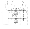
- the single figure shows schematically a schematic diagram of a arranged in a towing vehicle 13 trailer control unit 3, which is electrically connected via an unspecified connector with an adapter 1 according to the invention, which establishes an electrical connection 12 between the towing vehicle 13 and the trailer 14.
- the adapter 1 contains a circuit arrangement according to the invention. Of course, the circuit arrangement can also be arranged in the towing vehicle or in the trailer.
- the adapter 1 is arranged in an unspecified housing. At this is further connected via a further, also unspecified electrical connector a arranged in a trailer 14 trailer lamp 2 with a plurality of light emitting diode arrays 9 connected. For each light-emitting diode array 9, a separate control channel is provided. In the figure, only two channels are shown by way of example. Of course, the number of channels can be selected as needed.
- the voltage provided by the output terminal 11 is reduced to a suitable level for the light-emitting diode array 9.
- Downstream of the voltage divider 4 is an electrically coupled to a resistor 17 current mirror 5, which forms a current sensor 16 as a current measuring unit.
- the electrical resistor 17 is connected as a resistive element between the two emitters of the transistors of the current mirror 5.
- a trailer-side input terminal 15 is electrically connected in the trailer 14 with the light-emitting diode array 9. In circuit terms, the current through the light-emitting diode arrangement 9 hereby also flows through the resistor 17 of the current sensor 16.
- a light bulb simulation unit 18 is further connected, which has a switchable by means of a transistor 19 resistor 7, which is controllable via a further voltage divider from the current mirror 5.
- the resistor 7 could also be directly connected to the zugGerman spade terminal 11 of the adapter. Its value of electrical resistance would then be adjusted.
- the capacitor 6 causes a smoothing, so that the short switch-on pulse is reduced in terms of its electrical parameters to a degree, so that the light-emitting diode array 9 does not produce any visible lighting effect.
- the current is measured in front of the capacitor 6 with the current sensor 16 and the Light-bulb simulation unit 18 is driven accordingly, so that the monitoring device of the towing vehicle 13 can determine whether a proper function is given. In this way, the light-emitting diode array 9 can thus be checked even when switched off.
Landscapes
- Engineering & Computer Science (AREA)
- Mechanical Engineering (AREA)
- Circuit Arrangement For Electric Light Sources In General (AREA)
- Lighting Device Outwards From Vehicle And Optical Signal (AREA)
Priority Applications (1)
| Application Number | Priority Date | Filing Date | Title |
|---|---|---|---|
| PL08009912T PL2000359T3 (pl) | 2007-06-01 | 2008-05-30 | Układ połączeń |
Applications Claiming Priority (1)
| Application Number | Priority Date | Filing Date | Title |
|---|---|---|---|
| DE202007007777U DE202007007777U1 (de) | 2007-06-01 | 2007-06-01 | Schaltungsanordnung |
Publications (2)
| Publication Number | Publication Date |
|---|---|
| EP2000359A1 EP2000359A1 (de) | 2008-12-10 |
| EP2000359B1 true EP2000359B1 (de) | 2015-04-15 |
Family
ID=38375467
Family Applications (1)
| Application Number | Title | Priority Date | Filing Date |
|---|---|---|---|
| EP08009912.0A Not-in-force EP2000359B1 (de) | 2007-06-01 | 2008-05-30 | Schaltungsanordung |
Country Status (3)
| Country | Link |
|---|---|
| EP (1) | EP2000359B1 (pl) |
| DE (1) | DE202007007777U1 (pl) |
| PL (1) | PL2000359T3 (pl) |
Cited By (1)
| Publication number | Priority date | Publication date | Assignee | Title |
|---|---|---|---|---|
| DE102016221695A1 (de) | 2016-11-04 | 2018-05-09 | Audi Ag | Steuereinrichtung für ein Kraftfahrzeug, Kraftfahrzeug und Gespann |
Families Citing this family (11)
| Publication number | Priority date | Publication date | Assignee | Title |
|---|---|---|---|---|
| ES2375766T3 (es) * | 2008-07-22 | 2012-03-06 | Iveco Magirus Ag | Circuito para controlar la presencia de un remolque conectado a un camión de remolque, mediante el control del flujo de corriente eléctrica en las l�?mparas led traseras del remolque. |
| DE102008035885A1 (de) * | 2008-08-01 | 2010-02-04 | Aspöck Systems GmbH | Verfahren und Vorrichtung zur Erkennung eines Anhängers oder Auflegers an einem Kraftfahrzeug |
| DE102008042595B3 (de) † | 2008-10-02 | 2009-11-26 | Carsig GbR (Vertretungsberechtigter Gesellschafter: Herr Thomas Kliem, 78628 Rottweil) | Verfahren und Schaltung zur Überwachung von Fahrzeugbeleuchtung mit Glühlampensimulation |
| FR2939213B1 (fr) * | 2008-11-28 | 2011-04-15 | Valeo Vision Sas | Procede de controle d'un courant consomme par un element gere par un controleur principal d'un vehicule automobile et dispositif associe |
| DE102010002081A1 (de) * | 2010-02-18 | 2011-08-18 | Tridonic Ag | LED-Spannungsmessung |
| DE202010015919U1 (de) | 2010-11-26 | 2011-03-17 | Conwys Ag | Schaltungsanordnung für ein Fahrzeug |
| FR3011804B1 (fr) * | 2013-10-14 | 2017-05-12 | Norep Int | Feu de signalisation |
| SE539826C2 (sv) | 2014-10-29 | 2017-12-12 | Scania Cv Ab | Compensation unit configured to be connected between a control unit and at least one LED lamp |
| DE102016207825A1 (de) * | 2016-05-06 | 2017-11-09 | Osram Gmbh | Schaltungsanordnung und Verfahren zur Simulation eines Laststroms aus einem Bordnetz |
| DE102018005663A1 (de) * | 2018-07-18 | 2020-01-23 | Thomas Kliem | Glühlampensimulationsschaltung und Verfahren |
| CN110539711A (zh) * | 2019-09-09 | 2019-12-06 | 山东理工大学 | 一种拖挂式房车无线交互系统 |
Citations (2)
| Publication number | Priority date | Publication date | Assignee | Title |
|---|---|---|---|---|
| WO2004056608A1 (en) * | 2002-12-06 | 2004-07-08 | Ecs Electronics B.V. | Method and device for connecting a trailer lighting system to a vehicle lighting system |
| EP1653782A2 (de) * | 2004-05-04 | 2006-05-03 | ASPÖCK Systems GmbH | Led Kontrollgerät für Fahrzeugleuchten |
Family Cites Families (4)
| Publication number | Priority date | Publication date | Assignee | Title |
|---|---|---|---|---|
| GB2034948B (en) * | 1978-11-13 | 1983-01-06 | King G A | Monitoring circuits more particularly for monitoring lamp circuits |
| DE10215472B4 (de) | 2002-04-09 | 2007-08-02 | Hella Kgaa Hueck & Co. | Verfahren zum Betrieb einer Beleuchtungseinrichtung für Fahrzeuge mit einer mindestens eine Leuchtdiode aufweisenden Lampenanordnung sowie Beleuchtungseinrichtung für Fahrzeuge |
| DE10359196B4 (de) * | 2003-12-17 | 2016-12-15 | Hella Kgaa Hueck & Co. | Beleuchtungseinrichtung für ein Kraftfahrzeug |
| US20060028327A1 (en) * | 2004-08-09 | 2006-02-09 | Delbert Amis | Wireless replication, verification, and tracking apparatus and methods for towed vehicles |
-
2007
- 2007-06-01 DE DE202007007777U patent/DE202007007777U1/de not_active Expired - Lifetime
-
2008
- 2008-05-30 EP EP08009912.0A patent/EP2000359B1/de not_active Not-in-force
- 2008-05-30 PL PL08009912T patent/PL2000359T3/pl unknown
Patent Citations (2)
| Publication number | Priority date | Publication date | Assignee | Title |
|---|---|---|---|---|
| WO2004056608A1 (en) * | 2002-12-06 | 2004-07-08 | Ecs Electronics B.V. | Method and device for connecting a trailer lighting system to a vehicle lighting system |
| EP1653782A2 (de) * | 2004-05-04 | 2006-05-03 | ASPÖCK Systems GmbH | Led Kontrollgerät für Fahrzeugleuchten |
Cited By (2)
| Publication number | Priority date | Publication date | Assignee | Title |
|---|---|---|---|---|
| DE102016221695A1 (de) | 2016-11-04 | 2018-05-09 | Audi Ag | Steuereinrichtung für ein Kraftfahrzeug, Kraftfahrzeug und Gespann |
| DE102016221695B4 (de) | 2016-11-04 | 2024-08-01 | Audi Ag | Steuereinrichtung für ein Kraftfahrzeug, Kraftfahrzeug und Gespann |
Also Published As
| Publication number | Publication date |
|---|---|
| EP2000359A1 (de) | 2008-12-10 |
| DE202007007777U1 (de) | 2007-08-16 |
| PL2000359T3 (pl) | 2015-09-30 |
Similar Documents
| Publication | Publication Date | Title |
|---|---|---|
| EP2000359B1 (de) | Schaltungsanordung | |
| EP2000358B1 (de) | Schaltungsanordnung zur Versorgung von Leuchtdioden in einem Anhänger | |
| DE102004020691B4 (de) | Fahrzeugleuchte | |
| EP2377723B1 (de) | Anhängererkennungseinrichtung | |
| DE102007048378B3 (de) | Vorrichtung zum Anschluss an eine Anhängersteckdose eines Kraftfahrzeugs | |
| DE3724916A1 (de) | Kraftfahrzeug fuer anhaengerbetrieb mit heckleuchten-ueberwachung | |
| EP2287043B1 (de) | Fahrzeugbeleuchtungssystem mit Detektierung und Anzeige eines Ausfalls einer LED-Fahrzeugleuchte | |
| EP1653782B1 (de) | Led Kontrollgerät für Fahrzeugleuchten | |
| EP2633738B1 (de) | Verbund aus einem bordnetzsteuergerät und wenigstens einem lichtsteuergerät eines kraftfahrzeugs | |
| DE202007007776U1 (de) | Anhängeranschlußgerät | |
| EP1286567B1 (de) | Beleuchtungseinrichtung | |
| DE102015213291A1 (de) | Verfahren zum Betreiben einer ersten und einer zweiten Leuchteinheit eines Kraftfahrzeugs und Schaltungsanordnung | |
| DE202010005782U1 (de) | Fahrzeugleuchtenüberwachungseinrichtung | |
| DE102012102638A1 (de) | Fahrzeugbeleuchtungssysteme mit Detektierung einer Störung in einer der Fahrzeugleuchten | |
| DE202010015919U1 (de) | Schaltungsanordnung für ein Fahrzeug | |
| DE60302434T2 (de) | Erkennung von Anhängeranwesenheit und -typ durch Stromdetektion | |
| EP2080667A1 (de) | Verfahren zur Ausfallkontrolle von Lichtfunktionen in einem Kraftfahrzeugbordnetz | |
| EP3399840A1 (de) | Steuern von wenigstens einem leuchtmittel eines fahrzeugscheinwerfers abhängig von einer an einem fahrzeugscheinwerferanschluss eines fahrzeugs bereitstellbaren elektrischen grösse | |
| WO2022033744A1 (de) | Elektronische last zum verbauen in der leistungsversorgung einer fahrzeuglampe | |
| EP2648481B1 (de) | Adapter zum Anschluss von LED-Lampen an eine Spannungsversorgung mit Funktionsüberwachung für Glühlampen | |
| DE202007007775U1 (de) | Anhängeranschlußgerät | |
| DE202010016339U1 (de) | Schaltungsanordnung | |
| DE102022119081B4 (de) | Lichtsteuermodul zum ansteuern von led-modulen | |
| DE102014204386A1 (de) | Verfahren zur Steuerung einer Beleuchtungseinrichtung in einem Kraftfahrzeug | |
| DE102019101889A1 (de) | Verkabelung und Ansteuerungsmodul |
Legal Events
| Date | Code | Title | Description |
|---|---|---|---|
| PUAI | Public reference made under article 153(3) epc to a published international application that has entered the european phase |
Free format text: ORIGINAL CODE: 0009012 |
|
| AK | Designated contracting states |
Kind code of ref document: A1 Designated state(s): AT BE BG CH CY CZ DE DK EE ES FI FR GB GR HR HU IE IS IT LI LT LU LV MC MT NL NO PL PT RO SE SI SK TR |
|
| AX | Request for extension of the european patent |
Extension state: AL BA MK RS |
|
| 17P | Request for examination filed |
Effective date: 20090301 |
|
| AKX | Designation fees paid |
Designated state(s): AT BE BG CH CY CZ DE DK EE ES FI FR GB GR HR HU IE IS IT LI LT LU LV MC MT NL NO PL PT RO SE SI SK TR |
|
| 17Q | First examination report despatched |
Effective date: 20110824 |
|
| GRAP | Despatch of communication of intention to grant a patent |
Free format text: ORIGINAL CODE: EPIDOSNIGR1 |
|
| INTG | Intention to grant announced |
Effective date: 20150108 |
|
| RIN1 | Information on inventor provided before grant (corrected) |
Inventor name: WYSTRON, ALEXANDER |
|
| GRAS | Grant fee paid |
Free format text: ORIGINAL CODE: EPIDOSNIGR3 |
|
| GRAA | (expected) grant |
Free format text: ORIGINAL CODE: 0009210 |
|
| AK | Designated contracting states |
Kind code of ref document: B1 Designated state(s): AT BE BG CH CY CZ DE DK EE ES FI FR GB GR HR HU IE IS IT LI LT LU LV MC MT NL NO PL PT RO SE SI SK TR |
|
| REG | Reference to a national code |
Ref country code: GB Ref legal event code: FG4D Free format text: NOT ENGLISH Ref country code: CH Ref legal event code: EP |
|
| REG | Reference to a national code |
Ref country code: IE Ref legal event code: FG4D Free format text: LANGUAGE OF EP DOCUMENT: GERMAN |
|
| REG | Reference to a national code |
Ref country code: AT Ref legal event code: REF Ref document number: 721747 Country of ref document: AT Kind code of ref document: T Effective date: 20150515 |
|
| REG | Reference to a national code |
Ref country code: DE Ref legal event code: R096 Ref document number: 502008012877 Country of ref document: DE Effective date: 20150528 |
|
| REG | Reference to a national code |
Ref country code: SE Ref legal event code: TRGR |
|
| REG | Reference to a national code |
Ref country code: LT Ref legal event code: MG4D |
|
| REG | Reference to a national code |
Ref country code: PL Ref legal event code: T3 |
|
| PG25 | Lapsed in a contracting state [announced via postgrant information from national office to epo] |
Ref country code: FI Free format text: LAPSE BECAUSE OF FAILURE TO SUBMIT A TRANSLATION OF THE DESCRIPTION OR TO PAY THE FEE WITHIN THE PRESCRIBED TIME-LIMIT Effective date: 20150415 Ref country code: NO Free format text: LAPSE BECAUSE OF FAILURE TO SUBMIT A TRANSLATION OF THE DESCRIPTION OR TO PAY THE FEE WITHIN THE PRESCRIBED TIME-LIMIT Effective date: 20150715 Ref country code: ES Free format text: LAPSE BECAUSE OF FAILURE TO SUBMIT A TRANSLATION OF THE DESCRIPTION OR TO PAY THE FEE WITHIN THE PRESCRIBED TIME-LIMIT Effective date: 20150415 Ref country code: LT Free format text: LAPSE BECAUSE OF FAILURE TO SUBMIT A TRANSLATION OF THE DESCRIPTION OR TO PAY THE FEE WITHIN THE PRESCRIBED TIME-LIMIT Effective date: 20150415 Ref country code: HR Free format text: LAPSE BECAUSE OF FAILURE TO SUBMIT A TRANSLATION OF THE DESCRIPTION OR TO PAY THE FEE WITHIN THE PRESCRIBED TIME-LIMIT Effective date: 20150415 Ref country code: PT Free format text: LAPSE BECAUSE OF FAILURE TO SUBMIT A TRANSLATION OF THE DESCRIPTION OR TO PAY THE FEE WITHIN THE PRESCRIBED TIME-LIMIT Effective date: 20150817 |
|
| REG | Reference to a national code |
Ref country code: SK Ref legal event code: T3 Ref document number: E 19045 Country of ref document: SK |
|
| PG25 | Lapsed in a contracting state [announced via postgrant information from national office to epo] |
Ref country code: LV Free format text: LAPSE BECAUSE OF FAILURE TO SUBMIT A TRANSLATION OF THE DESCRIPTION OR TO PAY THE FEE WITHIN THE PRESCRIBED TIME-LIMIT Effective date: 20150415 Ref country code: GR Free format text: LAPSE BECAUSE OF FAILURE TO SUBMIT A TRANSLATION OF THE DESCRIPTION OR TO PAY THE FEE WITHIN THE PRESCRIBED TIME-LIMIT Effective date: 20150716 Ref country code: IS Free format text: LAPSE BECAUSE OF FAILURE TO SUBMIT A TRANSLATION OF THE DESCRIPTION OR TO PAY THE FEE WITHIN THE PRESCRIBED TIME-LIMIT Effective date: 20150815 |
|
| REG | Reference to a national code |
Ref country code: CH Ref legal event code: PL |
|
| REG | Reference to a national code |
Ref country code: DE Ref legal event code: R097 Ref document number: 502008012877 Country of ref document: DE |
|
| PG25 | Lapsed in a contracting state [announced via postgrant information from national office to epo] |
Ref country code: EE Free format text: LAPSE BECAUSE OF FAILURE TO SUBMIT A TRANSLATION OF THE DESCRIPTION OR TO PAY THE FEE WITHIN THE PRESCRIBED TIME-LIMIT Effective date: 20150415 Ref country code: MC Free format text: LAPSE BECAUSE OF FAILURE TO SUBMIT A TRANSLATION OF THE DESCRIPTION OR TO PAY THE FEE WITHIN THE PRESCRIBED TIME-LIMIT Effective date: 20150415 Ref country code: CH Free format text: LAPSE BECAUSE OF NON-PAYMENT OF DUE FEES Effective date: 20150531 Ref country code: DK Free format text: LAPSE BECAUSE OF FAILURE TO SUBMIT A TRANSLATION OF THE DESCRIPTION OR TO PAY THE FEE WITHIN THE PRESCRIBED TIME-LIMIT Effective date: 20150415 Ref country code: LI Free format text: LAPSE BECAUSE OF NON-PAYMENT OF DUE FEES Effective date: 20150531 Ref country code: IT Free format text: LAPSE BECAUSE OF FAILURE TO SUBMIT A TRANSLATION OF THE DESCRIPTION OR TO PAY THE FEE WITHIN THE PRESCRIBED TIME-LIMIT Effective date: 20150415 |
|
| PLBE | No opposition filed within time limit |
Free format text: ORIGINAL CODE: 0009261 |
|
| STAA | Information on the status of an ep patent application or granted ep patent |
Free format text: STATUS: NO OPPOSITION FILED WITHIN TIME LIMIT |
|
| REG | Reference to a national code |
Ref country code: IE Ref legal event code: MM4A |
|
| REG | Reference to a national code |
Ref country code: FR Ref legal event code: ST Effective date: 20160129 |
|
| PG25 | Lapsed in a contracting state [announced via postgrant information from national office to epo] |
Ref country code: RO Free format text: LAPSE BECAUSE OF NON-PAYMENT OF DUE FEES Effective date: 20150415 |
|
| 26N | No opposition filed |
Effective date: 20160118 |
|
| PG25 | Lapsed in a contracting state [announced via postgrant information from national office to epo] |
Ref country code: IE Free format text: LAPSE BECAUSE OF NON-PAYMENT OF DUE FEES Effective date: 20150530 |
|
| PG25 | Lapsed in a contracting state [announced via postgrant information from national office to epo] |
Ref country code: SI Free format text: LAPSE BECAUSE OF FAILURE TO SUBMIT A TRANSLATION OF THE DESCRIPTION OR TO PAY THE FEE WITHIN THE PRESCRIBED TIME-LIMIT Effective date: 20150415 Ref country code: FR Free format text: LAPSE BECAUSE OF NON-PAYMENT OF DUE FEES Effective date: 20150615 |
|
| REG | Reference to a national code |
Ref country code: AT Ref legal event code: MM01 Ref document number: 721747 Country of ref document: AT Kind code of ref document: T Effective date: 20150530 |
|
| PG25 | Lapsed in a contracting state [announced via postgrant information from national office to epo] |
Ref country code: AT Free format text: LAPSE BECAUSE OF NON-PAYMENT OF DUE FEES Effective date: 20150530 |
|
| PG25 | Lapsed in a contracting state [announced via postgrant information from national office to epo] |
Ref country code: MT Free format text: LAPSE BECAUSE OF FAILURE TO SUBMIT A TRANSLATION OF THE DESCRIPTION OR TO PAY THE FEE WITHIN THE PRESCRIBED TIME-LIMIT Effective date: 20150415 |
|
| PG25 | Lapsed in a contracting state [announced via postgrant information from national office to epo] |
Ref country code: BG Free format text: LAPSE BECAUSE OF FAILURE TO SUBMIT A TRANSLATION OF THE DESCRIPTION OR TO PAY THE FEE WITHIN THE PRESCRIBED TIME-LIMIT Effective date: 20150415 Ref country code: HU Free format text: LAPSE BECAUSE OF FAILURE TO SUBMIT A TRANSLATION OF THE DESCRIPTION OR TO PAY THE FEE WITHIN THE PRESCRIBED TIME-LIMIT; INVALID AB INITIO Effective date: 20080530 |
|
| PG25 | Lapsed in a contracting state [announced via postgrant information from national office to epo] |
Ref country code: CY Free format text: LAPSE BECAUSE OF FAILURE TO SUBMIT A TRANSLATION OF THE DESCRIPTION OR TO PAY THE FEE WITHIN THE PRESCRIBED TIME-LIMIT Effective date: 20150415 |
|
| PG25 | Lapsed in a contracting state [announced via postgrant information from national office to epo] |
Ref country code: BE Free format text: LAPSE BECAUSE OF NON-PAYMENT OF DUE FEES Effective date: 20150531 |
|
| PG25 | Lapsed in a contracting state [announced via postgrant information from national office to epo] |
Ref country code: TR Free format text: LAPSE BECAUSE OF FAILURE TO SUBMIT A TRANSLATION OF THE DESCRIPTION OR TO PAY THE FEE WITHIN THE PRESCRIBED TIME-LIMIT Effective date: 20150415 |
|
| PG25 | Lapsed in a contracting state [announced via postgrant information from national office to epo] |
Ref country code: LU Free format text: LAPSE BECAUSE OF NON-PAYMENT OF DUE FEES Effective date: 20150530 |
|
| REG | Reference to a national code |
Ref country code: DE Ref legal event code: R082 Ref document number: 502008012877 Country of ref document: DE Representative=s name: RAUSCH WANISCHECK-BERGMANN BRINKMANN PARTNERSC, DE |
|
| PGFP | Annual fee paid to national office [announced via postgrant information from national office to epo] |
Ref country code: SK Payment date: 20180529 Year of fee payment: 11 Ref country code: CZ Payment date: 20180529 Year of fee payment: 11 |
|
| PGFP | Annual fee paid to national office [announced via postgrant information from national office to epo] |
Ref country code: PL Payment date: 20180419 Year of fee payment: 11 Ref country code: NL Payment date: 20180518 Year of fee payment: 11 |
|
| PGFP | Annual fee paid to national office [announced via postgrant information from national office to epo] |
Ref country code: SE Payment date: 20180518 Year of fee payment: 11 |
|
| PGFP | Annual fee paid to national office [announced via postgrant information from national office to epo] |
Ref country code: DE Payment date: 20180727 Year of fee payment: 11 Ref country code: GB Payment date: 20180518 Year of fee payment: 11 |
|
| REG | Reference to a national code |
Ref country code: DE Ref legal event code: R119 Ref document number: 502008012877 Country of ref document: DE |
|
| REG | Reference to a national code |
Ref country code: NL Ref legal event code: MM Effective date: 20190601 |
|
| GBPC | Gb: european patent ceased through non-payment of renewal fee |
Effective date: 20190530 |
|
| PG25 | Lapsed in a contracting state [announced via postgrant information from national office to epo] |
Ref country code: CZ Free format text: LAPSE BECAUSE OF NON-PAYMENT OF DUE FEES Effective date: 20190530 Ref country code: SE Free format text: LAPSE BECAUSE OF NON-PAYMENT OF DUE FEES Effective date: 20190531 Ref country code: SK Free format text: LAPSE BECAUSE OF NON-PAYMENT OF DUE FEES Effective date: 20190530 |
|
| REG | Reference to a national code |
Ref country code: SK Ref legal event code: MM4A Ref document number: E 19045 Country of ref document: SK Effective date: 20190530 |
|
| PG25 | Lapsed in a contracting state [announced via postgrant information from national office to epo] |
Ref country code: NL Free format text: LAPSE BECAUSE OF NON-PAYMENT OF DUE FEES Effective date: 20190601 Ref country code: DE Free format text: LAPSE BECAUSE OF NON-PAYMENT OF DUE FEES Effective date: 20191203 Ref country code: GB Free format text: LAPSE BECAUSE OF NON-PAYMENT OF DUE FEES Effective date: 20190530 |
|
| REG | Reference to a national code |
Ref country code: SE Ref legal event code: EUG |
|
| PG25 | Lapsed in a contracting state [announced via postgrant information from national office to epo] |
Ref country code: PL Free format text: LAPSE BECAUSE OF NON-PAYMENT OF DUE FEES Effective date: 20190530 |