EP2000348B1 - Schienenfahrzeug und Bahnsteiganschluss für dieses Fahrzeug - Google Patents
Schienenfahrzeug und Bahnsteiganschluss für dieses Fahrzeug Download PDFInfo
- Publication number
- EP2000348B1 EP2000348B1 EP08103519A EP08103519A EP2000348B1 EP 2000348 B1 EP2000348 B1 EP 2000348B1 EP 08103519 A EP08103519 A EP 08103519A EP 08103519 A EP08103519 A EP 08103519A EP 2000348 B1 EP2000348 B1 EP 2000348B1
- Authority
- EP
- European Patent Office
- Prior art keywords
- auxiliary
- ground
- impedance
- conductor
- circuit
- Prior art date
- Legal status (The legal status is an assumption and is not a legal conclusion. Google has not performed a legal analysis and makes no representation as to the accuracy of the status listed.)
- Active
Links
Images
Classifications
-
- B—PERFORMING OPERATIONS; TRANSPORTING
- B60—VEHICLES IN GENERAL
- B60L—PROPULSION OF ELECTRICALLY-PROPELLED VEHICLES; SUPPLYING ELECTRIC POWER FOR AUXILIARY EQUIPMENT OF ELECTRICALLY-PROPELLED VEHICLES; ELECTRODYNAMIC BRAKE SYSTEMS FOR VEHICLES IN GENERAL; MAGNETIC SUSPENSION OR LEVITATION FOR VEHICLES; MONITORING OPERATING VARIABLES OF ELECTRICALLY-PROPELLED VEHICLES; ELECTRIC SAFETY DEVICES FOR ELECTRICALLY-PROPELLED VEHICLES
- B60L1/00—Supplying electric power to auxiliary equipment of vehicles
- B60L1/02—Supplying electric power to auxiliary equipment of vehicles to electric heating circuits
- B60L1/04—Supplying electric power to auxiliary equipment of vehicles to electric heating circuits fed by the power supply line
- B60L1/10—Supplying electric power to auxiliary equipment of vehicles to electric heating circuits fed by the power supply line with provision for using different supplies
-
- H—ELECTRICITY
- H02—GENERATION; CONVERSION OR DISTRIBUTION OF ELECTRIC POWER
- H02M—APPARATUS FOR CONVERSION BETWEEN AC AND AC, BETWEEN AC AND DC, OR BETWEEN DC AND DC, AND FOR USE WITH MAINS OR SIMILAR POWER SUPPLY SYSTEMS; CONVERSION OF DC OR AC INPUT POWER INTO SURGE OUTPUT POWER; CONTROL OR REGULATION THEREOF
- H02M1/00—Details of apparatus for conversion
- H02M1/12—Arrangements for reducing harmonics from AC input or output
- H02M1/126—Arrangements for reducing harmonics from AC input or output using passive filters
-
- B—PERFORMING OPERATIONS; TRANSPORTING
- B60—VEHICLES IN GENERAL
- B60L—PROPULSION OF ELECTRICALLY-PROPELLED VEHICLES; SUPPLYING ELECTRIC POWER FOR AUXILIARY EQUIPMENT OF ELECTRICALLY-PROPELLED VEHICLES; ELECTRODYNAMIC BRAKE SYSTEMS FOR VEHICLES IN GENERAL; MAGNETIC SUSPENSION OR LEVITATION FOR VEHICLES; MONITORING OPERATING VARIABLES OF ELECTRICALLY-PROPELLED VEHICLES; ELECTRIC SAFETY DEVICES FOR ELECTRICALLY-PROPELLED VEHICLES
- B60L2200/00—Type of vehicles
- B60L2200/26—Rail vehicles
Definitions
- the present invention relates to a railway vehicle and a workshop equipped with a docking point for this vehicle.
- medium voltage here is meant an alternating voltage of between 100 and 1000 Vac and a frequency of less than or equal to 60 Hz, typically 400 Vrms 50 Hz three-phase.
- catenary we designate as well catenaries suspended above the railways as a catenary placed on the ground and to feed the railway vehicle.
- the catenary on the ground is better known as the "third rail”.
- auxiliary charges consist of all the electrical equipment on board the railway vehicle and which must be supplied with electricity with the exception of the propulsion engines of the vehicle.
- auxiliary loads can be air conditioners, fans, lighting or a battery charger.
- Directly means that the electrical connection is made without passing through an electrical conductor or an electrical component whose impedance at frequencies greater than 10 kHz is greater than the impedance of the EMC filter at the same respective frequencies.
- the auxiliary converter when the auxiliary converter operates to supply the auxiliary bus at medium voltage, it generates high frequency spurious electrical signals.
- high frequency is meant a signal whose frequency is greater than or equal to 10 kHz.
- the impedance of the capacitors C1 is very low. Consequently, the EMC filter makes it possible to short-circuit the high frequency spurious signals. With this, the electromagnetic disturbances conducted and radiated by the converter and the rail vehicle are sufficiently reduced to meet the standards in the field, such as for example, the standard EN 50 121-3-2.
- the existing rail vehicles are equipped with the shore power supply which can be connected to a medium voltage network connected to the platform.
- the medium voltage network typically comprises three phase conductors and a neutral conductor permanently connected to the ground.
- the platform is also equipped with a differential circuit breaker interposed between the shore power supply and the medium voltage network so as to electrically isolate this shore power plug from the medium voltage network in the event of an insulation fault between the phase (s) and the earth. .
- the medium voltage network produces a leakage current to earth, that is to say that the sum of currents currents currents in the three phase conductors is not equal to the return current returning to the neutral conductor.
- the GFCI can trip even if no dangerous insulation fault for the safety of persons or equipment exists in the railway vehicle.
- the stray capacitances of the electrical equipment and, in particular, the EMC filter create a current leakage path at the fundamental frequency of the network between the phase conductors of the auxiliary bus and the earth. Then, this leakage current joins the neutral conductor of the medium voltage three-phase network via the earth ground of this network.
- the leakage current follows this path, it does not go back through the differential circuit breaker. Therefore, as soon as the intensity of the leakage current exceeds the tripping threshold of the circuit breaker, typically 100 mA, it may cause inadvertent tripping of the power supply of the dock.
- the invention aims to remedy the aforementioned drawback without using a galvanic isolation between the auxiliary bus and the medium voltage network.
- the auxiliary converter when the auxiliary converter operates to supply the auxiliary bus, it generates high frequency spurious electrical signals. At high frequencies, like capacitance C1, the impedance of the electrical isolation circuit is very low. Consequently, the high frequency signals are short-circuited to ground, which limits the electromagnetic disturbances conducted and radiated by the converters and the railway vehicle sufficiently to meet the electromagnetic compatibility standards.
- This workshop also comprises the above railway vehicle in which the socket which is secured to the railway vehicle is plug-in into the wharf connected to the dock so as to supply the auxiliary bus from the medium voltage network.
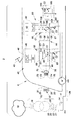
- the figure represents a workshop 2 equipped with dock 4 and a railway vehicle 6 docked at platform 4.
- the vehicle 6 is, for example, a train or a subway.
- the network 10 is, for example, made using a three-phase transformer 16 connected to the primary to an electricity distribution network 18 and the secondary to a medium voltage bus 20.
- the bus 20 is formed of three phase conductors 21 to 23 and a conductor 24 of neutral.
- the conductor 24 is permanently connected to the ground.
- the circuit breaker 14 is connected between, on one side the conductors 21 to 24, and on the other side to a wire link 26 at the end of which is the socket 12.
- the link 26 comprises four electrical conductors electrically connected to a respective conductor bus 20 through the circuit breaker 14. To simplify the figure, the four conductors of the link 26 have not been shown.
- the circuit breaker 14 is designed to break automatically as soon as the sum of the intensities of the currents flowing at a given moment in the different conductors of the link 26 is, in absolute value, greater than a predetermined threshold S d .
- the threshold S d is generally strictly greater than 100 mA and, for example, here equal to 300 mA.
- the socket 12 has four sockets 30 to 33 electrically connected to a respective conductor of the link 26.
- the vehicle 6 is equipped with a pantograph 40 clean rub on a catenary to capture electrical energy from it when the vehicle rolls.
- the catenary can be supplied with 25 kVac at 50 Hz, at 15 kVac at 16 Hz 2/3 or at a DC voltage of 1500 or 3000 VDC.
- the catenary is connected via various equipment not shown to an auxiliary supply box 42 for supplying an auxiliary bus 44 at three-phase medium voltage.
- the envelope 46 is typically a conductive envelope, for example of metal, connected to ground.
- the connection of the various equipment embedded inside the vehicle 6 to the ground is done, for example, by means of the wheels of the vehicle 6 and the rails on which the vehicle 6 rolls.
- the converter 48 is connected to a DC bus (not shown) embedded inside the vehicle 6.
- the DC bus is formed of two DC voltage supplied conductors via the pantograph 40.
- the converter 48 is here an inverter three-phase circuit capable of generating a three-phase medium voltage of 400 Vac at 50 Hz from the DC voltage of the DC bus.
- the switches 50 make it possible to electrically isolate the converter 48 from the bus 44 when the supply by the catenary is interrupted or in the event of a fault of the converter.
- the bus 44 has three phase conductors 55 to 57 and a neutral conductor 58.
- the converter 48 is connected to each of the conductors 55 to 58, via the switches 50, at connection points 60 to 63.
- the filter 52 is directly connected between the connection points 60 to 62 and the converter ground.
- the mass of the converter is connected to the ground through the wheels of the railway vehicle and its structure or cable.
- the filter 52 is able to short-circuit the high frequency spurious signals generated by the converter 48 to ground.
- the filter 52 comprises three capacitors C1 directly connected between one of the respective connection points 60 to 62 and a common point 64.
- the impedance of the conductor 66 at 50 Hz is here lower than the impedance of the electrical isolation circuit at the same frequency in a ratio of at least one tenth.
- the capacitances of the capacitors C1 and of the capacitor C2 are here taken equal.
- the capacity of the capacitor C2 is chosen between 1 nF and 1 mF.
- capacitance of capacitor C2 is chosen equal to 1 ⁇ F.
- the capacitances of the capacitors C1 and C2 are chosen so as to comply with the standards EN 50 121-3-2 for the complete train and EN 50 121-3-1 for the devices constituting it.
- the limit is defined by the same EN 50 121-3-1 for the train and complete vehicles supplied by the pantograph 40 or the plug 12.
- emission driving the limit is defined by the standard EN 50 121-3 -2 for single devices.
- the vehicle also comprises a plug 70 dock integral with the casing 46.
- This socket 70 comprises four pins 72 to 75 electrically and directly connected, respectively, to the conductors 55 to 58 via an isolation contactor 76 without going through the intermediate of a transformer or a galvanically isolated converter.
- the sockets 30 to 32 are able to receive the pins 72 to 75 so as to supply the bus 44 from the network 10.
- the vehicle 6 also includes many auxiliary loads. Some have their own electrical converter so as to convert the three-phase voltage to another voltage or frequency necessary for their operation.
- auxiliary load 80 is, for example, an air conditioner.
- the load 80 comprises a compressor 82 supplied with alternating current of variable frequency by means of a three-phase-three-phase converter 84 connected to the phase conductors 55 to 58.
- the converter 84 is connected to each of these conductors 55 to 58 by intermediate of respective connection points 86 to 89.
- the load 80 also includes its own EMC filter 90.
- This filter 90 is directly connected between the points 86 to 88 and the mass of the load.
- the mass of the load is connected to the ground through the wheels of the railway vehicle and its structure or cable.
- the structure of the filter 90 is identical to that of the filter 52 and will not be described here in more detail.
- the capacitances of the capacitors C1 and C2 which form the filter 90 are determined in the same way as that described with respect to the filter 52. For example, its capacities are identical to those of the filter 52.
- the resistor 104 has a value significantly greater than that of the current return conductor to the medium voltage network of the shore power supply but is significantly lower than the resistor 106.
- the capacitance of the capacitor C3 is chosen so as to constitute a short circuit between the conductor 58 and the ground for the high frequencies.
- the 50 Hz impedance of the capacitor C3 is greater than or equal to the resistor 106.
- the capacitance of the capacitor C3 is chosen to be equal to that of the capacitor C2.
- the on-board circuit breaker is normally closed. If following an insulation fault between a phase and ground, a fault current, greater than the detection threshold set by the control circuit 108, is detected by the circuit breaker, the opening of the circuit breaker 102 signals the defect of isolation to maintenance personnel, while maintaining power to the auxiliary bus.
- the capacitor C3 and the resistor 106 ensure that in case of opening of the circuit breaker 102 the potential of the neutral conductor (58) will remain close to that of the ground.
- the network 10 is a three-phase network producing a leakage current. Under these conditions, a leakage current passes through at least one of the capacitors C1 to reach the common point 64. At this point, the leakage current returns to the conductor 58 via the conductor 66. Indeed, the conductor 66 has an impedance at 50 Hz significantly smaller than the impedance of the capacitors C2 of the different equipment of the train and that of the resistors 104, 106 and the capacitor C3 of the detection circuit 100. Thus, the leakage current returns to the network 10 via the conductor 58, the wired link 26 before reaching the conductor 24. Under these conditions, although the network 10 is unbalanced, the sum of the current intensities in the different phase conductors and in the conductor Neutral remains below the differential detection threshold, here 300 mA so that the circuit breaker 14 does not trip.
- the differential detection threshold here 300 mA
- the filter 90 prevents inadvertent tripping of the circuit breaker 14.
- the circuit 100 isolates the conductor 58 from the ground so that the leakage current can not leak through this circuit either.
- the socket 12 is withdrawn from the socket 70, the isolation switch 76 is open and the vehicle 6 is fed again via the pantograph 40 and a catenary .
- the switches 50 connect the converter 48 to the bus 44. From this moment, the bus 44 is supplied with medium voltage via the converter 48 and no longer via the jack 70. operating mode, the filters 52 and 90 reduce the effect of the signals high frequency electric motors so as to reduce conducted and radiated disturbances due to switching of the switches of the various converters on board the vehicle 6.
- auxiliary power converter of the bus or the converter of an auxiliary load is either located in the locomotive of the vehicle 6 or in a passenger car.
- the converter 84 and the filter 90 can be integrated inside the case 42.
- the plug 70 can be omitted if, for example, the three-phase voltage supply source of the auxiliary bus is embedded in the vehicle 6, a plug-free electrical connection means providing the connection between the voltage supply source embedded in the vehicle. vehicle 6 and the three-phase auxiliary bus (44).
Landscapes
- Engineering & Computer Science (AREA)
- Power Engineering (AREA)
- Transportation (AREA)
- Mechanical Engineering (AREA)
- Electric Propulsion And Braking For Vehicles (AREA)
- Train Traffic Observation, Control, And Security (AREA)
- Vehicle Waterproofing, Decoration, And Sanitation Devices (AREA)
Claims (6)
- Schienenfahrzeug, das Folgendes aufweiset:- einen Hilfsbus (44) zur Versorgung mit Mittelspannung, der von mindestens einem Phasenleiter (55-57) und mindestens einem Nullleiter (58) gebildet wird, an die Hilfslasten (80) angeschlossen sind, die sich im Inneren des Schienenfahrzeugs befinden,- mindestens einen Hilfswandler (48), der ausgehend von einer Fahrleitung aufgefangene elektrische Energie in Mittelspannung umwandeln kann, die an den Hilfsbus (44) geliefert wird, wenn das Schienenfahrzeug mit der Fahrleitung verbunden ist, wobei dieser Hilfswandler zu diesem Zweck an die Phasen- und Nullleiter des Hilfsbusses an Anschlusspunkten (60-63) angeschlossen und mit einer geerdeten Wandlermasse versehen ist,- ein erstes EMK-Filter (elektromagnetische Kompatibilität) (52), das direkt zwischen den Anschlusspunkten der Phasenleiter und der Masse des Hilfswandlers angeschlossen ist, wobei dieses EMK-Filter einen Kondensator C1 aufweist, der zwischen jedem Phasenanschlusspunkt des Hilfswandlers und einem gleichen gemeinsamen Punkt (64) angeschlossen ist, der an die Masse des wandlers angeschlossen ist, wobei "direkt" bedeutet, dass der Anschluss erfolgt, ohne über einen elektrischen Leiter oder ein elektrisches Bauteil zu gehen, dessen. Impedanz bei den Frequenzen höher als 10 kHz höher als die Impedanz von C1 bei den gleichen jeweiligen Frequenzen ist, und- eine fest mit dem Schienenfahrzeug verbundene und an jeden Leiter (55-58) des Hilfsbusses (44) angeschlossene Verbindungseinrichtung (70), die eine Versorgung des Hilfsbusses mit Mittelspannung elektrisch verbinden kann, wenn das Schienenfahrzeug von der Fahrleitung angeklemmt ist,dadurch gekennzeichnet, dass das EMK-Filter Folgendes aufweist:- e.ine elektrische Isolierschaltung (C2), die direkt zwischen dem gemeinsamen Punkt (64) und der Masse des Wandlers angeschlossen ist, deren Impedanz bei 50 Hz zwischen dem gemeinsamen Punkt und der Masse des Wandlers mindestens doppelt so hoch wie die Impedanz des Nullleiterbereichs ist, der zwischen dem EMK-Filter und der Verbindungseinrichtung (70) liegt, und deren Impedanz bei den Frequenzen höher als 10 kHz zwischen dem gemeinsamen Punkt und der Masse geringer als oder in der gleichen Größenordnung ist wie die Impedanz von C1 bei den gleichen jeweiligen Frequenzen, und- einen elektrischen Kurzschlussleiter (66), der zwei Ende hat, von denen eines direkt an den gemeinsamen Punkt (64) und das andere direkt an den Nullleiter angeschlossen ist, wobei die Impedanz bei 50 Hz zwischen den zwei Enden dieses Leiters geringer als die Hälfte der Impedanz von C2 bei der gleichen Frequenz ist.
- Fahrzeug nach Anspruch 1, bei dem die elektrische Isolierschaltung von einem Kondensator C2 gebildet wird, der ständig zwischen dem gemeinsamen Punkt (64) und der Erde angeschlossen ist, wobei die Kapazität dieses Kondensator C2 zwischen 1 nF und 1 mF liegt.
- Fahrzeug nach einem der vorhergehenden Ansprüche, bei dem mindestens eine Hilfslast (80), die an den Hilfsbus über jeweilige Anschlusspunkte (86-89) abgeschlossen und mit einer geerdeten Hilfslastmasse versehen ist, mit ihrem eigenen zweiten EMK-Filter (90) ausgestattet ist, das direkt zwischen den Phasenanschlusspunkten (86-88) und der Masse der mindestens einen Hilfslast angeschlossen ist, wobei dieses EMK-Filter Folgendes aufweist:- einen Kondensator C1, der zwischen jedem Phasenanschlusspunkt (86-88) der mindestens einen Hilfslast und einem gleichen gemeinsamen Punkt angeschlossen ist, der an die Masse der mindestens einen Hilfslast angeschlossen ist, wobei "direkt" bedeutet, dass der Anschluss erfolgt, ohne über einen elektrischen Leiter order ein elektrische Bauteil zu gehen, dessen Impedanz bei den Frequenzen höher als 10 kHz höher als die Impedanz von C1 bei den gleichen jeweilige Frequenzen ist,- eine elektrische Isolierschaltung (C2), die direkt zwischen dem gemeinsamen Punkt und der Masse der mindestens einen Hilfslast angeschlossen ist, deren Impedanz bei 50 Hz zwischen dem gemeinsamen Punkt und der Masse der Hilfslast mindestens doppelt so hoch wie die Impedanz des Nullleiterbereichs ist, der zwischen dem EMK-Filter und der Verbindungseinrichtung (70) liegt, und deren Impedanz bei den Frequenzen höher als 10 kHz zwischen dem gemeinsamen Punkt und der Masse geringer als oder in der gleichen Größenordnung ist wie die Impedanz von C1 bei den gleichen jeweiligen Frequenzen, und- einen elektrischen Kurzschlussleiter, der zwei Enden hat, von denen eines direkt an den gemeinsamen Punkt und das andere direkt an den Nullleiter angeschlossen ist, wobei die Impedanz bei 50 Hz zwischen den zwei Enden dieses Leiters geringer als die Hälfte der Impedanz von C2 bei der gleichen Frequenz ist.
- Fahrzeug nach einem der vorhergehenden Ansprüche, bei dem das Fahrzeug eine Schaltung (100), die mit einer Masse der geerdeten Schaltung versehen ist, zum Anlegen an Masse des Nullleiters (58) und zur Erfassung eines Isolierfehlers zwischen einem Phasenleiter und der Masse der Schaltung aufweiset, wobei die Schaltung (100) zwischen dem Nullleiter (58) und der Masse der Schaltung in Reihe geschaltet einen an Bord befindlichen Erfassungs-Schutzschalter (102) und einen Widerstand (104) enthält, wobei die Schaltung (100) ebenfalls eine Fehler-Erdungsimpedanz (C3, 106) enthält, die zwischen dem Nullleiter (58) und der Masse der Schaltung angeschlossen ist.
- Fahrzeug nach einem der vorhergehenden Ansprüche, bei dem das Fahrzeug einen Hilfsversorgungskasten (42) aufweist, der mit einer geerdeten Auskleidung (45) ausgestattet ist, in deren Innerem der Hilfswandler und das erste EMK-Filter untergebracht sind, wobei der Kasten (42) die Masse des Hilfswandlers bildet.
- Werkstatt, die Folgendes enthält:- ein gemäß Anspruch 1 definiertes Schienenfahrzeug (6),- ein Mittelspannungsnetz (10), das mehrere elektrische Leiter (20-24) aufweist, darunter mindestens einen Phasenleiter und einen elektrisch geerdeten Nullleiter (24),- einen fest mit dem Bahnsteig verbundenen Bahnsteiganschluss (12), wobei dieser Anschluss über verschiedene Leiter (26) an das Mittelspannungsnetz angeschlossen ist,- einen Fehlerstromschutzschalter (14), der zwischen das Mittelspannunganetz (10) und den fest mit dem Bahnsteig verbundenen Bahnsteiganschluss (12) eingefügt ist, wobei dieser Schutzschalter (14) automatisch von eine leitenden Zustand in einen nicht leitenden Zustand kippen kann, sobald der Absolutwert der Summe der in den verschiedenen Leitern des Mittelapannungsnetzes fließenden Stromstärken höher als oder gleich 100 mA ist, undbei dem die fest mit dem Schienenfahrzeug verbundene Bahnsteig-Verbindungseinrichtung (70) in den fest mit dem Bahnsteig verbundenen Bahnsteiganschluss (12) eingesteckt werden kann, um den Hilfsbus (44) ausgehend vom Mittelspannungsnetz zu versorgen.
Applications Claiming Priority (1)
| Application Number | Priority Date | Filing Date | Title |
|---|---|---|---|
| FR0755607A FR2917017B1 (fr) | 2007-06-08 | 2007-06-08 | Vehicule ferroviaire et atelier equipe d'une prise de quai pour ce vehicule |
Publications (2)
| Publication Number | Publication Date |
|---|---|
| EP2000348A1 EP2000348A1 (de) | 2008-12-10 |
| EP2000348B1 true EP2000348B1 (de) | 2011-09-21 |
Family
ID=38921739
Family Applications (1)
| Application Number | Title | Priority Date | Filing Date |
|---|---|---|---|
| EP08103519A Active EP2000348B1 (de) | 2007-06-08 | 2008-04-14 | Schienenfahrzeug und Bahnsteiganschluss für dieses Fahrzeug |
Country Status (4)
| Country | Link |
|---|---|
| EP (1) | EP2000348B1 (de) |
| AT (1) | ATE525237T1 (de) |
| ES (1) | ES2369435T3 (de) |
| FR (1) | FR2917017B1 (de) |
Families Citing this family (2)
| Publication number | Priority date | Publication date | Assignee | Title |
|---|---|---|---|---|
| CN106505722B (zh) * | 2016-11-29 | 2020-12-25 | 中车长春轨道客车股份有限公司 | 一种动车组外接中压供电系统 |
| FR3128910A1 (fr) * | 2021-11-08 | 2023-05-12 | Speedinnov | Véhicule ferroviaire comportant un dispositif de mise à la terre |
Family Cites Families (2)
| Publication number | Priority date | Publication date | Assignee | Title |
|---|---|---|---|---|
| WO2006130735A2 (en) * | 2005-06-01 | 2006-12-07 | Leviton Manufacturing Co., Inc. | Circuit interrupting device having integrated enhanced rfi suppression |
| DE202006018439U1 (de) * | 2006-12-04 | 2007-02-15 | Hanning Elektro-Werke Gmbh & Co. Kg | Vorrichtung zur Verringerung von Erdableitströmen |
-
2007
- 2007-06-08 FR FR0755607A patent/FR2917017B1/fr not_active Expired - Fee Related
-
2008
- 2008-04-14 ES ES08103519T patent/ES2369435T3/es active Active
- 2008-04-14 EP EP08103519A patent/EP2000348B1/de active Active
- 2008-04-14 AT AT08103519T patent/ATE525237T1/de active
Also Published As
| Publication number | Publication date |
|---|---|
| FR2917017A1 (fr) | 2008-12-12 |
| FR2917017B1 (fr) | 2009-10-16 |
| ES2369435T3 (es) | 2011-11-30 |
| ATE525237T1 (de) | 2011-10-15 |
| EP2000348A1 (de) | 2008-12-10 |
Similar Documents
| Publication | Publication Date | Title |
|---|---|---|
| JP5835634B2 (ja) | 接地と関連するサージ電圧に対する光電発生器の光起電モジュールの保護 | |
| CN102474172B (zh) | 电压中间电路变换器的中间电路电容器的放电方法 | |
| EP2352661B1 (de) | Verbindungsgehäuse für ein kraftfahrzeug | |
| KR102827475B1 (ko) | 전기 직류 계통 보호 장치, 차량용 온보드 전기 시스템, 차량 및 직류 충전 스테이션 | |
| FR2986671A1 (fr) | Procede et dispositif de decharge du circuit intermediaire d'un reseau de tension | |
| US20230061714A1 (en) | Electric vehicle charging arrangement and method for charging an electric vehicle | |
| FR2970784A1 (fr) | Dispositif de detection de defaut de connexion a la terre d'un systeme a connecteur electrique | |
| EP2677645B1 (de) | Ladungseinspeisungssystem, das einen mit einem Netz verbundenen Stromrichter umfasst sowie einen parallel zum Stromrichter geschalteten Transformator, um den Nullstrom zu begrenzen, und Antriebskette, die ein solches System umfasst | |
| DE102010063126A1 (de) | Ladevorrichtung für Kraftfahrzeuge und Ladeverfahren | |
| EP2000348B1 (de) | Schienenfahrzeug und Bahnsteiganschluss für dieses Fahrzeug | |
| EP1902894B1 (de) | Mit Schaltern ausgestattetes Schienenfahrzeug; Verfahren zur Steuerung und zur Verwendung dieser Schalter | |
| FR3013848A1 (fr) | Dispositif et procede d'echange securitaire d'energie electrique entre un consommateur et une source d'energie electrique | |
| CN215867050U (zh) | 接地检测电路、三相三线制交流供电系统及地铁车辆 | |
| JP2024528862A (ja) | 自動車の車載電気システムおよび方法 | |
| CN110661331A (zh) | 一种交直变换器 | |
| US20010003500A1 (en) | Electrical protection relay | |
| EP3082241B1 (de) | Batterieladegerät, elektrische anlage und kraftfahrzeug | |
| EP3545589B1 (de) | Sicheres elektrisches anschluss-system | |
| WO2016097581A1 (fr) | Dispositif de filtrage de mode commun | |
| EP2999084B1 (de) | Elektrische verbindungsvorrichtung für stromquellen-umschalter, und stromquellen-umschalter, der eine solche vorrichtung umfasst | |
| CN112953255B (zh) | 一种牵引变流器 | |
| JPS5911701A (ja) | 客車補助電源用自動電力供給システム | |
| FR3044177A1 (fr) | Chargeur de batterie embarque dans un vehicule automobile muni d'au moins un moteur electrique | |
| JP2025145573A (ja) | 漏電検出回路 | |
| CN113525131A (zh) | 一种分体八枪电动汽车直流充电桩及过欠压保护系统 |
Legal Events
| Date | Code | Title | Description |
|---|---|---|---|
| PUAI | Public reference made under article 153(3) epc to a published international application that has entered the european phase |
Free format text: ORIGINAL CODE: 0009012 |
|
| AK | Designated contracting states |
Kind code of ref document: A1 Designated state(s): AT BE BG CH CY CZ DE DK EE ES FI FR GB GR HR HU IE IS IT LI LT LU LV MC MT NL NO PL PT RO SE SI SK TR |
|
| AX | Request for extension of the european patent |
Extension state: AL BA MK RS |
|
| 17P | Request for examination filed |
Effective date: 20081217 |
|
| AKX | Designation fees paid |
Designated state(s): AT BE BG CH CY CZ DE DK EE ES FI FR GB GR HR HU IE IS IT LI LT LU LV MC MT NL NO PL PT RO SE SI SK TR |
|
| GRAP | Despatch of communication of intention to grant a patent |
Free format text: ORIGINAL CODE: EPIDOSNIGR1 |
|
| GRAS | Grant fee paid |
Free format text: ORIGINAL CODE: EPIDOSNIGR3 |
|
| GRAA | (expected) grant |
Free format text: ORIGINAL CODE: 0009210 |
|
| AK | Designated contracting states |
Kind code of ref document: B1 Designated state(s): AT BE BG CH CY CZ DE DK EE ES FI FR GB GR HR HU IE IS IT LI LT LU LV MC MT NL NO PL PT RO SE SI SK TR |
|
| REG | Reference to a national code |
Ref country code: GB Ref legal event code: FG4D Free format text: NOT ENGLISH |
|
| REG | Reference to a national code |
Ref country code: CH Ref legal event code: EP |
|
| REG | Reference to a national code |
Ref country code: IE Ref legal event code: FG4D Free format text: LANGUAGE OF EP DOCUMENT: FRENCH |
|
| REG | Reference to a national code |
Ref country code: DE Ref legal event code: R096 Ref document number: 602008009933 Country of ref document: DE Effective date: 20111117 |
|
| REG | Reference to a national code |
Ref country code: ES Ref legal event code: FG2A Ref document number: 2369435 Country of ref document: ES Kind code of ref document: T3 Effective date: 20111130 Ref country code: NL Ref legal event code: T3 |
|
| REG | Reference to a national code |
Ref country code: SE Ref legal event code: TRGR |
|
| PG25 | Lapsed in a contracting state [announced via postgrant information from national office to epo] |
Ref country code: NO Free format text: LAPSE BECAUSE OF FAILURE TO SUBMIT A TRANSLATION OF THE DESCRIPTION OR TO PAY THE FEE WITHIN THE PRESCRIBED TIME-LIMIT Effective date: 20111221 Ref country code: HR Free format text: LAPSE BECAUSE OF FAILURE TO SUBMIT A TRANSLATION OF THE DESCRIPTION OR TO PAY THE FEE WITHIN THE PRESCRIBED TIME-LIMIT Effective date: 20110921 Ref country code: LT Free format text: LAPSE BECAUSE OF FAILURE TO SUBMIT A TRANSLATION OF THE DESCRIPTION OR TO PAY THE FEE WITHIN THE PRESCRIBED TIME-LIMIT Effective date: 20110921 Ref country code: FI Free format text: LAPSE BECAUSE OF FAILURE TO SUBMIT A TRANSLATION OF THE DESCRIPTION OR TO PAY THE FEE WITHIN THE PRESCRIBED TIME-LIMIT Effective date: 20110921 |
|
| LTIE | Lt: invalidation of european patent or patent extension |
Effective date: 20110921 |
|
| PG25 | Lapsed in a contracting state [announced via postgrant information from national office to epo] |
Ref country code: LV Free format text: LAPSE BECAUSE OF FAILURE TO SUBMIT A TRANSLATION OF THE DESCRIPTION OR TO PAY THE FEE WITHIN THE PRESCRIBED TIME-LIMIT Effective date: 20110921 Ref country code: CY Free format text: LAPSE BECAUSE OF FAILURE TO SUBMIT A TRANSLATION OF THE DESCRIPTION OR TO PAY THE FEE WITHIN THE PRESCRIBED TIME-LIMIT Effective date: 20110921 Ref country code: SI Free format text: LAPSE BECAUSE OF FAILURE TO SUBMIT A TRANSLATION OF THE DESCRIPTION OR TO PAY THE FEE WITHIN THE PRESCRIBED TIME-LIMIT Effective date: 20110921 Ref country code: GR Free format text: LAPSE BECAUSE OF FAILURE TO SUBMIT A TRANSLATION OF THE DESCRIPTION OR TO PAY THE FEE WITHIN THE PRESCRIBED TIME-LIMIT Effective date: 20111222 |
|
| REG | Reference to a national code |
Ref country code: IE Ref legal event code: FD4D |
|
| PG25 | Lapsed in a contracting state [announced via postgrant information from national office to epo] |
Ref country code: SK Free format text: LAPSE BECAUSE OF FAILURE TO SUBMIT A TRANSLATION OF THE DESCRIPTION OR TO PAY THE FEE WITHIN THE PRESCRIBED TIME-LIMIT Effective date: 20110921 Ref country code: IE Free format text: LAPSE BECAUSE OF FAILURE TO SUBMIT A TRANSLATION OF THE DESCRIPTION OR TO PAY THE FEE WITHIN THE PRESCRIBED TIME-LIMIT Effective date: 20110921 Ref country code: CZ Free format text: LAPSE BECAUSE OF FAILURE TO SUBMIT A TRANSLATION OF THE DESCRIPTION OR TO PAY THE FEE WITHIN THE PRESCRIBED TIME-LIMIT Effective date: 20110921 Ref country code: IS Free format text: LAPSE BECAUSE OF FAILURE TO SUBMIT A TRANSLATION OF THE DESCRIPTION OR TO PAY THE FEE WITHIN THE PRESCRIBED TIME-LIMIT Effective date: 20120121 |
|
| PG25 | Lapsed in a contracting state [announced via postgrant information from national office to epo] |
Ref country code: EE Free format text: LAPSE BECAUSE OF FAILURE TO SUBMIT A TRANSLATION OF THE DESCRIPTION OR TO PAY THE FEE WITHIN THE PRESCRIBED TIME-LIMIT Effective date: 20110921 Ref country code: PT Free format text: LAPSE BECAUSE OF FAILURE TO SUBMIT A TRANSLATION OF THE DESCRIPTION OR TO PAY THE FEE WITHIN THE PRESCRIBED TIME-LIMIT Effective date: 20120123 Ref country code: RO Free format text: LAPSE BECAUSE OF FAILURE TO SUBMIT A TRANSLATION OF THE DESCRIPTION OR TO PAY THE FEE WITHIN THE PRESCRIBED TIME-LIMIT Effective date: 20110921 Ref country code: PL Free format text: LAPSE BECAUSE OF FAILURE TO SUBMIT A TRANSLATION OF THE DESCRIPTION OR TO PAY THE FEE WITHIN THE PRESCRIBED TIME-LIMIT Effective date: 20110921 |
|
| PLBE | No opposition filed within time limit |
Free format text: ORIGINAL CODE: 0009261 |
|
| STAA | Information on the status of an ep patent application or granted ep patent |
Free format text: STATUS: NO OPPOSITION FILED WITHIN TIME LIMIT |
|
| PG25 | Lapsed in a contracting state [announced via postgrant information from national office to epo] |
Ref country code: DK Free format text: LAPSE BECAUSE OF FAILURE TO SUBMIT A TRANSLATION OF THE DESCRIPTION OR TO PAY THE FEE WITHIN THE PRESCRIBED TIME-LIMIT Effective date: 20110921 |
|
| 26N | No opposition filed |
Effective date: 20120622 |
|
| REG | Reference to a national code |
Ref country code: DE Ref legal event code: R097 Ref document number: 602008009933 Country of ref document: DE Effective date: 20120622 |
|
| PG25 | Lapsed in a contracting state [announced via postgrant information from national office to epo] |
Ref country code: MC Free format text: LAPSE BECAUSE OF NON-PAYMENT OF DUE FEES Effective date: 20120430 |
|
| PG25 | Lapsed in a contracting state [announced via postgrant information from national office to epo] |
Ref country code: BG Free format text: LAPSE BECAUSE OF FAILURE TO SUBMIT A TRANSLATION OF THE DESCRIPTION OR TO PAY THE FEE WITHIN THE PRESCRIBED TIME-LIMIT Effective date: 20111221 |
|
| PG25 | Lapsed in a contracting state [announced via postgrant information from national office to epo] |
Ref country code: MT Free format text: LAPSE BECAUSE OF FAILURE TO SUBMIT A TRANSLATION OF THE DESCRIPTION OR TO PAY THE FEE WITHIN THE PRESCRIBED TIME-LIMIT Effective date: 20110921 |
|
| PG25 | Lapsed in a contracting state [announced via postgrant information from national office to epo] |
Ref country code: TR Free format text: LAPSE BECAUSE OF FAILURE TO SUBMIT A TRANSLATION OF THE DESCRIPTION OR TO PAY THE FEE WITHIN THE PRESCRIBED TIME-LIMIT Effective date: 20110921 |
|
| PG25 | Lapsed in a contracting state [announced via postgrant information from national office to epo] |
Ref country code: LU Free format text: LAPSE BECAUSE OF NON-PAYMENT OF DUE FEES Effective date: 20120414 |
|
| PG25 | Lapsed in a contracting state [announced via postgrant information from national office to epo] |
Ref country code: HU Free format text: LAPSE BECAUSE OF FAILURE TO SUBMIT A TRANSLATION OF THE DESCRIPTION OR TO PAY THE FEE WITHIN THE PRESCRIBED TIME-LIMIT Effective date: 20080414 |
|
| REG | Reference to a national code |
Ref country code: FR Ref legal event code: TP Owner name: ALSTOM TRANSPORT TECHNOLOGIES, FR Effective date: 20141209 |
|
| REG | Reference to a national code |
Ref country code: CH Ref legal event code: PUE Owner name: ALSTOM TRANSPORT TECHNOLOGIES, FR Free format text: FORMER OWNER: ALSTOM TRANSPORT SA, FR |
|
| REG | Reference to a national code |
Ref country code: DE Ref legal event code: R081 Ref document number: 602008009933 Country of ref document: DE Owner name: ALSTOM TRANSPORT TECHNOLOGIES, FR Free format text: FORMER OWNER: ALSTOM TRANSPORT SA, LEVALLOIS-PERRET, FR |
|
| REG | Reference to a national code |
Ref country code: GB Ref legal event code: 732E Free format text: REGISTERED BETWEEN 20151119 AND 20151125 |
|
| REG | Reference to a national code |
Ref country code: NL Ref legal event code: PD Owner name: ALSTOM TRANSPORT TECHNOLOGIES; FR Free format text: DETAILS ASSIGNMENT: VERANDERING VAN EIGENAAR(S), OVERDRACHT; FORMER OWNER NAME: ALSTOM TRANSPORT SA Effective date: 20150904 |
|
| REG | Reference to a national code |
Ref country code: FR Ref legal event code: PLFP Year of fee payment: 9 |
|
| REG | Reference to a national code |
Ref country code: FR Ref legal event code: PLFP Year of fee payment: 10 |
|
| REG | Reference to a national code |
Ref country code: DE Ref legal event code: R081 Ref document number: 602008009933 Country of ref document: DE Owner name: ALSTOM TRANSPORT TECHNOLOGIES, FR Free format text: FORMER OWNER: ALSTOM TRANSPORT TECHNOLOGIES, LEVALLOIS-PERRET, FR |
|
| REG | Reference to a national code |
Ref country code: CH Ref legal event code: NV Representative=s name: BUGNION S.A., CH Ref country code: CH Ref legal event code: PCOW Free format text: NEW ADDRESS: 48 RUE ALBERT DHALENNE, 93400 SAINT-OUEN (FR) |
|
| REG | Reference to a national code |
Ref country code: FR Ref legal event code: CA Effective date: 20180103 |
|
| REG | Reference to a national code |
Ref country code: AT Ref legal event code: PC Ref document number: 525237 Country of ref document: AT Kind code of ref document: T Owner name: ALSTOM TRANSPORT TECHNOLOGIES, FR Effective date: 20180220 |
|
| REG | Reference to a national code |
Ref country code: FR Ref legal event code: PLFP Year of fee payment: 11 |
|
| PGFP | Annual fee paid to national office [announced via postgrant information from national office to epo] |
Ref country code: SE Payment date: 20210420 Year of fee payment: 14 Ref country code: AT Payment date: 20210421 Year of fee payment: 14 Ref country code: BE Payment date: 20210420 Year of fee payment: 14 Ref country code: GB Payment date: 20210421 Year of fee payment: 14 Ref country code: ES Payment date: 20210621 Year of fee payment: 14 Ref country code: CH Payment date: 20210420 Year of fee payment: 14 |
|
| PGFP | Annual fee paid to national office [announced via postgrant information from national office to epo] |
Ref country code: NL Payment date: 20210420 Year of fee payment: 14 |
|
| REG | Reference to a national code |
Ref country code: SE Ref legal event code: EUG |
|
| REG | Reference to a national code |
Ref country code: CH Ref legal event code: PL |
|
| REG | Reference to a national code |
Ref country code: NL Ref legal event code: MM Effective date: 20220501 |
|
| REG | Reference to a national code |
Ref country code: AT Ref legal event code: MM01 Ref document number: 525237 Country of ref document: AT Kind code of ref document: T Effective date: 20220414 |
|
| GBPC | Gb: european patent ceased through non-payment of renewal fee |
Effective date: 20220414 |
|
| REG | Reference to a national code |
Ref country code: BE Ref legal event code: MM Effective date: 20220430 |
|
| PG25 | Lapsed in a contracting state [announced via postgrant information from national office to epo] |
Ref country code: SE Free format text: LAPSE BECAUSE OF NON-PAYMENT OF DUE FEES Effective date: 20220415 Ref country code: NL Free format text: LAPSE BECAUSE OF NON-PAYMENT OF DUE FEES Effective date: 20220501 Ref country code: LI Free format text: LAPSE BECAUSE OF NON-PAYMENT OF DUE FEES Effective date: 20220430 Ref country code: GB Free format text: LAPSE BECAUSE OF NON-PAYMENT OF DUE FEES Effective date: 20220414 Ref country code: CH Free format text: LAPSE BECAUSE OF NON-PAYMENT OF DUE FEES Effective date: 20220430 Ref country code: AT Free format text: LAPSE BECAUSE OF NON-PAYMENT OF DUE FEES Effective date: 20220414 |
|
| PG25 | Lapsed in a contracting state [announced via postgrant information from national office to epo] |
Ref country code: BE Free format text: LAPSE BECAUSE OF NON-PAYMENT OF DUE FEES Effective date: 20220430 |
|
| REG | Reference to a national code |
Ref country code: ES Ref legal event code: FD2A Effective date: 20230529 |
|
| PG25 | Lapsed in a contracting state [announced via postgrant information from national office to epo] |
Ref country code: ES Free format text: LAPSE BECAUSE OF NON-PAYMENT OF DUE FEES Effective date: 20220415 |
|
| P01 | Opt-out of the competence of the unified patent court (upc) registered |
Effective date: 20231025 |
|
| PGFP | Annual fee paid to national office [announced via postgrant information from national office to epo] |
Ref country code: DE Payment date: 20250422 Year of fee payment: 18 |
|
| PGFP | Annual fee paid to national office [announced via postgrant information from national office to epo] |
Ref country code: IT Payment date: 20250424 Year of fee payment: 18 |
|
| PGFP | Annual fee paid to national office [announced via postgrant information from national office to epo] |
Ref country code: FR Payment date: 20250424 Year of fee payment: 18 |