EP2000348B1 - Railway vehicle and workshop equipped with a platform socket for this vehicle - Google Patents
Railway vehicle and workshop equipped with a platform socket for this vehicle Download PDFInfo
- Publication number
- EP2000348B1 EP2000348B1 EP08103519A EP08103519A EP2000348B1 EP 2000348 B1 EP2000348 B1 EP 2000348B1 EP 08103519 A EP08103519 A EP 08103519A EP 08103519 A EP08103519 A EP 08103519A EP 2000348 B1 EP2000348 B1 EP 2000348B1
- Authority
- EP
- European Patent Office
- Prior art keywords
- auxiliary
- ground
- impedance
- conductor
- circuit
- Prior art date
- Legal status (The legal status is an assumption and is not a legal conclusion. Google has not performed a legal analysis and makes no representation as to the accuracy of the status listed.)
- Active
Links
Images
Classifications
-
- B—PERFORMING OPERATIONS; TRANSPORTING
- B60—VEHICLES IN GENERAL
- B60L—PROPULSION OF ELECTRICALLY-PROPELLED VEHICLES; SUPPLYING ELECTRIC POWER FOR AUXILIARY EQUIPMENT OF ELECTRICALLY-PROPELLED VEHICLES; ELECTRODYNAMIC BRAKE SYSTEMS FOR VEHICLES IN GENERAL; MAGNETIC SUSPENSION OR LEVITATION FOR VEHICLES; MONITORING OPERATING VARIABLES OF ELECTRICALLY-PROPELLED VEHICLES; ELECTRIC SAFETY DEVICES FOR ELECTRICALLY-PROPELLED VEHICLES
- B60L1/00—Supplying electric power to auxiliary equipment of vehicles
- B60L1/02—Supplying electric power to auxiliary equipment of vehicles to electric heating circuits
- B60L1/04—Supplying electric power to auxiliary equipment of vehicles to electric heating circuits fed by the power supply line
- B60L1/10—Supplying electric power to auxiliary equipment of vehicles to electric heating circuits fed by the power supply line with provision for using different supplies
-
- H—ELECTRICITY
- H02—GENERATION; CONVERSION OR DISTRIBUTION OF ELECTRIC POWER
- H02M—APPARATUS FOR CONVERSION BETWEEN AC AND AC, BETWEEN AC AND DC, OR BETWEEN DC AND DC, AND FOR USE WITH MAINS OR SIMILAR POWER SUPPLY SYSTEMS; CONVERSION OF DC OR AC INPUT POWER INTO SURGE OUTPUT POWER; CONTROL OR REGULATION THEREOF
- H02M1/00—Details of apparatus for conversion
- H02M1/12—Arrangements for reducing harmonics from AC input or output
- H02M1/126—Arrangements for reducing harmonics from AC input or output using passive filters
-
- B—PERFORMING OPERATIONS; TRANSPORTING
- B60—VEHICLES IN GENERAL
- B60L—PROPULSION OF ELECTRICALLY-PROPELLED VEHICLES; SUPPLYING ELECTRIC POWER FOR AUXILIARY EQUIPMENT OF ELECTRICALLY-PROPELLED VEHICLES; ELECTRODYNAMIC BRAKE SYSTEMS FOR VEHICLES IN GENERAL; MAGNETIC SUSPENSION OR LEVITATION FOR VEHICLES; MONITORING OPERATING VARIABLES OF ELECTRICALLY-PROPELLED VEHICLES; ELECTRIC SAFETY DEVICES FOR ELECTRICALLY-PROPELLED VEHICLES
- B60L2200/00—Type of vehicles
- B60L2200/26—Rail vehicles
Definitions
- the present invention relates to a railway vehicle and a workshop equipped with a docking point for this vehicle.
- medium voltage here is meant an alternating voltage of between 100 and 1000 Vac and a frequency of less than or equal to 60 Hz, typically 400 Vrms 50 Hz three-phase.
- catenary we designate as well catenaries suspended above the railways as a catenary placed on the ground and to feed the railway vehicle.
- the catenary on the ground is better known as the "third rail”.
- auxiliary charges consist of all the electrical equipment on board the railway vehicle and which must be supplied with electricity with the exception of the propulsion engines of the vehicle.
- auxiliary loads can be air conditioners, fans, lighting or a battery charger.
- Directly means that the electrical connection is made without passing through an electrical conductor or an electrical component whose impedance at frequencies greater than 10 kHz is greater than the impedance of the EMC filter at the same respective frequencies.
- the auxiliary converter when the auxiliary converter operates to supply the auxiliary bus at medium voltage, it generates high frequency spurious electrical signals.
- high frequency is meant a signal whose frequency is greater than or equal to 10 kHz.
- the impedance of the capacitors C1 is very low. Consequently, the EMC filter makes it possible to short-circuit the high frequency spurious signals. With this, the electromagnetic disturbances conducted and radiated by the converter and the rail vehicle are sufficiently reduced to meet the standards in the field, such as for example, the standard EN 50 121-3-2.
- the existing rail vehicles are equipped with the shore power supply which can be connected to a medium voltage network connected to the platform.
- the medium voltage network typically comprises three phase conductors and a neutral conductor permanently connected to the ground.
- the platform is also equipped with a differential circuit breaker interposed between the shore power supply and the medium voltage network so as to electrically isolate this shore power plug from the medium voltage network in the event of an insulation fault between the phase (s) and the earth. .
- the medium voltage network produces a leakage current to earth, that is to say that the sum of currents currents currents in the three phase conductors is not equal to the return current returning to the neutral conductor.
- the GFCI can trip even if no dangerous insulation fault for the safety of persons or equipment exists in the railway vehicle.
- the stray capacitances of the electrical equipment and, in particular, the EMC filter create a current leakage path at the fundamental frequency of the network between the phase conductors of the auxiliary bus and the earth. Then, this leakage current joins the neutral conductor of the medium voltage three-phase network via the earth ground of this network.
- the leakage current follows this path, it does not go back through the differential circuit breaker. Therefore, as soon as the intensity of the leakage current exceeds the tripping threshold of the circuit breaker, typically 100 mA, it may cause inadvertent tripping of the power supply of the dock.
- the invention aims to remedy the aforementioned drawback without using a galvanic isolation between the auxiliary bus and the medium voltage network.
- the auxiliary converter when the auxiliary converter operates to supply the auxiliary bus, it generates high frequency spurious electrical signals. At high frequencies, like capacitance C1, the impedance of the electrical isolation circuit is very low. Consequently, the high frequency signals are short-circuited to ground, which limits the electromagnetic disturbances conducted and radiated by the converters and the railway vehicle sufficiently to meet the electromagnetic compatibility standards.
- This workshop also comprises the above railway vehicle in which the socket which is secured to the railway vehicle is plug-in into the wharf connected to the dock so as to supply the auxiliary bus from the medium voltage network.
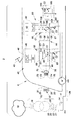
- the figure represents a workshop 2 equipped with dock 4 and a railway vehicle 6 docked at platform 4.
- the vehicle 6 is, for example, a train or a subway.
- the network 10 is, for example, made using a three-phase transformer 16 connected to the primary to an electricity distribution network 18 and the secondary to a medium voltage bus 20.
- the bus 20 is formed of three phase conductors 21 to 23 and a conductor 24 of neutral.
- the conductor 24 is permanently connected to the ground.
- the circuit breaker 14 is connected between, on one side the conductors 21 to 24, and on the other side to a wire link 26 at the end of which is the socket 12.
- the link 26 comprises four electrical conductors electrically connected to a respective conductor bus 20 through the circuit breaker 14. To simplify the figure, the four conductors of the link 26 have not been shown.
- the circuit breaker 14 is designed to break automatically as soon as the sum of the intensities of the currents flowing at a given moment in the different conductors of the link 26 is, in absolute value, greater than a predetermined threshold S d .
- the threshold S d is generally strictly greater than 100 mA and, for example, here equal to 300 mA.
- the socket 12 has four sockets 30 to 33 electrically connected to a respective conductor of the link 26.
- the vehicle 6 is equipped with a pantograph 40 clean rub on a catenary to capture electrical energy from it when the vehicle rolls.
- the catenary can be supplied with 25 kVac at 50 Hz, at 15 kVac at 16 Hz 2/3 or at a DC voltage of 1500 or 3000 VDC.
- the catenary is connected via various equipment not shown to an auxiliary supply box 42 for supplying an auxiliary bus 44 at three-phase medium voltage.
- the envelope 46 is typically a conductive envelope, for example of metal, connected to ground.
- the connection of the various equipment embedded inside the vehicle 6 to the ground is done, for example, by means of the wheels of the vehicle 6 and the rails on which the vehicle 6 rolls.
- the converter 48 is connected to a DC bus (not shown) embedded inside the vehicle 6.
- the DC bus is formed of two DC voltage supplied conductors via the pantograph 40.
- the converter 48 is here an inverter three-phase circuit capable of generating a three-phase medium voltage of 400 Vac at 50 Hz from the DC voltage of the DC bus.
- the switches 50 make it possible to electrically isolate the converter 48 from the bus 44 when the supply by the catenary is interrupted or in the event of a fault of the converter.
- the bus 44 has three phase conductors 55 to 57 and a neutral conductor 58.
- the converter 48 is connected to each of the conductors 55 to 58, via the switches 50, at connection points 60 to 63.
- the filter 52 is directly connected between the connection points 60 to 62 and the converter ground.
- the mass of the converter is connected to the ground through the wheels of the railway vehicle and its structure or cable.
- the filter 52 is able to short-circuit the high frequency spurious signals generated by the converter 48 to ground.
- the filter 52 comprises three capacitors C1 directly connected between one of the respective connection points 60 to 62 and a common point 64.
- the impedance of the conductor 66 at 50 Hz is here lower than the impedance of the electrical isolation circuit at the same frequency in a ratio of at least one tenth.
- the capacitances of the capacitors C1 and of the capacitor C2 are here taken equal.
- the capacity of the capacitor C2 is chosen between 1 nF and 1 mF.
- capacitance of capacitor C2 is chosen equal to 1 ⁇ F.
- the capacitances of the capacitors C1 and C2 are chosen so as to comply with the standards EN 50 121-3-2 for the complete train and EN 50 121-3-1 for the devices constituting it.
- the limit is defined by the same EN 50 121-3-1 for the train and complete vehicles supplied by the pantograph 40 or the plug 12.
- emission driving the limit is defined by the standard EN 50 121-3 -2 for single devices.
- the vehicle also comprises a plug 70 dock integral with the casing 46.
- This socket 70 comprises four pins 72 to 75 electrically and directly connected, respectively, to the conductors 55 to 58 via an isolation contactor 76 without going through the intermediate of a transformer or a galvanically isolated converter.
- the sockets 30 to 32 are able to receive the pins 72 to 75 so as to supply the bus 44 from the network 10.
- the vehicle 6 also includes many auxiliary loads. Some have their own electrical converter so as to convert the three-phase voltage to another voltage or frequency necessary for their operation.
- auxiliary load 80 is, for example, an air conditioner.
- the load 80 comprises a compressor 82 supplied with alternating current of variable frequency by means of a three-phase-three-phase converter 84 connected to the phase conductors 55 to 58.
- the converter 84 is connected to each of these conductors 55 to 58 by intermediate of respective connection points 86 to 89.
- the load 80 also includes its own EMC filter 90.
- This filter 90 is directly connected between the points 86 to 88 and the mass of the load.
- the mass of the load is connected to the ground through the wheels of the railway vehicle and its structure or cable.
- the structure of the filter 90 is identical to that of the filter 52 and will not be described here in more detail.
- the capacitances of the capacitors C1 and C2 which form the filter 90 are determined in the same way as that described with respect to the filter 52. For example, its capacities are identical to those of the filter 52.
- the resistor 104 has a value significantly greater than that of the current return conductor to the medium voltage network of the shore power supply but is significantly lower than the resistor 106.
- the capacitance of the capacitor C3 is chosen so as to constitute a short circuit between the conductor 58 and the ground for the high frequencies.
- the 50 Hz impedance of the capacitor C3 is greater than or equal to the resistor 106.
- the capacitance of the capacitor C3 is chosen to be equal to that of the capacitor C2.
- the on-board circuit breaker is normally closed. If following an insulation fault between a phase and ground, a fault current, greater than the detection threshold set by the control circuit 108, is detected by the circuit breaker, the opening of the circuit breaker 102 signals the defect of isolation to maintenance personnel, while maintaining power to the auxiliary bus.
- the capacitor C3 and the resistor 106 ensure that in case of opening of the circuit breaker 102 the potential of the neutral conductor (58) will remain close to that of the ground.
- the network 10 is a three-phase network producing a leakage current. Under these conditions, a leakage current passes through at least one of the capacitors C1 to reach the common point 64. At this point, the leakage current returns to the conductor 58 via the conductor 66. Indeed, the conductor 66 has an impedance at 50 Hz significantly smaller than the impedance of the capacitors C2 of the different equipment of the train and that of the resistors 104, 106 and the capacitor C3 of the detection circuit 100. Thus, the leakage current returns to the network 10 via the conductor 58, the wired link 26 before reaching the conductor 24. Under these conditions, although the network 10 is unbalanced, the sum of the current intensities in the different phase conductors and in the conductor Neutral remains below the differential detection threshold, here 300 mA so that the circuit breaker 14 does not trip.
- the differential detection threshold here 300 mA
- the filter 90 prevents inadvertent tripping of the circuit breaker 14.
- the circuit 100 isolates the conductor 58 from the ground so that the leakage current can not leak through this circuit either.
- the socket 12 is withdrawn from the socket 70, the isolation switch 76 is open and the vehicle 6 is fed again via the pantograph 40 and a catenary .
- the switches 50 connect the converter 48 to the bus 44. From this moment, the bus 44 is supplied with medium voltage via the converter 48 and no longer via the jack 70. operating mode, the filters 52 and 90 reduce the effect of the signals high frequency electric motors so as to reduce conducted and radiated disturbances due to switching of the switches of the various converters on board the vehicle 6.
- auxiliary power converter of the bus or the converter of an auxiliary load is either located in the locomotive of the vehicle 6 or in a passenger car.
- the converter 84 and the filter 90 can be integrated inside the case 42.
- the plug 70 can be omitted if, for example, the three-phase voltage supply source of the auxiliary bus is embedded in the vehicle 6, a plug-free electrical connection means providing the connection between the voltage supply source embedded in the vehicle. vehicle 6 and the three-phase auxiliary bus (44).
Landscapes
- Engineering & Computer Science (AREA)
- Power Engineering (AREA)
- Transportation (AREA)
- Mechanical Engineering (AREA)
- Electric Propulsion And Braking For Vehicles (AREA)
- Vehicle Waterproofing, Decoration, And Sanitation Devices (AREA)
- Train Traffic Observation, Control, And Security (AREA)
Abstract
Description
La présente invention concerne un véhicule ferroviaire et un atelier équipé d'une prise de quai pour ce véhicule.The present invention relates to a railway vehicle and a workshop equipped with a docking point for this vehicle.
Il existe des véhicules ferroviaires comportant :
- un bus auxiliaire d'alimentation en moyenne tension formé d'au moins un conducteur de phase et d'un conducteur de neutre, auxquels sont raccordées des charges auxiliaires embarquées à l'intérieur du véhicule ferroviaire,
- au moins un convertisseur auxiliaire apte à convertir de l'énergie électrique captée à partir d'une caténaire en de la moyenne tension délivrée sur le bus auxiliaire lorsque le véhicule ferroviaire est connecté à la caténaire, ce convertisseur auxiliaire étant raccordé à cet effet aux conducteurs de phase et de neutre du bus auxiliaire en des points de raccordement, et muni d'une masse de convertisseur raccordée à la terre,
- un premier filtre CEM (Compatibilité Electromagnétique) directement raccordé entre les points de raccordement aux conducteurs de phase et la masse, comportant un condensateur C1 raccordé entre chaque point de raccordement du convertisseur auxiliaire et un même point commun raccordé à la masse, et
- une prise de quai solidaire du véhicule ferroviaire et raccordée à chaque conducteur du bus auxiliaire, cette prise étant apte, lorsque le véhicule ferroviaire est à quai, à être embrochée avec une prise correspondante solidaire du quai pour alimenter le bus auxiliaire en moyenne tension à partir de la prise de quai lorsque le véhicule ferroviaire est déconnecté de la caténaire et, en alternance, à être débrochée de la prise de quai correspondante lorsque le véhicule ferroviaire roule.
- a medium-voltage auxiliary supply bus formed of at least one phase conductor and a neutral conductor, to which auxiliary charges embedded in the railway vehicle are connected,
- at least one auxiliary converter capable of converting electrical energy picked up from a catenary into the medium voltage delivered on the auxiliary bus when the railway vehicle is connected to the catenary, this auxiliary converter being connected for this purpose to the drivers phase and neutral of the auxiliary bus at connection points, and provided with a grounded converter ground,
- a first EMC (Electromagnetic Compatibility) filter directly connected between the connection points to the phase conductors and the ground, comprising a capacitor C1 connected between each connection point of the auxiliary converter and the same common point connected to ground, and
- a dock plug integral with the railway vehicle and connected to each driver of the auxiliary bus, this plug being adapted, when the railway vehicle is docked, to be plugged with a corresponding socket integral with the platform to supply the auxiliary bus at medium voltage from of the shore power station when the rail vehicle is disconnected from the catenary and, alternately, to be removed from the corresponding shore power when the railway vehicle is running.
Un tel véhicule est décrit par exemple dans le document:
Par moyenne tension, on désigne ici une tension alternative comprise entre 100 et 1000 Vca et de fréquence inférieure ou égale à 60 Hz, typiquement 400 Veff 50Hz triphasé.By medium voltage, here is meant an alternating voltage of between 100 and 1000 Vac and a frequency of less than or equal to 60 Hz, typically 400
Par caténaire, on désigne aussi bien des caténaires suspendues au-dessus des voies ferrées qu'une caténaire posée au sol et permettant d'alimenter le véhicule ferroviaire. La caténaire posée au sol est plus connue sous le terme de « troisième rail ».By catenary, we designate as well catenaries suspended above the railways as a catenary placed on the ground and to feed the railway vehicle. The catenary on the ground is better known as the "third rail".
Les charges auxiliaires sont constituées de tous les équipements électriques embarqués dans le véhicule ferroviaire et qui doivent être alimentés en électricité à l'exception des moteurs de propulsion du véhicule. Par exemple, les charges auxiliaires peuvent être des climatiseurs, des ventilateurs, l'éclairage ou encore un chargeur de batterie.Auxiliary charges consist of all the electrical equipment on board the railway vehicle and which must be supplied with electricity with the exception of the propulsion engines of the vehicle. For example, auxiliary loads can be air conditioners, fans, lighting or a battery charger.
On désigne par « directement » le fait que le raccordement électrique est réalisé sans passer par l'intermédiaire d'un conducteur électrique ou d'un composant électrique dont l'impédance aux fréquences supérieures à 10 kHz est supérieure à l'impédance du filtre CEM aux mêmes fréquences respectives."Directly" means that the electrical connection is made without passing through an electrical conductor or an electrical component whose impedance at frequencies greater than 10 kHz is greater than the impedance of the EMC filter at the same respective frequencies.
Dans les véhicules ferroviaires existants, le point commun de raccordement des condensateurs du filtre CEM est directement raccordé à la masse.In existing railway vehicles, the common connection point of the capacitors of the EMC filter is directly connected to ground.
Dans les véhicules ferroviaires existants, lorsque le convertisseur auxiliaire fonctionne pour alimenter le bus auxiliaire en moyenne tension, celui-ci génère des signaux électriques parasites hautes fréquences. Par haute fréquence on désigne un signal dont la fréquence est supérieure ou égale à 10 kHz. Aux hautes fréquences, l'impédance des condensateurs C1 est très faible. Par conséquent, le filtre CEM permet de court-circuiter à la masse les signaux parasites hautes fréquences. Grâce à cela, le les perturbations électromagnétiques conduites et rayonnées par le convertisseur et le véhicule ferroviaire sont suffisamment réduites pour satisfaire aux normes en la matière, telles que par exemple, la norme EN 50 121-3-2.In existing railway vehicles, when the auxiliary converter operates to supply the auxiliary bus at medium voltage, it generates high frequency spurious electrical signals. By high frequency is meant a signal whose frequency is greater than or equal to 10 kHz. At high frequencies, the impedance of the capacitors C1 is very low. Consequently, the EMC filter makes it possible to short-circuit the high frequency spurious signals. With this, the electromagnetic disturbances conducted and radiated by the converter and the rail vehicle are sufficiently reduced to meet the standards in the field, such as for example, the standard EN 50 121-3-2.
Lorsque le véhicule ferroviaire est à quai, il est souvent nécessaire de déconnecter la caténaire ou d'interrompre l'alimentation de la caténaire pour des raisons de sécurité. Cela se produit notamment lors d'opérations de maintenance. Toutefois, dans le même temps, il est souhaitable de continuer à alimenter certaines charges auxiliaires embarquées dans le véhicule ferroviaire. A cet effet, les véhicules ferroviaires existants sont équipés de la prise de quai qui peut être raccordée à un réseau de moyenne tension solidaire du quai.When the railway vehicle is at the dock, it is often necessary to disconnect the catenary or interrupt the power supply of the catenary for safety reasons. This occurs especially during maintenance operations. However, at the same time, it is desirable to continue to supply certain auxiliary loads on board the railway vehicle. For this purpose, the existing rail vehicles are equipped with the shore power supply which can be connected to a medium voltage network connected to the platform.
Le réseau moyenne tension comporte typiquement trois conducteurs de phases et un conducteur de neutre raccordé en permanence à la terre. Le quai est également équipé d'un disjoncteur différentiel interposé entre la prise de quai et le réseau moyenne tension de manière à pouvoir isoler électriquement cette prise de quai du réseau moyenne tension en cas de défaut d'isolement entre phase(s) et la terre.The medium voltage network typically comprises three phase conductors and a neutral conductor permanently connected to the ground. The platform is also equipped with a differential circuit breaker interposed between the shore power supply and the medium voltage network so as to electrically isolate this shore power plug from the medium voltage network in the event of an insulation fault between the phase (s) and the earth. .
Il arrive que le réseau de moyenne tension produise un courant de fuite à la terre, c'est-à-dire que la somme des intensités des courants circulant dans les trois conducteurs de phases n'est pas égale au courant de retour revenant dans le conducteur de neutre. Dans ces conditions, le disjoncteur différentiel peut se déclencher même si aucun défaut d'isolement dangereux pour la sécurité des personnes ou du matériel n'existe dans le véhicule ferroviaire. En effet, les capacités parasites des équipements électriques et, en particulier, le filtre CEM créent un chemin de fuite de courant à la fréquence fondamentale du réseau entre les conducteurs de phase du bus auxiliaire et la terre. Ensuite, ce courant de fuite rejoint le conducteur de neutre du réseau triphasé de moyenne tension par l'intermédiaire de la prise de terre de ce réseau. Lorsque le courant de fuite suit ce parcours, il ne repasse pas par l'intermédiaire du disjoncteur différentiel. Par conséquent, dès que l'intensité du courant de fuite dépasse le seuil de déclenchement du disjoncteur, typiquement 100 mA, cela peut provoquer un déclenchement intempestif de l'alimentation solidaire du quai.It happens that the medium voltage network produces a leakage current to earth, that is to say that the sum of currents currents currents in the three phase conductors is not equal to the return current returning to the neutral conductor. Under these conditions, the GFCI can trip even if no dangerous insulation fault for the safety of persons or equipment exists in the railway vehicle. Indeed, the stray capacitances of the electrical equipment and, in particular, the EMC filter create a current leakage path at the fundamental frequency of the network between the phase conductors of the auxiliary bus and the earth. Then, this leakage current joins the neutral conductor of the medium voltage three-phase network via the earth ground of this network. When the leakage current follows this path, it does not go back through the differential circuit breaker. Therefore, as soon as the intensity of the leakage current exceeds the tripping threshold of the circuit breaker, typically 100 mA, it may cause inadvertent tripping of the power supply of the dock.
Pour remédier à cet inconvénient, il a été proposé d'isoler galvaniquement le bus auxiliaire du réseau moyenne tension en embarquant dans le véhicule ferroviaire, entre la prise du quai et le bus auxiliaire soit un transformateur d'isolement supplémentaire, soit un convertisseur auxiliaire incorporant un transformateur d'isolement. Ces solutions sont lourdes et coûteuses.To remedy this drawback, it has been proposed to galvanically isolate the auxiliary bus of the medium voltage network by boarding the railway vehicle, between the dock and the auxiliary bus is an additional isolation transformer or an auxiliary converter incorporating an isolation transformer. These solutions are cumbersome and expensive.
L'invention vise à remédier à l'inconvénient précité sans avoir recours à une isolation galvanique entre le bus auxiliaire et le réseau moyenne tension.The invention aims to remedy the aforementioned drawback without using a galvanic isolation between the auxiliary bus and the medium voltage network.
Elle a donc pour objet un véhicule ferroviaire dans lequel le filtre CEM de convertisseur auxiliaire comporte :
- un circuit électrique d'isolation (C2) directement raccordé entre le point commun et la masse du convertisseur dont l'impédance à 50 Hz entre le point commun et la masse du convertisseur est au moins deux fois supérieure à l'impédance de conducteur de neutre comprise entre le filtre CEM et la prise de quai, et dont l'impédance aux fréquences supérieures à 10 kHz entre le point commun et la masse du convertisseur est inférieure à, ou du même ordre de grandeur que l'impédance de C1 aux mêmes fréquences respectives, et
- un conducteur électrique de court-circuit présentant deux extrémités dont l'une est directement raccordée au point commun et l'autre est directement raccordée au conducteur de neutre, l'impédance à 50 Hz entre les deux extrémités de ce conducteur étant inférieure à la moitié de l'impédance du circuit électrique d'isolation à la même fréquence.
- an isolation electrical circuit (C2) directly connected between the common point and the ground of the converter whose impedance at 50 Hz between the common point and the mass of the converter is at least twice the neutral conductor impedance between the EMC filter and the shore power input, and whose impedance at frequencies greater than 10 kHz between the common point and the converter ground is less than, or of the same order of magnitude as the impedance of C1 at the same frequencies respective, and
- an electrical short-circuit conductor having two ends, one of which is directly connected to the common point and the other is directly connected connected to the neutral conductor, the impedance at 50 Hz between the two ends of this conductor being less than half the impedance of the electrical isolation circuit at the same frequency.
Dans le véhicule ferroviaire ci-dessus, lorsque le convertisseur auxiliaire fonctionne pour alimenter le bus auxiliaire, celui-ci génère des signaux électriques parasites hautes fréquences. Aux hautes fréquences, à l'instar de la capacité C1, l'impédance du circuit électrique d'isolation est très faible. Par conséquent, les signaux hautes fréquences sont court-circuités à la masse, ce qui limite les perturbations électromagnétiques conduites et rayonnées par les convertisseurs et le véhicule ferroviaire de manière suffisante pour satisfaire aux normes de compatibilités électromagnétiques.In the railway vehicle above, when the auxiliary converter operates to supply the auxiliary bus, it generates high frequency spurious electrical signals. At high frequencies, like capacitance C1, the impedance of the electrical isolation circuit is very low. Consequently, the high frequency signals are short-circuited to ground, which limits the electromagnetic disturbances conducted and radiated by the converters and the railway vehicle sufficiently to meet the electromagnetic compatibility standards.
Lorsque le bus auxiliaire est alimenté à partir de la prise de quai en moyenne tension, du fait que l'impédance du circuit d'isolation C2 à 50 Hz est sensiblement supérieure à celle du conducteur électrique de court-circuit à la même fréquence, tout courant de fuite qui traverse l'un des condensateurs C1 retourne donc au conducteur de neutre du réseau moyenne tension essentiellement par l'intermédiaire du conducteur électrique de court-circuit. Dans ces conditions, même en cas de courant de fuite, la somme des intensités des courants dans les conducteurs de phases et dans le conducteur de neutre, mesurée par le disjoncteur différentiel, reste suffisamment proche de zéro (typiquement inférieure à 100 mA) pour limiter les déclenchements intempestifs du disjoncteur différentiel sans que pour cela il ait été nécessaire d'installer un transformateur supplémentaire entre le bus auxiliaire et le réseau de moyenne tension.When the auxiliary bus is powered from the shore power station at medium voltage, since the impedance of the isolation circuit C2 at 50 Hz is substantially greater than that of the short-circuit electrical conductor at the same frequency, all Leakage current flowing through one of the capacitors C1 thus returns to the neutral conductor of the medium voltage network essentially via the short-circuit electrical conductor. Under these conditions, even in case of leakage current, the sum of the current intensities in the phase conductors and in the neutral conductor, measured by the differential circuit breaker, remains sufficiently close to zero (typically less than 100 mA) to limit the nuisance tripping of the GFCI without the need to install an additional transformer between the auxiliary bus and the medium voltage network.
Les modes de réalisation de ce véhicule ferroviaire peuvent comporter une ou plusieurs des caractéristiques suivantes :
- le circuit électrique d'isolation du filtre CEM du convertisseur auxiliaire est formé d'un condensateur C2 raccordé en permanence entre le point commun et la masse, la capacité de ce condensateur C2 étant comprise entre 1 nF et 1 mF;
- au moins une charge auxiliaire raccordée au bus auxiliaire par l'intermédiaire de points de raccordement respectifs et munie d'une masse de charge auxiliaire raccordée à la terre est équipée de son propre deuxième filtre CEM directement raccordé entre les points de raccordement de phase et la masse de l'au moins une charge auxiliaire, ce filtre CEM comportant :
- un condensateur C1 raccordé entre chaque point de raccordement de phase du convertisseur auxiliaire et un même point commun raccordé à la masse de la charge auxiliaire, « directement » signifiant que le raccordement s'effectue sans passer par l'intermédiaire d'un conducteur électrique ou d'un composant électrique dont l'impédance aux fréquences supérieures à 10 kHz est supérieure à l'impédance de C1 aux mêmes fréquences respectives
- un circuit électrique C2 d'isolation directement raccordé entre le point commun et la masse de l'au moins une charge auxiliaire dont l'impédance à 50 Hz entre le point commun et la masse de l'au moins une charge auxiliaire est au moins deux fois supérieure à l'impédance de la partie de conducteur neutre comprise entre le filtre CEM et la prise de quai, et dont l'impédance aux fréquences supérieures à 10 kHz entre le point commun et la masse est inférieure à, ou du même ordre de grandeur que l'impédance de C1 aux mêmes fréquences respectives, et
- un conducteur électrique de court-circuit présentant deux extrémités dont l'une est directement raccordée au point commun et l'autre est directement raccordée au conducteur de neutre, l'impédance à 50 Hz entre les deux extrémités de ce conducteur étant inférieure à la moitié de l'impédance de C2 à la même fréquence ;
- dans lequel le véhicule comporte un circuit muni d'une masse du circuit raccordé à la terre, de mise à la masse du conducteur de neutre et de détection d'un défaut d'isolement entre un conducteur de phase et la masse du circuit, ledit circuit comprenant, raccordé en série entre le conducteur de neutre et la masse du circuit, un disjoncteur embarqué de détection et une résistance et ledit circuit comprenant une impédance de mise à la masse par défaut branchée entre le conducteur de neutre et la masse du circuit,
- dans lequel le véhicule comporte un coffret d'alimentation auxiliaire équipé d'une enveloppe conductrice raccordée à la terre, à l'intérieur de laquelle sont logés le convertisseur auxiliaire et le premier filtre CEM, le coffret formant la masse du convertisseur auxiliaire, et
- dans lequel l'impédance aux fréquences supérieures à 10 kHz des condensateurs C1 est suffisamment faible pour que les perturbations électromagnétiques conduites et rayonnées par les convertisseurs et le véhicule ferroviaire satisfassent les critères des normes EN 50 121-3-1 et EN 50 121-3-2.
- the EMC filter isolation circuit of the auxiliary converter is formed of a capacitor C2 permanently connected between the common point and ground, the capacity of this capacitor C2 being between 1 nF and 1 mF;
- at least one auxiliary load connected to the auxiliary bus via respective connection points and provided with an earthed auxiliary load ground is equipped with its own second filter EMC directly connected between the phase connection points and the ground of the at least one auxiliary load, this EMC filter comprising:
- a capacitor C1 connected between each phase connection point of the auxiliary converter and the same common point connected to the earth of the auxiliary load, "directly" meaning that the connection is effected without passing through an electrical conductor or an electrical component whose impedance at frequencies greater than 10 kHz is greater than the impedance of C1 at the same respective frequencies
- an isolation circuit C2 directly connected between the common point and the ground of the at least one auxiliary load whose impedance at 50 Hz between the common point and the ground of the at least one auxiliary load is at least two greater than the impedance of the neutral conductor portion between the EMC filter and the shore power, and whose impedance at frequencies greater than 10 kHz between the common point and the ground is less than, or of the same order as magnitude than the impedance of C1 at the same respective frequencies, and
- an electrical short-circuit conductor having two ends, one of which is directly connected to the common point and the other is directly connected to the neutral conductor, the impedance at 50 Hz between the two ends of this conductor being less than half the impedance of C2 at the same frequency;
- wherein the vehicle includes a circuit having ground of the grounded circuit, grounding the neutral conductor and detecting an insulation fault between a phase conductor and the circuit ground, said circuit comprising, connected in series between the neutral conductor and the circuit ground, an on-board circuit breaker and a resistor and said circuit comprising a default grounding impedance connected between the neutral conductor and the circuit ground,
- wherein the vehicle comprises an auxiliary power supply box provided with a grounded conductive envelope, inside which are housed the auxiliary converter and the first EMC filter, the box forming the ground of the auxiliary converter, and
- in which the impedance at frequencies above 10 kHz of the capacitors C1 is sufficiently low that the electromagnetic disturbances conducted and radiated by the converters and the railway vehicle satisfy the criteria of the
standards EN 50 121-3-1 andEN 50 121-3 -2.
Ces modes de réalisation du véhicule ferroviaire présentent en outre les avantages suivants :
- réaliser le circuit électrique d'isolation à l'aide d'un condensateur C2 simplifie sa réalisation,
- incorporer un circuit électrique d'isolation dans chaque filtre CEM de l'ensemble des convertisseurs auxiliaires d'alimentation et charges auxiliaires permet de réduire encore plus les risques de déclenchements intempestifs du disjoncteur de quai,
- le circuit de mise à la terre ci-dessus permet d'éviter les déclenchements intempestifs du disjoncteur de quai lorsque le bus auxiliaire est alimenté à partir de la prise de quai même si un défaut d'isolement entre un conducteur de phase et la masse est détecté, tout en permettant de fixer le potentiel du conducteur de neutre du véhicule ferroviaire à la masse lorsque le bus moyenne tension est alimenté à partir d'une caténaire,
- placer le filtre CEM à l'intérieur du coffret d'alimentation auxiliaire servant de masse locale permet de réduire les trajets de courants parasites et leur influence.
- realize the electrical isolation circuit using a capacitor C2 simplifies its realization,
- incorporating an electrical isolation circuit into each EMC filter of all the auxiliary auxiliary power converters and auxiliary loads makes it possible to reduce even more the risks of nuisance tripping of the shore circuit breaker,
- the above grounding circuit avoids nuisance tripping of the shore circuit breaker when the auxiliary bus is powered from shore power even if an insulation fault between a phase conductor and ground is detected, while making it possible to set the potential of the neutral conductor of the railway vehicle to ground when the medium voltage bus is powered from a catenary,
- placing the EMC filter inside the auxiliary ground supply cabinet serves to reduce parasitic current paths and their influence.
L'invention a également pour objet un atelier comportant :
- un réseau moyenne tension comportant plusieurs conducteurs électriques dont au moins un conducteur de phase et un conducteur de neutre électriquement raccordé à la terre,
- une prise de quai solidaire du quai, cette prise étant raccordée par différents conducteurs au réseau moyenne tension,
- un disjoncteur différentiel interposé entre le réseau moyenne tension et la prise de quai solidaire du quai, ce disjoncteur étant apte à basculer automatiquement d'un état passant vers un état non passant dès que la valeur absolue de la somme des intensités des courants circulant dans les conducteurs des phases et du neutre du réseau moyenne tension est supérieure ou égale à 100 mA.
- a medium-voltage network comprising a plurality of electrical conductors including at least one phase conductor and an electrically grounded neutral conductor,
- a shore power station connected to the platform, this socket being connected by different conductors to the medium voltage network,
- a differential circuit breaker interposed between the medium voltage network and the shore power station connected to the platform, this circuit breaker being able to automatically switch from a switched state to a non-on state as soon as the absolute value of the sum of the intensities of the currents flowing in the Phase and neutral conductors of the medium voltage network is greater than or equal to 100 mA.
Cet atelier comporte également le véhicule ferroviaire ci-dessus dans lequel la prise qui est solidaire du véhicule ferroviaire est embrochable dans la prise de quai solidaire du quai de manière à alimenter le bus auxiliaire à partir du réseau moyenne tension.This workshop also comprises the above railway vehicle in which the socket which is secured to the railway vehicle is plug-in into the wharf connected to the dock so as to supply the auxiliary bus from the medium voltage network.
L'invention sera mieux comprise à la lecture de la description qui va suivre, donnée uniquement à titre d'exemple non limitatif et faite en se référant au dessin unique sur lequel :
- la figure est une illustration schématique d'un atelier pourvu d'un quai équipé d'une prise de quai et d'un véhicule ferroviaire raccordable à cette prise de quai.
- The figure is a schematic illustration of a workshop with a dock equipped with a shore power and a rail vehicle connectable to this dock.
Dans la suite de cette description, les caractéristiques et fonctions bien connues de l'homme du métier ne sont pas décrites en détail.In the remainder of this description, the features and functions well known to those skilled in the art are not described in detail.
La figure représente un atelier 2 équipé d'un quai 4 d'accostage et d'un véhicule ferroviaire 6 accosté au quai 4. Le véhicule 6 est, par exemple, un train ou un métro.The figure represents a
L'atelier 2 comprend également :
un réseau triphasé 10 de moyenne tension,- une prise femelle 12 de quai mécaniquement raccordée au réseau 10, et
- un disjoncteur différentiel 14 interposé entre le réseau 10 et la prise 12 de manière à isoler électriquement la prise 12 du réseau 10 en cas de défaut d'isolement entre phases et terre.
- a three-
phase network 10 of medium voltage, - a
jack 12 of dock mechanically connected to thenetwork 10, and - a
differential circuit breaker 14 interposed between thenetwork 10 and thesocket 12 so as to electrically isolate thesocket 12 of thenetwork 10 in the event of an insulation fault between phases and earth.
Le réseau 10 est, par exemple, réalisé à l'aide d'un transformateur triphasé 16 raccordé au primaire à un réseau 18 de distribution d'électricité et au secondaire à un bus moyenne tension 20.The
Le bus 20 est formé de trois conducteurs de phases 21 à 23 et d'un conducteur 24 de neutre. Le conducteur 24 est raccordé en permanence à la terre.The
Le disjoncteur 14 est raccordé entre, d'un côté les conducteurs 21 à 24, et de l'autre côté à une liaison filaire 26 à l'extrémité de laquelle se trouve la prise 12. La liaison 26 comporte quatre conducteurs électriques raccordés électriquement à un conducteur respectif du bus 20 par l'intermédiaire du disjoncteur 14. Pour simplifier la figure, les quatre conducteurs de la liaison 26 n'ont pas été représentés.The
Ici, le disjoncteur 14 est conçu pour disjoncter automatiquement dès que la somme des intensités des courants circulant à un instant donné dans les différents conducteurs de la liaison 26 est, en valeur absolue, supérieure à un seuil Sd prédéterminé. Le seuil Sd est généralement strictement supérieur à 100 mA et, par exemple, ici égal à 300 mA.Here, the
La prise femelle 12 comporte quatre douilles 30 à 33 électriquement raccordées à un conducteur respectif de la liaison 26.The
Le véhicule 6 est équipé d'un pantographe 40 propre à frotter sur une caténaire pour capter de l'énergie électrique à partir de celle-ci lorsque le véhicule roule. La caténaire peut être alimentée en 25 kVca à 50 Hz, en 15 kVca à 16 Hz 2/3 ou encore sous une tension continue de 1500 ou de 3000 Vcc.The
La caténaire est raccordée par l'intermédiaire de différents équipements non représentés à un coffret 42 d'alimentation auxiliaire destiné à alimenter un bus auxiliaire 44 en moyenne tension triphasée.The catenary is connected via various equipment not shown to an
Typiquement, le coffret 42 présente une enveloppe extérieure 46 représentée par une ligne en pointillés à l'intérieur de laquelle est logé :
- un convertisseur électrique 48 propre à convertir, par exemple, une tension continue en une moyenne tension triphasée,
- des interrupteurs commandables 50 propres à isoler le convertisseur 48 du
bus 44, et un filtre CEM 52.
- an
electrical converter 48 suitable for converting, for example, a DC voltage into a three-phase medium voltage, -
controllable switches 50 capable of isolating theconverter 48 from thebus 44, and - an
EMC filter 52.
L'enveloppe 46 est typiquement une enveloppe conductrice, par exemple en métal, raccordée à la masse. Ici, le raccordement des différents équipements embarqués à l'intérieur du véhicule 6 à la terre se fait, par exemple, par l'intermédiaire des roues du véhicule 6 et des rails sur lesquelles roule le véhicule 6.The
Le convertisseur 48 est raccordé à un bus CC (non représenté) embarqué à l'intérieur du véhicule 6. Le bus CC est formé de deux conducteurs alimentés en tension continue par l'intermédiaire du pantographe 40. Le convertisseur 48 est donc ici un onduleur triphasé apte à générer une moyenne tension triphasée de 400 Vca à 50 Hz à partir de la tension continue du bus CC.The
Les interrupteurs 50 permettent d'isoler électriquement le convertisseur 48 du bus 44 lorsque l'alimentation par la caténaire est interrompue ou en cas de défaut du convertisseur.The
Le bus 44 comporte trois conducteurs de phases 55 à 57 et un conducteur de neutre 58.The
Le convertisseur 48 est raccordé à chacun des conducteurs 55 à 58, par l'intermédiaire des interrupteurs 50, en des points de raccordement 60 à 63.The
Le filtre 52 est directement raccordé entre les points de raccordement 60 à 62 et la masse du convertisseur. La masse du convertisseur est raccordée à la terre au travers des roues du véhicule ferroviaire et de sa structure ou d'un câble. Le filtre 52 est apte à court-circuiter les signaux parasites hautes fréquences générés par le convertisseur 48 à la masse. A cet effet, le filtre 52 comporte trois condensateurs C1 directement raccordés entre l'un des points de raccordement 60 à 62 respectifs et un point commun 64.The
Le filtre 52 comporte également :
un conducteur 66 de court-circuit directement raccordé entre le point commun 64 et le conducteur 58, et- un seul circuit électrique d'isolation directement raccordé entre le point commun 64 et la masse.
- a short-
circuit conductor 66 directly connected between thecommon point 64 and theconductor 58, and - a single electrical isolation circuit directly connected between the
common point 64 and the ground.
L'impédance du conducteur 66 à 50 Hz est ici inférieure à l'impédance du circuit électrique d'isolation à la même fréquence dans un rapport d'au moins un dixième.The impedance of the
A titre d'illustration, les capacités des condensateurs C1 et du condensateur C2 sont ici prises égales.By way of illustration, the capacitances of the capacitors C1 and of the capacitor C2 are here taken equal.
La capacité du condensateur C2 est choisie pour vérifier les deux conditions suivantes :
- 1) l'impédance du condensateur C2 à 50 Hz est nettement supérieure à celle du conducteur de retour du courant vers le réseau moyenne tension de la prise de quai, et
- 2) l'impédance aux fréquences supérieures à 10 kHz du condensateur C2 est à l'instar de la capacité C1 très faible.
- 1) the impedance of the capacitor C2 at 50 Hz is significantly greater than that of the current return conductor to the medium voltage network of the shore power, and
- 2) the impedance at frequencies above 10 kHz capacitor C2 is like the very low capacitance C1.
On rappelle que l'impédance Z d'un condensateur parfait est fonction de la fréquence du courant et définie par la relation suivante : 
où :
- Z est l'impédance,
- C est la capacité du condensateur, et
- f est la fréquence du courant prise en compte.
or :
- Z is the impedance,
- This is the capacity of the capacitor, and
- f is the frequency of the current taken into account.
Pour remplir les deux conditions précédentes, la capacité du condensateur C2 est choisie entre 1 nF et 1 mF. Ici, la capacité du condensateur C2 est choisie égale à 1 µF.To fulfill the two preceding conditions, the capacity of the capacitor C2 is chosen between 1 nF and 1 mF. Here, capacitance of capacitor C2 is chosen equal to 1 μF.
De façon plus précise, les capacités des condensateurs C1 et C2 sont choisies de manière à se conformer aux normes EN 50 121-3-2 pour le train complet et EN 50 121-3-1 pour les appareils le constituant. En émission rayonnée, la limite est définie par la même EN 50 121-3-1 pour le train et véhicules complets alimentés par le pantographe 40 ou par la prise 12. En émission conduite la limite est définie par la norme EN 50 121-3-2 pour des appareils seuls.More precisely, the capacitances of the capacitors C1 and C2 are chosen so as to comply with the
Le véhicule comprend également une prise mâle 70 de quai solidaire de l'enveloppe 46. Cette prise 70 comprend quatre broches 72 à 75 électriquement et directement raccordées, respectivement, aux conducteurs 55 à 58 via un contacteur d'isolement 76 sans passer par l'intermédiaire d'un transformateur ou d'un convertisseur à isolement galvanique. Les douilles 30 à 32 sont aptes à recevoir les broches 72 à 75 de manière à alimenter le bus 44 à partir du réseau 10.The vehicle also comprises a plug 70 dock integral with the
Le véhicule 6 comprend également de nombreuses charges auxiliaires. Certaines comportent leur propre convertisseur électrique de manière à convertir la tension triphasée en une autre tension ou fréquence nécessaire pour leur fonctionnement.The
Sur la figure, seule une charge auxiliaire 80 a été représentée. Cette charge 80 est, par exemple, un climatiseur. La charge 80 comprend un compresseur 82 alimenté en courant alternatif de fréquence variable par l'intermédiaire d'un convertisseur triphasé-triphasé 84 raccordé aux conducteurs de phases 55 à 58. Le convertisseur 84 est raccordé à chacun de ces conducteurs 55 à 58 par l'intermédiaire de points de raccordement respectifs 86 à 89.In the figure, only an
La charge 80 comprend également son propre filtre CEM 90. Ce filtre 90 est directement raccordé entre les points 86 à 88 et la masse de la charge. La masse de la charge est raccordée à la terre au travers des roues du véhicule ferroviaire et de sa structure ou d'un câble. La structure du filtre 90 est identique à celle du filtre 52 et ne sera donc pas décrite ici plus en détail. Les capacités des condensateurs C1 et C2 qui forment le filtre 90 sont déterminées de la même façon que ce qui a été décrit en regard du filtre 52. Par exemple, ses capacités sont identiques à celles du filtre 52.The
Enfin, le véhicule 6 comprend un circuit 100, muni d'une masse de circuit raccordé à la terre, de raccordement du conducteur 58 de neutre à la terre. Ce circuit 100 comprend :
- un disjoncteur embarqué de détection 102 raccordé en série avec une résistance 104 directement entre le conducteur 58 et la masse du circuit,
- un condensateur C3 directement raccordé entre le conducteur 58 et la masse,
une résistance 106 de décharge directement raccordée en parallèle entre les bornes du condensateur C3, et- un circuit 108 de pilotage du disjoncteur 102.
- an on-board
detection circuit breaker 102 connected in series with aresistor 104 directly between theconductor 58 and the circuit ground, - a capacitor C3 directly connected between the
conductor 58 and the ground, - a
discharge resistor 106 directly connected in parallel between the terminals of the capacitor C3, and - a circuit 108 for controlling the
circuit breaker 102.
La résistance 104 a une valeur nettement supérieure à celle du conducteur de retour du courant vers le réseau moyenne tension de la prise de quai mais est nettement inférieure à la résistance 106.The
La capacité du condensateur C3 est choisie de manière à constituer un court-circuit entre le conducteur 58 et la masse pour les hautes fréquences. L'impédance à 50 Hz du condensateur C3 est supérieure ou égale à la résistance 106. Par exemple, ici, la capacité du condensateur C3 est choisie égale à celle du condensateur C2.The capacitance of the capacitor C3 is chosen so as to constitute a short circuit between the
Le disjoncteur embarqué de détection est normalement fermé. Si suite à un défaut d'isolement entre une phase et la masse, un courant de défaut, supérieur au seuil de détection fixé par le circuit 108 de pilotage, est détecté par le disjoncteur, l'ouverture du disjoncteur 102 signale le défaut d'isolement au personnel de maintenance, tout en maintenant l'alimentation du bus auxiliaire.The on-board circuit breaker is normally closed. If following an insulation fault between a phase and ground, a fault current, greater than the detection threshold set by the control circuit 108, is detected by the circuit breaker, the opening of the
En mode d'alimentation sur caténaire, le condensateur C3 et la résistance 106 assurent qu'en cas d'ouverture du disjoncteur 102 le potentiel du conducteur de neutre (58) restera proche de celui de la masse.In catenary feed mode, the capacitor C3 and the
Le fonctionnement de l'atelier 2 va maintenant être décrit. Lorsque le véhicule 6 est arrêté à proximité du quai 4, l'alimentation à partir de la caténaire est interrompue. De préférence, le convertisseur 48 est alors électriquement isolé du bus 44 grâce aux interrupteurs 50.The operation of
Ensuite, un opérateur embroche les prises 12 et 70 l'une dans l'autre. Un circuit non représenté commande alors la fermeture du contacteur d'isolement 76. A partir de ce moment, le bus 44 est alimenté en moyenne tension par le réseau 10. Ceci permet donc de faire fonctionner les différentes charges auxiliaires telle que la charge 80 même si le véhicule 6 est électriquement isolé de la caténaire.Then, an operator engages the
On suppose maintenant que le réseau 10 est un réseau triphasé produisant un courant de fuite. Dans ces conditions, un courant de fuite traverse au moins l'un des condensateurs C1 pour atteindre le point commun 64. A ce stade là, le courant de fuite retourne vers le conducteur 58 par l'intermédiaire du conducteur 66. En effet, le conducteur 66 présente une impédance à 50 Hz nettement plus petite que l'impédance des condensateurs C2 des différents équipements du train et que celle des résistances 104, 106 et du condensateur C3 du circuit de détection 100. Ainsi, le courant de fuite retourne au réseau 10 par l'intermédiaire du conducteur 58, de la liaison filaire 26 avant d'atteindre le conducteur 24. Dans ces conditions, bien que le réseau 10 soit déséquilibré, la somme des intensités des courants dans les différents conducteurs de phases et dans le conducteur de neutre reste inférieure au seuil de détection différentielle, ici 300 mA de sorte que le disjoncteur 14 ne se déclenche pas.It is now assumed that the
De façon similaire, le filtre 90 empêche un déclenchement intempestif du disjoncteur 14.Similarly, the
Dans cet état, le circuit 100 isole le conducteur 58 de la terre de sorte que le courant de fuite ne peut pas non plus fuir par l'intermédiaire de ce circuit.In this state, the
Une fois les opérations de maintenance ou d'entretien terminées, la prise 12 est débrochée de la prise 70, le contacteur d'isolement 76 est ouvert et le véhicule 6 est de nouveau alimenté par l'intermédiaire du pantographe 40 et d'une caténaire. Dans ces conditions, les interrupteurs 50 raccordent le convertisseur 48 au bus 44. A partir de ce moment, le bus 44 est alimenté en moyenne tension par l'intermédiaire du convertisseur 48 et non plus par l'intermédiaire de la prise 70. Dans ce mode de fonctionnement, les filtres 52 et 90 diminuent l'effet des signaux électriques hautes fréquences de manière à réduire les perturbations conduites et rayonnées dues aux commutations des interrupteurs des différents convertisseurs embarqués dans le véhicule 6.Once the maintenance or maintenance operations are completed, the
De nombreux autres modes de réalisation sont possibles. Par exemple, le convertisseur auxiliaire d'alimentation du bus ou le convertisseur d'une charge auxiliaire est soit situé dans la locomotive du véhicule 6 ou dans une voiture de passagers.Many other embodiments are possible. For example, the auxiliary power converter of the bus or the converter of an auxiliary load is either located in the locomotive of the
Lorsque la charge 80 est un chargeur de batterie, le convertisseur 84 et le filtre 90 peuvent être intégrés à l'intérieur du coffret 42.When the
Enfin, l'atelier 2 a été décrit dans le cas particulier d'un bus 44 triphasé. Toutefois, ce qui a été décrit ci-dessus peut également être adapté au cas d'un bus auxiliaire monophasé. Dans cette variante, deux des condensateurs C1 des filtres CEM sont omis.Finally, the
La prise 70 peut être omise si, par exemple, la source d'alimentation en tension triphasée du bus auxiliaire est embarquée dans le véhicule 6, un moyen de connexion électrique sans fiche assurant la liaison entre la source d'alimentation en tension embarquée dans le véhicule 6 et le bus auxiliaire triphasé (44).The
Claims (6)
- Rail vehicle including:- a medium-voltage auxiliary supply bus (44) comprising at least one phase conductor (55-57) and a neutral conductor (58), to which on-board auxiliary loads (80) inside the rail vehicle are connected,- at least one auxiliary converter (48) arranged to convert electrical energy, taken from a medium-voltage contact line, which is delivered to the auxiliary bus (44), when the rail vehicle is connected to the contact line, that auxiliary converter being connected for that purpose to the phase conductors and neutral conductor of the auxiliary bus at connection points (60-63) and being provided with a converter ground connected to earth,- a first EMC (electromagnetic compatibility) filter (52) directly connected between the connection points of the phase conductors and the ground of the auxiliary converter, this EMC filter including a capacitor C1 connected between each phase connection point of the auxiliary converter and a single common point (64) connected to the converter ground, "directly" meaning that the connection is made without passing by way of an electrical conductor or electrical component whose impedance at frequencies greater than 10 kHz is greater than the impedance of C1 at the same respective frequencies, and- a connecting means (70) mounted on the rail vehicle and connected to each conductor (55-58) of the auxiliary bus (44) and arranged to electrically connect a medium-voltage supply for the auxiliary bus when the rail vehicle is disconnected from the contact line,characterised in that the EMC filter includes:- an electrical isolation circuit (C2), directly connected between the common point (64) and the converter ground, whose impedance at 50 Hz between the common point and the converter ground is at least two times greater than the impedance of that part of the neutral conductor which is between the EMC filter and the connecting means (70) and whose impedance at frequencies greater than 10 kHz between the common point and the ground is less than or of the same order of magnitude as the impedance of C1 at the same respective frequencies, and- an electrical short-circuit conductor (66) having two ends, one of which is direct connected to the common point (64) and the other of which is directly connected to the neutral conductor, the impedance at 50 Hz between the two ends of that conductor being less than half the impedance of C2 at the same frequency.
- Vehicle according to claim 1, wherein the electrical isolation circuit comprises a capacitor C2 permanently connected between the common point (64) and earth, the capacity of that capacitor C2 being between 1 nF and 1 mF, inclusive.
- Vehicle according to any one of the preceding claims, wherein at least one auxiliary load (80), connected to the auxiliary bus by way of respective connection points (86-89) and provided with an auxiliary load ground connected to earth, is equipped with its own second EMC filter (90) directly connected between the phase connection points (86-88) and the ground of the at least one auxiliary load, that EMC filter including:- a capacitor C1 connected between each phase connection point (86-88) of the at least one auxiliary load and a single common point connected to the ground of the at least one auxiliary load, "directly" meaning that the connection is made without passing by way of an electrical conductor or electrical component whose impedance at frequencies greater than 90 kHz is greater than the impedance of C1 at the same respective frequencies,- an electrical isolation circuit (C2), directly connected between the common point and the ground of the at least one auxiliary load, whose impedance at 50 Hz between the common point and the ground of the auxiliary load is at least two times greater than the impedance of that part of the neutral conductor which is between the EMC filter and the connecting means (70) and whose impedance at frequencies greater than 10 Hz between the common point and the ground is less than or of the same order of magnitude as the impedance of C1 at the same respective frequencies, and- an electrical short-circuit conductor having two ends, one of which is directly connected to the common point and the other of which is directly connected to the neutral conductor, the impedance at 50 Hz between the two ends of that conductor being less than half the impedance of C2 at the same frequency.
- Vehicle according to any ane of the preceding claims, wherein the vehicle includes a circuit (100) provided with a circuit ground connected to earth, for grounding the neutral conductor (58) and for detection of an isolation fault between a phase conductor and the circuit ground, said circuit (100) comprising, connected in series between the neutral conductor (58) and the circuit ground, an on-board detection disconnector (102) and a resistance (104), said circuit (100) also comprising, for grounding by default, an impedance (C3, 106) connected between the neutral conductor (58) and the circuit ground.
- Vehicle according to any one of the preceding claims, wherein the vehicle includes an auxiliary supply cabinet (42) equipped with a conducting envelope (46) connected to earth, inside which there are housed the auxiliary converter and the first EMC filter, said cabinet (42) forming the auxiliary converter ground.
- Workshop comprising:- a rail vehicle (6) defined according to claim 3,- a medium-voltage network (10) having a plurality of electrical conductors (20-24) including at least one phase conductor and a neutral conductor (24) which is electrically connected to earth,- a platform socket (12) mounted on the platform, that socket being connected by different conductors (26) to the medium-voltage network,- a differential disconnector (14) interposed between the medium-voltage network (10) and the platform socket (12) mounted on the platform, that disconnecter (14) being arranged to flip automatically from a conducting state to a non-conducting state as soon as the absolute value of the sum of the levels of the currents circulating in the various conductors of the medium-voltage network is greater than or equal to 100 mA,and
wherein the platform connecting means (70) mounted on the rail vehicle is insertable into the platform socket (12) mounted on the platform so as to supply the auxiliary bus (44) from the medium-voltage network.
Applications Claiming Priority (1)
| Application Number | Priority Date | Filing Date | Title |
|---|---|---|---|
| FR0755607A FR2917017B1 (en) | 2007-06-08 | 2007-06-08 | RAILWAY VEHICLE AND WORKSHOP EQUIPPED WITH A DOCK SOCKET FOR THIS VEHICLE |
Publications (2)
| Publication Number | Publication Date |
|---|---|
| EP2000348A1 EP2000348A1 (en) | 2008-12-10 |
| EP2000348B1 true EP2000348B1 (en) | 2011-09-21 |
Family
ID=38921739
Family Applications (1)
| Application Number | Title | Priority Date | Filing Date |
|---|---|---|---|
| EP08103519A Active EP2000348B1 (en) | 2007-06-08 | 2008-04-14 | Railway vehicle and workshop equipped with a platform socket for this vehicle |
Country Status (4)
| Country | Link |
|---|---|
| EP (1) | EP2000348B1 (en) |
| AT (1) | ATE525237T1 (en) |
| ES (1) | ES2369435T3 (en) |
| FR (1) | FR2917017B1 (en) |
Families Citing this family (2)
| Publication number | Priority date | Publication date | Assignee | Title |
|---|---|---|---|---|
| CN106505722B (en) * | 2016-11-29 | 2020-12-25 | 中车长春轨道客车股份有限公司 | External medium-voltage power supply system of motor train unit |
| FR3128910A1 (en) * | 2021-11-08 | 2023-05-12 | Speedinnov | Railway vehicle incorporating an earthing device |
Family Cites Families (2)
| Publication number | Priority date | Publication date | Assignee | Title |
|---|---|---|---|---|
| CA2610229A1 (en) * | 2005-06-01 | 2006-12-07 | Leviton Manufacturing Co., Inc. | Circuit interrupting device having integrated enhanced rfi suppression |
| DE202006018439U1 (en) * | 2006-12-04 | 2007-02-15 | Hanning Elektro-Werke Gmbh & Co. Kg | Ground discharge current reducing device for drive control unit of e.g. electrical motor, has Y-capacitors integrally arranged in drive control unit and to form filter resonance frequency that is less than clock frequency of control unit |
-
2007
- 2007-06-08 FR FR0755607A patent/FR2917017B1/en not_active Expired - Fee Related
-
2008
- 2008-04-14 ES ES08103519T patent/ES2369435T3/en active Active
- 2008-04-14 AT AT08103519T patent/ATE525237T1/en active
- 2008-04-14 EP EP08103519A patent/EP2000348B1/en active Active
Also Published As
| Publication number | Publication date |
|---|---|
| EP2000348A1 (en) | 2008-12-10 |
| ATE525237T1 (en) | 2011-10-15 |
| FR2917017A1 (en) | 2008-12-12 |
| ES2369435T3 (en) | 2011-11-30 |
| FR2917017B1 (en) | 2009-10-16 |
Similar Documents
| Publication | Publication Date | Title |
|---|---|---|
| JP5835634B2 (en) | Protection of photovoltaic modules of photoelectric generators against surge voltages associated with grounding | |
| EP2352661B1 (en) | Interconnection housing for motor vehicle | |
| CN102474172B (en) | Method for discharging intermediate circuit capacitor of intermediate voltage circuit converter | |
| KR102827475B1 (en) | Electrical DC system protection devices, onboard electrical systems for vehicles, vehicles and DC charging stations | |
| FR2986671A1 (en) | METHOD AND DEVICE FOR DISCHARGING THE INTERMEDIATE CIRCUIT OF A VOLTAGE NETWORK | |
| US20230061714A1 (en) | Electric vehicle charging arrangement and method for charging an electric vehicle | |
| FR2970784A1 (en) | DEVICE FOR DETECTING EARTH CONNECTION FAULT OF AN ELECTRICAL CONNECTOR SYSTEM | |
| EP2677645B1 (en) | System for powering a load, comprising a converter connected to a network and a transformer connected in parallel to the converter to limit the zero sequence current, and drive chain comprising such a system | |
| DE102010063126A1 (en) | Device for charging high volt battery of motor vehicle e.g. electric vehicle, has monitoring device monitoring hazardous condition of device, and separating and/or discharge device transmitting control signal based on hazardous condition | |
| EP2000348B1 (en) | Railway vehicle and workshop equipped with a platform socket for this vehicle | |
| EP1902894B1 (en) | Railway vehicle equipped with contactors, method of controlling and using these contactors | |
| FR3013848A1 (en) | DEVICE AND METHOD FOR SECURITY EXCHANGE OF ELECTRICAL ENERGY BETWEEN A CONSUMER AND AN ELECTRIC POWER SOURCE | |
| CN114801789B (en) | Method and system for detecting neutral point missing between OBC and multi-phase mains supply based on voltage | |
| KR20240135061A (en) | Symmetric and asymmetric insulation fault detection via asymmetrically switchable fault current detection | |
| JP7732076B2 (en) | On-board electrical system and method for a motor vehicle | |
| CN215867050U (en) | Grounding detection circuit, three-phase three-wire system alternating current power supply system and subway vehicle | |
| CN110661331A (en) | AC-DC converter | |
| US20010003500A1 (en) | Electrical protection relay | |
| EP3082241B1 (en) | Battery charger, electrical installation and motor vehicle | |
| WO2016097581A1 (en) | Common mode filtering device | |
| EP2999084B1 (en) | Electrical interconnection device for source inverter, and source inverter comprising such a device | |
| CN112953255B (en) | Traction converter | |
| JPS5911701A (en) | Automatic power supply system for auxiliary power source of coach | |
| FR3044177A1 (en) | BATTERY CHARGER ON BOARD IN A MOTOR VEHICLE EQUIPPED WITH AT LEAST ONE ELECTRIC MOTOR | |
| EP3545589A1 (en) | Secure electrical connection system |
Legal Events
| Date | Code | Title | Description |
|---|---|---|---|
| PUAI | Public reference made under article 153(3) epc to a published international application that has entered the european phase |
Free format text: ORIGINAL CODE: 0009012 |
|
| AK | Designated contracting states |
Kind code of ref document: A1 Designated state(s): AT BE BG CH CY CZ DE DK EE ES FI FR GB GR HR HU IE IS IT LI LT LU LV MC MT NL NO PL PT RO SE SI SK TR |
|
| AX | Request for extension of the european patent |
Extension state: AL BA MK RS |
|
| 17P | Request for examination filed |
Effective date: 20081217 |
|
| AKX | Designation fees paid |
Designated state(s): AT BE BG CH CY CZ DE DK EE ES FI FR GB GR HR HU IE IS IT LI LT LU LV MC MT NL NO PL PT RO SE SI SK TR |
|
| GRAP | Despatch of communication of intention to grant a patent |
Free format text: ORIGINAL CODE: EPIDOSNIGR1 |
|
| GRAS | Grant fee paid |
Free format text: ORIGINAL CODE: EPIDOSNIGR3 |
|
| GRAA | (expected) grant |
Free format text: ORIGINAL CODE: 0009210 |
|
| AK | Designated contracting states |
Kind code of ref document: B1 Designated state(s): AT BE BG CH CY CZ DE DK EE ES FI FR GB GR HR HU IE IS IT LI LT LU LV MC MT NL NO PL PT RO SE SI SK TR |
|
| REG | Reference to a national code |
Ref country code: GB Ref legal event code: FG4D Free format text: NOT ENGLISH |
|
| REG | Reference to a national code |
Ref country code: CH Ref legal event code: EP |
|
| REG | Reference to a national code |
Ref country code: IE Ref legal event code: FG4D Free format text: LANGUAGE OF EP DOCUMENT: FRENCH |
|
| REG | Reference to a national code |
Ref country code: DE Ref legal event code: R096 Ref document number: 602008009933 Country of ref document: DE Effective date: 20111117 |
|
| REG | Reference to a national code |
Ref country code: ES Ref legal event code: FG2A Ref document number: 2369435 Country of ref document: ES Kind code of ref document: T3 Effective date: 20111130 Ref country code: NL Ref legal event code: T3 |
|
| REG | Reference to a national code |
Ref country code: SE Ref legal event code: TRGR |
|
| PG25 | Lapsed in a contracting state [announced via postgrant information from national office to epo] |
Ref country code: NO Free format text: LAPSE BECAUSE OF FAILURE TO SUBMIT A TRANSLATION OF THE DESCRIPTION OR TO PAY THE FEE WITHIN THE PRESCRIBED TIME-LIMIT Effective date: 20111221 Ref country code: HR Free format text: LAPSE BECAUSE OF FAILURE TO SUBMIT A TRANSLATION OF THE DESCRIPTION OR TO PAY THE FEE WITHIN THE PRESCRIBED TIME-LIMIT Effective date: 20110921 Ref country code: LT Free format text: LAPSE BECAUSE OF FAILURE TO SUBMIT A TRANSLATION OF THE DESCRIPTION OR TO PAY THE FEE WITHIN THE PRESCRIBED TIME-LIMIT Effective date: 20110921 Ref country code: FI Free format text: LAPSE BECAUSE OF FAILURE TO SUBMIT A TRANSLATION OF THE DESCRIPTION OR TO PAY THE FEE WITHIN THE PRESCRIBED TIME-LIMIT Effective date: 20110921 |
|
| LTIE | Lt: invalidation of european patent or patent extension |
Effective date: 20110921 |
|
| PG25 | Lapsed in a contracting state [announced via postgrant information from national office to epo] |
Ref country code: LV Free format text: LAPSE BECAUSE OF FAILURE TO SUBMIT A TRANSLATION OF THE DESCRIPTION OR TO PAY THE FEE WITHIN THE PRESCRIBED TIME-LIMIT Effective date: 20110921 Ref country code: CY Free format text: LAPSE BECAUSE OF FAILURE TO SUBMIT A TRANSLATION OF THE DESCRIPTION OR TO PAY THE FEE WITHIN THE PRESCRIBED TIME-LIMIT Effective date: 20110921 Ref country code: SI Free format text: LAPSE BECAUSE OF FAILURE TO SUBMIT A TRANSLATION OF THE DESCRIPTION OR TO PAY THE FEE WITHIN THE PRESCRIBED TIME-LIMIT Effective date: 20110921 Ref country code: GR Free format text: LAPSE BECAUSE OF FAILURE TO SUBMIT A TRANSLATION OF THE DESCRIPTION OR TO PAY THE FEE WITHIN THE PRESCRIBED TIME-LIMIT Effective date: 20111222 |
|
| REG | Reference to a national code |
Ref country code: IE Ref legal event code: FD4D |
|
| PG25 | Lapsed in a contracting state [announced via postgrant information from national office to epo] |
Ref country code: SK Free format text: LAPSE BECAUSE OF FAILURE TO SUBMIT A TRANSLATION OF THE DESCRIPTION OR TO PAY THE FEE WITHIN THE PRESCRIBED TIME-LIMIT Effective date: 20110921 Ref country code: IE Free format text: LAPSE BECAUSE OF FAILURE TO SUBMIT A TRANSLATION OF THE DESCRIPTION OR TO PAY THE FEE WITHIN THE PRESCRIBED TIME-LIMIT Effective date: 20110921 Ref country code: CZ Free format text: LAPSE BECAUSE OF FAILURE TO SUBMIT A TRANSLATION OF THE DESCRIPTION OR TO PAY THE FEE WITHIN THE PRESCRIBED TIME-LIMIT Effective date: 20110921 Ref country code: IS Free format text: LAPSE BECAUSE OF FAILURE TO SUBMIT A TRANSLATION OF THE DESCRIPTION OR TO PAY THE FEE WITHIN THE PRESCRIBED TIME-LIMIT Effective date: 20120121 |
|
| PG25 | Lapsed in a contracting state [announced via postgrant information from national office to epo] |
Ref country code: EE Free format text: LAPSE BECAUSE OF FAILURE TO SUBMIT A TRANSLATION OF THE DESCRIPTION OR TO PAY THE FEE WITHIN THE PRESCRIBED TIME-LIMIT Effective date: 20110921 Ref country code: PT Free format text: LAPSE BECAUSE OF FAILURE TO SUBMIT A TRANSLATION OF THE DESCRIPTION OR TO PAY THE FEE WITHIN THE PRESCRIBED TIME-LIMIT Effective date: 20120123 Ref country code: RO Free format text: LAPSE BECAUSE OF FAILURE TO SUBMIT A TRANSLATION OF THE DESCRIPTION OR TO PAY THE FEE WITHIN THE PRESCRIBED TIME-LIMIT Effective date: 20110921 Ref country code: PL Free format text: LAPSE BECAUSE OF FAILURE TO SUBMIT A TRANSLATION OF THE DESCRIPTION OR TO PAY THE FEE WITHIN THE PRESCRIBED TIME-LIMIT Effective date: 20110921 |
|
| PLBE | No opposition filed within time limit |
Free format text: ORIGINAL CODE: 0009261 |
|
| STAA | Information on the status of an ep patent application or granted ep patent |
Free format text: STATUS: NO OPPOSITION FILED WITHIN TIME LIMIT |
|
| PG25 | Lapsed in a contracting state [announced via postgrant information from national office to epo] |
Ref country code: DK Free format text: LAPSE BECAUSE OF FAILURE TO SUBMIT A TRANSLATION OF THE DESCRIPTION OR TO PAY THE FEE WITHIN THE PRESCRIBED TIME-LIMIT Effective date: 20110921 |
|
| 26N | No opposition filed |
Effective date: 20120622 |
|
| REG | Reference to a national code |
Ref country code: DE Ref legal event code: R097 Ref document number: 602008009933 Country of ref document: DE Effective date: 20120622 |
|
| PG25 | Lapsed in a contracting state [announced via postgrant information from national office to epo] |
Ref country code: MC Free format text: LAPSE BECAUSE OF NON-PAYMENT OF DUE FEES Effective date: 20120430 |
|
| PG25 | Lapsed in a contracting state [announced via postgrant information from national office to epo] |
Ref country code: BG Free format text: LAPSE BECAUSE OF FAILURE TO SUBMIT A TRANSLATION OF THE DESCRIPTION OR TO PAY THE FEE WITHIN THE PRESCRIBED TIME-LIMIT Effective date: 20111221 |
|
| PG25 | Lapsed in a contracting state [announced via postgrant information from national office to epo] |
Ref country code: MT Free format text: LAPSE BECAUSE OF FAILURE TO SUBMIT A TRANSLATION OF THE DESCRIPTION OR TO PAY THE FEE WITHIN THE PRESCRIBED TIME-LIMIT Effective date: 20110921 |
|
| PG25 | Lapsed in a contracting state [announced via postgrant information from national office to epo] |
Ref country code: TR Free format text: LAPSE BECAUSE OF FAILURE TO SUBMIT A TRANSLATION OF THE DESCRIPTION OR TO PAY THE FEE WITHIN THE PRESCRIBED TIME-LIMIT Effective date: 20110921 |
|
| PG25 | Lapsed in a contracting state [announced via postgrant information from national office to epo] |
Ref country code: LU Free format text: LAPSE BECAUSE OF NON-PAYMENT OF DUE FEES Effective date: 20120414 |
|
| PG25 | Lapsed in a contracting state [announced via postgrant information from national office to epo] |
Ref country code: HU Free format text: LAPSE BECAUSE OF FAILURE TO SUBMIT A TRANSLATION OF THE DESCRIPTION OR TO PAY THE FEE WITHIN THE PRESCRIBED TIME-LIMIT Effective date: 20080414 |
|
| REG | Reference to a national code |
Ref country code: FR Ref legal event code: TP Owner name: ALSTOM TRANSPORT TECHNOLOGIES, FR Effective date: 20141209 |
|
| REG | Reference to a national code |
Ref country code: CH Ref legal event code: PUE Owner name: ALSTOM TRANSPORT TECHNOLOGIES, FR Free format text: FORMER OWNER: ALSTOM TRANSPORT SA, FR |
|
| REG | Reference to a national code |
Ref country code: DE Ref legal event code: R081 Ref document number: 602008009933 Country of ref document: DE Owner name: ALSTOM TRANSPORT TECHNOLOGIES, FR Free format text: FORMER OWNER: ALSTOM TRANSPORT SA, LEVALLOIS-PERRET, FR |
|
| REG | Reference to a national code |
Ref country code: GB Ref legal event code: 732E Free format text: REGISTERED BETWEEN 20151119 AND 20151125 |
|
| REG | Reference to a national code |
Ref country code: NL Ref legal event code: PD Owner name: ALSTOM TRANSPORT TECHNOLOGIES; FR Free format text: DETAILS ASSIGNMENT: VERANDERING VAN EIGENAAR(S), OVERDRACHT; FORMER OWNER NAME: ALSTOM TRANSPORT SA Effective date: 20150904 |
|
| REG | Reference to a national code |
Ref country code: FR Ref legal event code: PLFP Year of fee payment: 9 |
|
| REG | Reference to a national code |
Ref country code: FR Ref legal event code: PLFP Year of fee payment: 10 |
|
| REG | Reference to a national code |
Ref country code: DE Ref legal event code: R081 Ref document number: 602008009933 Country of ref document: DE Owner name: ALSTOM TRANSPORT TECHNOLOGIES, FR Free format text: FORMER OWNER: ALSTOM TRANSPORT TECHNOLOGIES, LEVALLOIS-PERRET, FR |
|
| REG | Reference to a national code |
Ref country code: CH Ref legal event code: NV Representative=s name: BUGNION S.A., CH Ref country code: CH Ref legal event code: PCOW Free format text: NEW ADDRESS: 48 RUE ALBERT DHALENNE, 93400 SAINT-OUEN (FR) |
|
| REG | Reference to a national code |
Ref country code: FR Ref legal event code: CA Effective date: 20180103 |
|
| REG | Reference to a national code |
Ref country code: AT Ref legal event code: PC Ref document number: 525237 Country of ref document: AT Kind code of ref document: T Owner name: ALSTOM TRANSPORT TECHNOLOGIES, FR Effective date: 20180220 |
|
| REG | Reference to a national code |
Ref country code: FR Ref legal event code: PLFP Year of fee payment: 11 |
|
| PGFP | Annual fee paid to national office [announced via postgrant information from national office to epo] |
Ref country code: SE Payment date: 20210420 Year of fee payment: 14 Ref country code: AT Payment date: 20210421 Year of fee payment: 14 Ref country code: BE Payment date: 20210420 Year of fee payment: 14 Ref country code: GB Payment date: 20210421 Year of fee payment: 14 Ref country code: ES Payment date: 20210621 Year of fee payment: 14 Ref country code: CH Payment date: 20210420 Year of fee payment: 14 |
|
| PGFP | Annual fee paid to national office [announced via postgrant information from national office to epo] |
Ref country code: NL Payment date: 20210420 Year of fee payment: 14 |
|
| REG | Reference to a national code |
Ref country code: SE Ref legal event code: EUG |
|
| REG | Reference to a national code |
Ref country code: CH Ref legal event code: PL |
|
| REG | Reference to a national code |
Ref country code: NL Ref legal event code: MM Effective date: 20220501 |
|
| REG | Reference to a national code |
Ref country code: AT Ref legal event code: MM01 Ref document number: 525237 Country of ref document: AT Kind code of ref document: T Effective date: 20220414 |
|
| GBPC | Gb: european patent ceased through non-payment of renewal fee |
Effective date: 20220414 |
|
| REG | Reference to a national code |
Ref country code: BE Ref legal event code: MM Effective date: 20220430 |
|
| PG25 | Lapsed in a contracting state [announced via postgrant information from national office to epo] |
Ref country code: SE Free format text: LAPSE BECAUSE OF NON-PAYMENT OF DUE FEES Effective date: 20220415 Ref country code: NL Free format text: LAPSE BECAUSE OF NON-PAYMENT OF DUE FEES Effective date: 20220501 Ref country code: LI Free format text: LAPSE BECAUSE OF NON-PAYMENT OF DUE FEES Effective date: 20220430 Ref country code: GB Free format text: LAPSE BECAUSE OF NON-PAYMENT OF DUE FEES Effective date: 20220414 Ref country code: CH Free format text: LAPSE BECAUSE OF NON-PAYMENT OF DUE FEES Effective date: 20220430 Ref country code: AT Free format text: LAPSE BECAUSE OF NON-PAYMENT OF DUE FEES Effective date: 20220414 |
|
| PG25 | Lapsed in a contracting state [announced via postgrant information from national office to epo] |
Ref country code: BE Free format text: LAPSE BECAUSE OF NON-PAYMENT OF DUE FEES Effective date: 20220430 |
|
| REG | Reference to a national code |
Ref country code: ES Ref legal event code: FD2A Effective date: 20230529 |
|
| PG25 | Lapsed in a contracting state [announced via postgrant information from national office to epo] |
Ref country code: ES Free format text: LAPSE BECAUSE OF NON-PAYMENT OF DUE FEES Effective date: 20220415 |
|
| P01 | Opt-out of the competence of the unified patent court (upc) registered |
Effective date: 20231025 |
|
| PGFP | Annual fee paid to national office [announced via postgrant information from national office to epo] |
Ref country code: DE Payment date: 20250422 Year of fee payment: 18 |
|
| PGFP | Annual fee paid to national office [announced via postgrant information from national office to epo] |
Ref country code: IT Payment date: 20250424 Year of fee payment: 18 |
|
| PGFP | Annual fee paid to national office [announced via postgrant information from national office to epo] |
Ref country code: FR Payment date: 20250424 Year of fee payment: 18 |