EP2000339A1 - Akustische Schallwellen absorbierende Kraftfahrzeugklimaanlage - Google Patents
Akustische Schallwellen absorbierende Kraftfahrzeugklimaanlage Download PDFInfo
- Publication number
- EP2000339A1 EP2000339A1 EP08157364A EP08157364A EP2000339A1 EP 2000339 A1 EP2000339 A1 EP 2000339A1 EP 08157364 A EP08157364 A EP 08157364A EP 08157364 A EP08157364 A EP 08157364A EP 2000339 A1 EP2000339 A1 EP 2000339A1
- Authority
- EP
- European Patent Office
- Prior art keywords
- installation according
- air
- installation
- flap
- coating
- Prior art date
- Legal status (The legal status is an assumption and is not a legal conclusion. Google has not performed a legal analysis and makes no representation as to the accuracy of the status listed.)
- Withdrawn
Links
Images

Classifications
-
- B—PERFORMING OPERATIONS; TRANSPORTING
- B60—VEHICLES IN GENERAL
- B60H—ARRANGEMENTS OF HEATING, COOLING, VENTILATING OR OTHER AIR-TREATING DEVICES SPECIALLY ADAPTED FOR PASSENGER OR GOODS SPACES OF VEHICLES
- B60H1/00—Heating, cooling or ventilating devices
-
- B—PERFORMING OPERATIONS; TRANSPORTING
- B60—VEHICLES IN GENERAL
- B60H—ARRANGEMENTS OF HEATING, COOLING, VENTILATING OR OTHER AIR-TREATING DEVICES SPECIALLY ADAPTED FOR PASSENGER OR GOODS SPACES OF VEHICLES
- B60H1/00—Heating, cooling or ventilating devices
- B60H1/00507—Details, e.g. mounting arrangements, desaeration devices
- B60H1/00514—Details of air conditioning housings
-
- B—PERFORMING OPERATIONS; TRANSPORTING
- B60—VEHICLES IN GENERAL
- B60H—ARRANGEMENTS OF HEATING, COOLING, VENTILATING OR OTHER AIR-TREATING DEVICES SPECIALLY ADAPTED FOR PASSENGER OR GOODS SPACES OF VEHICLES
- B60H1/00—Heating, cooling or ventilating devices
- B60H1/00642—Control systems or circuits; Control members or indication devices for heating, cooling or ventilating devices
- B60H1/00664—Construction or arrangement of damper doors
-
- B—PERFORMING OPERATIONS; TRANSPORTING
- B60—VEHICLES IN GENERAL
- B60H—ARRANGEMENTS OF HEATING, COOLING, VENTILATING OR OTHER AIR-TREATING DEVICES SPECIALLY ADAPTED FOR PASSENGER OR GOODS SPACES OF VEHICLES
- B60H1/00—Heating, cooling or ventilating devices
- B60H1/02—Heating, cooling or ventilating devices the heat being derived from the propulsion plant
- B60H1/04—Heating, cooling or ventilating devices the heat being derived from the propulsion plant from cooling liquid of the plant
- B60H1/08—Heating, cooling or ventilating devices the heat being derived from the propulsion plant from cooling liquid of the plant from other radiator than main radiator
- B60H1/10—Heating, cooling or ventilating devices the heat being derived from the propulsion plant from cooling liquid of the plant from other radiator than main radiator the other radiator being situated in a duct capable of being connected to atmosphere outside vehicle
- B60H1/12—Heating, cooling or ventilating devices the heat being derived from the propulsion plant from cooling liquid of the plant from other radiator than main radiator the other radiator being situated in a duct capable of being connected to atmosphere outside vehicle using an air blower
-
- B—PERFORMING OPERATIONS; TRANSPORTING
- B60—VEHICLES IN GENERAL
- B60H—ARRANGEMENTS OF HEATING, COOLING, VENTILATING OR OTHER AIR-TREATING DEVICES SPECIALLY ADAPTED FOR PASSENGER OR GOODS SPACES OF VEHICLES
- B60H1/00—Heating, cooling or ventilating devices
- B60H1/32—Cooling devices
-
- B—PERFORMING OPERATIONS; TRANSPORTING
- B60—VEHICLES IN GENERAL
- B60H—ARRANGEMENTS OF HEATING, COOLING, VENTILATING OR OTHER AIR-TREATING DEVICES SPECIALLY ADAPTED FOR PASSENGER OR GOODS SPACES OF VEHICLES
- B60H1/00—Heating, cooling or ventilating devices
- B60H1/00507—Details, e.g. mounting arrangements, desaeration devices
- B60H2001/006—Noise reduction
Definitions
- the present invention is in the field of ventilation, heating and / or air conditioning, in particular a motor vehicle. It relates to such an installation arranged to attenuate the effect of acoustic waves, in particular generated during the journey within said installation of an air flow driven by a constituent blower of said installation. It also relates to a method of obtaining a constituent wall of the installation or an air distribution flap also constituting said installation.
- a ventilation, heating and / or air conditioning system to regulate the aerothermal parameters of the air contained in the cabin of the vehicle, such as the temperature and / or the speed of a flow of air delivered by the installation inside the passenger compartment.
- the installation is likely to be a main installation that is intended to regulate overall the air contained in the passenger compartment.
- the installation is also likely to be a secondary installation which is placed downstream of a main installation, according to the flow direction of the air flow, to locally supplement the general regulation of the aerothermal parameters provided by the main installation. .
- the installation is finally likely to be an auxiliary installation, placed in any specific area of the passenger compartment, such as an area at the rear of the vehicle, to regulate independently and independently of any other main installation and or secondary aerothermal parameters of the air contained in the passenger compartment and / or the air of the specific area.
- such an installation consists mainly of a housing that houses a blower to take a flow of air inside and / or outside the vehicle through an air inlet.
- the air flow circulates inside the installation along an air path until it is evacuated to the passenger compartment of the vehicle through an air outlet.
- the housing also houses means for heat treatment of the air flow sampled, such as a radiator, an evaporator, Peltier type cells or the like, for cooling and / or heating the flow of air taken prior to its delivery to through the air outlet.
- the housing comprises at least one fixed element which delimits an enclosure within which the flow of air circulates.
- the fixed element is made by molding a first acoustically reverberant material, especially thermoplastic, such as polypropylene or acrylonitrile-butadiene-styrene "ABS".
- a first acoustically reverberant material especially thermoplastic, such as polypropylene or acrylonitrile-butadiene-styrene "ABS”.
- ABS acrylonitrile-butadiene-styrene
- Such a fixed element is for example an external wall element which borders the enclosure and isolates it from the external environment.
- such a fixed element is an internal partition which separates from one another two air circulation channels formed inside the enclosure.
- the housing also commonly comprises at least one movable element such as an air distribution flap, such as a drum flap, butterfly flap or the like, which is intended to allow and / or prevent an air passage through a duct. air circulation which houses it.
- an air distribution flap such as a drum flap, butterfly flap or the like
- Such a flap is for example a mixing flap which is intended to regulate a mixture of a flow of hot air and a cold air flow that the installation conveys.
- a flap is also likely to be an air distribution flap disposed at the outlet of the air outlet of the installation, or a recycling flap placed at the outlet of the air intake of the installation .
- a general problem in the field lies in the fact that the implementation of such a facility induces acoustic waves that are likely to create noise for an occupant of the vehicle. More particularly, the implementation of the pulser generates sound levels of an amplitude all the more important that the speed of rotation of the blower is high. On the other hand, the air flow accelerated by the blower is likely to hit obstacles during its journey inside the installation. Such clashes further compress the airflow, which generates acoustic waves. The generated waves tend to propagate inside the housing until they are delivered inside the passenger compartment through the air outlet.
- EP1470011 (CARCOUSTICS TECH CENTER GmbH) proposes a housing of a ventilation, heating and / or air-conditioning installation of which at least one outer wall element is made of a second acoustically absorbing material.
- This second material comprises for example a first layer of an air-permeable material, such as polyethylene terephthalate "PET" fibers.
- PET polyethylene terephthalate
- this second material also comprises a second layer of an airtight film, which covers the first layer.
- This prior art therefore uses three layers of different material: the body of the room, the acoustic material and the airtight material.
- a material is characterized by its ability to reflect acoustic waves, its ability to dissipate such waves and its ability to transmit them.
- a material with a high acoustic wave transmission coefficient allows the latter to pass through it in a large quantity.
- the absorption quality of acoustic waves that a material provides is defined by the sum of its ability to dissipate these waves and its ability to transmit them. In other words, the more acoustically absorbing a material is, the less it reflects the acoustic waves it receives. This material is somehow transparent to acoustic waves.
- the object of the present invention is to propose a ventilation, heating and / or air-conditioning installation of a motor vehicle comprising a plurality of elements, including at least a first element which is made of a first acoustically reverberant material, and at least one second element which is at least partially made from a second material with a high acoustic transmission coefficient and impervious to air.
- This installation is arranged in such a way as to allow efficient absorption of acoustic waves generated by a blower that the installation comprises, or of acoustic waves generated by clashes undergone by a flow of air passing through it, or even acoustic waves.
- external for example from the vehicle engine via an air inlet that includes the installation.
- the element consists solely of the first material and the second material without the need to use an additional layer, as is the case of the prior art.
- Another object of the present invention is to provide a method for obtaining a wall or an air distribution flap constituting such a facility, this method being easy, fast and inexpensive to implement.
- the installation of the present invention is a ventilation, heating and / or air conditioning of a motor vehicle comprising a plurality of elements. These elements are at least one first element which is made of a first acoustically reverberant material and at least one second element which is at least partially made of a second material whose acoustic transmission coefficient is greater than that of the first material.
- the thickness of the second element is between 0.3 mm and 3 mm.
- acoustic waves in particular produced by a blower housed in the installation or by a flow of air circulating inside the installation, are efficiently transmitted by the second element from their easy crossing of the thickness of the latter.
- These acoustic waves are thus evacuated from the installation to an area where they are dissipated and / or attenuated so as not to affect the comfort of an occupant present inside the passenger compartment of the vehicle.
- the thickness of the second element it appeared that a thickness of the second element between 0.3 mm and 3 mm allows the best possible compromise for the second element between satisfactory mechanical strength, effective acoustic absorption and good sealing in the air.
- the second element is advantageously a fixed element.
- the fixed element is in particular a wall element constituting a housing that includes the installation.
- the second fixed element allows a dissipation of the acoustic waves generated towards the outside of the installation, and finally an attenuation and / or absorption of the latter in contact with external elements.
- the installation such as a dashboard or the like.
- the fixed element is for example an internal partition formed inside an enclosure delimited by the housing, such as a deflector, a central separation, a scoop or the like.
- the second element is advantageously a movable element.
- the movable element is in particular an air distribution flap.
- the air distribution flap is for example any of a mixing flap, a distribution flap and a recycling flap.
- the air distribution flap preferably consists of a core which is made from the first material and which is covered with a coating made from the second material.
- Such a distribution component combines the advantages of each of the first and second materials. More particularly, the first material gives the air distribution flap its rigidity without its ability to reverberate acoustic waves is troublesome.
- the core is advantageously arranged in a frame inside which is provided at least one aperture closed by the coating.
- the frame is in particular provided with reinforcing ribs.
- the coating advantageously comprises an extension which constitutes a peripheral sealing lip formed in a unitary manner with the coating which covers the core of the shutter.
- peripheral seal provides a satisfactory air tightness when in contact with a wall of a conduit which houses it.
- a coating effectively transmits on its surface the acoustic waves, in particular those which are generated during the abutment of the peripheral seal against said wall.
- the second material is preferably an airtight material for a flow of air conveyed by the installation of a flow rate of the order of 600 g / h.
- the second material is indifferently composed of rubber, ethylene-propylene-diene "EPDM” terpolymer, "PVC” polyvinyl chloride or ethylene butylene styrene styrene "SEBS”.
- EPDM ethylene-propylene-diene
- PVC polyvinyl chloride
- SEBS ethylene butylene styrene styrene
- a method of obtaining such a distribution flap is recognizable in that the coating and the core are jointly obtained by bi-injection.
- Another method for obtaining such a distribution flap is recognizable in that the coating is attached to the core by overmolding.
- the latter 5 consist for example of an evaporator 6 and a radiator 7, or any other similar means, for respectively cooling and heating the air flow. taken before delivery to the interior of the passenger compartment through an air outlet 8.
- the housing 1 is made from the assembly between them of a plurality of fixed elements 9, such as a wall element 10 which borders an enclosure 11 delimited by the housing 1, or an internal partition 12 formed inside the housing. enclosure 11 to separate from one another two channels 13 of air circulation.
- fixed elements 9 are usually made of a first material, acoustically reverberant, such as polypropylene or the like.
- the housing 1 is commonly equipped with a movable element 14 between an open position and a closed position to allow and / or prohibit passage of the air flow.
- the mobile element 14 comprises in particular an air distribution flap 15, such as a mixing flap 16 housed inside the casing 1 to regulate a mixture of cold air flow and flow of air. hot air, or a distribution flap 17 equipping the air outlet 8 or a recycling flap 18 fitted to the air intake 4 to allow the entry of air inside and / or outside the vehicle.
- blower 2 and / or the circulation of the air flow taken 3 inside the housing 1 generate acoustic waves that tend to propagate inside the enclosure 11 to cross the exit 8 and induce noise pollution for occupants of the vehicle installed inside the passenger compartment.
- the present invention advantageously proposes that at least one of the elements 9, 14, indifferently fixed 9 or mobile 14, is made at least partially of a second material having a coefficient of acoustic transmission greater than that of the first element and having a thickness of between 0.3 mm and 3 mm. It appears indeed that such a thickness of said element 9,14 provides a satisfactory result as to the compromise to be found between a good mechanical strength of the fixed and / or mobile element 9,14, a satisfactory transmission of acoustic waves and a good airtightness.
- Said fixed or movable element 9, 14 is for example made from an airtight material for a flow of air 3 flowing inside the casing 1 having a mass flow rate of air in the order of 600 g / h.
- said element 9, 14 is made of rubber, or of ethylene-propylene-diene "EPDM” polyvinyl chloride "PVC” or styrene ethylene butylene styrene "SEBS" terpolymer. It will be noted that such an element 9, 14 is easy to implement and that its implementation is simple and inexpensive compared to other elements proposed by the prior art and favoring the dissipation of acoustic waves from several materials. superimposed, rather than the transmission of these waves as proposed by the present invention.
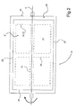
- the air distribution flap 15 is equipped with a peripheral sealing gasket 19, to guarantee a prohibition of passage of air through the channel 13, the inlet 4 or the outlet 8 of air which it team.
- the air distribution flap 15 consists of a core 20 made from the first material and a coating 21 made from the second material.
- the core 20 is arranged in a frame 22 inside which are formed openings 23.
- the frame 22 is provided with reinforcing ribs 24 which extend between two opposite edges 25,26 of the frame 22.
- the openings 23 are closed by the coating 21 to ensure an airtightness of the air distribution flap 15.
- the air distribution flap 15 is rotatable around an axis of rotation A which is confused with a reinforcing rib 24 to ensure robustness to the air distribution flap 15.
- the coating 21 and the core 20 are jointly obtained by bi-injection of the respective materials constituting them, or are made by overmolding the coating 21 on the core 20.
- This provides a material compatibility cohesion between the material of the first element and the material of the second element.
- the peripheral sealing lip 19 is easily made of the same material constituting the coating 21, extending at the periphery of the core 20 of the air distribution flap 15.
- the peripheral sealing lip 19 constitutes an overflow and / or extension of the coating 21 at the periphery of the core 20 and is performed during the same overmolding or bi-injection step during which the coating 21 is produced.
Landscapes
- Engineering & Computer Science (AREA)
- Physics & Mathematics (AREA)
- Thermal Sciences (AREA)
- Mechanical Engineering (AREA)
- Chemical & Material Sciences (AREA)
- Combustion & Propulsion (AREA)
- Air-Conditioning For Vehicles (AREA)
- Soundproofing, Sound Blocking, And Sound Damping (AREA)
Applications Claiming Priority (1)
| Application Number | Priority Date | Filing Date | Title |
|---|---|---|---|
| FR0704101A FR2917011A1 (fr) | 2007-06-08 | 2007-06-08 | Installation de ventilation, chauffage et/ou de climatisation d'un vehicule automobile agencee pour absorber les ondes acoustiques |
Publications (1)
| Publication Number | Publication Date |
|---|---|
| EP2000339A1 true EP2000339A1 (de) | 2008-12-10 |
Family
ID=38787576
Family Applications (1)
| Application Number | Title | Priority Date | Filing Date |
|---|---|---|---|
| EP08157364A Withdrawn EP2000339A1 (de) | 2007-06-08 | 2008-05-30 | Akustische Schallwellen absorbierende Kraftfahrzeugklimaanlage |
Country Status (3)
| Country | Link |
|---|---|
| EP (1) | EP2000339A1 (de) |
| KR (1) | KR20080108042A (de) |
| FR (1) | FR2917011A1 (de) |
Cited By (2)
| Publication number | Priority date | Publication date | Assignee | Title |
|---|---|---|---|---|
| WO2013175000A1 (de) * | 2012-05-24 | 2013-11-28 | Kreuzinger + Manhart Turbulenz Gmbh | Strömungskanalanordnung |
| DE102023120397A1 (de) * | 2023-08-01 | 2025-02-06 | Bayerische Motoren Werke Aktiengesellschaft | Schallgedämmte Belüftungsvorrichtung für ein Kraftfahrzeug sowie hiermit ausgestattetes Kraftfahrzeug |
Citations (3)
| Publication number | Priority date | Publication date | Assignee | Title |
|---|---|---|---|---|
| DE10261081B3 (de) * | 2002-12-20 | 2004-02-19 | Carcoustics Tech Center Gmbh | Luftführungselement, insbesondere Luftführungskanal für ein Kraftfahrzeug |
| DE102005027566A1 (de) * | 2004-06-18 | 2006-01-19 | Behr Gmbh & Co. Kg | Bauteil, insbesondere für eine Heizungs- und/oder Klimatisierungseinrichtung eines Kraftfahrzeugs |
| FR2876434A1 (fr) * | 2004-10-11 | 2006-04-14 | Technofan Sa | Dispositif d'obturation d'une conduite et ensemble de ventilation incluant un tel dispositif |
-
2007
- 2007-06-08 FR FR0704101A patent/FR2917011A1/fr not_active Withdrawn
-
2008
- 2008-05-30 EP EP08157364A patent/EP2000339A1/de not_active Withdrawn
- 2008-06-05 KR KR1020080053177A patent/KR20080108042A/ko not_active Ceased
Patent Citations (4)
| Publication number | Priority date | Publication date | Assignee | Title |
|---|---|---|---|---|
| DE10261081B3 (de) * | 2002-12-20 | 2004-02-19 | Carcoustics Tech Center Gmbh | Luftführungselement, insbesondere Luftführungskanal für ein Kraftfahrzeug |
| EP1470011A1 (de) | 2002-12-20 | 2004-10-27 | Carcoustics Tech Center GmbH | Luftführungselement, insbesondere luftführungskanal für ein kraftfahrzeug |
| DE102005027566A1 (de) * | 2004-06-18 | 2006-01-19 | Behr Gmbh & Co. Kg | Bauteil, insbesondere für eine Heizungs- und/oder Klimatisierungseinrichtung eines Kraftfahrzeugs |
| FR2876434A1 (fr) * | 2004-10-11 | 2006-04-14 | Technofan Sa | Dispositif d'obturation d'une conduite et ensemble de ventilation incluant un tel dispositif |
Cited By (3)
| Publication number | Priority date | Publication date | Assignee | Title |
|---|---|---|---|---|
| WO2013175000A1 (de) * | 2012-05-24 | 2013-11-28 | Kreuzinger + Manhart Turbulenz Gmbh | Strömungskanalanordnung |
| DE102023120397A1 (de) * | 2023-08-01 | 2025-02-06 | Bayerische Motoren Werke Aktiengesellschaft | Schallgedämmte Belüftungsvorrichtung für ein Kraftfahrzeug sowie hiermit ausgestattetes Kraftfahrzeug |
| DE102023120397B4 (de) * | 2023-08-01 | 2025-05-28 | Bayerische Motoren Werke Aktiengesellschaft | Schallgedämmte Belüftungsvorrichtung für ein Kraftfahrzeug sowie hiermit ausgestattetes Kraftfahrzeug |
Also Published As
| Publication number | Publication date |
|---|---|
| FR2917011A1 (fr) | 2008-12-12 |
| KR20080108042A (ko) | 2008-12-11 |
Similar Documents
| Publication | Publication Date | Title |
|---|---|---|
| EP0686520B2 (de) | Doppelwandige Türinnenverkleidung für Kraftfahrzeuge | |
| EP1288030B1 (de) | Luftstrommischanlage insbesondere für Kraftfahrzeug- Heizungs- und/oder Klimaanlagen | |
| EP1764245B1 (de) | Heizungs-, Lüftungs- und/oder Klimaanlage mit verbesserten akustischen Eigenschaften | |
| EP2889168B1 (de) | Vorrichtung zum Heizen, Belüften und/oder Klimatisieren | |
| EP2125401B1 (de) | Schalldämpfungssystem für kondensatabführung in der klimaanlage eines kraftfahrzeugs | |
| FR3079454A1 (fr) | Dispositif de regulation d'un flux d'air pour une entree d'air d'un vehicule automobile | |
| EP2894414A1 (de) | Lüftereinheit mit Geräuschdämpfer | |
| EP2000339A1 (de) | Akustische Schallwellen absorbierende Kraftfahrzeugklimaanlage | |
| FR3072912A1 (fr) | Element de siege avec un systeme de ventilation | |
| EP3847045B1 (de) | Kraftfahrzeug mit einer heizungs-, lüftungs- und/oder klimaanlage | |
| FR2920044A1 (fr) | Boitier constitutif d'une installation de ventilation, de chauffage et/ou de climatisation pourvu de moyens d'attenuation acoustique d'ondes sonores et installation comprenant un tel boitier | |
| FR2876172A1 (fr) | Dispositif d'attenuation acoustique d'un conduit de ventilation d'un vehicule automobile et procede de realisation d'un tel dispositif | |
| EP3619068A1 (de) | Poröser lufteinlasskanal für ein hlk-system | |
| FR2929558A1 (fr) | Organe de mixage d'air du type volet-tambour et installation de chauffage, de ventilation et/ou de climatisation equipee d'un tel organe de mixage d'air. | |
| FR3097943A1 (fr) | Dispositif de régulation d’un flux d’air pour une entrée d’air de véhicule automobile | |
| EP3749535A1 (de) | Lufttechnisches und akustisches behandlungssystem für ein luftmanagementsystem für ein fahrzeug | |
| WO2021084179A1 (fr) | Paroi poreuse et boitier d'installation de chauffage et/ou ventilation et/ou climatisation correspondant | |
| EP3481655A1 (de) | Heizungs-, lüftungs- und/oder klimatisierungsvorrichtung für ein kraftfahrzeug | |
| FR2891199A1 (fr) | Module multifonctionnel de collecte d'air et d'absorption d'energie, destine a etre monte entre un capot sur moteur et un pare-brise | |
| FR2893394A1 (fr) | Organe directionnel d'ejection d'air | |
| WO2024017910A1 (fr) | Installation de ventilation pour un véhicule | |
| FR2847855A1 (fr) | Dispositif de traitement d'air compact pour vehicule automobile | |
| FR2845946A1 (fr) | Appareil de chauffage, ventilation et/ou climatisation de l'habitacle d'un vehicule automobile comportant un volet de reglage d'air | |
| EP0897508B1 (de) | Luftzufuhrleitung, insbesondere für kraftfahrzeuge, und montageverfahren dafür | |
| EP3744606B1 (de) | Belüftungsvorrichtung für fahrzeug, die mindestens ein schallabsorptionselement umfasst, und entsprechendes fahrzeug |
Legal Events
| Date | Code | Title | Description |
|---|---|---|---|
| PUAI | Public reference made under article 153(3) epc to a published international application that has entered the european phase |
Free format text: ORIGINAL CODE: 0009012 |
|
| AK | Designated contracting states |
Kind code of ref document: A1 Designated state(s): AT BE BG CH CY CZ DE DK EE ES FI FR GB GR HR HU IE IS IT LI LT LU LV MC MT NL NO PL PT RO SE SI SK TR |
|
| AX | Request for extension of the european patent |
Extension state: AL BA MK RS |
|
| RIN1 | Information on inventor provided before grant (corrected) |
Inventor name: TRUILLET, FRANCK Inventor name: CHERIAUX, OLIVIER Inventor name: PAITRAULT, THIBAUT Inventor name: DROULEZ, ERIC Inventor name: LEBORGNE, JOSE |
|
| 17P | Request for examination filed |
Effective date: 20090601 |
|
| 17Q | First examination report despatched |
Effective date: 20090701 |
|
| AKX | Designation fees paid |
Designated state(s): AT BE BG CH CY CZ DE DK EE ES FI FR GB GR HR HU IE IS IT LI LT LU LV MC MT NL NO PL PT RO SE SI SK TR |
|
| STAA | Information on the status of an ep patent application or granted ep patent |
Free format text: STATUS: THE APPLICATION IS DEEMED TO BE WITHDRAWN |
|
| 18D | Application deemed to be withdrawn |
Effective date: 20100112 |