EP2000251A1 - Verfahren zum Reparaturschweißen von Wasserwandröhren - Google Patents
Verfahren zum Reparaturschweißen von Wasserwandröhren Download PDFInfo
- Publication number
- EP2000251A1 EP2000251A1 EP07301085A EP07301085A EP2000251A1 EP 2000251 A1 EP2000251 A1 EP 2000251A1 EP 07301085 A EP07301085 A EP 07301085A EP 07301085 A EP07301085 A EP 07301085A EP 2000251 A1 EP2000251 A1 EP 2000251A1
- Authority
- EP
- European Patent Office
- Prior art keywords
- water
- sleeve
- wall tubing
- wall
- tubing
- Prior art date
- Legal status (The legal status is an assumption and is not a legal conclusion. Google has not performed a legal analysis and makes no representation as to the accuracy of the status listed.)
- Withdrawn
Links
Images



Classifications
-
- B—PERFORMING OPERATIONS; TRANSPORTING
- B23—MACHINE TOOLS; METAL-WORKING NOT OTHERWISE PROVIDED FOR
- B23K—SOLDERING OR UNSOLDERING; WELDING; CLADDING OR PLATING BY SOLDERING OR WELDING; CUTTING BY APPLYING HEAT LOCALLY, e.g. FLAME CUTTING; WORKING BY LASER BEAM
- B23K33/00—Specially-profiled edge portions of workpieces for making soldering or welding connections; Filling the seams formed thereby
- B23K33/004—Filling of continuous seams
- B23K33/006—Filling of continuous seams for cylindrical workpieces
-
- B—PERFORMING OPERATIONS; TRANSPORTING
- B23—MACHINE TOOLS; METAL-WORKING NOT OTHERWISE PROVIDED FOR
- B23P—METAL-WORKING NOT OTHERWISE PROVIDED FOR; COMBINED OPERATIONS; UNIVERSAL MACHINE TOOLS
- B23P6/00—Restoring or reconditioning objects
-
- F—MECHANICAL ENGINEERING; LIGHTING; HEATING; WEAPONS; BLASTING
- F16—ENGINEERING ELEMENTS AND UNITS; GENERAL MEASURES FOR PRODUCING AND MAINTAINING EFFECTIVE FUNCTIONING OF MACHINES OR INSTALLATIONS; THERMAL INSULATION IN GENERAL
- F16L—PIPES; JOINTS OR FITTINGS FOR PIPES; SUPPORTS FOR PIPES, CABLES OR PROTECTIVE TUBING; MEANS FOR THERMAL INSULATION IN GENERAL
- F16L55/00—Devices or appurtenances for use in, or in connection with, pipes or pipe systems
- F16L55/16—Devices for covering leaks in pipes or hoses, e.g. hose-menders
- F16L55/162—Devices for covering leaks in pipes or hoses, e.g. hose-menders from inside the pipe
- F16L55/165—Devices for covering leaks in pipes or hoses, e.g. hose-menders from inside the pipe a pipe or flexible liner being inserted in the damaged section
- F16L55/1657—Devices for covering leaks in pipes or hoses, e.g. hose-menders from inside the pipe a pipe or flexible liner being inserted in the damaged section lengths of rigid pipe being inserted
-
- F—MECHANICAL ENGINEERING; LIGHTING; HEATING; WEAPONS; BLASTING
- F22—STEAM GENERATION
- F22B—METHODS OF STEAM GENERATION; STEAM BOILERS
- F22B37/00—Component parts or details of steam boilers
- F22B37/02—Component parts or details of steam boilers applicable to more than one kind or type of steam boiler
- F22B37/10—Water tubes; Accessories therefor
-
- F—MECHANICAL ENGINEERING; LIGHTING; HEATING; WEAPONS; BLASTING
- F28—HEAT EXCHANGE IN GENERAL
- F28F—DETAILS OF HEAT-EXCHANGE AND HEAT-TRANSFER APPARATUS, OF GENERAL APPLICATION
- F28F11/00—Arrangements for sealing leaky tubes and conduits
-
- F—MECHANICAL ENGINEERING; LIGHTING; HEATING; WEAPONS; BLASTING
- F28—HEAT EXCHANGE IN GENERAL
- F28D—HEAT-EXCHANGE APPARATUS, NOT PROVIDED FOR IN ANOTHER SUBCLASS, IN WHICH THE HEAT-EXCHANGE MEDIA DO NOT COME INTO DIRECT CONTACT
- F28D7/00—Heat-exchange apparatus having stationary tubular conduit assemblies for both heat-exchange media, the media being in contact with different sides of a conduit wall
- F28D7/0041—Heat-exchange apparatus having stationary tubular conduit assemblies for both heat-exchange media, the media being in contact with different sides of a conduit wall the conduits for only one medium being tubes having parts touching each other or tubes assembled in panel form
Definitions
- the invention disclosed herein relates to combustion systems and, in particular, to repair ofwaterwall tubing.
- Combustion systems make use of a variety of devices for generation of steam and moving that steam.
- One such combustion system is a boiler.
- the waterwall typically lines the walls of the furnace and includes a plurality of tubes that are welded together.
- the tubes carry water (i.e., coolant) into the furnace where combustion takes place.
- the heat of combustion is transferred to the waterwall and steam is generated within the tubes.
- the tubes are subject to degradation. Accordingly, system operators conduct periodic inspections of the tubes to ensure efficient operation.
- FIG. 1 there are shown aspects of an embodiment of a Steam Generation System (SGS) 10.
- the SGS 10 includes a combustor 2 (also referred to as a "boiler” and by other similar terms) as well as various other components.
- combustor 2 also referred to as a "boiler” and by other similar terms
- FIG. 1 there are shown aspects of an embodiment of a Steam Generation System (SGS) 10.
- the SGS 10 includes a combustor 2 (also referred to as a "boiler” and by other similar terms) as well as various other components.
- combustor 2 also referred to as a "boiler” and by other similar terms
- this illustration and description present only a section of a simplified combustion system, and that this example is not limiting of combustion systems.
- crushed fuel e.g., coal
- sorbent e.g., limestone
- Primary air is supplied to a bottom portion of the combustor 2 through an air distributor, with secondary air fed through one or more elevations of air ports in a lower portion of the combustor 2.
- the combustor 2 generally includes two regions. A lower portion and an upper portion.
- the lower portion of the combustor 2 includes the fuel, a primary air distributor, secondary air ports, fuel feed ports and solids recycle ports.
- the density of the bed in this region it relatively high on average and typically highest at the elevation of the air distributor. The density then drops off with increasing height of the combustor 2.
- the lower portion is usually rectangular, tapered and formed from finned or fusion welded water-wall tubing 15.
- the lower portion is typically lined with refractory to protect the water-wall tubing 15.
- the water-wall tubing 15 is supplied boilerwater (e.g., water, water with certain chemicals, etc,...) by an inlet header 17.
- the inlet header 17 provides the boilerwater for steam generation in the water-wall tubing 15 of the combustor 2.
- the upper portion of the combustor 2 is usually rectangular with vertical walls, where the walls are formed with finned or fusion welded water-wall tubing 15.
- the upper portion is typically unlined to maximize heat transfer to the water-wall tubing 15.
- the walls of the combustor 2 are cooled by circulation in the water-wall tubing 15.
- the prior art SGS 10 includes a boiler drum 8 which receives steam and moisture from the water-wall tubing 15 (through various components, such as a collection header).
- the boiler drum 8 provides for separation of water (W) and steam (S).
- the surface area of the water-wall tubing 15 is up to about 7,000 square meters (m 2 ).
- Sleeve substitution on water-wall tubing 15 is a long and delicate operation. This process calls for a cooling down period of a few days, and access to each side of the tubing (internal and external of the furnace, for instance), all of which require access to the water-wall tubing 15 with the placement of a scaffold.
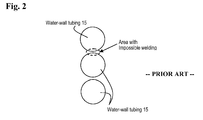
- FIG. 2 depicts an area where welding of water-wall tubing 15 has been impossible without disturbing other tubing.
- Open Window When only one side is accessible, the first attempt is a method referred to as "Open Window.” This method falls short because it transforms a weldless tubular element (i.e., the water-wall tubing 15) into an element with a longitudinal weld.
- the longitudinal weld is not compatible with the requirements of construction codes and rules.
- the techniques provide for reduced labor and time savings.
- a method for performing repair to a length of water-wall tubing including: aligning a substitution sleeve in the length; welding an upper internal portion and a lower internal portion of the sleeve to the water-wall tubing; placing an upper and a lower element into a respective cutback of the sleeve; and welding an upper external portion and a lower external portion of the sleeve to the respective elements and the water-wall tubing to repair the sleeve.
- an apparatus for repairing a length L of water-wall tubing including: a substitution sleeve of the length L including a cutback portion at each end and a cutting element for each cutback, wherein each of the sleeve and the elements are adapted for welding to the water-wall tubing.
- FIG. 1 depicts aspects of a prior art combustor having water-wall tubing
- FIG. 2 depicts an area within water-wall tubing where welding has not been possible
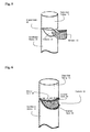
- FIG. 3 depicts aspects of a damaged tube of the water-wall tubing
- FIG. 4 depicts a substitution sleeve
- FIG. 5 depicts the substitution sleeve in place within a water-wall tube
- FIG. 6 depicts aspects of the substitution sleeve installed into a tube of the water-wall.
- FIG. 7 depicts an exemplary method for repairing water-wall tubing.
- SGS Steam Generation System
- the term "repair" makes reference to performance of a repair task with a resulting installation that meets code, rule and other performance requirements.
- the teachings herein provide for replacing a portion of water-wall tubing 15 by accessing only one side of the water-wall tubing 15.
- the repair preserves mechanical characteristics of the tubing. Further, the repair techniques disclosed save time and money as cooling time of the boiler is reduced, thus reducing downtime.
- the water-wall tubing 15 includes a plurality of tubes for carrying water (i.e., coolant, which may include water and other chemicals, such as corrosion and erosion inhibitors).
- water i.e., coolant, which may include water and other chemicals, such as corrosion and erosion inhibitors.
- the water-wall tubing 15 is disposed along interior portions of a combustion chamber.
- the water-wall tubing 15 is generally characterized as having a back of the water wall 17 and a front of the water wall 16. When installed, the back of the water wall 17 is inaccessible. That is, some intermediate step, such as cutting through the water-wall tubing 15 must be performed to access the back of the water wall 17. The back of the water wall 17 is generally exposed to the combustion chamber. Typically, the back portion of the water wall tubing 15 is subject to failure due to the harsh environment. As shown in FIG. 3 , a portion of a damaged tube 20 has been removed from the water-wall tubing 15. In this example, the portion of the damaged tube 20 includes a perforation. Repair of the perforation first calls for removing the portion of damaged tube 20 by conventional techniques such as with a cutting torch, a grinder and other such devices. Next, a replacement is inserted. An exemplary replacement is shown in FIG. 4 .
- the substitution sleeve 30 is typically formed of material that is similar to material of the water-wall tubing 15 and is of a similar thickness. Of course, variations and improvements to materials and dimensions may be used as determined appropriate.
- the substitution sleeve 30 is typically of the same length as the portion of damaged tube 20, such that the substitution sleeve 30 may be welded in place of the portion of damaged tube 20.
- the term "similar” as used in this regard is related to material or dimensions that of a similar appearance, availability, cost, durability, longevity, or other such aspects of the water-wall tubing 15.
- the substitution sleeve 30 includes an upper and a lower cutback 31.
- the cutback 31 provides an access way for subsequent internal welding.
- An element 32 is generally provided with the substitution sleeve 30 for each of the upper and the lower cutback 31.
- Each element 32 serves as filler material for subsequent external welding.
- the element 32 may be adapted as necessary. That is, for each element 32, aspects such as a shape, size, material, mounting features (e.g., weld points) and other such aspects may be adapted as necessary. In each embodiment, the element 32 includes a design that never requires longitudinal welding for installation.
- the substitution sleeve 30 is disposed in line with the damaged water-wall tubing 15. Once aligned, an internal weld 40 is formed by a welding procedure.
- the cutback 31 provides room and accessibility for tooling for the welding procedure. Once the internal weld 40 is in place, the upper and lower elements 32 are set and an external weld 50 is performed.
- the element 32 is installed into the water-wall tubing 15.
- Each element 32 provides an adequate supply of material necessary for filling the cutback 31 once welded into place.
- the element 32 is surrounded by an external weld 50. Once the internal weld 40 and the external weld 50 are in place (for the upper and lower portion of the substitution sleeve 30), the water-wall tubing 15 may be subjected to inspection or considered repaired.
- the apparatus typically includes the substitution sleeve 30 and two elements 32.
- separate elements 32 are provided. That is, elements 32 which are not cut from the length L.
- separate elements include additional material or other features as may be useful to welders placing each element 32.
- the apparatus is useful for repair of water-wall technology implemented in most any embodiment of a combustor 2, combustion chamber, heat exchanger or other similar device.
- repair personnel make the substitution sleeve 30, the cutback 31 and the element 32 in the field from blank stock. That is, a section of material is available to the personnel. Once an extent of the damaged portion of tubing 20 is determined, the personnel cut appropriately sized materials. Accordingly, FIG. 7 depicts an exemplary method for performing a repair.
- an exemplary repair method 60 is provided.
- repair personnel identify and remove a length L of damaged tubing.
- the personnel cut a substitution sleeve 30 of length L.
- upper and lower elements 32 are removed from the substitution sleeve 30.
- the substitution sleeve is aligned in a blank section of the water-wall tubing 15 (that is, a section where the damaged portion has been removed).
- personnel perform internal welding to provide the interior weld 40 which couples the substitution sleeve 30 to the back of the water-wall tubing 15.
- a sixth step 66 the upper and lower elements 32 are placed and external welding is performed to provide the external weld 50. Once the external weld 50 is completed, the water-wall is repaired (or sealed). Of course, some of these steps may be omitted, performed out of order, added to, or otherwise modified for performing a repair.
- the teachings herein provide for performing welding on a damaged water-wall tube without the required rearrangement of tubes in a water wall as previously required.
- the description herein makes reference to specific types of boilers, the teachings may be used on all types of boilers, and further, these may be used to weld any tubular product.
Landscapes
- Engineering & Computer Science (AREA)
- Mechanical Engineering (AREA)
- General Engineering & Computer Science (AREA)
- Physics & Mathematics (AREA)
- Thermal Sciences (AREA)
- Heat-Exchange Devices With Radiators And Conduit Assemblies (AREA)
- Butt Welding And Welding Of Specific Article (AREA)
Priority Applications (3)
| Application Number | Priority Date | Filing Date | Title |
|---|---|---|---|
| EP07301085A EP2000251A1 (de) | 2007-06-05 | 2007-06-05 | Verfahren zum Reparaturschweißen von Wasserwandröhren |
| CA2687885A CA2687885C (en) | 2007-06-05 | 2008-05-20 | Repair welding method for waterwall tubes |
| PCT/EP2008/056159 WO2008148636A1 (en) | 2007-06-05 | 2008-05-20 | Repair welding method for waterwall tubes |
Applications Claiming Priority (1)
| Application Number | Priority Date | Filing Date | Title |
|---|---|---|---|
| EP07301085A EP2000251A1 (de) | 2007-06-05 | 2007-06-05 | Verfahren zum Reparaturschweißen von Wasserwandröhren |
Publications (1)
| Publication Number | Publication Date |
|---|---|
| EP2000251A1 true EP2000251A1 (de) | 2008-12-10 |
Family
ID=38654637
Family Applications (1)
| Application Number | Title | Priority Date | Filing Date |
|---|---|---|---|
| EP07301085A Withdrawn EP2000251A1 (de) | 2007-06-05 | 2007-06-05 | Verfahren zum Reparaturschweißen von Wasserwandröhren |
Country Status (3)
| Country | Link |
|---|---|
| EP (1) | EP2000251A1 (de) |
| CA (1) | CA2687885C (de) |
| WO (1) | WO2008148636A1 (de) |
Cited By (4)
| Publication number | Priority date | Publication date | Assignee | Title |
|---|---|---|---|---|
| CN107234401A (zh) * | 2017-07-30 | 2017-10-10 | 湖北宜昌东山电力有限责任公司 | 墙角引水钢管断裂修复方法 |
| JP2019095133A (ja) * | 2017-11-24 | 2019-06-20 | 三菱日立パワーシステムズ株式会社 | 火炉壁の補修方法 |
| JP2020131212A (ja) * | 2019-02-14 | 2020-08-31 | 株式会社Ihi | 配管溶接方法及び配管溶接装置 |
| CN112719780A (zh) * | 2021-01-25 | 2021-04-30 | 俊炜建材(深圳)有限公司 | 一种大棚钢管维护设备 |
Families Citing this family (6)
| Publication number | Priority date | Publication date | Assignee | Title |
|---|---|---|---|---|
| US8196969B2 (en) * | 2008-12-09 | 2012-06-12 | Johnston Iii John Graham | Pre-machined window weld for breached tubing |
| CN101797677B (zh) * | 2010-01-07 | 2011-09-07 | 孙健峰 | 应用激光和微弧火花复合技术修复直臂金属薄壁管的方法 |
| CN102062389B (zh) * | 2011-01-21 | 2013-01-30 | 马敏 | 一种锅炉水冷壁管活接头 |
| JP7164310B2 (ja) * | 2018-03-12 | 2022-11-01 | 三菱重工業株式会社 | 火炉壁管を交換する方法 |
| CN112222755A (zh) * | 2020-10-20 | 2021-01-15 | 华瑞(江苏)燃机服务有限公司 | 一种燃机二级燃料喷嘴部件喷嘴的修复工艺 |
| CN116877980A (zh) * | 2023-07-18 | 2023-10-13 | 上海锅炉厂有限公司 | 一种墙式再热器加装方法 |
Citations (3)
| Publication number | Priority date | Publication date | Assignee | Title |
|---|---|---|---|---|
| US4047659A (en) * | 1976-01-02 | 1977-09-13 | United States Steel Corporation | Method for replacing worn tubes in a gas hood |
| JPH08281468A (ja) * | 1995-04-10 | 1996-10-29 | Mitsubishi Heavy Ind Ltd | 管補修溶接方法及び装置 |
| US20030094440A1 (en) * | 2001-11-16 | 2003-05-22 | Gandy David Wayne | Method and apparatus and prefabricated replacement tube for localized waterwall repair |
-
2007
- 2007-06-05 EP EP07301085A patent/EP2000251A1/de not_active Withdrawn
-
2008
- 2008-05-20 WO PCT/EP2008/056159 patent/WO2008148636A1/en not_active Ceased
- 2008-05-20 CA CA2687885A patent/CA2687885C/en not_active Expired - Fee Related
Patent Citations (3)
| Publication number | Priority date | Publication date | Assignee | Title |
|---|---|---|---|---|
| US4047659A (en) * | 1976-01-02 | 1977-09-13 | United States Steel Corporation | Method for replacing worn tubes in a gas hood |
| JPH08281468A (ja) * | 1995-04-10 | 1996-10-29 | Mitsubishi Heavy Ind Ltd | 管補修溶接方法及び装置 |
| US20030094440A1 (en) * | 2001-11-16 | 2003-05-22 | Gandy David Wayne | Method and apparatus and prefabricated replacement tube for localized waterwall repair |
Cited By (4)
| Publication number | Priority date | Publication date | Assignee | Title |
|---|---|---|---|---|
| CN107234401A (zh) * | 2017-07-30 | 2017-10-10 | 湖北宜昌东山电力有限责任公司 | 墙角引水钢管断裂修复方法 |
| JP2019095133A (ja) * | 2017-11-24 | 2019-06-20 | 三菱日立パワーシステムズ株式会社 | 火炉壁の補修方法 |
| JP2020131212A (ja) * | 2019-02-14 | 2020-08-31 | 株式会社Ihi | 配管溶接方法及び配管溶接装置 |
| CN112719780A (zh) * | 2021-01-25 | 2021-04-30 | 俊炜建材(深圳)有限公司 | 一种大棚钢管维护设备 |
Also Published As
| Publication number | Publication date |
|---|---|
| CA2687885C (en) | 2013-04-02 |
| CA2687885A1 (en) | 2008-12-11 |
| WO2008148636A1 (en) | 2008-12-11 |
Similar Documents
| Publication | Publication Date | Title |
|---|---|---|
| CA2687885C (en) | Repair welding method for waterwall tubes | |
| Annaratone | Steam generators: description and design | |
| KR101981148B1 (ko) | 증기 발생기 가열관 수리 수단 및 수리 방법 | |
| RU2554679C2 (ru) | Подогреватель воздуха топочным газом, способ установки, а также воздушный трубный компонент для подогревателя воздуха топочным газом | |
| EP0148453A2 (de) | Flexibler Stabilisator für schadhafte Wärmetauscherrohre | |
| KR101928374B1 (ko) | 배열회수보일러 | |
| CN101330991A (zh) | 通过吹入介质清洁发电站构件的方法和设备以及测量介质纯度的测量装置 | |
| JP2017089909A (ja) | 節炭器及びボイラ並びに伝熱管の補修方法 | |
| US5781995A (en) | Method of repairing a defective portion in a fluid carrying tube | |
| WO2020027095A1 (ja) | 運転支援方法及び運転支援システム | |
| US7487745B2 (en) | Boiler tube position retainer assembly | |
| Pearson et al. | Reliability and durability from large heat recovery steam generators | |
| Dooley et al. | Trends in hrsg reliability–a 10-year review | |
| Brodov et al. | State of the art and trends in the design and operation of high-and low-pressure heaters for steam turbines at thermal and nuclear power plants in Russia and abroad: Part 2. Heater design and operation peculiarities | |
| JP6632438B2 (ja) | 排熱回収ボイラの補修方法 | |
| EP3739264A1 (de) | Abfall-verbrennungsanlage für feststoff und verfahren zum austausch seines düseneinsatzes | |
| Yokell | Maintaining and Repairing Heat Exchanger Tubes | |
| US6047649A (en) | Method and arrangement in cooling medium circulation of a recovery boiler | |
| JP5249535B2 (ja) | 熱交換器およびその補修方法 | |
| JP6307032B2 (ja) | 損傷した伝熱管の応急処置具及び伝熱管の応急処置方法 | |
| Nightingale | Thermal and Mechanical Design Guidelines and General Considerations for the Proper Design, and Location, of Various Types of Service Connections on Steam Surface Condensers | |
| JP5106445B2 (ja) | 修復用配管、修復済みボイラウインドボックス、及びボイラウインドボックスの修復方法 | |
| Hasan | Faults Diagnosis and Their Remedies in the Manufacturing of Heat Exchangers: A Case Study | |
| BHATTACHARYA | Investigation of repeated economiser tube failures of a 135 tph cold cyclone CFB boiler–a case study | |
| Pasha et al. | Design and Modification of Heat Recovery Steam Generators for Cycling Operations |
Legal Events
| Date | Code | Title | Description |
|---|---|---|---|
| PUAI | Public reference made under article 153(3) epc to a published international application that has entered the european phase |
Free format text: ORIGINAL CODE: 0009012 |
|
| AK | Designated contracting states |
Kind code of ref document: A1 Designated state(s): AT BE BG CH CY CZ DE DK EE ES FI FR GB GR HU IE IS IT LI LT LU LV MC MT NL PL PT RO SE SI SK TR |
|
| AX | Request for extension of the european patent |
Extension state: AL BA HR MK RS |
|
| 17P | Request for examination filed |
Effective date: 20090513 |
|
| AKX | Designation fees paid |
Designated state(s): AT BE BG CH CY CZ DE DK EE ES FI FR GB GR HU IE IS IT LI LT LU LV MC MT NL PL PT RO SE SI SK TR |
|
| 17Q | First examination report despatched |
Effective date: 20150529 |
|
| STAA | Information on the status of an ep patent application or granted ep patent |
Free format text: STATUS: THE APPLICATION IS DEEMED TO BE WITHDRAWN |
|
| 18D | Application deemed to be withdrawn |
Effective date: 20151009 |